EP0149996A2 - Method and machine for manufacturing brushes - Google Patents
Method and machine for manufacturing brushes Download PDFInfo
- Publication number
- EP0149996A2 EP0149996A2 EP85100059A EP85100059A EP0149996A2 EP 0149996 A2 EP0149996 A2 EP 0149996A2 EP 85100059 A EP85100059 A EP 85100059A EP 85100059 A EP85100059 A EP 85100059A EP 0149996 A2 EP0149996 A2 EP 0149996A2
- Authority
- EP
- European Patent Office
- Prior art keywords
- bristle bundles
- bristle
- brush body
- machine according
- bundles
- Prior art date
- Legal status (The legal status is an assumption and is not a legal conclusion. Google has not performed a legal analysis and makes no representation as to the accuracy of the status listed.)
- Withdrawn
Links
Images


Classifications
-
- A—HUMAN NECESSITIES
- A46—BRUSHWARE
- A46B—BRUSHES
- A46B3/00—Brushes characterised by the way in which the bristles are fixed or joined in or on the brush body or carrier
- A46B3/06—Brushes characterised by the way in which the bristles are fixed or joined in or on the brush body or carrier by welding together bristles made of metal wires or plastic materials
-
- A—HUMAN NECESSITIES
- A46—BRUSHWARE
- A46D—MANUFACTURE OF BRUSHES
- A46D3/00—Preparing, i.e. Manufacturing brush bodies
-
- A—HUMAN NECESSITIES
- A46—BRUSHWARE
- A46D—MANUFACTURE OF BRUSHES
- A46D3/00—Preparing, i.e. Manufacturing brush bodies
- A46D3/04—Machines for inserting or fixing bristles in bodies
- A46D3/045—Machines for inserting or fixing bristles in bodies for fixing bristles by fusing or gluing to a body
-
- B—PERFORMING OPERATIONS; TRANSPORTING
- B29—WORKING OF PLASTICS; WORKING OF SUBSTANCES IN A PLASTIC STATE IN GENERAL
- B29C—SHAPING OR JOINING OF PLASTICS; SHAPING OF MATERIAL IN A PLASTIC STATE, NOT OTHERWISE PROVIDED FOR; AFTER-TREATMENT OF THE SHAPED PRODUCTS, e.g. REPAIRING
- B29C45/00—Injection moulding, i.e. forcing the required volume of moulding material through a nozzle into a closed mould; Apparatus therefor
- B29C45/14—Injection moulding, i.e. forcing the required volume of moulding material through a nozzle into a closed mould; Apparatus therefor incorporating preformed parts or layers, e.g. injection moulding around inserts or for coating articles
- B29C45/14336—Coating a portion of the article, e.g. the edge of the article
- B29C45/14385—Coating a portion of a bundle of inserts, e.g. making brushes
-
- Y—GENERAL TAGGING OF NEW TECHNOLOGICAL DEVELOPMENTS; GENERAL TAGGING OF CROSS-SECTIONAL TECHNOLOGIES SPANNING OVER SEVERAL SECTIONS OF THE IPC; TECHNICAL SUBJECTS COVERED BY FORMER USPC CROSS-REFERENCE ART COLLECTIONS [XRACs] AND DIGESTS
- Y10—TECHNICAL SUBJECTS COVERED BY FORMER USPC
- Y10S—TECHNICAL SUBJECTS COVERED BY FORMER USPC CROSS-REFERENCE ART COLLECTIONS [XRACs] AND DIGESTS
- Y10S425/00—Plastic article or earthenware shaping or treating: apparatus
- Y10S425/805—Comb or brush
Definitions
- the invention relates to a method for producing brushes, in which many bundles of bristles, preferably all bundles of bristles of the brush, are first transported through guide channels into a specific position relative to a brush body and subsequently connected to the brush body at one of their ends (connecting ends) .
- brushes are to be understood to mean all objects which have a body which is covered with bristles, the size not being important.
- brushes include both very small brushes, e.g. Toothbrushes as well as large brooms, e.g. Street broom, understood.
- bristles are bteilers removed by means of an A from a magazine, folded in a filling tool and means of wire in front of drilled holes attached by relatively thick-walled brush bodies.
- machines are used (DE-PS 114 462) with which brush bodies can be rotated in different positions in order to drill holes in any direction and to be able to insert them into these bundles of bristles by means of wire.
- the free bristle ends are then sheared off and cleaned.
- machines of this type are manufactured as twin machines on which all four operations (drilling, tamping, shearing, cleaning) are carried out twice at the same time.
- the working speed of such machines is limited because the brush bodies have to be moved in three planes with a complicated movement sequence, whereby considerable inertial forces have to be overcome.
- the limit of the working speed is about 300 operations per minute and cannot be exceeded due to the required retrieval accuracy of the borehole.
- a machine (US Pat. No. 3,604,043) with which bristles made of thermoplastic are connected by welding to a brush body made of the same thermoplastic.
- the machine has a bristle magazine in which bristles cut to length are stacked. Holes are inserted through the holes in the magazine wall, which sit on a holder and are filled with bristles when inserted into the magazine. The free ends of the bristles are then melted using a heating element.
- the brush body is also melted at the attachment points of the bristle bundles by means of a heating element and then welded to several bristle bundles at the same time.
- the brush bodies of brushes produced in this way can be made relatively thin-walled and thus save material.
- the invention relates to a fertilizer grain.
- the object of the present invention is to provide a fertilizer grain which improves the soil cure without dosing problems when using the fertilizer, that is to say the soil is to be rebuilt when it is used up, and the latter is ultimately to be stabilized. in both the upper and lower soil layers.
- fertilizer grain according to the invention is introduced into the soil, it disintegrates and the fertilizer shows the effect described below.
- the rock powder prevents the nutrients from washing out of the soil, and at the same time regulates the acid balance of the soil, in particular acidic industrial rain is neutralized.
- the rock powder together with the fermentation humus prevents the soil from crusting the. It is disadvantageous, however, that brushes of any shape cannot be produced with the method, for example round-head brushes with bristles that extend over 180 ° or even over 360 °.
- a method of the type mentioned at the outset (DE-OS 28 49 510) is also known, in which bristle bundles are either removed from a magazine from cut bristles or brush bundles are separated from a strand and are brought to a brush body via short guide channels.
- the bristle bundles must remain so that the individual bristles cannot separate from each other, so that brushes can be produced with the bristles pointing in different directions, and all bristle bundles can be welded on simultaneously, so that a large production capacity is achieved.
- the method cannot be used to attach bristle bundles to the brush body in any direction, since because of the need to hold the bundles together, the guide channels can only be formed briefly and therefore only small changes in direction are possible.
- the invention has for its object to propose a method with which it is possible to produce brushes of any shape, e.g. also brushes with bristles all around.
- the invention is also intended to create machines with which the method can be carried out.
- each bundle of bristles is a coherent unit that can be passed through pipes of any length without the risk that the bundle of bristles will dissolve. There is thus a great deal of freedom in the laying of the pipelines, so that the bristle bundles can be brought up to the brush body in any direction. This makes it possible to produce brushes of any shape For example, brushes with bristles all around.
- the bundles of bristles can be connected to the brush body in various ways. If the bristles consist of thermoplastic material, they can be connected to a bundle of bristles by welding (claim 3). The bristles can also be extrusion-coated with plastic at their connecting ends. With this method, bristles can be connected to a brush body with which they themselves cannot be welded if the plastic with which the bristle bundles have been encapsulated can in turn be welded to the brush body.
- the bundles of bristles can be transported in the pipelines in various ways. Conveying using compressed air is particularly simple (claim 5). In this case, the bundles of bristles are transported in a pneumatic tube system similar to the containers. With this method, long distances can be covered and the construction of the necessary machine is low. However, the bundles of bristles can also be pushed mechanically through the guide channels (claim 6).
- the bristle bundles are guided with their connecting ends into a mold cavity and the brush body is produced in the mold cavity.
- thermoplastic material can be injected into the mold cavity (claim 12).
- plastic can also be foamed in the mold cavity (claim 13).
- This also forms a solid brush body, which, however, consists of porous material and is therefore light in weight.
- Such brush bodies are particularly suitable for large brushes, such as brooms.
- casting resin can be introduced into the mold cavity, which hardens by chemical reaction (claim 14).
- a hollow brush body can also be formed in the mold cavity (claim 15).
- the blow molding process (claim 16) and deep drawing (claim 17) are suitable for this.
- the mold cavity can be sealed according to claim 18 in that the connecting ends of the bristle bundle against the Mouths of the holes are pressed through which the bristle bundles protrude into the mold cavity.
- the bristle bundles can be fixed axially beforehand (claim 19).
- a connection between the bristle bundle and the brush body can be made according to claim 20 by inserting the connecting ends of the bristle bundles into holes in a prefabricated brush body and then creating a positive connection against pulling out.
- the positive connection can be carried out according to claim 21 by narrowing the inlet mouths of the holes. Ultrasound or friction can be used to plasticize the brush body material. It is also possible (claim 22) to insert the bristle bundles into undercut holes and to thicken the connection ends after insertion to produce a positive connection.
- the method specified in claim 22A is based on a method as described in DE-OS 28 49 510.
- Claims 23 to 29 describe a machine with which prefabricated brush bodies are equipped with bundles of bristles.
- Claims 30 to 38 relate to machines in which brush bodies are produced, the bristle bundles being anchored in the brush body with the production of the brush bodies. The method according to claims 11 to 19 can thus be carried out.
- Claims 39 to 43 relate to devices with which bristle bundles in the machine are applied to the various tubes lines are distributed.
- the claims 44 to 47 betref- fe n means to transport the bristle bundles within the pipelines, while the claims 49 to 55 relate to chores for the production of bristle bundles.
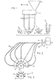
- a magazine 1 for bristle bundles has a magazine 1 for bristle bundles, a distributor block 2, pipes 3 extending from the distributor block 2, a bristle bundle holder 4, a heating device 5 for the plasticization of brush bodies in places and a magazine 6 for brush bodies.
- brushes are made as follows.
- Brush bodies 7 are removed from the magazine 6 for brush bodies and guided to the heating device 5.
- the heating device 5 has a plurality of heating elements 8, which are arranged in accordance with the intended attachment points for bristle bundles.
- the brush body 7 consisting of thermoplastic material is softened in places.
- the brush body is then transported to the bristle bundle holder 4. All bristle bundles are simultaneously transported to the bristle bundle holder via the pipelines 3 and are moved with their connecting ends against the brush body 7.
- the connections that of the bristle bundle is preferably plasticized, so that a good welding of the bristle bundle 9 to the previously heated points of the brush body 7 occurs.
- the bristle bundle holder is retracted, after which the brush can be removed.
- the brush manufacturing machine according to FIG. 2 works in the same way as the machine according to FIG. 1.
- the pipelines designated here with 3 ' likewise start from a distributor block 2' and lead to a bristle bundle holder 4 '.
- the bristle bundle holder 4 ' differs from the bristle bundle holder 4 according to FIG. 1 in that it extends over an angle of 180 °, while the bristle bundle holder 4 according to FIG. 1 extends over an angle of only 90 °.
- the pipelines 3 'must therefore bring about much greater changes in direction for the bristle bundles, but this is readily possible since the bristle bundles cannot dissolve due to the connection of the individual bristles to one another, even on long transport routes.
- the bristle bundle holder 4 therefore contains axially movable nozzles 10 which can be individually retracted, as a result of which the bristle bundles are released.
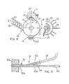
- a nozzle 10 is shown in detail in FIG. 6 and will be discussed below.
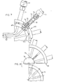
- the formation of a distributor block 2 with associated elements, which are also shown in FIG. 2, will also be discussed with reference to FIGS. 9 and 10.
- the pipes 3, 3 ' can be both rigid pipes and flexible hoses. Flexible hoses and rigid pipes can also be combined within one pipe.
- a drum 14 which can be rotated by 90 ° in the direction of arrow 15.
- Four stations are arranged on the circumference of the drum 14, namely a feed station 16 for brush bodies, a heating station 17 for the plasticization of brush bodies in places, an attachment station 18 in which plasticized bristle bundles are fastened to the heated brush body and an ejection station 19 in which finished brushes are ejected will.
- the feed station there is a magazine 20 for brush bodies 21 which slide in the inclined magazine shaft 22 towards the drum 24 due to the action of gravity. A brush body is clamped there. After the drum has been rotated through 90 °, the brush body 21 arrives in the heating station, in which there is a heating device 23, which in turn is equipped with individual heating elements 24 for locally heating the brush body, as already shown in FIG. 1 (heating device 5 with heating elements 8) has been described.
- the heated brush body 21 is brought into the fastening station by a further rotation step of the drum through 90 °.
- a bristle bundle holder 25 to which pipes 26 are brought are communicating with nozzles 27.
- the bristle bundles held in the nozzles 27 are plasticized at their connecting ends by means of a heating device 28.
- the heating element 28 is removed and the B orstenbündelhalter 25 is moved in the direction of arrow 29 by means of a not-shown moving device in the direction of the brush body 21st
- the processes are coordinated in time so that the heated points of the brush body are still plastic when the likewise plasticized ends of the bristle bundles come into contact with the brush body 21.
- the bristle bundle holder 25 is withdrawn or axially movable nozzles 27 are moved relative to the bristle bundle holder 25, whereby the bristles are released.
- the finished brush 30 reaches the ejection station and is ejected there.
- FIG. 5 shows an end region of a pipeline 31 for the conveyance of bristle bundles.
- An end piece 32 of the pipeline is rigid and is attached to a bristle bundle holder 33.
- the end piece 32 has a connecting piece 32a which is aligned with a front part of the end piece 32.
- the front part 32b merges towards the rear into a line part 32c which runs obliquely to the front section 32b.
- a rod 34 engages the socket 32a, which emanates from a pressure medium cylinder 35 with which the rod 34 can be pushed back and forth.
- a hose 36 or a rigid line part can be connected to the line part 32c.
- Pipelines 31 are used as follows. Bristle bundles are conveyed through the hose 36 and the line part 32c by compressed air into the line part 32b. When a bundle of bristles has reached line part 32b, it can be mechanically pushed forward by pushing rod 34 in order to press the bundle of bristles against a heating element and then against a brush body with a precisely defined force.
- the device according to FIG. 5 has the advantage that bundles of bristles can be conveyed by means of compressed air over an arbitrarily long way and nevertheless a defined pressure on a brush body is possible.
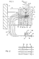
- a sleeve 39 In a base body 37 of the bristle bundle holder 4 '(see FIG. 2) there is a bore 38 in which a sleeve 39 can be slid.
- the sleeve 39 has in its upper region a collar 40 which acts as a piston and is movable in a short cylinder 41 which is incorporated in the base body 37.
- An air inlet bore 43 is provided inside the cover 42, which opens into a space 44 communicating with the cylinder 41.
- Below the cylinder 41 there is a space 45 which communicates with it and into which an air duct 46 opens.
- a further sleeve 47 is axially movable in the sleeve 39.
- a piston 48 is worked, which in egg Nem cylinder 49 is slidable.
- An air duct 50 opens into the cylinder 49.
- the cylinder 49 is closed at the top by a guide bush 51 in which the sleeve 47 is guided.
- the sleeve 39 is surrounded by a helical compression spring 52 which is supported with its upper end on the piston 48 and with its lower end on a cover 53 which is screwed onto the lower end of the sleeve 39.
- a helical compression spring 54 acts on the cover 53 and is supported with its lower end on a flange 55a of a sleeve 55. The spring 54 thus tries to push the sleeve 39 up until the piston 40 abuts the cover 42.
- a buffer body 57 made of elastomeric material is inserted between the flange 55a and a shoulder 56 in the bore 38.
- the sleeve 55 projects from the base body 37 of the bristle bundle holder 4 'out and has at its lower end a bead-like thickening 58, which narrows the sleeve bore 59 dm at ih L lower end.
- the thickening 58 is intended to interact with inclined surfaces 60a, which are located on elastically flexible tongues 60.
- Several tongues 60 are provided over the circumference of the sleeve. The tongues have an outwardly projecting thickening 60b at their lower end, which form stops which cooperate with the thickenings 58 of the sleeve 55.
- a screw socket 61 onto which a union nut 62 can be screwed, which is located at the front end of a pipeline 63.
- the nozzle works as follows.
- the bristle bundles 64 are compressed by means of the air in the sleeve 47 Channel 65 promoted until they come to rest on the brush body 12.
- the cylinder chamber 66 is pressurized with compressed air, which keeps the spring 52 compressed and the piston 48 is held on a shoulder 67 at the lower end of the cylinder chamber 66.
- the piston 40 and thus the sleeve 39 are in their uppermost position.
- the cylinder space 66 is relieved of compressed air that flows out via the channel 50.
- the spring 52 now presses the sleeve 47 upward within the sleeve 39, the sleeve 55 being carried along with compression of the spring 54 after the thickenings 60b of the tongues 60 have come into contact with the thickening 58 of the sleeve 55.
- the bristle bundle was also unclamped.
- the sleeve 55 is drawn so far into the base body 37 that the lower ends 60b of the tongues 60 are still somewhat above the upper end 64a of the bristle bundle 64.
- the Upward movement can be increased a little further by pressurizing the cylinder space 41 via the air duct 46.
- the bristle bundle holder shown in FIGS. 7 and 8 and designated overall by 68 is not, like the bristle bundle holders 4 and 4 'already described, loaded with bristle bundles from the outside, but rather from the inside, that is to say towards a concave surface 69 of the bristle bundle holder.
- the bristle bundle holder 68 has a holding part 70 and a loading part 71. Pipelines 72 for the supply of bristle bundles 73 are connected to the loading part 71.
- the guide body 75 is connected to a sleeve 76 in which a bundle of bristles 73 can be received.
- a double-acting pressure medium cylinder preferably a pneumatic cylinder, is attached to the rear end of the holding body 74, from which a piston rod 78 projects, which is connected to the guide body 75.
- the sleeve 76 With the double-acting pressure medium cylinder 77, the sleeve 76 can be moved back and forth.
- the loading part 71 is aligned with the holding part 70 in such a way that each mouth 72a of a tube 72 is one
- Sleeve 76 faces. In this phase, the sleeves 76 are drawn into the holding bodies 74 as far as possible. When all sleeves 76 are supplied with bristle bundles 73, the loading part 71 moves out of the holding part 70. The extended state is shown in Fig. 8. Instead, a heating device 79 moves into the holding part 70. All sleeves 76 are now extended by means of the pressure medium cylinders 77, as a result of which the front ends of the bristle bundles 73 come into contact with the heating element 79 and the bristle bundles are plasticized.
- the sleeves 76 can be retracted into the holding body 74, after which a brush body, which is plasticized at the intended attachment points for bristle bundles, is inserted in the place of the heating element 79.
- the bristle bundles which are still plastic at their front connecting ends 76a, are then welded to the plasticized points of the brush body by pressing, for which purpose the sleeves 76 are extended again.
- the boron bundle holder 25 according to FIG. 4 can be designed in accordance with FIGS. 7 and 8.
- the distributor block 2 has a housing 80 in which a plurality of vertical shafts 61 are located.
- the width of the shafts 81 is only slightly larger than the diameter of the brush bundles 13.
- the shafts 81 are open at the top.
- a funnel-shaped magazine 1 ′ can be moved along the upper wall 80a of the housing 80 and can be aligned with the shafts 81 with a lower opening 82, the bristle bundles falling into the respective shaft located under the opening 82.
- each shaft 61 there is a bore 83 which extends completely through the housing 80 (see FIG. 9).
- a punch 84 is displaceable in each bore 83. All stamps are connected to each other by a cross member 85.
- a channel 86 is located in each stamp 84.
- a knife 87 On the output side of the housing 80 there is a knife 87 which can be moved vertically in accordance with the arrow 88.
- the knife 47 can dip into a gap 89 which is located between the housing 80 and guide sleeves 90.
- the lines 2 ' connect to the guide sleeves 90 at a certain distance. Heating elements 91, 92 can be immersed in a space between the guide sleeves 90 and the lines 2 '.
- the punches 84 are simultaneously pushed into the bores 83 from the left and in doing so push bundles of bristles 13 against the heating elements 91, 92 which have been moved into the heating position. This plasticizes the front connecting end 13a.
- the knife 87 moves downward and cuts off the rear welded end of the bristle bundles 13, so that the bristles are no longer connected to one another at this end.
- the further promotion of the bristle bundles takes place by blowing in conveying air through the channel 86.
- the bristle bundles are so quickly conveyed to the brush body that the connecting ends 13a are still plastic when the bristle bundles abut the brush body 12.
- the bristle bundles are already plasticized before being transported to the bristle bundle holder 4 'or 4, while in the embodiments according to FIGS. 4 and 7, E the plastification takes place after the bristle bundles are already in the bristle bundle holder.
- FIG. 11 shows a schematic and partial illustration of an injection mold for producing brushes.
- the injection mold designated as a whole by 95, has mold parts 96, 97 which together enclose a mold cavity 98.
- the mold cavity 98 can be opened by removing the mold parts 97, 98 from one another.
- the parting plane between the mold parts 96, 97 is designated 99.
- a slide 102 can also be displaced by means of a double-acting pressure medium cylinder 103, which can be acted upon with pressure medium via lines 104 and 105.
- bores 106 in the slide 54 which can be aligned with the bores 100 with their orifices located on the slide side 102a.
- the bores 106 can also be aligned with the bores 107, so that the bores 107, 106 and 100 together form continuous channels.
- the machine has a connection plate 109 to which pipes 110 are led.
- connection plate 109 there are bores 111 which are aligned with the bores 107 in the molded part 97.
- the machine also includes a distributor block 2 'which is of the same design as described with reference to FIGS. 3 and 4 and which is only shown in simplified form. 2, the traverse 85 is visible, which was already mentioned in connection with FIG. 9. 11 and 12, some reference numbers are entered, which also appear in FIGS. 9 and 10.
- a stop slide 112 also belongs to the machine, and its function is to be considered below with reference to FIGS. 14 and 15.
- the stop slide 112 can be moved between the mold parts.
- the stop slide has a stop surface 112a on which bristle bundles 113 can come to rest.
- the stop slide can also be moved in the direction of the double arrow 114, as a result of which the distance of the stop surface 112a from the molded part 97 can be changed, which will be discussed in the description of the function of the machine.
- FIG. 11 Shown is a platen 115 and spacers 116, 117 that hold the mold spaced from platen 115 to provide space for the insertion of tubing 110.
- the machine works as follows.
- the stop slide 112 is brought into the position relative to the mold part 97, which is shown in FIG. 14.
- the stop surface 112a has from the surface 97a of the molded part 97 a distance a.
- the slide 102 is in such a position that its bores 106 are aligned with the bores 107 and 100, as shown in FIGS. 11 and 14.
- the bristle bundles 113 to be introduced into the mold have the shape shown in FIG. 13 with a welded connecting end 113a, the diameter of which is not greater than the diameter of the bristle bundle in the rest.
- the connecting end 113a is mushroom-shaped, the mushroom head having a diameter which is approximately equal to the bristle bundle diameter in the rest.
- the bristle bundles are moved up to the stop surface 112a.
- the bundles of bristles are then clamped, for which purpose the slide 102 is moved into the position according to FIG. 15 with the aid of the pressure medium cylinder 103. So that the bristle bundles 113 are not sheared off, inclined surfaces 107a are arranged on the bores 107, inclined surfaces 106a and 106b on the bores 106 and inclined surfaces 100a on the bores 100.
- the slider 112a is moved in the direction of the surface 97a, the distance between the stop surface 112a and the mold surface 97a being reduced to dimension b.
- the connecting ends 113a of the bristle bundles are swaged up, as is readily apparent from a comparison of FIGS. 14 and 15.
- the diameter of the connecting ends 113a is increased from dimension c to dimension d.
- the mouths of the bores 100 lying on the mold surface 97a are sealed well.
- connection ends 113a of the bristle bundles can be still plastic when heated to the manifold block 2 'as this from the F ig. 9 has been described.
- the stop slide 112 can also be heated, so that the plasticization takes place when the bristle bun del are already inserted into the mold and clamped (situation according to Fig. 15).
- connection ends 113a have emerged, the slide 112 is moved out of the mold and the mold is closed. Now the mold cavity 98 is injected with thermoplastic material, whereby a brush body is formed which also encases the connecting ends 113a of the bristle bundles 113. When the brush body 118 has cooled sufficiently, the mold is opened and the finished brush is ejected.
- the slide designated here at 102 ' is brought into such a position that its bores 106' are laterally offset with respect to the connection bores 107 ', 100'.
- the bristle bundle 113 then lies with its rear end 113b against the slide surface 102'a and is thereby prevented from evading to the rear.
- the injection mold has mold parts 120 and 121 which can be separated from one another at right angles to the parting plane 122.
- the mold parts 120, 121 delimit a mold cavity 123 in which a brush body 124 can be molded.
- Each pipeline 126 is assigned a flexible slide 127 which can be moved in the associated pipeline 126 by means of a pressure medium cylinder 128. It can also be pulled completely out of the pipeline. The fully retracted position is also shown using the example of three slides 127.
- Bristle bundles 130 are held in a magazine belt 129 and can be aligned with the openings 126a of the lines 126. After the alignment, with the mold open, the slides 27 are moved forward and push the bristle bundles 130 through the lines 126 into the mold 119. There, a slide corresponding to the slider 112 (FIGS. 11 to 15) can be provided, which limits the insertion depth. In this case, it is not necessary to clamp the bristle bundles, as shown in FIG. 15, or to advance a stop, as shown in FIG. 16, since the mechanical slides 127 prevent the bristle bundles 130 from retracting.
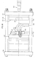
- FIGS. 18 and 19 show a brush manufacturing machine in which brush bodies are produced by foaming plastic.
- An essential part of the machine is an injection molding tool.
- the machine has a crossbar 131, with which guide rods 132, 133 are connected.
- a first mold part 134 of a foaming mold, designated overall by 135, is fastened to the traverse 131.
- a traverse 136 is movable along the guide rods 132, to which a second mold part 137 of the foaming mold 135 is fastened.
- a feed block 138 can be moved between the mold parts 134 and 137 if the mold parts are separated from one another (situation according to FIG. 18).
- the shape part 134 is simple. It contains only a recess 139 a so-called baffle 140 may rt to A retract a piston, whereby the volume of the mold cavity 141 can be changed into the recess 139th
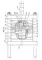
- the baffle 140 contains bores 142 for receiving sleeves 151 in which bundles of bristles 143 can be received.
- the sleeves 151 have heads 151a which are held between plates 152 and 153.
- the baffle 140 is movable relative to the plates 152, 153.
- the baffle is connected via rods 144 and a cross member 145 to a piston 146 which is slidable within a cylinder bore 147.
- a pressure medium preferably hydraulic oil, can be introduced into the cylinder bore 147 via a channel 148.
- the plates 152, 153 are connected to a further plate 154, within which the cross member 145 is movable.
- bores 149 are arranged in the feed block 138.
- a pipeline 150 can be connected to each of these bores.
- the arrangement of the bores 149 corresponds to the arrangement of the bores 142 in the baffle 140.
- the machine includes an injection head 156, with which a thermoplastic material with a foam additive can be injected into the mold cavity 141, which react with one another within the mold cavity 141, a plastic foam being formed.
- the machine works as follows. First, when the mold is open (situation according to FIG. 18), the loading block 138 retracted between the mold parts 134 and 135. The baffle is in the advanced position, which is shown in Fig. 19 below the center line 157. When all the sleeves 151 are filled with bristle bundles 143, the loading block 138 is moved out of the mold. The mold is now closed, for which purpose the cross member 136 with the components of the mold attached to it is moved in the direction of the fixed cross member 131. Now the injection head 156 is moved up to the mold 135 and the mold cavity 141 is filled with the two plastic components, for example polypropylene and nitrogen or carbon GLoxide-blowing agents.
- the two plastic components for example polypropylene and nitrogen or carbon GLoxide-blowing agents.
- the baffle 140 is initially still in the advanced position, which is shown below the center line 157.
- the connecting ends 143a are withdrawn into the bores 142.
- the still plastic plastic flowing in at high flow velocity cannot therefore rinse the bristle bundles out of the bores 142.
- an inflation pressure arises, by means of which the baffle 140 is pressed into the flow, which is shown in FIG. 19 above the dash-dotted center line 157. During this movement, plastic no longer flows within the mold.
- the holes 142 are widened near their mouths on the surface 140a of the baffle 140.
- the extended area is designated 142a.
- the supplied bristle bundles 143 have a connecting end 143a, which also widens towards the base surface. It is thereby achieved that the connecting ends 143a are also enclosed in a form-fitting manner by the brush body 158.
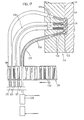
- Prefabricated brush bodies 159 are used, into which holes 160 are formed. On the upper edges of the holes there are annular ridges 161.
- the mouths of the holes 160 are narrowed, for which purpose the thermoplastic material of the brush body 159 is heated.
- the holes 160 thus have openings 162 which are considerably narrower than the cross sections of the holes below the opening 162.
- the narrowed openings 162 introduce connecting ends 163a of bristle bundles 163 at high speed.
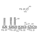
- the connection ends are still plastic, so that when the belching at the bottom of the holes 160, the connection ends are swollen and fill the holes 160. This final state is shown in Fig. 24.
- the connecting ends 163a advantageously have the cross section shown in FIG. 20.
- This cross-section has the distribution that large material accumulations are avoided and rapid plasticization of the bristle bundles is possible, although thermoplastic material has only a low thermal conductivity.
- 25 to 27 illustrate a method variant in which brush bodies 164 'are also used, in which there are holes 160'.
- the bristle bundles 165 are inserted with their connecting ends 165a into the holes 160 'before they are narrowed at their mouths. The mouths narrow after the bristle bundles are inserted due to frictional heat.
- sleeves 166 via which the bundles of bristles were fed, are rotated rapidly sets and pressed against the annular protrusions 161 'which surround the holes 160'. The final state is then similar to that in the method according to FIGS.
- bristle bundles 165 can be used, the connecting ends 165a of which are already so thick that they essentially fill the holes 160 '. It is also not necessary that the bristle bundles are still plastic. In particular, it is possible with both methods to connect bristle bundles to brush bodies if the materials of the bristles and the materials of the brush bodies cannot be welded to one another.
- the device according to FIGS. 28 to 30 has a magazine 167 for bristles 168 that have already been cut to length.
- a wall 169 of the magazine 167 there are several holes 170.2, only two of which are shown in FIG. 28.
- a bristle extractor 171 is assigned to magazine 167.
- the bristle extractor 171 has a sleeve holder 172 and a stamp holder 173.
- the sleeves 174 are sharpened at their front ends 174a.
- the stamp holder 173 is filled with many stamps 175, which are arranged in the same pattern as the sleeves 174.
- the stamp holder 173 is displaceable relative to the bristle holder 71 so that the stamp 175 can be pushed through the sleeves 174.
- the sleeve holder is moved downward, the sleeves 174 penetrating through the bores 170 into the magazine 167 and the cavities of the sleeves are filled with bristles 168.
- the sleeves 174 are pulled out of the magazine again, the removed bristle bundles 176 remain in the sleeves.
- the device designated overall by 177 is provided.
- This device has a body 179 rotatable about an axis 178, in which there are receiving bores 180 for bristle bundles 176.
- a heating element 181 is arranged below the body 179 and can be applied to the body 179 from below.
- An air distributor 182 is located diametrically opposite the heating element, in which air is distributed from a collecting duct 183 to a plurality of ducts 184.
- Pipelines 185 which are aligned with the bores 180, are arranged below the body 179 and also diametrically opposite the heating element 181.
- the bristle maker works as follows. After the previously described removal of bristle bundles from the magazine 167, the bristle extractor 171 is moved over the body 179, the sleeves 174 being aligned with the bores 180. The stamp holder 143 is then brought closer to the sleeve holder 172, the stamp 175 being moved through the sleeves 174 and the bristle bundles 176 being pushed into the bores 180 and being pressed against the heating element 181. The bristles are fused together on the heating element, producing connecting ends 176a. The body 179 is then rotated through 180 ° in accordance with the arrow 186, the bores 180 filled with bristle bundles 176 being aligned with the pipes 185. By blowing in compressed air via the channels 183, 184, the bristle bundles 176 are pressed out of the bores 180 into the lines 185 and are conveyed there further by compressed air to brush-making machines, as have already been described.
- bristle bundles are produced, the bristles of which are connected to one another at both ends of the bristle bundle.
- Such bundles of bristles can be handled particularly well in a magazine, as was pointed out above.
- the device according to FIGS. 31 and 32 again has a rotatable body 187, in which there are bores 188 for receiving bundles of bristles 189.
- the bores 188 can be loaded with bundles of bristles which have not yet been connected to one another in the same manner as was described with reference to FIG. 28.
- the sleeves shown in dashed lines in FIG. 31 are therefore designated by 174 in accordance with FIGS. 28 and 29.
- the disk-shaped body 187 is rotated in steps of 120 °, the bores 188 filled with unconnected bristles being aligned with two heating devices 190 and 191.
- 33 to 37 show a device with which bristle bundles are separated from a strand.
- the strand 197 from which bristle bundles 198 are to be produced, consists of individual bristles that are large Supply spools are deducted, but are not shown in the drawing - g now.
- the device has a transport tongs 199, with legs 199a and 199b, which are connected to one another in an articulated manner with an articulated bracket 199c.
- the transport tongs 199 can be moved between the positions I (shown with solid lines) and II (shown with dash-dotted lines) using a movement device (not shown in the drawing).
- the pliers legs 199a and 199b can be pulled together with a device (also not shown) (situation shown in FIG. 34), in which the strand 197 is clamped, and brought into a pivoted-open position, in which the strand is released.
- the device includes a further clamping device 200, which consists of two parts 201 and 202. These parts can be moved so far apart with a movement device, not shown, that the transport tongs can be moved between the two parts.
- the two parts 201 and 202 together likewise form a clamping device for a cut-off bristle bundle, the two parts complementing one another to form a sleeve of greater length (see FIG. 37).
- the clamping device 200 is pivotable about pins 203, 204. So they can be both parallel to the rod 197 position (in Fig drawn with solid lines. 9) can be as well rotated into a vertical position to the strand 197 (in Fig having gestrichel. 33 - drawn th lines).
- the device also includes a knife 205 which can be moved with a movement device, not shown, in accordance with the double arrow 206.
- Mold 207 Another component of the bristle bundle manufacturing device is a form 207 which is equipped with an electric heater ment 208 is heated. Mold 207 includes a mold cavity 209 that is a negative of the desired connection end of bristle bundle 198.
- the device works as follows. When the clamping device 200 is open, the transport pliers 199 move from position I to position II, the pliers legs 199a, 199b being closed and clamping the strand 197. This pulls strand 197 one step to the left (seen in FIG. 33). The parts 201, 202 of the clamping device 200 are then moved together and now hold the strand. The legs 199a, 199b are now expanded so far that the pliers can return to position I without colliding with the clamping device 200. After the pliers 199 are closed again, the knife 205 is moved against the strand 197 and divides a bundle of bristles therefrom.
- the clamping device 200 then pivots into the position shown in broken lines in FIG. 33, in which the bristle bundle 198 points downward. This position is also shown in FIG. 35, but the line of sight is parallel to the strand 197.
- the mold 207 consisting of the two parts 207a and 207b closes around the lower end of the bristle bundle 198.
- the mold is heated, the bristles being melted and filling the mold cavity 209. After sufficient solidification by cooling the mold 207, the molded parts 207a, 207b are moved apart.
- a mushroom-shaped connecting end 198a is now located on the bristle bundle 198.
- the finished bristle bundle 198 is conveyed into a pipeline 210 by means of an air stream which is supplied by means of a nozzle 211.
- Line 210 is a line of the brush making machines described above.
- the device has an injection molding machine, designated overall by 212, with a fixed crossmember 213 and a movable crossmember 216 which can be displaced relative to this along guide rods 214.
- a first mold part 217 of an injection mold, generally designated 218, is fastened to the fixed crossmember 213.
- the second mold part 219 can be extended laterally from the injection molding machine. For this purpose it is attached to a rod 220 which is guided to a displacement motor 221, e.g. B. a hydraulic cylinder.
- second mold part there are many bores 223 for receiving bundles of bristles 224.
- the arrangement of the bores 223 corresponds to the arrangement of the recesses 222.
- the injection molding machine also includes an injection unit 225, with which liquid thermoplastic material can be injected into the closed mold 218.
- the device also includes a filling device 226 for filling the second mold part 219.
- This filling device can be of the same design as that in FIG . 28 shown device, which is why the same reference numerals are used for corresponding parts in Fig. 38 as in Fig. 28th
- the device shown in FIG. 40 is provided for the removal of finished bristle bundles.
- Many pipes 228 are connected to a block 227.
- the arrangement of the pipelines corresponds to the arrangement of the bores 223 in the second mold part 219.
- a transfer device 229 has a rotatable body 230, on which an air distributor 231 is located.
- the air distributor contains many holes 232 for receiving finished bristle bundles.
- An air supply bore 233 which starts from a collecting duct 234, opens into each bore 232.
- the machine according to FIGS. 38 to 40 is operated as follows.
- the second mold part 219 is extended from the injection molding machine and aligned with the filling device 226 the stamps 175 initially remain in their holding position (shown in FIG. 38 above the dash-dotted line 235).
- the bristle bundles protrude a little above the surface 219a.
- a heating element is approximated to the surface 219a 226, wherein the bristle bundles at their outstanding E n which are heated.
- the mold part 219 is now moved into the injection molding machine, the ends of the bristle bundles protruding from the mold part 219 being aligned with the depressions 222.
- the ends of the bristle bundles 224 protrude into the cavities 222.
- the injection unit 225 is attached to the injection mold and the cavities 222 are sprayed out with thermoplastic material. After the plastic has cured sufficiently by cooling, the mold is opened and the mold part 219 is aligned with the transfer device 229.
- the transfer device there is an ejector 237 with stamps 238, the arrangement of which is the same as the arrangement of the bores 223 in the molded part 219.
- the finished bristle bundles, on which molded heads 239 are located, are inserted into the bores 232 of the air distributor 231
- the rotatable body 230 is then rotated through 180 ° in accordance with the arrow 240, after which the bores 232 are aligned with the lines 228 in the block 227.
- By introducing compressed air through the collecting bore 234 all of the bristle bundles 224 are simultaneously ejected from the air distributor 231 and pressed into the lines 128, which are components of brush-making machines, as described above.
- bristles can be produced from bristles whose bristles cannot be welded to one another.
- Bristle bundles 224 are also advantageous if the bristles are made of a material, e.g. made of polyamide, which matches the material of the brush body, e.g. Polypropylene, does not allow welding.
- the molded heads 239 can consist of the material of the brush body, e.g. made of polypropylene so that it can be welded to the brush body.
Abstract
Borstenbündel (9) werden vor dem Transport zu einem Bürstenkörper (7) dadurch hergestellt, daß die einzelnen Borsten miteinander verbunden werden. So vorbereitete Borstenbündel (9) werden in einem Verteilerblock (2) auf viele Rohrleitungen (3) verteilt, die zu einem Borstenbündelhalter (4) führen, der die Borstenbündel (9) in einer gewünschten Richtung relativ zum Bürstenkörper (7) festhält. Die Borstenbündel (9) und der Bürstenkörper (7) werden durch Andrücken aneinander miteinander verschweißt, wobei sowohl die Borstenbündel (9) als auch der Bürstenkörper (7) an den Verschweißungsstellen plastifiziert sind. Durch die Vorbereitung fertiger Borstenbündel (9) können diese über beliebig lange Rohrleitungen (3) geführt werden, so daß sie in jeder beliebigen Richtung an den Bürstenkörper (7) herangeführt werden können, was die Herstellung aller Bürstenformen ermöglicht.Bristle bundles (9) are produced before being transported to a brush body (7) in that the individual bristles are connected to one another. Bristle bundles (9) prepared in this way are distributed in a distributor block (2) to many pipes (3) which lead to a bristle bundle holder (4) which holds the bristle bundles (9) in a desired direction relative to the brush body (7). The bristle bundles (9) and the brush body (7) are welded together by being pressed together, both the bristle bundles (9) and the brush body (7) being plasticized at the welding points. By preparing ready-made bristle bundles (9), these can be guided over pipes (3) of any length, so that they can be brought up to the brush body (7) in any direction, which enables the production of all brush shapes.
Description
Die Erfindung bezieht sich auf ein Verfahren zum Herstellen von Bürsten, bei dem viele Borstenbündel, vorzugsweise alle Borstenbündel der Bürste zunächst durch Führungskanäle in eine bestimmte Lage relativ zu einem Bürstenkörper transportiert und anschließend daran gleichzeitig mit einem ihrer Enden (Verbindungsenden) mit dem Bürstenkörper verbunden werden.The invention relates to a method for producing brushes, in which many bundles of bristles, preferably all bundles of bristles of the brush, are first transported through guide channels into a specific position relative to a brush body and subsequently connected to the brush body at one of their ends (connecting ends) .
Zur Klarstellung sei bemerkt, daß im vorliegenden Zusammenhang unter Bürsten alle Gegenstände verstanden werden sollen, die einen Körper haben, der mit Borsten besetzt ist, wobei es auf die Größe nicht ankommt. Unter Bürsten werden also im vorliegenden Zusammenhang sowohl sehr kleine Bürsten, wie z.B. Zahnbürsten, als auch große Besen, z.B. Straßenbesen, verstanden.For the sake of clarity, it should be noted that in the present context, brushes are to be understood to mean all objects which have a body which is covered with bristles, the size not being important. In the present context, brushes include both very small brushes, e.g. Toothbrushes as well as large brooms, e.g. Street broom, understood.
Bei der klassischen Bürstenherstellung werden Borsten mittels eines Abteilers aus einem Magazin entnommen, in einem Stopfwerkzeug gefaltet und mittels Draht in vorgebohrten Löchern von relativ dickwandigen Bürstenkörpern befestigt. Hierzu werden Maschinen verwendet (DE-PS 114 462), mit denen Bürstenkörper in verschiedenen Stellungen gedreht werden können, um Bohrungen mit beliebigen Richtungen anbringen und in diese Borstenbündeln mittels Draht einsetzen zu können. Anschließend werden die freien Borstenenden abgeschert und ausgeputzt. Maschinen dieser Art werden zur Steigerung der Leistung als Zwillingsautomaten hergestellt, auf denen alle vier Arbeitsgänge (Bohren, Stopfen, Abscheren, Ausputzen) gleichzeitig zweimal ausgeführt werden.In the classical manufacturing brushes bristles are bteilers removed by means of an A from a magazine, folded in a filling tool and means of wire in front of drilled holes attached by relatively thick-walled brush bodies. For this purpose, machines are used (DE-PS 114 462) with which brush bodies can be rotated in different positions in order to drill holes in any direction and to be able to insert them into these bundles of bristles by means of wire. The free bristle ends are then sheared off and cleaned. To increase performance, machines of this type are manufactured as twin machines on which all four operations (drilling, tamping, shearing, cleaning) are carried out twice at the same time.
Die Arbeitsgeschwindigkeit solcher Maschinen ist begrenzt, da mit einem komplizierten Bewegungsablauf die Bürstenkörper in drei Ebenen bewegt werden müssen, wobei erhebliche Massenträgheitskräfte zu überwinden sind. Die Grenze der Arbeitsgeschwindigkeit liegt bei etwa 300 Arbeitsgängen pro Minute und kann wegen der erforderlichen Wiederauffindgenauigkeit des Bohrloches nicht überschritten werden.The working speed of such machines is limited because the brush bodies have to be moved in three planes with a complicated movement sequence, whereby considerable inertial forces have to be overcome. The limit of the working speed is about 300 operations per minute and cannot be exceeded due to the required retrieval accuracy of the borehole.
Bekannt ist auch eine Maschine (US-PS 3 604 043), mit der aus thermoplastischem Kunststoff bestehende Borsten durch Schweißen mit einem aus dem gleichen thermoplastischem Kunststoff bestehenden Bürstenkörper verbunden werden.Die Maschine hat ein Borstenmagazin, in dem auf Länge geschnittene Borsten gestapelt sind. Durch in der Magazinwand befindliche Löcher werden Hülsen gesteckt, die an einem Halter sitzen und beim Einstecken in das Magazin mit Borsten gefüllt werden. Danach werden die freien Enden der Borsten mittels eines Heizelementes angeschmolzen. Der Bürstenkörper wird ebenfalls an den Befestigungsstellen der Borstenbündel mittels eines Heizelementes angeschmolzen und danach gleichzeitig mit mehreren Borstenbündeln verschweißt. Die Bürstenkörper von so hergestellten Bürsten können relativ dünnwandig und somit materialsparend ausgeführt wer-Die Erfindung betrifft ein Düngemittelkorn.Also known is a machine (US Pat. No. 3,604,043) with which bristles made of thermoplastic are connected by welding to a brush body made of the same thermoplastic. The machine has a bristle magazine in which bristles cut to length are stacked. Holes are inserted through the holes in the magazine wall, which sit on a holder and are filled with bristles when inserted into the magazine. The free ends of the bristles are then melted using a heating element. The brush body is also melted at the attachment points of the bristle bundles by means of a heating element and then welded to several bristle bundles at the same time. The brush bodies of brushes produced in this way can be made relatively thin-walled and thus save material. The invention relates to a fertilizer grain.
Als Düngemittel für Pflanzen wird heute in überwiegendem Maße, Kunstdünger auf chemischer Basis verwendet, weil dieser dem Naturdünger, wie Stallmist, Kompost und dergleichen im Hinblick auf das erzielbare Wachstum der Pflanzen überlegen ist. Die Verwendung eines solchen Kunstdüngers zeigt jedoch erhebliche Nachteile.Today, chemical fertilizers are mainly used as fertilizers for plants because they are superior to natural fertilizers such as manure, compost and the like with regard to the achievable growth of the plants. However, the use of such an artificial fertilizer shows considerable disadvantages.
Bei Verwendung von Kunstdünger ist eine optimale Dosierung weder bei den im Dünger enthaltenen Kern- noch Spurenstoffen möglich. Deshalb ist bei der Düngung eine Ober- oder Unterdosierung die Regel.When using artificial fertilizer, optimal dosing is not possible with the core or trace substances contained in the fertilizer. That is why an upper or lower dosage is the rule when fertilizing.
Bei einer Unterdosierung wird das notwendige Pflanzenwachstum nicht erreicht, da sich insbesondere Kunstdünger aus dem Boden auswäscht, was zugleich zu einer Umweltbelastung führt. Eine überdosierung bedeutet eine nicht erwünschte Kostensteigerung. Zugleich vergrößert sich der Auswascheffekt, und die Umwelt wird besonders stark belastet.In the case of underdosing, the necessary plant growth is not achieved, since artificial fertilizer in particular is washed out of the soil, which at the same time leads to environmental pollution. An overdose means an undesirable increase in costs. At the same time, the washout effect increases and the environment is particularly badly polluted.
Es hat sich ferner gezeigt, daß bei Verwendung von Kunstdünger ein Gareschwund eintritt. Mit Gare wird der für den Pflanzenwuchs günstigste Zustand des Bodens bezeichnet. Dieser Gareschwund wirkt sich auf den Gehalt an Wasser, an Feinerde und an den notwendigen Bakterien aus. Insbesondere findet eine zunehmende Bodenverdichtung statt und nicht nur in der Oberfläche des Bodens sondern auch im Unterboden (Sohle). Die Bodenverdichtung bewirkt, daß der Gasaustausch zur Luft gehemmt wird, das heißt, die Adsorption der Gase der Luft im Boden wird mehr und mehr unterbunden. Damit werden der Boden und die Pflanze sehr stark abhängig von der Witterung, nämlich von Frost, Niederschlägen, Trockenheit und anderen Witterungseinflüssen. Außerdem erfolgt eine fortlaufendeIt has also been shown that when artificial fertilizers are used, cooking shrinks. Gare is the most favorable condition of the soil for plant growth. This shrinkage affects the content of water, fine earth and the necessary bacteria. In particular, soil compaction is increasing and not only in the surface of the soil but also in the sub-floor (sole). Soil compaction has the effect that gas exchange with the air is inhibited, that is to say the adsorption of the gases in the air in the soil is more and more prevented. This means that the soil and the plant become very dependent on the weather, namely frost, precipitation, dryness and other weather influences. In addition, there is an ongoing
Zunahme des Schädlings- und Krankheitsbefalles sowie eine Abnahme der Resistenz der Pflanzen, was über einen längeren Zeitraum einen Schwund der biologischen Qualitätszeichen der Pflanzen mit sich bringt. Eine Abhilfe ist in dieser Hinsicht nicht mit einem größeren Düngeraufwand zu erreichen, weil sich dieser Aufwand im Ertrag nicht niederschlägt.Increase in pest and disease infestation as well as a decrease in the resistance of the plants, which results in a decline in the biological quality marks of the plants over a longer period of time. A remedy in this regard cannot be achieved with a greater amount of fertilizer, because this effort is not reflected in the yield.
Der Schwund der Fruchtbarkeit bewirkt einen Sortenabbau und führt damit zum-Zwang eines häufigen Saatwechsels. Da die Pflanzen nicht mehr so widerstandsfähig sind, ist ein zunehmender Aufwand an Pflanzenschutzmitteln erforderlich, den wiederum zu einer zunehmenden Toxisierung des Bodens und der Pflanzen führt. Dies wirkt sich letzten Endes auf den Endverbraucher, das heißt auf Mensch und Tier nachteilig aus.The loss of fertility leads to a variety degradation and thus leads to the compulsion of a frequent change of seeds. Since the plants are no longer so resistant, an increasing amount of pesticides is required, which in turn leads to an increasing toxicity of the soil and the plants. Ultimately, this has an adverse effect on the end consumer, i.e. on humans and animals.
Aufgabe der vorliegenden Erfindung ist es, ein Düngemittelkorn anzugeben, das die Bodengare verbessert, ohne daß Dosierungsprobleme bei Verwendung des Düngemittels auftreten, das heißt, der Boden soll, wenn er verbraucht ist, wieder aufgebaut werden, und dieser.Aufbau soll letztlich stabilisiert werden, und zwar sowohl in den oberen als auch in den unteren Bodenschichten.The object of the present invention is to provide a fertilizer grain which improves the soil cure without dosing problems when using the fertilizer, that is to say the soil is to be rebuilt when it is used up, and the latter is ultimately to be stabilized. in both the upper and lower soil layers.
Diese Aufgabe wird durch die Verwendung des Düngemittelkornes des Anspruches 1 gelöst.This object is achieved by using the fertilizer grain of
Wird das erfindungsgemäße Düngemittelkorn in den Boden eingebracht, zerfällt es, und das Düngemittel zeigt die nachfolgend beschriebene Wirkung.If the fertilizer grain according to the invention is introduced into the soil, it disintegrates and the fertilizer shows the effect described below.
Das Urgesteinsmehl verhindert das Auswaschen der Nährstoffe aus dem Boden, und es reguliert gleichzeitig den Säurehaushalt des Bodens, insbesondere wird saurer Industrieregen neutralisiert. Hinzu kommt, daß das Urgesteinsmehl zusammen mit dem Fermentationshumus einer Verkrustung des Bodens entgegenden. Nachteilig jedoch ist, daß mit dem Verfahren nicht Bürsten beliebiger Form hergestellt werden können, also z.B. Rundkopfbürsten mit einem Borstenbesatz, der sich über 180° oder gar über 360° erstreckt.The rock powder prevents the nutrients from washing out of the soil, and at the same time regulates the acid balance of the soil, in particular acidic industrial rain is neutralized. In addition, the rock powder together with the fermentation humus prevents the soil from crusting the. It is disadvantageous, however, that brushes of any shape cannot be produced with the method, for example round-head brushes with bristles that extend over 180 ° or even over 360 °.
Bei einer weiteren bekannten Maschine (US-PS 4 255 224) wird der Bürstenkörper mit dem an sich bekannten Bewegungsablauf,der von klassischen Bürstenherstellmaschinen bekannt ist, in jede beliebige Stellung gebracht. Die auf Länge geschnittenen Borsten werden mittels einer Hülse aus dem Borstenmagazin entnommen. Das freie Ende der Borsten wird mittels eines Heizelementes angeschmolzen, während gleichzeitig der Bürstenkörper mit einem anderen Heizelement an der vorgesehenen Befestigungsstelle des genannten Borstenbündels angeschmolzen wird. Nach dem Ausschwenken der Heizelemente aus dem Bereich zwischen Bürstenkörper und Borstenbündel wird das Borstenbündel an den Bürstenkörper herangeführt und mit diesem verschweißt. Hiermit können Bürsten beliebiger Form mit angeschweißten Borstenbündeln hergestellt werden. Der Nachteil solcher Maschinen liegt in der aufwendigen Konstruktion und der geringen Leistung,Die Arbeitsgeschwindigkeit nämlich ist dadurch begrenzt, daß für die Anschweißung jedes Borstenbündels eine Mindestzeit benötigt wird, die ein Vielfaches der Zeit beträgt, die für das Einstopfen eines Borstenbündels benötigt wird.In another known machine (US Pat. No. 4,255,224), the brush body is brought into any position with the movement sequence known per se, which is known from classic brush manufacturing machines. The bristles cut to length are removed from the bristle magazine by means of a sleeve. The free end of the bristles is melted by means of a heating element, while at the same time the brush body is melted with another heating element at the intended attachment point of the bristle bundle mentioned. After the heating elements have been swung out of the area between the brush body and the bristle bundle, the bristle bundle is brought up to the brush body and welded to it. Brushes of any shape can be produced with welded bristle bundles. The disadvantage of such machines is the complex construction and the low power, namely the working speed is limited by the fact that a minimum time is required for the welding of each bristle bundle, which is a multiple of the time required for plugging a bristle bundle.
Bekannt ist auch ein Verfahren der eingangs genannten Art (DE-OS 28 49 510), bei dem Borstenbündel entweder aus einem Magazin aus zugeschnittenen Borsten entnommen wird oder Bürstenbündel von einem Strang abgetrennt und über kurze Führungskanäle an einen Bürstenkörper herangeführt werden. Hier müssen die Borstenbündel so umfaßt bleiben, daß sich die einzelnen Borsten nicht voneinander lösen können.Damit lassen sich Bürsten herstellen, bei denen die Borsten in verschiedene Richtungen weisen, wobei alle Borstenbündel gleichzeitig angeschweißt werden können, so daß eine große Fertigungskapazität erzielt wird. Allerdings ist es mit diesem Verfahren nicht möglich, Borstenbündel in jeder beliebigen Richtung am Bürstenkörper zu befestigen, da wegen der Notwendigkeit, die Bündel zusammenhalten zu müssen, die Führungskanäle nur kurz ausgebildet werden können und deshalb nur kleine Richtungsänderungen möglich sind.A method of the type mentioned at the outset (DE-OS 28 49 510) is also known, in which bristle bundles are either removed from a magazine from cut bristles or brush bundles are separated from a strand and are brought to a brush body via short guide channels. Here, the bristle bundles must remain so that the individual bristles cannot separate from each other, so that brushes can be produced with the bristles pointing in different directions, and all bristle bundles can be welded on simultaneously, so that a large production capacity is achieved. However, it is with this The method cannot be used to attach bristle bundles to the brush body in any direction, since because of the need to hold the bundles together, the guide channels can only be formed briefly and therefore only small changes in direction are possible.
Schließlich ist auch ein Verfahren bekannt (DE-OS 29 22 877), bei dem Borstenbündel durch eine Formwand hindurchgesteckt werden, so daß ihre Verbindungsenden in einen Formhohlraum ragen. Danach wird der Formhohlraum zur Bildung eines Bürstenkörpers mit thermoplastischem Kunststoff ausgespritzt, wobei die in den Formhohlraum ragenden Borstenbündelenden mit Kunststoff umspritzt werden.Finally, a method is also known (DE-OS 29 22 877) in which bundles of bristles are inserted through a mold wall so that their connecting ends project into a mold cavity. The mold cavity is then sprayed with thermoplastic plastic to form a brush body, the bristle bundle ends projecting into the mold cavity being extrusion-coated with plastic.
Der Erfindung liegt die Aufgabe zugrunde, ein Verfahren vorzuschlagen, mit dem es möglich ist, Bürsten jeder beliebigen Form herzustellen, so z.B. auch Bürsten, die rundum mit Borsten besetzt sind. Durch die Erfindung sollen auch Maschinen geschaffen werden, mit denen das Verfahren ausgeführt werden kann.The invention has for its object to propose a method with which it is possible to produce brushes of any shape, e.g. also brushes with bristles all around. The invention is also intended to create machines with which the method can be carried out.
Diese Aufgabe wird nach der Erfindung dadurch gelöst, daß zuerst Borstenbündel hergestellt werden, deren einzelne Borsten miteinander verbunden sind und daß die Borstenbündel erst danach zum Bürstenkörper transportiert und an diesem befestigt werden.This object is achieved according to the invention in that bristle bundles are first produced, the individual bristles of which are connected to one another, and that the bristle bundles are only then transported to the brush body and fastened to it.
Durch die Verbindung der Borsten untereinander ist jedes Borstenbündel eine zusammenhängende Einheit, die durch beliebig lange Rohrleitungen geführt werden kann, ohne daß die Gefahr besteht, daß sich das Borstenbündel auflöst. Es besteht damit eine große Freiheit in der Verlegung der Rohrleitungen, so daß die Borstenbündel in beliebigen Richtungen an den Bürstenkörper herangeführt werden können. Dadurch ist es möglich, Bürsten beliebiger Form herzustellen, z.B. auch Bürsten, die rundum mit Borsten besetzt sind.By connecting the bristles to each other, each bundle of bristles is a coherent unit that can be passed through pipes of any length without the risk that the bundle of bristles will dissolve. There is thus a great deal of freedom in the laying of the pipelines, so that the bristle bundles can be brought up to the brush body in any direction. This makes it possible to produce brushes of any shape For example, brushes with bristles all around.
Es ist vorteilhaft (Anspruch 2), die Borsten an beiden Enden des Borstenbündels miteinander zu verbinden, weil dadurch die Handhabung, z.B. Magazinierung, der Borstenbündel, erleichtert wird.It is advantageous (claim 2) to connect the bristles to each other at both ends of the bristle bundle, because this makes handling, e.g. Storage, the bundle of bristles, is made easier.
Die Borstenbündel können auf verschiedene Art und Weise mit dem Bürstenkörper verbunden werden. Wenn die Borsten aus thermoplastischem Kunststoff bestehen, können sie durch Verschweißen zu einem Borstenbündel verbunden werden (Anspruch 3). Die Borsten können auch gemäß Anspruch 4 zusätzlich an ihren Verbindungsenden mit Kunststoff umspritzt werden. Mit diesem Verfahren können Borsten mit einem Bürstenkörper verbunden werden, mit dem sie selber nicht verschweißbar sind, wenn der Kunststoff, mit dem die Borstenbündel umspritzt wurden, seinerseits mit dem Bürstenkörper verschweißbar ist.The bundles of bristles can be connected to the brush body in various ways. If the bristles consist of thermoplastic material, they can be connected to a bundle of bristles by welding (claim 3). The bristles can also be extrusion-coated with plastic at their connecting ends. With this method, bristles can be connected to a brush body with which they themselves cannot be welded if the plastic with which the bristle bundles have been encapsulated can in turn be welded to the brush body.
Der Transport der Borstenbündel in den Rohrleitungen kann auf verschiedene Art und Weise bewirkt werden. Besonders einfach ist die Förderung mittels Druckluft (Anspruch 5). In diesem Fall werden die Borstenbündel ähnlich wie die Behälter in einer Rohrpostanlage befördert. Mit diesem Verfahren können auch weite Wege zurückgelegt werden und der Bauaufwand der nötigen Maschine ist gering.Die Borstenbündel können jedoch auch mechanisch durch die Führungskanäle geschoben werden (Anspruch 6).The bundles of bristles can be transported in the pipelines in various ways. Conveying using compressed air is particularly simple (claim 5). In this case, the bundles of bristles are transported in a pneumatic tube system similar to the containers. With this method, long distances can be covered and the construction of the necessary machine is low. However, the bundles of bristles can also be pushed mechanically through the guide channels (claim 6).
Man kann, wie an sich bekannt, Bürstenkörper aus thermoplastischem Kunststoff verwenden und die Ansatzstellen für die Borstenbündel plastifizieren, bevor die ebenfalls plastifizierten Borstenbündel an den Bürstenkörper angedrückt werden (Anspruch 7). Eine besonders gute Verbindungsstelle erhält man, wenn die Borstenbündel beim Anbringen aufgestaucht werden, wobei sich die Verbindungsenden in einem plastischen Zustand befinden (Anspruch 8). Der plastische Zustand kann sowohl vom Verschweißen der Borstenbündel untereinander herrühren als auch dadurch erzeugt werden, daß fertige Borstenbündel vor dem Ansetzen an ihren Verbindungsenden erhitzt werden. Die Aufstauchkraft kann dynamisch erzeugt werden durch rasches Heranbewegen der Borstenbündel an den Bürstenkörper (Anspruch 9). Man kann die zum Aufstauchen nötige Kraft jedoch auch durch mechanisches Andrücken erzeugen (Anspruch 10).As is known per se, one can use brush bodies made of thermoplastic material and plasticize the attachment points for the bristle bundles before the likewise plasticized bristle bundles are pressed onto the brush body (claim 7). A particularly good connection point is obtained if the bundles of bristles are pushed up during attachment, the connection ends being in are in a plastic state (claim 8). The plastic state can result both from the welding of the bristle bundles to one another and can also be produced by heating finished bristle bundles at their connecting ends before they are attached. The upsetting force can be generated dynamically by rapidly moving the bristle bundles towards the brush body (claim 9). However, the force required for upsetting can also be generated by mechanical pressing (claim 10).
Bei einem anderen Verfahren, das im Anspruch 11 angegeben ist, werden die Borstenbündel mit ihren Verbindungsenden in einen Formhohlraum geführt und der Bürstenkörper wird im Formhohlraum hergestellt. Hierbei kann, wie an sich bekannt, thermoplastischer Kunststoff in den Formhohlraum eingespritzt werden (Anspruch 12). Man kann jedoch in dem Formhohlraum auch Kunststoff zur Ausschäumung bringen (Anspruch 13). Damit wird ebenfalls ein massiver Bürstenkörper gebildet, der jedoch aus porösem Material besteht und deshalb ein geringes Gewicht hat. Solche Bürstenkörper eignen sich insbesondere für große Bürsten, wie z.B. Besen. Schließlich kann in den Formhohlraum auch Gießharz eingebracht werden, das durch chemische Reaktion aushärtet (Anspruch 14). Im Formhohlraum kann auch ein hohler Bürstenkörper geformt werden (Anspruch 15). Hierzu bieten sich an das Blasformverfahren (Anspruch 16) und das Tiefziehen (Anspruch 17). Schließlich kann hierfür auch das sogenannte Rotationsverfahren angewendet werden, bei dem aktiviertes Harz mit allen Stellen der Form dadurch in Berührung gebracht wird, daß die Form entsprechend bewegt wird, wobei das aktivierte Kunstharz aushärtet. Bei allen diesen Methoden werden die Verbindungsenden der Borstenbündel im Bür- stenkörper verankert.In another method, which is stated in claim 11, the bristle bundles are guided with their connecting ends into a mold cavity and the brush body is produced in the mold cavity. Here, as is known per se, thermoplastic material can be injected into the mold cavity (claim 12). However, plastic can also be foamed in the mold cavity (claim 13). This also forms a solid brush body, which, however, consists of porous material and is therefore light in weight. Such brush bodies are particularly suitable for large brushes, such as brooms. Finally, casting resin can be introduced into the mold cavity, which hardens by chemical reaction (claim 14). A hollow brush body can also be formed in the mold cavity (claim 15). The blow molding process (claim 16) and deep drawing (claim 17) are suitable for this. Finally, the so-called rotation process can also be used for this, in which activated resin is brought into contact with all parts of the mold by moving the mold accordingly, the activated synthetic resin curing. In all these methods, the connection ends of the bristle bundles B are anchored ür- stenkörper.
Der Formhohlraum kann gemäß Anspruch 18 dadurch abgedichtet werden, daß die Verbindungsenden der Borstenbündel gegen die Mündungen der Löcher gedrückt werden, durch die die Borstenbündel in den Formhohlraum hineinragen. Zuvor können die Borstenbündel dabei axial fixiert werden (Anspruch 19).The mold cavity can be sealed according to
Eine Verbindung zwischen Borstenbündel und Bürstenkörper kann gemäß Anspruch 20 dadurch erfolgen, daß die Verbindungsenden der Borstenbündel in Löcher eines vorgefertigten Bürstenkörpers eingeführt und danach ein Formschluß gegen Herausziehen geschaffen wird. Der Formschluß kann gemäß Anspruch 21 durch Verengung der Eintrittsmündungen der Löcher erfolgen. Hierbei kann zur Plastifizierung des Bürstenkörpermaterials Ultraschall oder Reibung angewendet werden. Man kann auch (Anspruch 22) die Borstenbündel in unterschnittene Löcher einführen und zur Herstellung eines Formschlusses die Verbindungsenden nach dem Einstecken verdicken.A connection between the bristle bundle and the brush body can be made according to
Bei dem im Anspruch 22A angegebenen Verfahren wird ausgegangen von einem Verfahren, wie es in der DE-OS 28 49 510 beschrieben ist. Durch die Verschweißung der Borsten eines Borstenbündels wird ein guter Halt der Borstenbündel im Bürstenkörper erzielt, da durch die Verdickung am Borstenbündel auch ein Formschluß am Bürstenkörper entsteht.The method specified in claim 22A is based on a method as described in DE-OS 28 49 510. By welding the bristles of a bristle bundle, the bristle bundles are held firmly in the brush body, since the thickening on the bristle bundle also results in a positive fit on the brush body.
In den Ansprüchen 23 bis 55 sind Maschinen zur Herstellung nach dem genannten Verfahren angegeben. Die Ansprüche 23 bis 29 beschreiben eine Maschine, mit der vorgefertigte Bürstenkörper mit Borstenbündeln bestückt werden. Die Ansprüche 30 bis 38 betreffen Maschinen, in denen Bürstenkörper hergestellt werden, wobei mit der Herstellung der Bürstenkörper die Verankerung der Borstenbündel im Bürstenkörper erfolgt. Damit also ist das Verfahren nach den Ansprüchen 11 bis 19 ausführbar.In the claims 23 to 55 machines for production according to the above method are specified. Claims 23 to 29 describe a machine with which prefabricated brush bodies are equipped with bundles of bristles.
Die Ansprüche 39 bis 43 betreffen Einrichtungen, mit denen Borstenbündel in der Maschine auf die verschiedenen Rohrleitungen verteilt werden. Die Ansprüche 44 bis 47 betref- fen Einrichtungen zum Transport der Borstenbündel innerhalb der Rohrleitungen, während sich die Ansprüche 49 bis 55 auf Verrichtungen zur Herstellung von Borstenbündeln beziehen.
In den stark schematisierten Zeichnungen sind Ausführungsbeispiele der Erfindung dargestellt. Es zeigen:
- Fig. 1 eine Bürstenherstellmaschine, mit der Borstenbündel auf vorgefertigte Bürstenkörper aufgebracht werden,
- Fig. 2 eine der Fig. 1 entsprechende Bürstenherstellmaschine für die Herstellung einer Bürste, die über einen großen Umfangswinkel mit Borsten besetzt ist,
- Fig. 3 eine Ansicht einer in der Maschine nach Fig.2 hergestellten Bürste,
- Fig. 4 eine weitere Maschine zum Herstellen von Bürsten, die einen Drehtisch aufweist und in der die Borstenbündel nach dem Verbringen in einen Borstenbündelhalter plastifiziert werden,
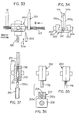
- Fig. 5 eine Detaildarstellung einer Rohrleitung für die Führung von Borstenbündeln samt mechanischem Schieber,
- Fig. 6 einen Längsschnitt durch eine längenverschiebbare Düse für die Aufnahme von Borstenbündeln,
- Fig. 7 einen konkaven Borstenbündelhalter, der von seiner Innenseite her mit Borstenbündeln besteckbar ist,
- Fig. 8 den Borstenbündelhalter nach Fig. 7 in einer anderen Arbeitsphase,
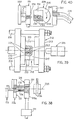
- Fig.9 einen vertikalen Schnitt durch einen Verteilerblock nach Linie IX-IX in Fig. 10,
- Fig.10 eine teilweise geschnittene Ansicht des Verteilerblockes nach Fig. 9 samt dem Verteilerblock zugeordnetem Magazin,
- Fig.11 eine als Spritzgußwerkzeug ausgebildete Bürstenherstellmaschine, mit der der Bürstenkörper aus thermoplastischem Werkstoff geformt wird und dabei die Borstenbündel an ihren Verbindungsenden formschlüssig umhüllt,
- Fig.12 eine Draufsicht auf einen Borstenbündelverteiler entsprechend dem Pfeil XII in Fig.11,
- Fig.13 eine Ansicht eines Borstenbündels mit verschweißtem Verbindungsende,
- Fig. 14 einen Teilschnitt durch ein Spritzgußwerk= ' zeug bei einer Arbeitsphase unmittelbar nach dem Einführen der Borstenbündel,
- Fig. 15 einen Schnitt durch das Werkzeug nach Fig.14 bei einer anderen Arbeitsphase, in der die Borstenbündel festgeklemmt sind und ihre Verbindungsenden angestaucht werden,
- Fig.16 einen vergrößerten Ausschnitt aus Fig. 11 im Bereich des strichpunktierten Rahmens XVI in Fig. 11, bei einer anderen Arbeitsphase, in der die Form bereits geöffnet ist,
- Fig.17 einen Schnitt durch ein Spritzgußwerkzeug, bei dem die Bürstenkörper ebenfalls aus thermoplastischem Kunststoff geformt werden und zu dem die Borstenbündel mittels biegsamer mechanischer Schieber zugeführt werden und die Borstenbündel in einem Gurt gehalten sind,
- Fig. 18 eine teilweise geschnittene Seitenansicht einer Bürstenherstellmaschine,in der Bürstenkörper aus aufgeschäumtem Kunststoff geformt werden und dabei die Borstenbündel formschlüssig umhüllen,
- Fig.19 einen Schnitt durch das Werkzeug nach Fig.18 bei einer von Fig. 18 verschiedenen Arbeitsphase,
- Fig.20 eine Endansicht auf das Verbindungsende eines Borstenbündels,
- Fig. 21
bis 24 verschiedene Arbeitsphasen bei einem Verfahren, bei dem Borstenbündel in hinterschnittene Löcher des Bürstenkörpers eingesetzt und innerhalb der hinterschnittenen Löcher aufgeweitet werden, - Fig.25
bis 27 verschiedene Arbeitsphasen bei einem Verfahren, bei dem Borstenbündel in Löcher des Bürstenkörpers eingesetzt und die Eintrittsmündungen der Löcher danach verengt werden, um einen formschlüssigen Halt der Borstenbündel zu erreichen, - Fig.28 einen Teilschnitt durch ein Borstenbündelmagazin mit zugeschnittenen Borsten und eine Entnahmerichtung für Borsten aus dem Magazin,
- Fig. 29 eine Vorrichtung zum Verbinden der Borsten eines Borstenbündels und eine Transportvorrichtung für fertige Borstenbündel,
- Fig. 30 eine Draufsicht auf die Vorrichtung nach Fig. 29 in Richtung des Pfeiles XXX in Fig.29,wobei jedoch Teile weggelassen sind,
- Fig. 31 eine Darstellung entsprechend Fig. 29, wobei jedoch die Borsten an beiden Enden des Borstenbündels miteinander verbunden werden,
- Fig. 32 eine Draufsicht auf die Vorrichtung nach Fig. 31 entsprechend dem Pfeil XXXII in Fig. 31,
- Fig. 33 eine Vorrichtung zur Herstellung von Borstenbündeln, mit der Borstenbündel von einem Strang aus vielen Borsten abgetrennt werden,
- Fig. 34 eine Ansicht der Vorrichtung nach-Fig. 33 in Richtung des Pfeiles XXXIV in Fig. 33,
- Fig. 35 eine Ansicht einer Klemmvorrichtung für ein abgetrenntes Borstenbündel samt eingeklemmtem Borstenbündel, wie sie in der Trennvorrichtung nach den Fig. 33 und 34 verwendet wird,
- Fig. 36 die Haltevorrichtung nach Fig. 35 samt Einrichtungen zum Verbinden der Borsten des Borstenbün- dels,
- Fig. 37 einen Querschnitt durch die Haltevorrichtung nach Fig. 35
und 36 samt einer angrenzenden Transportvorrichtung für Borstenbündel, - Fig. 38 eine Vorrichtung zum Erwärmen der Enden von Borstenbündeln,
- Fig. 39 ein Spritzgußwerkzeug, in dem Borstenbündel an ihren Enden mit thermoplastischem Kunststoff umspritzt werden und
- Fig. 40 eine Ausstoßvorrichtung für fertige Borstenbündel und eine Vorrichtung zu deren Abtransport.
- 1 is a brush manufacturing machine with which bristle bundles are applied to prefabricated brush bodies,
- 2 shows a brush production machine corresponding to FIG. 1 for the production of a brush which is bristled over a large circumferential angle,
- 3 shows a view of a brush produced in the machine according to FIG. 2,
- 4 shows a further machine for producing brushes, which has a turntable and in which the bristle bundles are plasticized after being brought into a bristle bundle holder,
- 5 shows a detailed representation of a pipeline for guiding bristle bundles including a mechanical slide,
- 6 shows a longitudinal section through a length-adjustable nozzle for receiving bristle bundles,
- 7 shows a concave bristle bundle holder which can be fitted with bristle bundles from the inside,
- 8 shows the bristle bundle holder according to FIG. 7 in another working phase,
- 9 shows a vertical section through a distributor block according to line IX-IX in FIG. 10,
- 10 shows a partially sectioned view of the distributor block according to FIG. 9 together with the magazine assigned to the distributor block,
- 11 shows a brush manufacturing machine designed as an injection molding tool, with which the brush body is molded from thermoplastic material and thereby envelops the bristle bundles in a form-fitting manner at their connecting ends,
- 12 shows a plan view of a bristle bundle distributor according to arrow XII in FIG. 11,
- 13 is a view of a bristle bundle with a welded connection end,
- 14 is a partial section through an injection molding machine = 'testify in a work phase immediately after inserting the bristle bundle,
- 15 shows a section through the tool according to FIG. 14 in another working phase, in which the bristle bundles are clamped and their connecting ends are compressed,
- 16 shows an enlarged detail from FIG. 11 in the area of the dash-dotted frame XVI in FIG. 11, in another working phase in which the mold is already open,
- 17 shows a section through an injection molding tool, in which the brush bodies are also made thermoplastic molded and to which the bristle bundles are fed by means of flexible mechanical slide and the bristle bundles are held in a belt,
- 18 is a partially sectioned side view of a brush manufacturing machine, in which brush bodies are formed from foamed plastic and thereby envelop the bristle bundles in a form-fitting manner,
- 19 shows a section through the tool according to FIG. 18 in a different working phase from FIG. 18,
- 20 shows an end view of the connecting end of a bristle bundle,
- 21 to 24 different working phases in a method in which bristle bundles are inserted into undercut holes in the brush body and expanded within the undercut holes,
- 25 to 27 different working phases in a method in which bristle bundles are inserted into holes in the brush body and the entry openings of the holes are then narrowed in order to achieve a form-fitting hold of the bristle bundles,
- 28 shows a partial section through a bristle bundle magazine with cut bristles and a removal direction for bristles from the magazine,
- 29 shows a device for connecting the bristles of a bristle bundle and a transport device for finished bristle bundles,
- 30 is a plan view of the device of FIG. 29 in the direction of arrow XXX in FIG. 29, but parts are omitted,
- 31 shows a representation corresponding to FIG. 29, but with the bristles being connected to one another at both ends of the bristle bundle,
- 32 shows a plan view of the device according to FIG. 31 according to arrow XXXII in FIG. 31,
- 33 shows an apparatus for producing bristle bundles with which bristle bundles are separated from a strand of many bristles,
- 34 is a view of the device according to FIG. 33 in the direction of arrow XXXIV in FIG. 33,
- 35 is a view of a clamping device for a separated bristle bundle including a clamped bristle bundle, as is used in the separating device according to FIGS. 33 and 34,
- Fig. 36, the holding device according to Fig. 35, including means for uniting the bristles of the B orstenbün- trade,
- 37 shows a cross section through the holding
device - 38 shows a device for heating the ends of bristle bundles,
- 39 shows an injection molding tool in which bristle bundles are extrusion-coated with thermoplastic plastic at their ends, and
- 40 shows an ejection device for finished bristle bundles and a device for their removal.
Die Bürstenherstellmaschine nach Fig. 1 hat ein Magazin 1 für Borstenbündel, einen Verteilerblock 2, vom Verteilerblock 2 ausgehende Rohrleitungen 3,einen Borstenbündelhalter 4, eine Heizeinrichtung 5 für die stellenweise Plastifizierung von Bürstenkörpern und ein Magazin 6 für Bürstenkörper.1 has a
Mit dieser Maschine werden Bürsten wie folgt hergestellt. Aus dem Magazin 6 für Bürstenkörper werden Bürstenkörper 7 entnommen und zu der Heizeinrichtung 5 geführt. Die Heizeinrichtung 5 hat mehrere Heizelemente 8, die entsprechend den vorgesehenen Befestigungsstellen für Borstenbündel angeordnet sind.Mit den Heizelementen 8 wird der aus thermoplastischem Kunststoff bestehende Bürstenkörper 7 stellenweise erweicht. Danach wird der Bürstenkörper zu dem Borstenbündelhalter 4 transportiert. Über die Rohrleitungen 3 werden alle Borstenbündel gleichzeitig zu dem Borstenbündelhalter transportiert und mit ihren Verbindungsenden gegen den Bürstenkörper 7 bewegt. Hierbei sind die Verbindungsenden der Borstenbündel vorzugsweise plastifiziert, so daß eine gute Verschweißung der Borstenbündel 9 mit den vorher erwärmten Stellen des Bürstenkörpers 7 entsteht. Nachdem sich die Verschweißungsstellen zwischen Bürstenkörper 7 und Borstenbündeln 9 genügend verfestigt haben, wird der Borstenbündelhalter zurückgefahren, wonach die Bürste entnommen werden kann.With this machine, brushes are made as follows.
Die Bürstenherstellmaschine nach Fig. 2 arbeitet gleich wie die Maschine nach Fig. 1. Die hier mit 3' bezeichneten Rohrleitungen gehen ebenfalls von einem Verteilerblock 2' aus und führen zu einem Borstenbündelhalter 4'. Der Borstenbündelhalter 4' unterscheidet sich von dem Borstenbündelhalter 4 nach Fig. 1 dadurch, daß er sich über einen Winkel von 180° erstreckt, während der Borstenbündelhalter 4 nach Fig.1 sich über einen Winkel von nur 90° erstreckt. Die Rohrleitungen 3' müssen deshalb wesentlich größere Richtungsänderungen für Borstenbündel bewirken, was jedoch ohne weiteres möglich ist, da sich die Borstenbündel infolge der Verbindung der einzelnen Borsten untereinander auch auf langen Transportwegen nicht auflösen können.The brush manufacturing machine according to FIG. 2 works in the same way as the machine according to FIG. 1. The pipelines designated here with 3 'likewise start from a distributor block 2' and lead to a bristle bundle holder 4 '. The bristle bundle holder 4 'differs from the
Während es bei der Herstellung von Bürsten nach Fig. 1 noch möglich ist, die Borstenbündel durch bloßes Wegbewegen des Bürstenkörpers 7 aus dem Borstenbündelhalter herauszuziehen, ist dies nicht mehr ohne weiteres bei der Herstellung einer Bürste nach Fig.3 möglich. Der Borstenbündelhalter 4 enthält deshalb axial bewegbare Düsen 10, die individuell zurückgezogen werden können, wodurch die Borstenbündel freigegeben werden.Eine solche Düse 10 ist in Fig. 6 im Detail dargestellt und wird noch besprochen werden. Besprochen werden wird auch noch anhand der Fig. 9 und 10 die Ausbildung eines Verteilerblockes 2 mit zugeordneten Elementen, die auch in Fig. 2 dargestellt sind.While it is still possible in the manufacture of brushes according to FIG. 1 to pull the bristle bundles out of the bristle bundle holder simply by moving the
Eine Bürstenherstellmaschine nach Fig. 2 kann wegen der großen Freiheit für die Verlegung der Rohrleitungen auch für die Herstellung von Rundbürsten, die über einen Winkel von 360° mit Borsten besetzt sind, abgewandelt werden.2 can because of the large Freedom for the laying of the pipes also for the production of round brushes, which are covered with bristles over an angle of 360 °, can be modified.
Die Rohrleitungen 3, 3' können sowohl starre Rohre als auch biegsame Schläuche sein. Auch können biegsame Schläuche und starre Rohre innerhalb einer Rohrleitung miteinander kombiniert werden.The
Die Bürstenherstellmaschine nach Fig. 4 hat eine Trommel 14, die mit Drehschritten von 90° in Richtung des Pfeiles 15 drehbar ist. Am Umfang der Trommel 14 sind vier Stationen angeordnet, nämlich eine Zuführstation 16 für Bürstenkörper, eine Erwärmungsstation 17 für die stellenweise Plastifizierung von Bürstenkörpern, eine Befestigungsstation 18, in der plastifizierte Borstenbündel am erwärmten Bürstenkörper befestigt werden und eine Auswerfstation 19, in der fertige Bürsten ausgeworfen werden.4 has a
In der Zuführstation befindet sich ein Magazin 20 für Bürstenkörper 21, die durch Schwerkraftwirkung in dem schrägen Magazinschacht 22 zur Trommel 24 hin gleiten. Dort wird jeweils ein Bürstenkörper festgeklemmt. Nach Drehung der Trommel um 90° gelangt der Bürstenkörper 21 in die Erwärmungsstation, in der sich eine Heizeinrichtung 23 befindet, die wiederum mit einzelnen Heizelementen 24 zur stellenweisen Erwärmung des Bürstenkörpers ausgerüstet ist, wie dies schon anhand der Fig. 1 (Heizeinrichtung 5 mit Heizelementen 8) beschrieben wurde.In the feed station there is a
Der erwärmte Bürstenkörper 21 wird durch einen weiteren Drehschritt der Trommel um 90° in die Befestigungsstation gebracht. In der Befestigungsstation befindet sich ein Borstenbündelhalter 25, an den Rohrleitungen 26 herangeführt sind, die mit Düsen 27 kommunizieren. Die in den Düsen 27 gehaltenen Borstenbündel werden mittels einer Heizeinrichunq 28 an ihren Verbindungsenden plastifiziert. Nach der Plastifizierung wird das Heizelement 28 entfernt und der Borstenbündelhalter 25 wird in Richtung des Pfeiles 29 mittels einer nicht dargestellten Bewegungsvorrichtung in Richtung des Bürstenkörpers 21 bewegt. Die Vorgänge sind zeitlich so aufeinander abgestimmt, daß die erwärmten Stellen des Bürstenkörpers noch plastisch sind wenn die ebenfalls plastifizierten Enden der Borstenbündel mit dem Bürstenkörper 21 in Berührung kommen.The
Nachdem die Borstenbündel am Bürstenkörper 21 einen genügend festen Halt gewonnen haben, wird der Borstenbündelhalter 25 zurückgezogen bzw. axial bewegliche Düsen 27 werden relativ zum Borstenbündelhalter 25 bewegt, wodurch die Borsten freigegeben werden. Bei einem weiteren Drehschritt um 90° gelangt die fertige Bürste 30 in die Auswerfstation und wird dort ausgeworfen.After the bristle bundles have gained a sufficiently firm hold on the
Zur Klarstellung sei bemerkt, daß stets alle vier Stationen gleichzeitig in Tätigkeit sind, daß also nicht der beschriebene Zyklus vollständig abläuft bevor ein neuer Bürstenkörper aus dem Magazin 20 von der Trommel aufgenommen wird, sondern daß gleichzeitig ein Bürstenkörper aufgenommen, ein Bürstenkörper erwärmt, ein Bürstenkörper mit Borstenbündeln besetzt und eine fertige Bürste ausgeworfen wird.For clarification, it should be noted that all four stations are always in operation at the same time, i.e. that the cycle described does not run completely before a new brush body is picked up from the
Fig. 5 zeigt einen Endbereich einer Rohrleitung 31 für die Förderung von Borstenbündeln. Ein Endstück 32 der Rohrleitung ist starr ausgebildet und an einem Borstenbündelhalter 33 befestigt. Das Endstück 32 hat einen Stutzen 32a, der mit einem vorderen Teil des Endstückes 32 fluchtet. Der vordere Teil 32b geht nach hinten hin in einen Leitungsteil 32c über, der schräg zum vorderen Abschnitt 32b verläuft. In den Stutzen 32a greift eine Stange 34 ein, die von einem Druckr.:ittelzylinder 35 ausgeht, mit dem die Stange 34 hin-und her geschoben werden kann. An den Leitungsteil 32c kann ein Schlauch 36 oder auch ein starrer Leitungsteil angeschlossen werden.5 shows an end region of a
Mit Rohrleitungen 31 wird wie folgt gearbeitet. Borstenbündel werden über den Schlauch 36 und den Leitungsteil 32c durch Druckluft in den Leitungsteil 32b gefördert. Wenn ein Borstenbündel im Leitungsteil 32b angelangt ist, kann es durch Vorschieben der Stange 34 mechanisch nach vorne gedrückt werden, um das Borstenbündel mit einer genau definierten Kraft an ein Heizelement und danach an einen Bürstenkörper anzudrücken. Die Vorrichtung nach Fig. 5 hat den Vorteil, daß Borstenbündel mittels Druckluft über einen beliebig weiten Weg gefördert werden können und dennoch ein definierter Andruck an einen Bürstenkörper möglich ist.
Bei der Besprechung der Fig. 1 wurden axial bewegliche Düsen für Borstenbündel erwähnt. Eine solche Düse wird nachfolgend anhand der Fig. 6 beschrieben. In einem Grundkörper 37 des Borstenbündelhalters 4' (siehe Fig. 2) befindet sich eine Bohrung 38, in der eine Hülse 39 gleitbar ist. Die Hülse 39 hat in ihrem oberen Bereich einen Bund 40, der als Kolben wirkt und in einem kurzen Zylinder 41 beweglich ist, der in den Grundkörper 37 eingearbeitet ist. Auf der Oberseite des Grundkörpers 37 befindet sich ein Deckel 42. Innerhalb des Deckels 42 ist eine Lufteinlaßbohrung 43 vorgesehen, die in einen mit dem Zylinder 41 kommunizierenden Raum 44 mündet. Unterhalb des Zylinders 41 befindet sich ein mit diesem kummunizierender Raum 45, in den ein Luftkanal 46 einmündet.In the discussion of FIG. 1, axially movable nozzles for bristle bundles were mentioned. Such a nozzle is described below with reference to FIG. 6. In a
In der Hülse 39 ist eine weitere Hülse 47 axial beweglich. An die Hülse 47 ist ein Kolben 48 angearbeitet, der in einem Zylinder 49 gleitbar ist. In den Zylinder 49 mündet ein Luftkanal 50. Der Zylinder 49 ist nach oben hin durch eine Führungsbüchse 51 abgeschlossen, in der die Hülse 47 geführt ist.A
Unterhalb des Kolbens 48 ist die Hülse 39 von einer Schraubendruckfeder 52 umgeben, die sich mit ihrem oberen Ende am Kolben 48 und mit ihrem unteren Ende an einem Deckel 53 abstützt, der auf das untere Ende der Hülse 39 aufgeschraubt ist. Auf den Deckel 53 wirkt eine Schraubendruckfeder 54 ein, die sich mit ihrem unteren Ende auf einem Flansch 55a einer Hülse 55 abstützt. Die Feder 54 versucht also die Hülse 39 so weit nach oben zu drücken, bis der Kolben 40 an dem Deckel 42 anliegt.Below the
Zwischen dem Flansch 55a und einer Schulter 56 in der Bohrung 38 ist ein Pufferkörper 57 aus elastomerem Material eingefügt. Die Hülse 55 ragt aus dem Grundkörper 37 des Borstenbündelhalters 4' heraus und hat an ihrem unteren Ende eine wulstartige Verdickung 58, die die Hülsenbohrung 59 an ihLdm unteren Ende verengt. Die Verdickung 58 ist zum Zusammenwirken mit Schrägflächen 60a bestimmt, die sich an elastisch nachgiebigen Zungen 60 befinden. über den Umfang der Hülse sind mehrere Zungen 60 vorgesehen. Die Zungen haben an ihrem unteren Ende eine nach außen ragende Verdickung 60b, die mit den Verdickungen 58 der Hülse 55 zusammenwirkende Anschläge bilden.A
Am oberen Ende der Hülse 47 befindet sich ein Schraubstutzen 61, auf den eine überwurfmutter 62 aufschraubbar ist, die sich am vorderen Ende einer Rohrleitung 63 befindet.At the upper end of the
Die Düse arbeitet wie folgt. Die Borstenbündel 64 werden mittels Druckluft durch den in der Hülse 47 befindlichen Kanal 65 gefördert, bis sie am Bürstenkörper 12 zur Anlage kommen. Während dieses Vorganges ist der Zylinderraum 66 mit Druckluft beaufschlagt, wodurch die Feder 52 zusammengedrückt gehalten wird und der Kolben 48 auf einer Schulter 67 am unteren Ende des Zylinderraumes 66 festgehalten wird. Der Kolben 40 und damit die Hülse 39 befinden sich in ihrer obersten Stellung.The nozzle works as follows. The bristle bundles 64 are compressed by means of the air in the
Zum Festklemmen des Borstenbündels 64 wird über den Kanal 43 Druckluft zugeführt, die die Hülse 39 nach unten zu drücken versucht. Hierbei wird die Hülse 47 mitgenommen, so daß sie eine Bewegung relativ zu der Hülse 55 ausführt. Dadurch bewegen sich die Schrägflächen 60a der Zungen relativ zu den Verdickungen 58, so daß die Zungen, die insgesamt eine Spannzange bilden, gegen den Umfang des Borstenbündels 64 gedrückt werden. Das Borstenbündel 64 ist danach durch Klemmung mit der Hülse 47 verbunden. Diese Klemmung ist schon nach einem kurzen Bewegungsweg hergestellt. Eine weitere Abwärtsbewegung der Hülse 39 bewirkt nun ein mechanisches Andrücken des Borstenbündels 64 an den Bürstenkörper 12, wodurch eine gute Verschweißung erreicht wird.To clamp the bundle of
Zum Freigeben des angeschweißten Borstenbündels 64 wird der Zylinderraum 66 von Druckluft entlastet, die über den Kanal 50 abströmt. Die Feder 52 drückt nun die Hülse 47 innerhalb der Hülse 39 nach oben, wobei die Hülse 55 unter Kompression der Feder 54 mitgenommen wird, nachdem die Verdickungen 60b der Zungen 60 an der Verdickung 58 der Hülse 55 zur Anlage gekommen ist. Dabei wurde auch die Festklemmung des Borstenbündels aufgehoben. Die Hülse 55 wird so weit in den Grundkörper 37 eingezogen, daß die unteren Enden 60b der Zungen 60 noch etwas oberhalb des oberen Endes 64a des Borstenbündels 64 liegen. Die Aufwärtsbewegung kann noch ein wenig vergrößert werden durch Druckbeaufschlagung des Zylinderraumes 41 über den Luftkanal 46.To release the welded-on bristle
Durch die Zurückziehbarkeit der Düse 10 werden also die Borstenbündel vollständig freigegeben, so daß das Entfernen der Bürste 12 aus dem Borstenbündelhalter (siehe Fig. 2) unproblematisch ist. Das Herausziehen der Bürste wird insbesondere auch nicht durch die horizontalen Düsen 10 behindert.By retractability of the
Der in den Fig. 7 und 8 dargestellte und insgesamt mit 68 bezeichnete Borstenbündelhalter wird nicht, wie die bereits beschriebenen Borstenbündelhalter 4 und 4' von außen her mit Borstenbündeln beschickt, sondern von innen, also mit Richtung auf eine konkave Fläche 69 des Borstenbündelhalters. Der Borstenbündelhalter 68 hat einen Halteteil 70 und einen Beschickungsteil 71. An den Beschickungsteil 71 sind Rohrleitungen 72 für die Zuführung von Borstenbündeln 73 angeschlossen. Am Halteteil 70 befinden sich viele Haltekörper 74, die Führungszylinder für einen Führungskörper 75 bilden. Der Führungskörper 75 ist mit einer Hülse 76 verbunden, in dem ein Borstenbündel 73 aufgenommen werden kann.The bristle bundle holder shown in FIGS. 7 and 8 and designated overall by 68 is not, like the
An das hintere Ende des Haltekörpers 74 ist ein doppeltwirkender Druckmittelzylinder, vorzugsweise Pneumatikzylinder, angesetzt, aus dem eine Kolbenstange 78 herausragt, die mit dem Führungskörper 75 verbunden ist. Mit dem doppeltwirkenden Druckmittelzylinder 77 kann die Hülse 76 hin- und herbewegt werden.A double-acting pressure medium cylinder, preferably a pneumatic cylinder, is attached to the rear end of the holding
Bei der Zuführung von Bürstenbündeln über die Leitungen 72 ist der Beschickungsteil 71 so auf den Halteteil 70 ausgerichtet, daß jeder Mündung 72a eines Rohres 72 eineWhen brush bundles are fed via the
Hülse 76 gegenübersteht. Die Hülsen 76 sind in dieser Phase so weit wie möglich in die Haltekörper 74 eingezogen. Wenn alle Hülsen 76 mit Borstenbündeln 73 versorgt sind, fährt der Beschickungsteil 71 aus dem Halteteil 70 heraus. Der herausgefahrene Zustand ist in Fig. 8 dargestellt. Stattdessen fährt eine Heizeinrichtung 79 in den Halteteil 70 ein. Alle Hülsen 76 werden nun mittels der Druckmittelzylinder 77 ausgefahren, wodurch die vorderen Enden der Borstenbündel 73 mit dem Heizelement 79 in Berührung kommen und die Borstenbündel plastifiziert werden. Nach der Plastizifierung können die Hülsen 76 wieder in die Haltekörper 74 eingefahren werden, wonach ein Bürstenkörper, der an den vorgesehenen Ansatzstellen für Borstenbündel plastifiziert ist, an die Stelle des Heizelementes 79 eingefahren wird. Danach werden die an ihren vorderen Verbindungsenden 76a noch plastischen Borstenbündel mit den plastifizierten Stellen des Bürstenkörpers durch Andrücken verschweißt, zu welchem Zwecke die Hülsen 76 wieder ausgefahren werden.
Der Bor ;tenbündelhalter 25 nach Fig. 4 kann entsprechend den Fig. 7 und 8 beschaffen sein.The
Nachfolgend wird bei der Beschreibung der Maschine nach Fig. 2 bereits erwähnte Verteilerblock 2' anhand der Fig. 9 und 10 beschrieben. Der Verteilerblock 2' hat ein Gehäuse 80, in dem sich mehrere vertikale Schächte 61 befinden. Die Breite der Schächte 81 ist nur wenig größer als der Durchmesser von Bürstenbündeln 13. Die Schächte 81 sind nach oben hin offen. Längs der oberen Wand 80a des Gehäuses 80 ist ein trichterförmiges Magazin 1' verfahrbar und kann mit einer unteren öffnung 82 auf die Schächte 81 ausgerichtet werden, wobei die Borstenbündel in den jeweils unter der öffnung 82 befindlichen Schacht fallen.In the description of the machine according to FIG. 2, distributor block 2 'already mentioned is described below with reference to FIGS. 9 and 10. The distributor block 2 'has a housing 80 in which a plurality of
Am unteren Ende jedes Schachtes 61 befindet sich eine Bohrung 83, die das Gehäuse 80 vollständig durchgreift (siehe Fig. 9). In jeder Bohrung 83 ist ein Stempel 84 verschiebbar. Alle Stempel sind durch eine Traverse 85 miteinander verbunden. In jedem Stempel 84 befindet sich ein Kanal 86.At the lower end of each
An der Ausgangsseite des Gehäuses 80 befindet sich ein Messer 87, das entsprechend dem Pfeil 88 vertikal beweglich ist. Das Messer 47 kann in einen Spalt 89 eintauchen, der sich zwischen dem Gehäuse 80 und Führungshülsen 90 befindet. An die Führungshülsen 90 schließen mit einem gewissen Abstand die Leitungen 2' an. In einen Zwischenraum zwischen den Führungshülsen 90 und den Leitungen 2' können Heizelemente 91, 92 eintauchen.On the output side of the housing 80 there is a
Die Borstenbündel 13, die sich im Magazin 1' und in den Schächten 81 befinden, sind an beiden Enden verschweißt,wodurch ein Auseinanderklaffen der Borsten verhindert und dadurch die Handhabung der Borstenbündel wesentlich erleichtert wijd.The bristle bundles 13, which are located in the magazine 1 'and in the shafts 81, are welded at both ends, thereby preventing the bristles from gaping apart and thereby making the handling of the bristle bundles considerably easier.
Wenn Borstenbündel ausgestoßen werden sollen, werden die Stempel 84 gleichzeitig von links her in die Bohrungen 83 eingestoßen und schieben dabei Borstenbündel 13 gegen die in die Heizstellung eingefahrenen Heizelemente 91, 92. Dadurch wird das vordere Verbindungsende 13a plastifiziert. Gleichzeitig fährt das Messer 87 nach unten und schneidet das hintere verschweißte Ende der Borstenbündel 13 ab, so daß die Borsten an diesem Ende nicht mehr miteinander verbunden sind.If bundles of bristles are to be ejected, the
Nach Auswärtsbewegung der Heizelemente 91, 92 entsprechend den Pfeilen 93, 94 erfolgt die weitere Förderung der Borstenbündel durch Einblasen von Förderluft über den Kanal 86. Die Borstenbündel werden so rasch zum Bürstenkörper befordert, daß die Verbindungsenden 13a noch plastisch sind, wenn die Borstenbündel an den Bürstenkörper 12 anstoßen. In diesem Falle werden also die Borstenbündel bereits vor dem Transport zum Borstenbündelhalter 4' bzw. 4 plastifiziert, während bei den Ausführungsformen nach den Fig. 4 und 7, E die Plastifizierung erfolgt, nachdem die Borstenbündel sich bereits im Borstenbündelhalter befinden.After the heating elements 91, 92 have been moved outward in accordance with the arrows 93, 94, the further promotion of the bristle bundles takes place by blowing in conveying air through the
Vorstehend wurden Maschinen beschrieben, mit denen Borstenbündel an vorgefertigte Bürstenkörper angesetzt werden. Nachfolgend werden anhand der Fig. 11 bis 19 Maschinen beschrieben, mit denen der Bürstenkörper in der Bürstenherstellmaschine selber jeweils aus formbarem Werkstoff hergestellt wird.Machines have been described above with which bristle bundles are attached to prefabricated brush bodies. Machines with which the brush body in the brush manufacturing machine itself is each produced from moldable material are described below with reference to FIGS. 11 to 19.
Fig. 11 zeigt in schematischer und teilweiser Darstellung eine Spritzgußform zum Herstellen von Bürsten. Die insgesamt mit 95 bezeichnete Spritzgußform hat Formenteile 96, 97, die zusammen einen Formhohlraum 98 einschließen. Der FormhohlrAum 98 kann durch Entfernung der Formenteile 97, 98 voneinander geöffnet werden. Die Trennebene zwischen den Formenteilen 96, 97 ist mit 99 bezeichnet.11 shows a schematic and partial illustration of an injection mold for producing brushes. The injection mold, designated as a whole by 95, has
Im Formenteil 97 befinden sich zahlreiche Bohrungen 100 für die Aufnahme von Borstenbündeln 101. Im Formenteil 97 ist auch ein Schieber 102 mittels eines doppeltwirkenden Druckmittelzylinders 103 verschiebbar, der über Leitungen 104 und 105 mit Druckmittel beaufschlagbar ist. In dem Schieber 54 befinden sich wiederum viele Bohrungen 106, die mit ihren an der Schieberseite 102a befindlichen Mündungen auf die Bohrungen 100 ausrichtbar sind. Im Formenteil 9' befinden sich weitere Bohrungen 107, die in den Hohlraum 108 einmünden, in dem der Schieber 102 bewegbar ist. Die Bohrungen 106 sind auch auf die Bohrungen 107 ausrichtbar, so daß die Bohrungen 107, 106 und 100 zusammen fortlaufende Kanäle bilden.There are
Die Maschine hat eine Anschlußplatte 109, an die Rohrleitungen 110 herangeführt sind. In der Anschlußplatte 109 befinden sich Bohrungen 111, die auf die Bohrungen 107 im Formenteil 97 ausgerichtet sind.The machine has a
Zu der Maschine gehört auch ein Verteilerblock 2', der gleich ausgebildet ist, wie anhand der Fig. 3 und 4 beschrieben und der nur vereinfacht dargestellt ist. In Fig. 2 ist die Traverse 85 sichtbar, die im Zusammenhang mit Fig. 9 bereits erwähnt wurde. In die Fig. 11 und 12 sind einige Bezugszahlen eingetragen, die auch in den Fig. 9 und 10 erscheinen.The machine also includes a distributor block 2 'which is of the same design as described with reference to FIGS. 3 and 4 and which is only shown in simplified form. 2, the
Zur Maschine gehört auch ein Anschlagschieber 112, der nachfolgend anhand der Fig.14 und15 hinsichtlich seiner Funktion betrachtet werden soll. Der Anschlagschieber 112 ist bei geöffneter Form, bei der die Formenteile 96 und 97 einen Abstand voneinander haben, zwischen die Formenteile einfahrbar. Der Anschlagschieber hat eine Anschlagfläche 112a, an der Borstenbündel 113 zur Anlage kommen können. Der Anschlagschieber ist auch in Richtung des Doppelpfeiles 114 bewegbar, wodurch der Abstand der Anschlagfläche 112a von dem Formenteil 97 verändert werden kann, worauf bei der Beschreibung der Funktion der Maschine noch eingegangen werden wird.A
Die Spritzgußmaschine, in die das Werkzeug eingesetzt ist, ist in Fig. 11 nicht dargestellt. Gezeigt ist eine Form-Aufspannplatte 115 und Abstandshalter 116, 117, die die Form im Abstand von der Aufspannplatte 115 halten, um Raum für die Einführung der Rohrleitungen 110 zu schaffen.The injection molding machine in which the tool is inserted is not shown in FIG. 11. Shown is a
Die Maschine arbeitet wie folgt. Bei geöffneter Form wird der Anschlagschieber 112 in die Lage relativ zum Formenteil 97 gebracht, die in Fig. 14 dargestellt ist. Die Anschlagfläche 112a hat von der Fläche 97a des Formenteiles 97 einen Abstand a. Der Schieber 102 befindet sich in einer solchen Lage, daß seine Bohrungen 106 auf die Bohrungen 107 und 100 ausgerichtet sind, wie in den Fig. 11 und 14 dargestellt. Die in die Form einzubringenden Borstenbündel 113 haben die in Fig. 13 dargestellte Form mit einem verschweißten Verbindungsende 113a, dessen Durchmesser nicht größer ist als der Durchmesser des Borstenbündels im übrigen. Das Verbindungsende 113a ist pilzförmig ausgebildet, wobei der Pilzkopf einen Durchmesser hat, der etwa gleich dem Borstenbündeldurchmesser im übrigen ist. Die Borstenbündel werden bis zum Anschlag an die Anschlagfläche 112a bewegt. Danach werden die Borstenbündel festgeklemmt, zu welchem Zweck der Schieber 102 in die Lage nach Fig. 15 mit Hilfe des Druckmittelzylinders 103 verschoben wird. Damit hierbei ein Abscheren der Borstenbündel 113 nicht stattfindet, sind an den Bohrungen 107 Schrägflächen 107a, an den Bohrungen 106 Schrägflächen 106a und 106b und an den Bohrungen 100 Schrägflächen 100a angeordnet. Nach dem Klemmen wird der Schieber 112a in Richtung der Fläche 97a bewegt, wobei der Abstand zwischen der Anschlagfläche 112a und der Formenfläche 97a auf das Maß b verringert wird. Hierbei werden die Verbindungsenden 113a der Borstenbündel aufgestaucht, wie dies aus einem Vergleich der Fig.14 und 15 ohne weiteres ersichtlich ist. Der Durchmesser der Verbindungsenden 113a wird vom Maß c auf das Maß d vergrößert. Hierbei findet eine gute Abdichtung der an der Formenfläche 97a liegenden Mündungen der Bohrungen 100 statt.The machine works as follows. When the mold is open, the
Die Verbindungsenden 113a der Borstenbündel können noch plastisch sein, wenn sie am Verteilerblock 2' so erhitzt wurden, wie dies anhand der Fig. 9 beschrieben wurde. Es kann jedoch auch der Anschlagschieber 112 beheizbar sein, so daß die Plastifizierung erfolgt, wenn die Borstenbündel bereits in die Form eingefahren und festgeklemmt sind (Situation nach Fig. 15).The connection ends 113a of the bristle bundles can be still plastic when heated to the manifold block 2 'as this from the F ig. 9 has been described. However, the
Nach dem Aufstauchen der Verbindungsenden 113a wird der Schieber 112 aus der Form herausgefahren und die Form wird geschlossen. Nun wird der Formhohlraum 98 mit thermoplastischem Kunststoff ausgespritzt, wobei ein Bürstenkörper entsteht, der auch die Verbindungsenden 113a der Borstenbündel 113 umhüllt. Wenn der Bürstenkörper 118 genügend erkaltet ist, wird die Form geöffnet und die fertige Bürste ausgeworfen.After the connection ends 113a have emerged, the
Fig. 16 zeigt eine Alternative für die axiale Fixierung der Borstenbündel 113. In diesem Falle wird der hier mit 102' bezeichnete Schieber in eine solche Lage gebracht, daß seine Bohrungen 106' seitlich gegenüber den Anschlußbohrungen 107', 100' versetzt sind. Das Borstenbündel 113 liegt dann mit seinem hinteren Ende 113b gegen die Schieberfläche 102'a und wird dadurch am Ausweichen nach hinten gehindert.16 shows an alternative for the axial fixation of the bristle bundles 113. In this case, the slide designated here at 102 'is brought into such a position that its bores 106' are laterally offset with respect to the connection bores 107 ', 100'. The
Die Führungskanäle 100' haben in der Nähe ihrer Mündungen Erweiterungen 241,in die noch deformierbare Masse der Borstenbündel gedrückt wird,wodurch eine besonders gute Abdichtung entsteht.The guide channels 100 'have
Fig. 17 zeigt ein weiteres Prinzip einer Maschine, mit der Bürstenkörper innerhalb einer Spritzgußform 119 hergestellt werden. Die Spritzgußform hat Formenteile 120 und 121, die rechtwinklig zur Teilungsebene 122 voneinander getrennt werden könn.en. Die Formenteile 120, 121 begrenzen einen Formenhohlraum 123, in dem ein Bürstenkörper 124 geformt werden kann.17 shows a further principle of a machine with which brush bodies are produced within an
Im Formenteil 120 befinden sich Bohrungen 125, an die Rohrleitungen 126 anschließbar sind.In the
Jeder Rohrleitung 126 ist ein flexibler Schieber 127 zuceordnet, der mittels eines Druckmittelzylinders 128 in der zugeordneten Rohrleitung 126 bewegbar ist.Er kann auch vollständig aus der Rohrleitung herausgezogen werden. Die vollständig zurückgezogene Stellung ist am Beispiel von drei Schiebern 127 ebenfalls dargestellt.Each
In einem Magazin-Gurt 129 sind Borstenbündel 130 gehalten, die auf die Mündungen 126a der Leitungen 126 ausgerichtet werden können. Nach der Ausrichtung werden bei geöffneter Form die Schieber 27 vorbewegt und schieben die Borstenbündel 130 durch die Leitungen 126 in die Form 119. Dort kann wieder ein Schieber entsprechend dem Schieber 112 (Fig. 11 bis 15) vorgesehen sein, der die Einschiebtiefe begrenzt. In diesem Fall ist ein Festklemmen der Borstenbündel, wie in Fig. 15 dargestellt, oder das Vorschieben eines Anschlages, wie in Fig.16 dargestellt, nicht erforderlich, da die mechanischen Schieber 127 ein Zurückweichen der Borstenbündel 130 verhindern.Bristle bundles 130 are held in a
Die Fig., 18 und 19 zeigen eine Bürstenherstellmaschine, in der Bürstenkörper durch Ausschäumen von Kunststoff hergestellt werden. Ein wesentlicher Bestandteil der Maschine ist auch hier ein Spritzgußwerkzeug.FIGS. 18 and 19 show a brush manufacturing machine in which brush bodies are produced by foaming plastic. An essential part of the machine is an injection molding tool.
Die Maschine hat eine Traverse 131, mit der Führungsstangen 132, 133 verbunden sind. An der Traverse 131 ist ein erster Formenteil 134 einer insgesamt mit 135 bezeichneten Ausschäumform befestigt. Längs den Führungsstangen 132 ist eine Traverse 136 beweglich, an der ein zweiter Formenteil 137 der Ausschäumform 135 befestigt ist. Zwischen die Formenteile 134 und 137 ist ein Beschickungsblock 138 einfahrbar, wenn die Formenteile voneinander getrennt sind (Situation nach Fig. 18).The machine has a
Der Formenteil 134 ist einfach ausgebildet. Er enthält lediglich eine Vertiefung 139. In die Vertiefung 139 kann eine sogenannte Tauchwand 140 nach Art eines Kolbens einfahren, wodurch das Volumen des Formenhohlraumes 141 veränderbar ist. Die Tauchwand 140 enthält Bohrungen 142 für die Aufnahme von Hülsen 151, in denen Borstenbündel 143 aufgenommen werden können. Die Hülsen 151 haben Köpfe 151a, die zwischen Platten 152 und 153 festgehalten sind.The
Die Tauchwand 140 ist relativ zu den Platten 152, 153 bewegbar. Zu diesem Zweck ist die Tauchwand über Stangen 144 und eine Traverse 145 mit einem Kolben 146 verbunden, der innerhalb einer Zylinderbohrung 147 gleitbar ist. In die Zylinderbohrung 147 kann über einen Kanal 148 ein Druckmedium, vorzugsweise Hydrauliköl, eingeführt werden.The
Die Platten 152, 153 sind mit einer weiteren Platte 154 verbunden, innerhalb der die Traverse145 beweglich ist.The
Im Beschickungsblock 138 sind viele Bohrungen 149 angeordnet. An jede dieser Bohrungen ist eine Rohrleitung 150 an- schlie"bar. Die Anordnung der Bohrungen 149 stimmt überein mit der Anordnung der Bohrungen 142 in der Tauchwand 140. Am Beschickungsblock 138 befindet sich eine Stange 155,mit der der Beschickungsblock bewegbar ist, so daß er in die geöffnete Form eingefahren werden und aus der Form herausgefahren werden kann.
Zur Maschine gehört ein Einspritzkopf 156, mit dem ein thermoplastischer Kunststoff mit einem Schäum-Zusatz in den Formhohlraum 141 einspritzbar ist, die innerhalb des Formhohlraumes 141 miteinander reagieren, wobei ein Kunststoffschaum entsteht.The machine includes an
Die Maschine arbeitet wie folgt. Zunächst wird bei geöffneter Form (Situation nach Fig. 18) der Beschickungsblock 138 zwischen die Formenteile 134 und 135 eingefahren. Die Tauchwand befindet sich dabei in der vorgeschobenen Stellung, die in Fig. 19 unterhalb der Mittellinie 157 dargestellt ist. Wenn alle Hülsen 151 mit Borstenbündeln 143 gefüllt sind, wird der Beschickungsblock 138 aus der Form herausgefahren. Die Form wird nun geschlossen, zu welchem Zweck die Traverse 136 mit den an ihr befestigten Bestandteilen der Form in Richtung der feststehenden Traverse 131 gefahren wird. Nun wird der Einspritzkopf 156 an die Form 135 herangefahren und der Formhohlraum 141 wird mit den beiden Kunststoffkomponenten, z.B. Polypropylen und Stickstoff oderKohlenGLoxid abspaltende Treibmittel gefüllt. Hierbei befindet sich die Tauchwand 140 zunächst noch in der vorgeschobenen Stellung, die unterhalb der Mittellinie 157 dargestellt ist. Dadurch sind die Verbindungsenden 143a in die Bohrungen 142 zurückgezogen. Der mit hoher Strömungsgeschwindigkeit einströmende noch plastische Kunststoff kann deshalb die Borstenbündel nicht aus den Bohrungen 142 herausspülen. Wenn das Treibmittel zur Wirkung kommt, entsteht ein Blähdruck, durch den die Tauchwand 140 in die Strllung gedrückt wird, die in Fig. 19 oberhalb der strichpunktierten Mittellinie 157 dargestellt ist. Während dieser Bewegung findet eine Strömung von Kunststoff innerhalb der Form nicht mehr statt.The machine works as follows. First, when the mold is open (situation according to FIG. 18), the
Wie Fig. 18 zeigt, sind die Bohrungen 142 in der Nähe ihrer Mündungen an der Fläche 140a der Tauchwand 140 erweitert. Der erweiterte Bereich ist mit 142a bezeichnet. Die zugeführten Borstenbündel 143 haben ein Verbindungsende 143a, das sich ebenfalls zur Basisfläche hin erweitert. Dadurch wird erreicht, daß die Verbindungsenden 143a vom Bürstenkörper 158 auch formschlüssig umfaßt sind.As shown in FIG. 18, the
Wenn der Bürstenkörper 158 genügend ausgehärtet ist, wird die Form 135 geöffnet und die fertige Bürste ausgeworfen. In den Fig. 20 bis 24 ist ein Verfahren dargestellt, bei dem wie folgt vorgegangen wird.When the
Verwendet werden vorgefertigte Bürstenkörper 159, in die Löcher 160 eingeformt sind. An den oberen Lochrändern befinden sich ringförmige Erhöhungen 161. In einem ersten Verfahrensschritt werden die Mündungen der Löcher 160 verengt, zu welchem Zweck der thermoplastische Kunststoff des Bürstenkörpers 159 erwärmt wird. Die Löcher 160 erhalten dadurch Mündungen 162, die wesentlich enger sind als die Lochquerschnitte unterhalb der Mündung 162. Durch die verengten Mündungen 162 werden Verbindungsenden 163a von Borstenbündeln 163 mit hoher Geschwindigkeit eingebracht. Die Verbindungsenden sind dabei noch plastisch, so daß beim Aufstoßen am Grunde der Löcher 160 die Verbindungsenden aufgestaucht werden und die Löcher 160 ausfüllen. Dieser Endzustand ist in Fig. 24 dargestellt.
Die Verbindungsenden 163a haben vorteilhafterweise den aus Fig. 20 ersichtlichen Querschnitt. Dieser Querschnitt hat den Verteil, daß große Materialanhäufungen vermieden werden und dadurch eine schnelle Plastifizierung der Borstenbündel möglich ist, obwohl thermoplastischer Kunststoff eine nur geringe Wärmeleitfähigkeit hat.The connecting ends 163a advantageously have the cross section shown in FIG. 20. This cross-section has the distribution that large material accumulations are avoided and rapid plasticization of the bristle bundles is possible, although thermoplastic material has only a low thermal conductivity.
Die Fig. 25 bis 27 illustrieren eine Verfahrensvariante, bei der ebenfalls Bürstenkörper 164' verwendet werden, in denen sich Löcher 160' befinden. Im Gegensatz zu dem anhand der Fig. 20 bis 24 beschriebenen Verfahren jedoch werden die Borstenbündel 165 mit ihren Verbindungsenden 165a in die Löcher 160' eingeführt, bevor diese an ihren Mündungen verengt werden. Die Verengungen der Mündungen erfolgt nach dem Einstecken der Borstenbündel durch Reibungshitze. Zur Erzeugung der Reibungshitze werden Hülsen 166, über die die Borstenbündel zugeführt wurden, in rasche Drehung versetzt und gegen die ringförmigen Erhebungen 161' gedrückt, die die Löcher 160' umgeben. Der Endzustand ist dann ähnlich, wie bei dem Verfahren nach den Fig. 20 bis 24, d. h. die Borstenbündel sind formschlüssig im Bürstenkörper gefaßt. Bei dem Verfahren nach den Fig. 25 bis 27 können Borstenbündel 165 verwendet werden, deren Verbindungsenden 165a bereits so dick sind, daß sie die Löcher 160' im wesentlichen ausfüllen. Es ist auch nicht nötig, daß die Borstenbündel noch plastisch sind. Insbesondere ist es mit beiden Verfahren möglich, Borstenbündel mit Bürstenkörpern zu verbinden, wenn sich die Materialien der Borsten und die Materialien der Bürstenkörper nicht miteinander verschweißen lassen.25 to 27 illustrate a method variant in which brush bodies 164 'are also used, in which there are holes 160'. In contrast to the method described with reference to FIGS. 20 to 24, however, the bristle bundles 165 are inserted with their connecting
In den Fig. 28 bis 40 sind verschiedene Vorrichtungen zur Herstellung von Borstenbündeln dargestellt.28 to 40 different devices for producing bristle bundles are shown.
Die Vorrichtung nach den Fig.28 bis 30 hat ein Magazin 167 für bereits auf Länge zugeschnittene Borsten 168. In einer Wand 169 des Magazins 167 befinden sich mehrere Löcher 170.2 von denen in Fig.28 nur zwei dargestellt sind.The device according to FIGS. 28 to 30 has a
Dem Magazin 167 ist ein Borstenentnehmer 171 zugeordnet. Der Borstenentnehmer 171 hat einen Hülsenhalter-172 und einen Stempelhalter 173. Am Hülsenhalter 172 befinden sich viele Hülsen 174, die nach dem gleichen Muster angeordnet sind wie die Löcher 170 im Magazin 167. Die Hülsen 174 sind an ihren vorderen Enden 174a zugeschärft. Der Stempelhalter 173 ist mit vielen Stempeln 175 besetzt, die nach dem gleichen Muster angeordnet sind wie die Hülsen 174. Der Stempelhalter 173 ist relativ zum Borstenhalter 71 so verschiebbar, daß die Stempel 175 durch die Hülsen 174 geschoben werden können.A bristle
Zur Entnahme von Borstenbündeln wird der Hülsenhalter in Fig. 28 gesehen nach unten bewegt, wobei die Hülsen 174 durch die Bohrungen 170 in das Magazin 167 eindringen und die Hohlräume der Hülsen mit Borsten 168 gefüllt werden. Wenn die Hülsen 174 wieder aus dem Magazin herausgezogen werden, verbleiben die entnommenen Borstenbündel 176 in den Hülsen.28, the sleeve holder is moved downward, the
Zur weiteren Herstellung der Borstenbündel ist die insgesamt mit 177 bezeichnete Einrichtung vorgesehen. Diese Einrichtung hat einen um eine Achse 178 drehbaren Körper 179, in dem sich Aufnahmebohrungen 180 für Borstenbündel 176 befinden. Unterhalb des Körpers 179 ist ein Heizelement 181 angeordnet, das von unten an den Körper 179 anlegbar ist.For the further production of the bristle bundles, the device designated overall by 177 is provided. This device has a
Diametral gegenüber dem Heizelement befindet sich ein Luftverteiler 182, in dem von einem Sammelkanal 183 Luft auf mehrere Kanäle 184 verteilt wird. Unterhalb des Körpers 179 und ebenfalls diametral gegenüber dem Heizelement 181 sind Rohrleitungen 185 angeordnet, die auf die Bohrungen 180 ausgerichtet sind.An
Die Borstenherstellvorrichtung arbeitet wie folgt. Nach der bereits beschriebenen Entnahme von Borstenbündeln aus dem Magazin 167 wird der Borstenentnehmer 171 über den Körper 179 gefahren, wobei die Hülsen 174 auf die Bohrungen 180 ausgerichtet werden. Danach wird der Stempelhalter 143 an den Hülsenhalter 172 angenähert, wobei die Stempel 175 durch die Hülsen 174 hindurchbewegt und dabei die Borstenbündel 176 in die Bohrungen 180 gestoßen und gegen das Heizelement 181 gedrückt werden. Am Heizelement werden die Borsten miteinander verschmolzen, wobei Verbindungsenden 176a entstehen. Danach wird der Körper 179 entsprechend dem Pfeil 186 um 180° gedreht, wobei die mit Borstenbündeln 176 gefüllten Bohrungen 180 auf die Rohrleitungen 185 ausgerichtet werden. Durch Einblasen von Druckluft über die Kanäle 183, 184 werden die Borstenbündel 176 aus den Bohrungen 180 heraus in die Leitungen 185 gedrückt und dort durch Druckluft weitergefördert bis zu Bürstenherstellmaschinen, wie sie bereits beschrieben wurden.The bristle maker works as follows. After the previously described removal of bristle bundles from the
Mit der Vorrichtung nach den Fig. 31 und 32 werden Borstenbündel hergestellt, deren Borsten an beiden Enden des Borstenbündels miteinander verbunden sind. Solche Borstenbündel lassen sich in einem Magazin besonders gut handhaben, worauf schon weiter oben hingewiesen wurde.With the device according to FIGS. 31 and 32, bristle bundles are produced, the bristles of which are connected to one another at both ends of the bristle bundle. Such bundles of bristles can be handled particularly well in a magazine, as was pointed out above.
Die Vorrichtung nach den Fig. 31 und 32 hat wieder einen drehbaren Körper 187, in dem sich Bohrungen 188 für die Aufnahme von Borstenbündeln 189 befinden. Die Beschickung der Bohrungen 188 mit Bündeln aus noch nicht miteinander verbundenen Borsten kann in gleicher Weise erfolgen, wie dies anhand der Fig. 28 beschrieben wurde. Die in Fig. 31 gestrichelt dargestellten Hülsen sind deshalb in Übereinstimmung mit den Fig. 28 und 29 mit 174 bezeichnet. Der scheibenförmige Körper 187 wird mit Drehschritten von 120° gedreht, wobei die mit unverbundenen Borsten gefüllten Bohrungen 188 auf zwei Heizeinrichtungen 190 und 191 ausgerichtet werden. An den Heizeinrichtungen 190, 191 befinden sich Heizelemente 192 bzw. 193 die durch Bewegung der Heizeinrichtungen 191, 192 in Richtung der Pfeile 194,195 in die Bohru gen 188 eingesteckt werden können. Die Heizelemente verschmelzen die Borsten 189 miteinander, wodurch zwei Verbindungsenden 189a und 189b entstehen. Nach dem Verschmelzen der Borsten miteinander werden die-Heizelemente wieder aus den Bohrungen 188 herausgezogen. Bei einem weiteren Drehschritt der Scheibe 187 gelangen die Borstenbündel in eine Auswerfstation 196. Solche Borstenbündel sind besonders gut für eine Magazinierung geeignet und können auch lose geschüttet gehandhabt werden.The device according to FIGS. 31 and 32 again has a
Die Fig. 33 bis 37 zeigen eine Vorrichtung, mit der Borstenbündel von einem Strang abgeteilt werden.33 to 37 show a device with which bristle bundles are separated from a strand.
Der Strang 197, aus dem Borstenbündel 198 hergestellt werden sollen, besteht aus einzelnen Borsten, die von großen Vorratsspulen abgezogen werden, die jedoch in der Zeich- nung nicht dargestellt sind. Die Vorrichtung hat eine Transportzange 199, mit Schenkeln 199a und 199b, die mit einem Gelenkbclzen 199c gelenkig miteinander verbunden sind. Die Transportzange 199 ist mit einer in der Zeichnung nicht dargestellten Bewegungseinrichtung zwischen den Stellungen I (dargestellt mit ausgezogenen Linien) und II (dargestellt mit strichpunktierten Linien) bewegbar. Die Zangenschenkel 199a und 199b können mit einer ebenfalls nicht gezeigten Einrichtung zusammengezogen werden (in Fig. 34 dargestellte Situation), in der der Strang 197 festgeklemmt ist, und in eine auseinandergeschwenkte öffnungsstellung gebracht werden, in der der Strang freigegeben ist.The
Zu der Vorrichtung gehört eine weitere Klemmeinrichtung 200, die aus zwei Teilen 201 und 202 besteht. Diese Teile können mit einer nicht gezeigten Bewegungseinrichtung so weit auseinandergefahren werden, daß die Transportzange zwischen den beiden Teilen hindurchbewegt werden kann. Die beiden Teile 201 und 202 bilden zusammen ebenfalls eine Klemmvorrichtung für ein abgeschnittenes Borstenbündel, wobei sich die beiden Teile zu einer Hülse größerer Länge ergänzen (siehe Fig. 37). Die Klemmeinrichtung 200 ist um Zapfen 203, 204 schwenkbar. Sie kann also sowohl eine zum Strang 197 parallele Stellung (in Fig. 9 mit ausgezogenen Linien gezeichnet) als auch in eine zum Strang 197 senkrechte Stellung gedreht werden (in Fig. 33 mit gestrichel- ten Linien gezeichnet).The device includes a
Zu der Vorrichtung gehört auch ein Messer 205, das mit einer nicht gezeigten Bewegungsvorrichtung entsprechend dem Doppelpfeil 206 bewegbar ist.The device also includes a
Ein weiterer Bestandteil der Borstenbündel-Herstellvorrichtung ist eine Form 207, die mit einem elektrischen Heizelement 208 beheizbar ist. Die Form 207 enthält einen Formhohlraum 209, der ein Negativ des gewünschten Verbindungsendes des Borstenbündels 198 ist.Another component of the bristle bundle manufacturing device is a
Die Vorrichtung arbeitet wie folgt. Bei geöffneter Klemmeinrichtung 200 bewegt sich die Transportzange 199 von der Stellung I in die Stellung II, wobei die Zangenschenkel 199a, 199b geschlossen sind und den Strang 197 festklemmen. Dadurch wird der Strang 197 um einen Schritt nach links (in Fig. 33 gesehen) gezogen. Danach werden die Teile 201, 202 der Klemmeinrichtung 200 zusammengefahren und halten nun den Strang fest. Die Schenkel 199a, 199b werden nun soweit auseinandergeklappt, daß die Zange in die Position I zurückfahren kann, ohne mit der Klemmeinrichtung 200 zu kollidieren. Nachdem die Zange 199 wieder geschlossen ist, wird das Messer 205 gegen den Strang 197 bewegt und teilt von diesem ein Borstenbündel ab.The device works as follows. When the
Danach schwenkt die Klemmeinrichtung 200 in die in Fig. 33 gestrichelt eingezeichnete Lage, in der das Borstenbündel 198 nach unten weist. Diese Stellung ist auch in Fig. 35 dargestellt, wobei jedoch die Blickrichtung parallel zum Strang 197 ist. Bei dieser Stellung der Klemmeinrichtung 200 schließt sich die aus den beiden Teilen 207a und 207b bestehende Form 207 um das untere Ende des Borstenbündels 198. Die Form wird erwärmt, wobei die Borsten geschmolzen werden und den Formhohlraum 209 ausfüllen. Nach genügender Verfestigung durch Abkühlung der Form 207 werden die Formteile 207a, 207b auseinandergefahren. Am Borstenbündel 198 befindet sich nun ein pilzförmiges Verbindungsende 198a. Das fertige Borstenbündel 198 wird in eine Rohrleitung 210 gefördert und zwar mittels eines Luftstromes, der mittels einer Düse 211 zugeführt wird. Die Leitung 210 ist eine Leitung der weiter oben beschriebenen Bürstenherstellmaschinen. Nachdem das Borstenbündel 198 aus der Klemmeinrichtung 200 entfernt ist, wird die Klemmeinrichtung wieder in ihre horizontale Lage geschwenkt und geöffnet, so daß sie wieder die Lage nach Fig. 10 einnimmt. Der beschriebene Vorgang wiederholt sich dann.The
Die Funktion wurde am Beispiel der Herstellung eines einzigen Borstenbündels beschrieben. In der Praxis jedoch wird man mehrere solche Vorrichtungen parallel zueinander anordnen, so daß viele Borstenbündel gleichzeitig hergestellt werden können.The function was described using the example of producing a single bristle bundle. In practice, however, several such devices will be arranged in parallel, so that many bundles of bristles can be produced at the same time.
Die Fig. 38 bis 40 zeigen eine Vorrichtung zum Herstellen von Borstenbündeln durch Umspritzen der Befestigungsenden der Borstenbündel mit thermoplastischem Kunststoff.38 to 40 show a device for producing bristle bundles by extrusion-coating the fastening ends of the bristle bundles with thermoplastic material.
Die Vorrichtung hat eine insgesamt mit 212 bezeichnetespritzgußmaschine mit einer festen Traverse 213 und einer relativ zu dieser längs Führungsstangen 214 verschiebbaren beweglichen Traverse 216. An der festen Traverse 213 ist ein erster Formenteil 217 einer insgesamt mit 218 bezeichneten SpritzgEßform befestigt. Der zweite Formenteil 219 ist aus der Spritzgußmaschine seitlich ausfahrbar. Er ist zu diesem Zweck an einer Stange 220 befestigt, die zu einem Verschiebemotor 221 geführt ist, z. B. einem Hydraulikzylinder.The device has an injection molding machine, designated overall by 212, with a fixed
Im ersten Formenteil 219 befinden sich viele kleine Vertiefungen 222. Im zweiten Formenteil befinden sich viele Bohrungen 223 für die Aufnahme von Borstenbündeln 224. Die Anordnung der Bohrungen 223 stimmt überein mit der Anordnung der Vertiefungen 222.There are many
Zur Spritzgußmaschine gehört auch eine Einspritzeinheit 225, mit der flüssiger thermoplastischer Kunststoff in die geschlossene Form 218 eingespritzt werden kann.The injection molding machine also includes an
Zur Vorrichtung gehört auch eine Befülleinrichtung 226 für die Befüllung des zweiten Formenteiles 219. Diese Befülleinrichtung kann gleich ausgebildet sein, wie die in Fig. 28 dargestellte Vorrichtung, weshalb für entsprechende Teile in Fig. 38 gleiche Bezugszahlen verwendet sind wie in Fig. 28.The device also includes a
Zur Abförderung fertiger Borstenbündel ist die in Fig. 40 gezeigte Einrichtung vorgesehen. An einen Block 227 sind viele Rohrleitungen 228 angeschlossen. Die Anordnung der Rohrleitungen stimmt überein mit der Anordnung der Bohrungen 223 im zweiten Formenteil 219.The device shown in FIG. 40 is provided for the removal of finished bristle bundles.
Eine Übergabeeinrichtung 229 hat einen drehbaren Körper 230, an dem sich ein Luftverteiler 231 befindet. Der Luftverteiler enthält viele Bohrungen 232 für die Aufnahme fertiger Borstenbündel. In jede Bohrung 232 mündet eine Luftzuführbohrung 233, die von einem Sammelkanal 234 ausgeht.A
Mit der Maschine nach den Fig. 38 bis 40 wird wie folgt gearbeitet.The machine according to FIGS. 38 to 40 is operated as follows.
Bei geöffneter Form 218, wobei sich die bewegliche Traverse 216 weiter links befindet als in Fig. 39 gezeichnet,ist der zweite Formenteil 219 aus der Spritzgußmaschine ausgefahren und auf die Befülleinrichtung 226 ausgerichtet.Nachdem mittels der Stempel 175 Borstenbündel 224 durch den zweiten Formenteil 219 hindurchgeschoben sind, verbleiben die Stempel 175 zunächst in ihrer Halteposition (in Fig.38 oberhalb der strichpunktierten Linie 235 dargestellt).Die Borstenbündel ragen hierbei ein wenig über die Fläche 219a vor. Nun wird ein Heizelement 226 an die Fläche 219a angenähert, wobei die Borstenbündel an ihren herausragenden En-den erwärmt werden. Der Formenteil 219 wird nun in die Spritzgußmaschine eingefahren, wobei die aus dem Formenteil 219 herausragenden Enden der Borstenbündel auf die Vertiefungen 222 ausgerichtet werden. Nach Schließen der Form ragen die Enden der Borstenbündel 224 in die Hohlräume 222. Nun wird die Einspritzeinheit 225 an die Spritzgußform angesetzt und die Hohlräume 222 werden mit thermoplastischem Kunststoff ausgespritzt. Nach genügender Aushärtung des Kunststoffes durch Abkühlung wird die Form geöffnet und der Formenteil 219 wird auf die Obergabeeinrichtung 229 ausgerichtet.When the
In der übergabevorrichtung befindet sich ein Ausstoßer 237 mit Stemp-eln 238, deren Anordnung _ gleich ist wie die Anordnung der Bohrungen 223 im Formenteil 219. Die fertigen Borstenbündel, an denen sich angespritzte Köpfe 239 befinden, werden in die Bohrungen 232 des Luftverteilers 231 eingeschoben.Danach wird der drehbare Körper 230 entsprechend dem Pfeil 240 um 180° gedreht, wonach die Bohrungen 232 auf die Leitungen 228 im Block 227 ausgerichtet sind. Durch Einleiten von Druckluft über die Sammelbohrung 234 werden alle Borstenbündel 224 gleichzeitig aus dem Luftverteiler 231 ausgestoßen und in die Leitungen 128 gedrückt, die Bestandteile von Bürstenherstellmaschinen sind, wie sie weiter oben beschrieben wurden.In the transfer device there is an
Mit einer Vorrichtung nach den Fig. 38 bis 40 können Bor- .stenbündel aus Borsten hergestellt werden, deren Borsten sich nicht miteinander verschweißen lassen. Borstenbündel 224 sind auch dann vorteilhaft, wenn die Borsten aus einem Material bestehen, z.B. aus Polyamid, das sich mit dem Material des Bürstenkörpers, z.B. Polypropylen, nicht verschweißen läßt. In diesem Fall können die angespritzten Köpfe 239 aus dem Material des Bürstenkörpers bestehen, also z.B. aus Polypropylen, so daß eine Verschweißung mit dem Bürstenkörper möglich ist.38 to 40, bundles of bristles can be produced from bristles whose bristles cannot be welded to one another. Bristle bundles 224 are also advantageous if the bristles are made of a material, e.g. made of polyamide, which matches the material of the brush body, e.g. Polypropylene, does not allow welding. In this case, the molded
Claims (55)
Applications Claiming Priority (4)
| Application Number | Priority Date | Filing Date | Title |
|---|---|---|---|
| DE3400510 | 1984-01-10 | ||
| DE19843400510 DE3400510A1 (en) | 1984-01-10 | 1984-01-10 | Machine and device for making brushes, brooms and the like |
| DE3405001 | 1984-02-13 | ||
| DE19843405001 DE3405001A1 (en) | 1984-02-13 | 1984-02-13 | Method for the production of brushes, brooms and the like |
Publications (2)
| Publication Number | Publication Date |
|---|---|
| EP0149996A2 true EP0149996A2 (en) | 1985-07-31 |
| EP0149996A3 EP0149996A3 (en) | 1987-10-21 |
Family
ID=25817452
Family Applications (1)
| Application Number | Title | Priority Date | Filing Date |
|---|---|---|---|
| EP85100059A Withdrawn EP0149996A3 (en) | 1984-01-10 | 1985-01-03 | Method and machine for manufacturing brushes |
Country Status (2)
| Country | Link |
|---|---|
| US (1) | US4609228A (en) |
| EP (1) | EP0149996A3 (en) |
Cited By (21)
| Publication number | Priority date | Publication date | Assignee | Title |
|---|---|---|---|---|
| EP0150785A2 (en) * | 1984-02-01 | 1985-08-07 | CORONET-WERKE Heinrich Schlerf GmbH | Method for binding bristles on a bristle carrier |
| EP0197384A1 (en) * | 1985-03-29 | 1986-10-15 | CORONET-WERKE Heinrich Schlerf GmbH | Method for manufacturing brushware |
| DE3719823C1 (en) * | 1987-06-13 | 1988-04-21 | Schlerf Coronet Werke | Method and device for the production of bristle goods and application of the method for devices of similar construction |
| DE3642124A1 (en) * | 1986-12-10 | 1988-06-16 | Schlerf Coronet Werke | Method for producing brush bodies |
| DE3828571A1 (en) * | 1988-08-23 | 1990-03-01 | Schlerf Coronet Werke | METHOD FOR PRODUCING BRUSHED GOODS |
| US4936633A (en) * | 1986-11-11 | 1990-06-26 | Coronet-Werke Heinrich Schlerf Gmbh | Process for the production of bristle articles and bristle articles produced by the same |
| US4979782A (en) * | 1988-06-15 | 1990-12-25 | Coronet-Werke Heinrich Schlerf Gmbh | Process and apparatus for production of bristle products |
| US5165761A (en) * | 1991-12-30 | 1992-11-24 | The Procter & Gamble Company | Method of making improved toothbrush having multi-level tufts with substantially uniformly rounded bristle ends in each tuft |
| DE4415886A1 (en) * | 1994-05-05 | 1995-11-09 | Coronet Werke Gmbh | Process for the production of bristle goods by injection molding |
| DE29515391U1 (en) * | 1995-09-15 | 1996-02-29 | Stiawa Paul Dipl Oec Ing | Device for the production of bristle goods |
| WO1996026658A1 (en) * | 1995-02-27 | 1996-09-06 | Coronet-Werke Gmbh | Method and device for producing bristled articles and bristled articles produced according thereto |
| WO1998037787A1 (en) * | 1997-02-28 | 1998-09-03 | Gillette Canada Inc. | Method and device for bristle tufting |
| DE19754762C1 (en) * | 1997-11-28 | 1998-12-24 | Stiawa Paul Dipl Oec Ing | Multistage injection moulding of brushes, brooms, etc. |
| DE4027288C2 (en) * | 1990-08-29 | 2001-08-09 | Coronet Werke Gmbh | Device for producing bristle bundles and method for producing bristle goods by means of the device |
| US6578927B1 (en) | 1997-10-30 | 2003-06-17 | Schlesinger Maschinenbau Gmbh | Method and device for producing brush products |
| CN102551339A (en) * | 2010-12-22 | 2012-07-11 | 沙郎斯基股份公司 | Device used for producing bristle area of brush |
| CN102892329A (en) * | 2010-04-16 | 2013-01-23 | 沙郎斯基股份公司 | Means for producing bristle arrangements for brushes |
| DE102014010630B3 (en) * | 2014-07-15 | 2015-09-24 | Zahoransky Ag | Process for the production of bristle fields, carrier platelets, brushes, in particular toothbrushes, and apparatus for producing bristle fields |
| BE1023055B1 (en) * | 2015-10-26 | 2016-11-16 | Bart Gerard Boucherie | Apparatus and method for producing bristle pads for brushes |
| DE102017119588A1 (en) | 2017-08-25 | 2019-02-28 | Vorwerk & Co. Interholding Gmbh | Sweeping brush for a self-propelled cleaning device |
| BE1026076B1 (en) * | 2017-07-04 | 2019-10-11 | Zahoransky Ag | Bunch taker and brush making machine |
Families Citing this family (32)
| Publication number | Priority date | Publication date | Assignee | Title |
|---|---|---|---|---|
| US5045267A (en) * | 1988-02-03 | 1991-09-03 | Coronet-Werke Heinrich Schlerf Gmbh | Process and apparatus for producing bristle articles |
| ATE110942T1 (en) * | 1989-06-24 | 1994-09-15 | Frisetta Gmbh | METHOD AND DEVICE FOR MANUFACTURING BRISTLE AREAS OR BRISTLE BUNDLES. |
| US5072482A (en) * | 1989-08-31 | 1991-12-17 | Professional Dental Technologies, Inc. | End Brush with male projection, apparatus and method for making same, and apparatus for use thereof |
| DE4027108A1 (en) * | 1990-08-28 | 1992-03-05 | Schlerf Coronet Werke | METHOD FOR CONNECTING BRUSH BRUSHES TO A PLASTIC BRUSH SUPPORT AND DEVICE THEREFOR |
| US5224763A (en) * | 1991-12-30 | 1993-07-06 | The Procter & Gamble Company | Method of fastening bristle tufts to bristle carrier |
| DE4317453A1 (en) * | 1993-05-26 | 1994-12-01 | Schiffer Fa M & C | Procedure for configuring bristle bundles |
| GB2287901B (en) * | 1994-03-29 | 1998-05-06 | Boucherie Nv G B | A brush making machine |
| GB2288564B (en) * | 1994-04-19 | 1998-09-23 | Boucherie Nv G B | A molding machine for injection molding of tooth brushes |
| AU1759895A (en) * | 1995-02-27 | 1996-09-18 | Cleangrip Ag | Method of attaching clusters of bristles to flat supports |
| US6036277A (en) * | 1996-02-14 | 2000-03-14 | Coronet-Werke Gmbh | Method for the manufacture of brushware |
| BE1010061A6 (en) * | 1996-03-13 | 1997-12-02 | Boucherie Nv G B | Automatic filling direction for textile warehouse and / or vezelcassetten brush manufacturing machinery. |
| US5927819A (en) * | 1997-02-28 | 1999-07-27 | Gillette Canada Inc. | Method and device for trimming and end-rounding bristles |
| FI107989B (en) * | 1998-08-19 | 2001-11-15 | Sajakorpi Oy | Method and apparatus particularly for the manufacture of a metal brush |
| EP1181144B1 (en) * | 1999-06-02 | 2004-01-07 | M + C Schiffer GmbH | Method and device for producing brushes |
| US6439669B1 (en) | 1999-08-31 | 2002-08-27 | Gillette Canada Company | Filament gripper |
| US6260928B1 (en) * | 1999-12-15 | 2001-07-17 | Moll Industries, Inc. | Handle Configuration for brush production by fusion |
| US6485105B1 (en) | 2000-02-01 | 2002-11-26 | Moll Industries, Inc. | Method of bristle insertion for brush production |
| US6523907B1 (en) * | 2000-02-01 | 2003-02-25 | Moll Industries, Inc. | Apparatus and method for producing brushware by injection molding |
| FR2812176B1 (en) * | 2000-07-26 | 2003-01-10 | Oreal | APPLICATOR FOR APPLYING A PRODUCT TO KERATINIC FIBERS, APPLICATION ASSEMBLY PROVIDED WITH SUCH AN APPLICATOR, AND USE OF SUCH AN ASSEMBLY |
| US6893100B1 (en) | 2000-09-19 | 2005-05-17 | Gillett Canada Company | Methods and apparatus for automated brush assembly |
| DE10126631A1 (en) * | 2001-05-31 | 2002-12-05 | Schiffer Fa M & C | Method and device for manufacturing a brush |
| US7217332B2 (en) * | 2002-09-10 | 2007-05-15 | The Gillette Company | Brush filament bundles and preparation thereof |
| US20070151055A1 (en) * | 2006-01-04 | 2007-07-05 | 766089 Alberta Ltd. | Pipeline pig brush and brush assembly |
| DE202006000076U1 (en) * | 2006-01-04 | 2006-04-27 | Firma G.B. Boucherie N.V. | Bristle magazine for a broom or brush tamping machine |
| DE102008061389B4 (en) * | 2008-12-10 | 2012-06-28 | Frisetta Kunststoff Gmbh | Method for producing bristle fields by means of molds |
| US20100154153A1 (en) * | 2008-12-24 | 2010-06-24 | 766089 Alberta Ltd. | Pipeline pig brush |
| DE102009013723A1 (en) * | 2009-03-20 | 2010-09-23 | Zahoransky Ag | Method and device for producing and providing filament bundles and bristle fields |
| US20120324660A1 (en) * | 2011-06-24 | 2012-12-27 | 766089 Alberta Ltd. | Pipeline pig brush |
| DE202012002332U1 (en) * | 2012-03-05 | 2012-03-22 | Gb Boucherie Nv | Device for producing brushes, in particular toothbrushes |
| EP2904936B1 (en) * | 2014-02-06 | 2016-07-20 | The Procter and Gamble Company | Device for providing bristles for brush production and providing method |
| EP3459389B1 (en) * | 2017-09-21 | 2020-04-22 | Braun GmbH | Method and apparatus for producing bristle fields for brushes |
| CN109648262A (en) * | 2018-12-25 | 2019-04-19 | 上海神舟汽车节能环保股份有限公司 | A kind of manufacturing method of detachable brush roll |
Citations (8)
| Publication number | Priority date | Publication date | Assignee | Title |
|---|---|---|---|---|
| US2576545A (en) * | 1948-10-07 | 1951-11-27 | M W Jenkins Sons Inc | Apparatus for making brushes |
| GB790151A (en) * | 1955-11-05 | 1958-02-05 | Cole E K Ltd | Improvements in or relating to the manufacture of brushes |
| FR1335101A (en) * | 1962-07-05 | 1963-08-16 | Improvements with specks, in particular for wire brushes or the like | |
| US3408112A (en) * | 1965-03-05 | 1968-10-29 | Piotrowski Rafal | Process for manufacturing brushes from a bundle of locks of threads and a device for performing this process |
| US3604043A (en) * | 1969-01-24 | 1971-09-14 | Tucel Industries | Brush and brush constructions |
| DE2849510A1 (en) * | 1978-11-15 | 1980-06-04 | Zahoransky Anton Fa | Brush with several bristle tufts offset relative to each other - is mfd. by positioning member on machine for correct alignment |
| DE2922877A1 (en) * | 1979-06-06 | 1980-12-18 | Zahoransky Anton Fa | Brush manufacturing system using injection-moulded brush bodies - sets tuft ends in openings in mould using sealing means |
| FR2528677A1 (en) * | 1982-06-22 | 1983-12-23 | Olsen Hans | METHOD FOR MANUFACTURING BRUSH HEAD, BRUSH HEAD, AND ITS APPLICATION FOR DENTAL TREATMENTS |
Family Cites Families (2)
| Publication number | Priority date | Publication date | Assignee | Title |
|---|---|---|---|---|
| DE1114463B (en) * | 1960-08-12 | 1961-10-05 | Friedrich Schlesinger | Automatic brush drilling and tamping machine |
| DE2812746C2 (en) * | 1978-03-23 | 1985-05-30 | Friedrich Schlesinger, Maschinenfabrik, 3558 Frankenberg | Machine for the production of brushes |
-
1985
- 1985-01-03 EP EP85100059A patent/EP0149996A3/en not_active Withdrawn
- 1985-01-09 US US06/690,007 patent/US4609228A/en not_active Expired - Fee Related
Patent Citations (8)
| Publication number | Priority date | Publication date | Assignee | Title |
|---|---|---|---|---|
| US2576545A (en) * | 1948-10-07 | 1951-11-27 | M W Jenkins Sons Inc | Apparatus for making brushes |
| GB790151A (en) * | 1955-11-05 | 1958-02-05 | Cole E K Ltd | Improvements in or relating to the manufacture of brushes |
| FR1335101A (en) * | 1962-07-05 | 1963-08-16 | Improvements with specks, in particular for wire brushes or the like | |
| US3408112A (en) * | 1965-03-05 | 1968-10-29 | Piotrowski Rafal | Process for manufacturing brushes from a bundle of locks of threads and a device for performing this process |
| US3604043A (en) * | 1969-01-24 | 1971-09-14 | Tucel Industries | Brush and brush constructions |
| DE2849510A1 (en) * | 1978-11-15 | 1980-06-04 | Zahoransky Anton Fa | Brush with several bristle tufts offset relative to each other - is mfd. by positioning member on machine for correct alignment |
| DE2922877A1 (en) * | 1979-06-06 | 1980-12-18 | Zahoransky Anton Fa | Brush manufacturing system using injection-moulded brush bodies - sets tuft ends in openings in mould using sealing means |
| FR2528677A1 (en) * | 1982-06-22 | 1983-12-23 | Olsen Hans | METHOD FOR MANUFACTURING BRUSH HEAD, BRUSH HEAD, AND ITS APPLICATION FOR DENTAL TREATMENTS |
Cited By (28)
| Publication number | Priority date | Publication date | Assignee | Title |
|---|---|---|---|---|
| EP0150785A3 (en) * | 1984-02-01 | 1986-10-01 | Coronet-Werke Heinrich Schlerf Gmbh | Method for binding bristles on a bristle carrier |
| EP0150785A2 (en) * | 1984-02-01 | 1985-08-07 | CORONET-WERKE Heinrich Schlerf GmbH | Method for binding bristles on a bristle carrier |
| EP0197384A1 (en) * | 1985-03-29 | 1986-10-15 | CORONET-WERKE Heinrich Schlerf GmbH | Method for manufacturing brushware |
| DE3511528C1 (en) * | 1985-03-29 | 1991-01-03 | Coronet - Werke Heinrich Schlerf Gmbh, 6948 Wald-Michelbach | Process for the production of bristle goods |
| US4936633A (en) * | 1986-11-11 | 1990-06-26 | Coronet-Werke Heinrich Schlerf Gmbh | Process for the production of bristle articles and bristle articles produced by the same |
| DE3642124A1 (en) * | 1986-12-10 | 1988-06-16 | Schlerf Coronet Werke | Method for producing brush bodies |
| DE3719823C1 (en) * | 1987-06-13 | 1988-04-21 | Schlerf Coronet Werke | Method and device for the production of bristle goods and application of the method for devices of similar construction |
| US4979782A (en) * | 1988-06-15 | 1990-12-25 | Coronet-Werke Heinrich Schlerf Gmbh | Process and apparatus for production of bristle products |
| DE3828571A1 (en) * | 1988-08-23 | 1990-03-01 | Schlerf Coronet Werke | METHOD FOR PRODUCING BRUSHED GOODS |
| DE4027288C2 (en) * | 1990-08-29 | 2001-08-09 | Coronet Werke Gmbh | Device for producing bristle bundles and method for producing bristle goods by means of the device |
| US5165761A (en) * | 1991-12-30 | 1992-11-24 | The Procter & Gamble Company | Method of making improved toothbrush having multi-level tufts with substantially uniformly rounded bristle ends in each tuft |
| DE4415886A1 (en) * | 1994-05-05 | 1995-11-09 | Coronet Werke Gmbh | Process for the production of bristle goods by injection molding |
| WO1996026658A1 (en) * | 1995-02-27 | 1996-09-06 | Coronet-Werke Gmbh | Method and device for producing bristled articles and bristled articles produced according thereto |
| DE29515391U1 (en) * | 1995-09-15 | 1996-02-29 | Stiawa Paul Dipl Oec Ing | Device for the production of bristle goods |
| WO1998037787A1 (en) * | 1997-02-28 | 1998-09-03 | Gillette Canada Inc. | Method and device for bristle tufting |
| US6578927B1 (en) | 1997-10-30 | 2003-06-17 | Schlesinger Maschinenbau Gmbh | Method and device for producing brush products |
| DE19754762C1 (en) * | 1997-11-28 | 1998-12-24 | Stiawa Paul Dipl Oec Ing | Multistage injection moulding of brushes, brooms, etc. |
| CN102892329A (en) * | 2010-04-16 | 2013-01-23 | 沙郎斯基股份公司 | Means for producing bristle arrangements for brushes |
| CN102892329B (en) * | 2010-04-16 | 2014-11-12 | 沙郎斯基股份公司 | Means for producing bristle arrangements for brushes |
| CN102551339A (en) * | 2010-12-22 | 2012-07-11 | 沙郎斯基股份公司 | Device used for producing bristle area of brush |
| CN102551339B (en) * | 2010-12-22 | 2014-11-19 | 沙郎斯基股份公司 | Device used for producing bristle area of brush |
| DE102014010630B3 (en) * | 2014-07-15 | 2015-09-24 | Zahoransky Ag | Process for the production of bristle fields, carrier platelets, brushes, in particular toothbrushes, and apparatus for producing bristle fields |
| US9986816B2 (en) | 2014-07-15 | 2018-06-05 | Zahoransky Ag | Method for manufacturing bristle arrangements, and device for manufacturing bristle arrangements |
| BE1023055B1 (en) * | 2015-10-26 | 2016-11-16 | Bart Gerard Boucherie | Apparatus and method for producing bristle pads for brushes |
| WO2017072197A1 (en) * | 2015-10-26 | 2017-05-04 | Gb Boucherie Nv | Device and method for producing bristle arrays for brushes |
| TWI697302B (en) * | 2015-10-26 | 2020-07-01 | 比利時商Gb保捷利股份有限公司 | Vorrichtung und verfahren zum erzeugen von borstenfeldern fur bursten |
| BE1026076B1 (en) * | 2017-07-04 | 2019-10-11 | Zahoransky Ag | Bunch taker and brush making machine |
| DE102017119588A1 (en) | 2017-08-25 | 2019-02-28 | Vorwerk & Co. Interholding Gmbh | Sweeping brush for a self-propelled cleaning device |
Also Published As
| Publication number | Publication date |
|---|---|
| EP0149996A3 (en) | 1987-10-21 |
| US4609228A (en) | 1986-09-02 |
Similar Documents
| Publication | Publication Date | Title |
|---|---|---|
| EP0149996A2 (en) | Method and machine for manufacturing brushes | |
| EP0405204B1 (en) | Method and apparatus for forming zones or tufts of bristles | |
| EP2408334B1 (en) | Method and apparatus for manufacturing bristle fields for brushes | |
| DE1296336C2 (en) | DEVICE FOR MANUFACTURING TUBES BY PRESSING AND WELDING TUBE HEADS WITH PREFABRICATED TUBES MADE OF THERMOPLASTIC PLASTIC | |
| EP3083176B1 (en) | Injector for filling a mold with plastic particles | |
| DE4027288C2 (en) | Device for producing bristle bundles and method for producing bristle goods by means of the device | |
| DE2922877C2 (en) | ||
| DD297314A5 (en) | METHOD AND DEVICE FOR PRODUCING PLASTIC BRISTLES | |
| DE3242389C2 (en) | ||
| EP2377666B1 (en) | Method and device for injection moulding a moulded part | |
| DE2849510C2 (en) | ||
| DE2646048B2 (en) | Device for producing tufted goods with a cavity | |
| DE19857053B4 (en) | Method and apparatus for making brushes | |
| DE3920769C2 (en) | ||
| EP0908281A1 (en) | Method and apparatus for manufacturing moulded articles | |
| DE102006057241A1 (en) | Compact machine for producing twisted brushes, e.g. interdental, mascara or medicinal brushes, includes finishing unit with twisting machine, final processing device and blank transporting device | |
| DE3405001A1 (en) | Method for the production of brushes, brooms and the like | |
| DE3512192A1 (en) | Method, machines and tools for producing brushes, brooms and the like | |
| DE102017120503B4 (en) | Injection molded header for a heat exchanger, injection molding tool and method of making such | |
| DE1942101A1 (en) | Method and device for the continuous production of capillary blocks | |
| DE3005931A1 (en) | METHOD AND DEVICE FOR PRODUCING A CONTAINER FROM THERMOPLASTIC PLASTIC AND CONTAINER PRODUCED WITH IT | |
| DE1479656B2 (en) | Method and device for the production of hollow objects made of thermoplastic material by expanding by means of a blowing medium | |
| DE69628164T2 (en) | Process for the production of injection molded articles, apparatus for carrying out this process and new molded articles | |
| DE3727990C2 (en) | ||
| DE4303929C2 (en) | Method and device for producing rotting-resistant objects made of wood, in particular wooden posts |
Legal Events
| Date | Code | Title | Description |
|---|---|---|---|
| PUAI | Public reference made under article 153(3) epc to a published international application that has entered the european phase |
Free format text: ORIGINAL CODE: 0009012 |
|
| AK | Designated contracting states |
Designated state(s): BE DE FR GB IT SE |
|
| PUAL | Search report despatched |
Free format text: ORIGINAL CODE: 0009013 |
|
| AK | Designated contracting states |
Kind code of ref document: A3 Designated state(s): BE DE FR GB IT SE |
|
| 17P | Request for examination filed |
Effective date: 19871017 |
|
| 17Q | First examination report despatched |
Effective date: 19900222 |
|
| STAA | Information on the status of an ep patent application or granted ep patent |
Free format text: STATUS: THE APPLICATION IS DEEMED TO BE WITHDRAWN |
|
| 18D | Application deemed to be withdrawn |
Effective date: 19900705 |
|
| RIN1 | Information on inventor provided before grant (corrected) |
Inventor name: BICKEL, WOLFGANG |