EP0232170A2 - Automated liquid sterilization system - Google Patents
Automated liquid sterilization system Download PDFInfo
- Publication number
- EP0232170A2 EP0232170A2 EP87301019A EP87301019A EP0232170A2 EP 0232170 A2 EP0232170 A2 EP 0232170A2 EP 87301019 A EP87301019 A EP 87301019A EP 87301019 A EP87301019 A EP 87301019A EP 0232170 A2 EP0232170 A2 EP 0232170A2
- Authority
- EP
- European Patent Office
- Prior art keywords
- module
- item
- sterilant
- sterilized
- reservoir
- Prior art date
- Legal status (The legal status is an assumption and is not a legal conclusion. Google has not performed a legal analysis and makes no representation as to the accuracy of the status listed.)
- Granted
Links
Images

Classifications
-
- A—HUMAN NECESSITIES
- A61—MEDICAL OR VETERINARY SCIENCE; HYGIENE
- A61L—METHODS OR APPARATUS FOR STERILISING MATERIALS OR OBJECTS IN GENERAL; DISINFECTION, STERILISATION OR DEODORISATION OF AIR; CHEMICAL ASPECTS OF BANDAGES, DRESSINGS, ABSORBENT PADS OR SURGICAL ARTICLES; MATERIALS FOR BANDAGES, DRESSINGS, ABSORBENT PADS OR SURGICAL ARTICLES
- A61L15/00—Chemical aspects of, or use of materials for, bandages, dressings or absorbent pads
- A61L15/16—Bandages, dressings or absorbent pads for physiological fluids such as urine or blood, e.g. sanitary towels, tampons
- A61L15/42—Use of materials characterised by their function or physical properties
- A61L15/46—Deodorants or malodour counteractants, e.g. to inhibit the formation of ammonia or bacteria
-
- A—HUMAN NECESSITIES
- A01—AGRICULTURE; FORESTRY; ANIMAL HUSBANDRY; HUNTING; TRAPPING; FISHING
- A01N—PRESERVATION OF BODIES OF HUMANS OR ANIMALS OR PLANTS OR PARTS THEREOF; BIOCIDES, e.g. AS DISINFECTANTS, AS PESTICIDES OR AS HERBICIDES; PEST REPELLANTS OR ATTRACTANTS; PLANT GROWTH REGULATORS
- A01N25/00—Biocides, pest repellants or attractants, or plant growth regulators, characterised by their forms, or by their non-active ingredients or by their methods of application, e.g. seed treatment or sequential application; Substances for reducing the noxious effect of the active ingredients to organisms other than pests
- A01N25/34—Shaped forms, e.g. sheets, not provided for in any other sub-group of this main group
-
- A—HUMAN NECESSITIES
- A61—MEDICAL OR VETERINARY SCIENCE; HYGIENE
- A61L—METHODS OR APPARATUS FOR STERILISING MATERIALS OR OBJECTS IN GENERAL; DISINFECTION, STERILISATION OR DEODORISATION OF AIR; CHEMICAL ASPECTS OF BANDAGES, DRESSINGS, ABSORBENT PADS OR SURGICAL ARTICLES; MATERIALS FOR BANDAGES, DRESSINGS, ABSORBENT PADS OR SURGICAL ARTICLES
- A61L15/00—Chemical aspects of, or use of materials for, bandages, dressings or absorbent pads
- A61L15/16—Bandages, dressings or absorbent pads for physiological fluids such as urine or blood, e.g. sanitary towels, tampons
- A61L15/42—Use of materials characterised by their function or physical properties
- A61L15/44—Medicaments
-
- A—HUMAN NECESSITIES
- A61—MEDICAL OR VETERINARY SCIENCE; HYGIENE
- A61L—METHODS OR APPARATUS FOR STERILISING MATERIALS OR OBJECTS IN GENERAL; DISINFECTION, STERILISATION OR DEODORISATION OF AIR; CHEMICAL ASPECTS OF BANDAGES, DRESSINGS, ABSORBENT PADS OR SURGICAL ARTICLES; MATERIALS FOR BANDAGES, DRESSINGS, ABSORBENT PADS OR SURGICAL ARTICLES
- A61L2/00—Methods or apparatus for disinfecting or sterilising materials or objects other than foodstuffs or contact lenses; Accessories therefor
- A61L2/16—Methods or apparatus for disinfecting or sterilising materials or objects other than foodstuffs or contact lenses; Accessories therefor using chemical substances
- A61L2/18—Liquid substances or solutions comprising solids or dissolved gases
-
- A—HUMAN NECESSITIES
- A61—MEDICAL OR VETERINARY SCIENCE; HYGIENE
- A61L—METHODS OR APPARATUS FOR STERILISING MATERIALS OR OBJECTS IN GENERAL; DISINFECTION, STERILISATION OR DEODORISATION OF AIR; CHEMICAL ASPECTS OF BANDAGES, DRESSINGS, ABSORBENT PADS OR SURGICAL ARTICLES; MATERIALS FOR BANDAGES, DRESSINGS, ABSORBENT PADS OR SURGICAL ARTICLES
- A61L2/00—Methods or apparatus for disinfecting or sterilising materials or objects other than foodstuffs or contact lenses; Accessories therefor
- A61L2/16—Methods or apparatus for disinfecting or sterilising materials or objects other than foodstuffs or contact lenses; Accessories therefor using chemical substances
- A61L2/20—Gaseous substances, e.g. vapours
-
- A—HUMAN NECESSITIES
- A61—MEDICAL OR VETERINARY SCIENCE; HYGIENE
- A61L—METHODS OR APPARATUS FOR STERILISING MATERIALS OR OBJECTS IN GENERAL; DISINFECTION, STERILISATION OR DEODORISATION OF AIR; CHEMICAL ASPECTS OF BANDAGES, DRESSINGS, ABSORBENT PADS OR SURGICAL ARTICLES; MATERIALS FOR BANDAGES, DRESSINGS, ABSORBENT PADS OR SURGICAL ARTICLES
- A61L2/00—Methods or apparatus for disinfecting or sterilising materials or objects other than foodstuffs or contact lenses; Accessories therefor
- A61L2/16—Methods or apparatus for disinfecting or sterilising materials or objects other than foodstuffs or contact lenses; Accessories therefor using chemical substances
- A61L2/22—Phase substances, e.g. smokes, aerosols or sprayed or atomised substances
-
- A—HUMAN NECESSITIES
- A61—MEDICAL OR VETERINARY SCIENCE; HYGIENE
- A61L—METHODS OR APPARATUS FOR STERILISING MATERIALS OR OBJECTS IN GENERAL; DISINFECTION, STERILISATION OR DEODORISATION OF AIR; CHEMICAL ASPECTS OF BANDAGES, DRESSINGS, ABSORBENT PADS OR SURGICAL ARTICLES; MATERIALS FOR BANDAGES, DRESSINGS, ABSORBENT PADS OR SURGICAL ARTICLES
- A61L2/00—Methods or apparatus for disinfecting or sterilising materials or objects other than foodstuffs or contact lenses; Accessories therefor
- A61L2/24—Apparatus using programmed or automatic operation
Definitions
- the present invention pertains to the sterilization art.
- the present invention finds particular application in conjunction with the sterilization of medical devices and will described with particular reference thereto. It is to be appreciated, however, that the invention may also find application in the sterilization, disinfecting, and liquid immersion treatment of other devices.
- Sterilization is defined as the absence of all life forms including bacterial endospores which are the living organisms most resistant to known sterilants. Disinfection, by distinction, only connotes the absence of pathogenic life forms.
- a sterilizer or sterilizing apparatus must demonstrate sporicidal activity which meets the standards specified in the United States Pharmacopeoia (20th revision; U.S. Pharmacopeoia Convention Inc.; Rockville, MD) or the standards of the Association of Official Analytical Chemists (Official Methods of Analysis; 13th edition; Washington, D.C.). It is to be appreciated that establishing the absence of all life forms in sterilization is more readily documented and controlled than the elimination of pathogenic but not all life forms in disinfection.
- Some high level disinfectants such as glutaraldehyde and stabilized hydrogen peroxide, are also sporicidal. However, the six to eight hours required for 2% glutaraldehyde to achieve sterilization renders it impractical as a sterilant. Disinfection is, of course, achieved in a considerably shorter exposure time. Commercially, substantially all high level disinfectants are utilized in liquid form. Liquid sterilization and disinfecting processes immerse the item to be sterilized in a bath or vat of the sterilizing or disinfecting liquid.
- bacterial spores are the life form which is most resistant to sterilants, they are commonly used as reproducible, stable indicators of the effectiveness of a sterilization process.
- a sterility assurance level (SAL) of less than or equal to one chance in one million of having a contaminated item is generally regarded as the minimum acceptable level for medical devices which are designed to be used in sterile tissues of the human body. In practice, this level of assurance is obtained by establishing the exposure time required to sterilize a given quantity of bacterial endospores known to be resistant to the sterilant.
- Bacillus stearothermophilus is a suitable indicator for steam or moist heat sterilization and spores of bacillus subtilus are suitable indicators for dry heat or ethylene oxide sterilization.
- the rate of destruction of the spores at the sterilization conditions is expressed as the time required to reduce the viable spore population by 90% or 1 log. This destruction rate is commonly referenced as the D value. From the D value, which is a rate function, the time required for a given sterility assurance level can be calculated.
- spores of bacillus stearothermophilus typically have a D value in saturated steam of 250°F and 15 psig of two minutes.
- an item with 100 spores (10 2 ) will have the spore count reduced to one spore (10 0 ) in four minutes, i.e. a 2 log reduction. Because sterility requires an assurance level of one in a million (10-6), an additional exposure time of 12 minutes (6x2 minutes) or a total exposure time of 16 minutes is required for complete sterilization.
- Pathogenic microorganisms which are mostly vegetative forms of bacteria, do not have the stability to enable a D value or the equivalent to be derived after storage. There is no accompanying biological indicator applicable to pathogenic organisms which functions as a reliable, reproducible, and stable indicator of the effectiveness of the disinfection process. Accordingly, assuring that disinfection has occurred is more difficult and unreliable than assuring sterilization.
- liquid disinfectants Another problem compounding use of liquid disinfectants is that the active agent is commonly toxic to human tissue and must be removed by rinsing with water. Frequently, tap water is used as the rinse. However, the same microorganisms that are killed by the disinfectant are found in tap water and can be redeposited therefrom. Thus, the tap water rinse may defeat the disinfection process. Because sterile rinse water or saline are relatively expensive, there is a tendency for medical facilities to use a minimal amount of sterile rinse which frequently leaves a disinfectant chemical residue.
- liquid sterilants rather than gaseous sterilants are commonly used for disinfection of heat sensitive and expensive medical devices in medical facilities.
- Liquid sterilants are rapid when used to achieve disinfection, cost effective, and do minimial damage to medical devices.
- the prior art liquid sterilant/disinfection methods and apparatus are lacking in assurance and reproduciblity of disinfection, removal of chemical residues, safety, cost, and the ability to preserve the disinfected or sterile state until reuse.
- normal methods for the use of liquid sterilants can produce only a disinfected state because methods to produce and preserve the sterile state have not been available.
- a method of sterilization is provided. Both a module containing at least one item to_,be sterilized and tubing which interconnects the module with a sterile rinse solution reservoir are filled with a sterilant solution. The sterilant solution is held in both the module and the interconnecting tubing for a preselected duration which is sufficiently long to assure sterilization of the module, the item, and the interconnecting tubing. The sterilant solution is rinsed from the interconnecting tubing, the module and the item with sterile rinse solution from the rinse solution reservoir.
- tap water is heat sterilized in the rinse solution reservoir to create the sterile rinse solution.
- a sterile, drying gas is passed through The interconnecting tubing and the module to dry the sterilized item.
- An electrical current is passed between the item and the sterilant solution to inhibit galvanic corrosion during the sterilization. After the module and item are dried, the module with the item still encased therein are stored and inventoried as a unit until needed for use.
- a method of sterilizing is provided.
- An item to be sterilized is enclosed in a module which is closed to the ambient atmosphere.
- a preselected dose of sterilant concentrate is discharged into a dilution fluid to form a sterilant solution.
- the sterilant solution fills and is held in the module until the item is sterilized. Thereafter, the sterilant solution is discarded such that fresh sterilant solution is used for each sterilization.
- a sterile rinse fluid is passed through the module to rinse the sterilant solution from the item.
- the item is stored in the module to retain the item sterile until one is ready to use it.
- the present invention also contemplates a method of disinfection which inhibits galvanic corrosion.
- An item immersed in a disinfectant solution is cathodically protected either with a sacrificial anode or by applying an electrical potential between the item and an electrode in the solution.
- a sterilization apparatus contains at least one item to be sterilized.
- a reservoir for holding a sterile rinse solution is connected with the module by interconnecting tubing such that the sterile rinse solution can selectively pass from the reservoir to the module.
- a means is provided for selectively filling both the interconnecting tubing and the module with a sterilant solution.
- Another means is provided for selectively holding the sterilant solution in the interconnecting tubing and module for a preselected duration.
- the reservoir includes heating means for heat sterilizing received tap water or other rinse solutions.
- a sterile air supplying means selectively supplies sterile air through the reservoir, interconnecting tubing, and the module for drying the sterilized item. Electrodes are provided in the module for providing cathodic protection during either sterilization or disinfection processes to inhibit galvanic corrosion.
- One advantage of the present invention is that it produces a high sterility assurance level (SAL).
- Another advantage of the present invention is that it avoids thermal degradation to the sterilized devices.
- the invention may take form in various steps and arrangements of steps and in various parts and arrangements of parts.
- the FIGURES are only for purposes of illustrating a preferred embodiment and are not to be construed as limiting the invention.
- a module A for containing a medical device or other item to be sterilized is selectively interconnectable with a sterilizer apparatus B.
- the illustrated module is adapted to receive an endoscope, other shaped modules will be configured in accordance with the medical devices to be sterilized.
- the sterilization unit B serially supplies a sterilant solution, a sterile rinse solution, and a sterile drying gas to the module.
- the sterilant is held in the module and the plumbing of the unit through which the sterile rinse flows to the module for a sufficient duration to assure sterilization.
- the unit heat sterilizes tap water or another suitable rinse solution.
- rinse water sterilization techniques may be used, such as radiation.
- wetting, lubricant, anticorrosion agents and the like may be mixed with the rinse water.
- the hermetically sealed module and the sterilized item are stored as a unit until the module is opened and the device is removed for use. This enables an inventory of sterilized items to be maintained. Because the items need not be sterilized immediately prior to use, the capacity of the sterilizer apparatus may be based on average sterile item useage of the medical facility rather than peak usage.
- the module A is a hermetically sealed enclosure.
- a lid or cover 10 is opened to gain access to the interior of a body portion 12.
- Interconnection means or fittings 14 enable the module to be selectively connected in a fluid exchanging relationship to the sterilizer unit B.
- Fluid check valves 16 are mounted in the interconnecting means to permit sterilant solution, rinse solution, and drying gas to pass into and out of the module only while it is interconnected with the sterilizer B.
- a fluid level control means such as a standpipe 18 assures that fluids completely fill the module and that ambient air is expelled.
- the module is mounted at an angle and the standpipe extends to the upper most point in the module to prevent air pockets.
- the check valves close preventing ambient air contamination from entering the interior of the module.
- This enables the module and the sterilized item or items contained therein to be removed from the sterilizer as a unit and stored in inventory. Additional modules containing other items to be sterilized may be interconnected serially with the sterilizer B. After each item is sterilized, the item and its encasing module are also inventoried. In this manner, the self-sealing module enables an inventory of sterile devices to be maintained.
- the module further includes a galvanic corrosion inhibiting means 20.
- an electrical connection means 22 electrically connects metal portions of the item to be sterilized with an exterior electrical connector 24.
- One or more interior electrodes 26 are connected with an exterior electrical connector 28.
- any galvanic current thresh the sterilant solution is neutralized.
- other forms of cathodic protection such as a sacrificial anode, may be provided.
- the interior electrodes 26 may be constructed of an electrically conductive material with lower electrical potential than the item.
- satisfactory anode materials include zinc, magnesium, aluminum, or the like.
- a reservoir 30 is mounted in the sterilizer unit B such that the lowest surface of the reservoir is higher than the upper most surface of the module A. This enables fluid to flow under gravity from the reservoir and completely fill the module.
- the reservoir may be mounted lower than the module and a pump provided.
- the reservoir includes an electrical heating means 32 for selectively heating liquids in the reservoir.
- a temperature sensor 34 monitors the temperature of the fluids in the reservoir.
- a temperature control means 36 selectively controls the electrical power through a resistive heating element 38 to maintain preselected liquid temperatures within the reservoir.
- the temperature control means selectively heats a sterilant solution to 60°C (140°F) and boils water to 132°C (270°F).
- a cooling means 40 selectively reduces the temperature of the liquids in the reservoir.
- a cooling water valve 42 selectively controls the flow of tap water from a water supply manifold or means 44 through a cooling coil 46.
- the water manifold is connected with a sink or other water tap of the medical facility.
- tap water is sterilized by boiling at at least 132°C and cooled below 60°C before rinsing to avoid thermal degradation of the sterilized items.
- the sterilant solution is formed by mixing a sterilant concentrate with tap water.
- a sterilant dilution or inlet water control valve 50 and a check valve 52 connect the water supply 44 with the reservoir 30.
- a sterilant injection chamber 54 is interconnected between the sterilant dilution water valve 50 and the check valve 52 for selectively injecting a sterilant concentrate into received tap water. Further to the preferred embodiment, the sterilant injection chamber 54 receives a cartridge or ampule containing one or more components of a sterilant concentrate. Upon closing a cover 56 to the chamber, the sterilant cartridge is punctured such that the water may flow through the sterilant cartridge and wash the sterilant concentrate therefrom.
- the sterilant concentrate may be either a liquid, a solid, or combination thereof.
- the sterilant concentrate cartridge includes more than one compartment for containing a hypochloride, a pH buffer, and a detergent or surfactant.
- Interconnecting tubing 60 interconnects the reservoir 30 and module receiving fluid connecting means 62.
- the module receiving connecting means include check valves 64 which close in the absence of a module to protect the interconnecting tubing from ambient contamination.
- a tubing and module filling means or reservoir outlet valve 70 when open, selectively releases sterilant solution and rinse solution from the -reservoir 30 to flow into and fill the interconnecting tubing 60 and the module A.
- the reservoir outlet valve 70 holds sterilant solution and other fluids in the interconnecting tubing 60 and the module A.
- the stand pipe 18 prevents air pockets and assures that all surfaces of the interconnecting tubing, module, and item to be sterilized are held in contact with the sterilant solution for a preselected duration.
- a low level sensor 72 senses when the liquid level in the reservoir reaches substantially to the bottom of the reservoir. When the liquid level reaches the bottom of the reservoir and before the liquid level clears the reservoir outlet valve 70, the low level sensor 72 closes the reservoir outlet valve 70 to trap and hold sterilant solution in the interconnecting tubing and module.
- a pump is provided in the interconnecting tubing 60.
- the low level sensor 70 terminates operation of the pump sufficiently concurrently with the closing of the outlet valve 70 so that the interconnecting tubing and the pump chambers are completely filled with sterilant solution.
- An air inlet valve 80 selectively interconnects the interior of the reservoir 30 with a source of sterile air or other drying gas.
- An air sterilizing means 82 such as a sterilizing filter which removes particulates which are as large or larger than bacteria, sterilizes received ambient air.
- other sterilizing means may be utilized such as temperature, ozone, radiation, and the like.
- a heater 84 selectively heats the air to increase its drying power.
- An air pump 86 selectively supplies air under sufficient pressure to circulate the air or drying gas through the reservoir 30, the interconnecting tubing 60, and the module A.
- a pressure relief valve 88 selectively vents air from the reservoir as the reservoir is filled.
- a high fluid level sensor 90 senses when the fluid completely fills in the reservoir 30 and the fluid level reaches the top of the reservoir.
- the high fluid level sensor 90 closes the water inlet control valve 50 when the liquid completely displaces all air from the reservoir and plumbing in fluid connection therewith. In this manner, the air inlet valve 80 is sterilized by steam as the rinse solution is heat sterilized.
- a pressure relief valve 92 interconnects the reservoir B with a drain 94 for permitting steam, excess water, or sterilant solution to be drained from the system. In a normal installation, the drain 94 is interconnected with the drain of a sink or other conventional plumbing.
- a level control drain line 100 channels overflow sterilant solution from the standpipe 18 to the drain 94.
- a drain valve 102 releases fluid from the module.
- the drain valve 102 selectively drains the sterilant and rinse solutions from the module through a siphon break 104 to the drain 94.
- a module empty sensor 106 senses that the module has been completely drained of liquid. After the module has been completely drained, the module low level sensor enables the air pump 86 and other portions of the drying assembly.
- a printer 108 provides a printout of information concerning the sterilization process.
- the printer prints on a paper tape the date and time at which the sterilization was undertaken, the temperature of the sterilant solution as read by the temperature sensor 34 upon being introduced into the module, the duration which the sterilant was held in the module, the temperature to which the tap water was boiled and the duration of the boiling, and other system parameters.
- the paper tape or other appropriate print out is retained with the module and the sterlized item to provide a permanent record of the parameters of the sterilization process.
- a galvanic corrosion inhibiting means 110 includes a source 112 of a D.C. electric potential.
- a first electrical contact 114 interconnects the electrical potential with the first module exterior electric connector 24 and the item to be sterilized.
- a second electric contact 116 interconnects the electric potential with the second module exterior electric connector 28 and the interior electrodes 26.
- a switch 118 connects the source of electric potential with the module while sterilant solution is therein and disconnects the potential source other times. When the electrodes 26 are constructed of a sacrificial metal, the source of electrical potential may be omitted.
- a contaminated device is closed in the module A and the module is plugged in to the sterilizer unit B.
- a sterilant cartridge is placed in the sterilant injection chamber 54 and the chamber closed. The sterilizer is now ready for automatic operation.
- the sterilizer B first opens the water inlet control valve 50 which dilutes and, if applicable, dissolves components of the sterilant concentrate forming a sterilant solution.
- the sterilant solution passes into the reservoir B until the high level sensor 90 senses that the reservoir is completely filled.
- the high level sensor 90 causes the inlet water control valve 50 to close and the temperature control means 36 to heat the sterilant solution to 60°C for two to three minutes.
- the reservoir outlet valve 70 opens allowing the warm sterilant solution to flow through and fill the interconnecting tubing 60 into the module A. When the module is completely filled, excess sterilant solution flows through the standpipe 18 to the drain 94.
- the reservoir outlet valve 70 When the reservoir low level sensor 72 senses that the level of sterilant in the tank is almost to the bottom, the reservoir outlet valve 70 is caused to close. Closing the reservoir outlet valve 70 traps and holds the sterilant in the interconnecting tubing C and a module A.
- the sterilant solution is held in the interconnecting tubing and module for a suffient duration to sterilize the tubing, the module, and the item, in the preferred embodiment a minimum of about 10 minutes. The whole duration is calculated such that the chances of a surviving life form is no greater than one in one million, that is, a sterility assurance level of 10 - 6 . While the sterilant solution is in the module, switch 118 is closed causing a current flow between the module electrode 26 and the item being sterilized to inhibit galvanic corrosion.
- the water inlet valve 50 is again opened to fill the reservoir 30 with additional tap water.
- the incoming tap water flows through the sterilant concentrate cartridge which has been fully emptied.
- the same cartridge or another cartridge may include another chamber holding a rinse water treatment and the sterilizer unit B may channel the incoming tap water therethrough.
- the treatment may include a salt, a pH buffer, a filter, or the like.
- the water inlet control valve 50 is closed and the temperature control means 36 causes the water to be heated to a sterilization temperature, e.g. 132°C for at least five minutes.
- the cooling water valve 42 is opened to reduce the temperature of the rinse water in the reservoir 30 below 60°C to avoid heat degradation of the sterilized device.
- drain valve 102 and the reservoir outlet valve 70 are opened allowing the sterilant solution to drain from the module and allowing the rinse solution to rinse the interconnecting tubing 60, the module A, and the sterilized item with sterile rinse solution.
- the module low level sensor 106 senses that the sterilant solution and the rinse solution have been drained from the module.
- the air pump 86 and air heater 84 are actuated to supply a flow of hot air.
- the air sterilizing filter 82 removes living organisms and other particles of comparable size such that only sterile, warm air passes through the reservoir 30, the connecting tubing 60, the module A, and out the siphon break 104.
- the warm air may be circulated through the module for a sufficient time to cause complete drying of the device.
- the module may include a liquid impermeable submicron sterilization filter which allows water vapor to pass out of the module without allowing bacteria and other potential contaminants to enter. If the module has such a permeable filter port, the module may be removed from the sterilizer before complete drying.
Abstract
Description
- The present invention pertains to the sterilization art. The present invention finds particular application in conjunction with the sterilization of medical devices and will described with particular reference thereto. It is to be appreciated, however, that the invention may also find application in the sterilization, disinfecting, and liquid immersion treatment of other devices.
- Sterilization is defined as the absence of all life forms including bacterial endospores which are the living organisms most resistant to known sterilants. Disinfection, by distinction, only connotes the absence of pathogenic life forms.
- A sterilizer or sterilizing apparatus must demonstrate sporicidal activity which meets the standards specified in the United States Pharmacopeoia (20th revision; U.S. Pharmacopeoia Convention Inc.; Rockville, MD) or the standards of the Association of Official Analytical Chemists (Official Methods of Analysis; 13th edition; Washington, D.C.). It is to be appreciated that establishing the absence of all life forms in sterilization is more readily documented and controlled than the elimination of pathogenic but not all life forms in disinfection.
- Some high level disinfectants, such as glutaraldehyde and stabilized hydrogen peroxide, are also sporicidal. However, the six to eight hours required for 2% glutaraldehyde to achieve sterilization renders it impractical as a sterilant. Disinfection is, of course, achieved in a considerably shorter exposure time. Commercially, substantially all high level disinfectants are utilized in liquid form. Liquid sterilization and disinfecting processes immerse the item to be sterilized in a bath or vat of the sterilizing or disinfecting liquid.
- Because bacterial spores are the life form which is most resistant to sterilants, they are commonly used as reproducible, stable indicators of the effectiveness of a sterilization process. In the medical industry, a sterility assurance level (SAL) of less than or equal to one chance in one million of having a contaminated item is generally regarded as the minimum acceptable level for medical devices which are designed to be used in sterile tissues of the human body. In practice, this level of assurance is obtained by establishing the exposure time required to sterilize a given quantity of bacterial endospores known to be resistant to the sterilant. Bacillus stearothermophilus is a suitable indicator for steam or moist heat sterilization and spores of bacillus subtilus are suitable indicators for dry heat or ethylene oxide sterilization. The rate of destruction of the spores at the sterilization conditions is expressed as the time required to reduce the viable spore population by 90% or 1 log. This destruction rate is commonly referenced as the D value. From the D value, which is a rate function, the time required for a given sterility assurance level can be calculated. For example, spores of bacillus stearothermophilus typically have a D value in saturated steam of 250°F and 15 psig of two minutes. Thus, an item with 100 spores (102) will have the spore count reduced to one spore (100) in four minutes, i.e. a 2 log reduction. Because sterility requires an assurance level of one in a million (10-6), an additional exposure time of 12 minutes (6x2 minutes) or a total exposure time of 16 minutes is required for complete sterilization.
- Pathogenic microorganisms, which are mostly vegetative forms of bacteria, do not have the stability to enable a D value or the equivalent to be derived after storage. There is no accompanying biological indicator applicable to pathogenic organisms which functions as a reliable, reproducible, and stable indicator of the effectiveness of the disinfection process. Accordingly, assuring that disinfection has occurred is more difficult and unreliable than assuring sterilization.
- This inability to assure the effectiveness of disinfectants with biological indicators is compounded by the lack of easily measured physical parameters which demonstrate in minimal necessary conditions for disinfection. For liquid disinfectants, the active agent must be measured in individual discrete samples by a wet chemical method. Such methods are not easily automated nor do they provide continuous real time monitoring. Accordingly, liquid disinfectants are generally considered unsuitable for use by unskilled personnel.
- Another problem compounding use of liquid disinfectants is that the active agent is commonly toxic to human tissue and must be removed by rinsing with water. Frequently, tap water is used as the rinse. However, the same microorganisms that are killed by the disinfectant are found in tap water and can be redeposited therefrom. Thus, the tap water rinse may defeat the disinfection process. Because sterile rinse water or saline are relatively expensive, there is a tendency for medical facilities to use a minimal amount of sterile rinse which frequently leaves a disinfectant chemical residue.
- Yet another drawback to liquid disinfection processes is that the disinfected state cannot be maintained. No effective packaging or containment systems are available which can guarantee the preservation of the disinfected state of an item until use. Thus, with disinfection, a patient is apt to be exposed to both chemical residue and biological risks.
- Despite the short comings of liquid disinfectants, vast quantities are used for disinfecting medical devices. Many of these medical devices are made of plastic or have complex lens systems, e.g. rigid or flexible endoscopes. The plastic elements and lens system may be destroyed or have their useful lives severely curtailed by thermal sterilization systems such as steam. Conventional ethylene oxide sterilization (which is thermally less severe than steam) requires a relatively long exposure time, on the order of three and a half hours. Ethylene oxide, which is relatively expensive compared to liquid sterilants, requires an even longer aeration time, on the order of 8-12 hours. The pressure excursions of the ethylene oxide sterilizaton equipment may damage lens instruments. Because ethylene oxide is a toxic, volatile gas, operator safety is a serious concern.
- Accordingly, liquid sterilants rather than gaseous sterilants are commonly used for disinfection of heat sensitive and expensive medical devices in medical facilities. Liquid sterilants are rapid when used to achieve disinfection, cost effective, and do minimial damage to medical devices. However, the prior art liquid sterilant/disinfection methods and apparatus are lacking in assurance and reproduciblity of disinfection, removal of chemical residues, safety, cost, and the ability to preserve the disinfected or sterile state until reuse. In addition, normal methods for the use of liquid sterilants can produce only a disinfected state because methods to produce and preserve the sterile state have not been available.
- In accordance with the present invention, a new and improved liquid sterilization method and apparatus are provided which overcomes the above referenced problems and others.
- In accordance with one aspect of the present invention, a method of sterilization is provided. Both a module containing at least one item to_,be sterilized and tubing which interconnects the module with a sterile rinse solution reservoir are filled with a sterilant solution. The sterilant solution is held in both the module and the interconnecting tubing for a preselected duration which is sufficiently long to assure sterilization of the module, the item, and the interconnecting tubing. The sterilant solution is rinsed from the interconnecting tubing, the module and the item with sterile rinse solution from the rinse solution reservoir.
- In accordance with more limited aspects of the invention, tap water is heat sterilized in the rinse solution reservoir to create the sterile rinse solution. A sterile, drying gas is passed through The interconnecting tubing and the module to dry the sterilized item. An electrical current is passed between the item and the sterilant solution to inhibit galvanic corrosion during the sterilization. After the module and item are dried, the module with the item still encased therein are stored and inventoried as a unit until needed for use.
- In accordance with another aspect of the present invention, a method of sterilizing is provided. An item to be sterilized is enclosed in a module which is closed to the ambient atmosphere. A preselected dose of sterilant concentrate is discharged into a dilution fluid to form a sterilant solution. The sterilant solution fills and is held in the module until the item is sterilized. Thereafter, the sterilant solution is discarded such that fresh sterilant solution is used for each sterilization. A sterile rinse fluid is passed through the module to rinse the sterilant solution from the item. The item is stored in the module to retain the item sterile until one is ready to use it.
- The present invention also contemplates a method of disinfection which inhibits galvanic corrosion. An item immersed in a disinfectant solution is cathodically protected either with a sacrificial anode or by applying an electrical potential between the item and an electrode in the solution.
- In accordance with another aspect of the present invention, a sterilization apparatus is provided. A module contains at least one item to be sterilized. A reservoir for holding a sterile rinse solution is connected with the module by interconnecting tubing such that the sterile rinse solution can selectively pass from the reservoir to the module. A means is provided for selectively filling both the interconnecting tubing and the module with a sterilant solution. Another means is provided for selectively holding the sterilant solution in the interconnecting tubing and module for a preselected duration.
- In accordance with more limited aspects of the invention, the reservoir includes heating means for heat sterilizing received tap water or other rinse solutions. A sterile air supplying means selectively supplies sterile air through the reservoir, interconnecting tubing, and the module for drying the sterilized item. Electrodes are provided in the module for providing cathodic protection during either sterilization or disinfection processes to inhibit galvanic corrosion.
- One advantage of the present invention is that it produces a high sterility assurance level (SAL).
- Another advantage of the present invention is that it avoids thermal degradation to the sterilized devices.
- Further advantages reside in increased operator safety, greater cost efficiency, and longer shelf life of sterilized devices.
- Still further advantages will become apparent to those of ordinary skill in the art upon reading and understanding the following detailed description of the preferred embodiment.
- The invention may take form in various steps and arrangements of steps and in various parts and arrangements of parts. The FIGURES are only for purposes of illustrating a preferred embodiment and are not to be construed as limiting the invention.
- FIGURE 1 is a perspective view in partial section of a sterilizing apparatus in accordance with the present invention with the housing and a module illustrated in phantom; and,
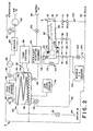
- FIGURE 2 is a diagrammatic illustration of the sterilizing apparatus and module of FIGURE 1.
- With reference to FIGURE 1, a module A for containing a medical device or other item to be sterilized is selectively interconnectable with a sterilizer apparatus B. Although the illustrated module is adapted to receive an endoscope, other shaped modules will be configured in accordance with the medical devices to be sterilized. During the sterilization process, the sterilization unit B serially supplies a sterilant solution, a sterile rinse solution, and a sterile drying gas to the module. The sterilant is held in the module and the plumbing of the unit through which the sterile rinse flows to the module for a sufficient duration to assure sterilization. During the hold or sterilization period, the unit heat sterilizes tap water or another suitable rinse solution. Optionally, other rinse water sterilization techniques may be used, such as radiation. If desired, wetting, lubricant, anticorrosion agents and the like may be mixed with the rinse water. After the sterilization process, the hermetically sealed module and the sterilized item are stored as a unit until the module is opened and the device is removed for use. This enables an inventory of sterilized items to be maintained. Because the items need not be sterilized immediately prior to use, the capacity of the sterilizer apparatus may be based on average sterile item useage of the medical facility rather than peak usage.
- With particular reference to FIGURE 2 and continuing reference to FIGURE 1, the module A is a hermetically sealed enclosure. A lid or cover 10 is opened to gain access to the interior of a
body portion 12. Interconnection means orfittings 14 enable the module to be selectively connected in a fluid exchanging relationship to the sterilizer unit B.Fluid check valves 16 are mounted in the interconnecting means to permit sterilant solution, rinse solution, and drying gas to pass into and out of the module only while it is interconnected with the sterilizer B. A fluid level control means such as astandpipe 18 assures that fluids completely fill the module and that ambient air is expelled. The module is mounted at an angle and the standpipe extends to the upper most point in the module to prevent air pockets. Concurrently with removal from the sterilizer, the check valves close preventing ambient air contamination from entering the interior of the module. This enables the module and the sterilized item or items contained therein to be removed from the sterilizer as a unit and stored in inventory. Additional modules containing other items to be sterilized may be interconnected serially with the sterilizer B. After each item is sterilized, the item and its encasing module are also inventoried. In this manner, the self-sealing module enables an inventory of sterile devices to be maintained. - The module further includes a galvanic
corrosion inhibiting means 20. In the preferred embodiment, an electrical connection means 22 electrically connects metal portions of the item to be sterilized with an exteriorelectrical connector 24. One or moreinterior electrodes 26 are connected with an exteriorelectrical connector 28. Under a suitable electrical bias applied by the sterilizer unit B, any galvanic current thresh the sterilant solution is neutralized. Optionally, other forms of cathodic protection, such as a sacrificial anode, may be provided. - The
interior electrodes 26 may be constructed of an electrically conductive material with lower electrical potential than the item. For stainless steel and brass items, satisfactory anode materials include zinc, magnesium, aluminum, or the like. - A
reservoir 30 is mounted in the sterilizer unit B such that the lowest surface of the reservoir is higher than the upper most surface of the module A. This enables fluid to flow under gravity from the reservoir and completely fill the module. Optionally, the reservoir may be mounted lower than the module and a pump provided. The reservoir includes an electrical heating means 32 for selectively heating liquids in the reservoir. A temperature sensor 34 monitors the temperature of the fluids in the reservoir. A temperature control means 36 selectively controls the electrical power through aresistive heating element 38 to maintain preselected liquid temperatures within the reservoir. - In the preferred embodiment, the temperature control means selectively heats a sterilant solution to 60°C (140°F) and boils water to 132°C (270°F). A cooling means 40 selectively reduces the temperature of the liquids in the reservoir. Specifically, a cooling
water valve 42 selectively controls the flow of tap water from a water supply manifold or means 44 through a coolingcoil 46. In a normal installation, the water manifold is connected with a sink or other water tap of the medical facility. In the preferred embodiment, tap water is sterilized by boiling at at least 132°C and cooled below 60°C before rinsing to avoid thermal degradation of the sterilized items. - The sterilant solution is formed by mixing a sterilant concentrate with tap water. A sterilant dilution or inlet
water control valve 50 and acheck valve 52 connect thewater supply 44 with thereservoir 30. Asterilant injection chamber 54 is interconnected between the sterilantdilution water valve 50 and thecheck valve 52 for selectively injecting a sterilant concentrate into received tap water. Further to the preferred embodiment, thesterilant injection chamber 54 receives a cartridge or ampule containing one or more components of a sterilant concentrate. Upon closing acover 56 to the chamber, the sterilant cartridge is punctured such that the water may flow through the sterilant cartridge and wash the sterilant concentrate therefrom. The sterilant concentrate may be either a liquid, a solid, or combination thereof. In the preferred embodiment, the sterilant concentrate cartridge includes more than one compartment for containing a hypochloride, a pH buffer, and a detergent or surfactant. - Interconnecting
tubing 60 interconnects thereservoir 30 and module receivingfluid connecting means 62. In the preferred embodiment, the module receiving connecting means includecheck valves 64 which close in the absence of a module to protect the interconnecting tubing from ambient contamination. - A tubing and module filling means or
reservoir outlet valve 70, when open, selectively releases sterilant solution and rinse solution from the -reservoir 30 to flow into and fill the interconnectingtubing 60 and the module A. When closed, thereservoir outlet valve 70 holds sterilant solution and other fluids in the interconnectingtubing 60 and the module A. Thestand pipe 18 prevents air pockets and assures that all surfaces of the interconnecting tubing, module, and item to be sterilized are held in contact with the sterilant solution for a preselected duration. - A
low level sensor 72 senses when the liquid level in the reservoir reaches substantially to the bottom of the reservoir. When the liquid level reaches the bottom of the reservoir and before the liquid level clears thereservoir outlet valve 70, thelow level sensor 72 closes thereservoir outlet valve 70 to trap and hold sterilant solution in the interconnecting tubing and module. - When the module A is mounted above the
reservoir 30, a pump is provided in the interconnectingtubing 60. Thelow level sensor 70 terminates operation of the pump sufficiently concurrently with the closing of theoutlet valve 70 so that the interconnecting tubing and the pump chambers are completely filled with sterilant solution. - An
air inlet valve 80 selectively interconnects the interior of thereservoir 30 with a source of sterile air or other drying gas. An air sterilizing means 82, such as a sterilizing filter which removes particulates which are as large or larger than bacteria, sterilizes received ambient air. Optionally, other sterilizing means may be utilized such as temperature, ozone, radiation, and the like. Aheater 84 selectively heats the air to increase its drying power. Anair pump 86 selectively supplies air under sufficient pressure to circulate the air or drying gas through thereservoir 30, the interconnectingtubing 60, and the module A. Apressure relief valve 88 selectively vents air from the reservoir as the reservoir is filled. - A high
fluid level sensor 90 senses when the fluid completely fills in thereservoir 30 and the fluid level reaches the top of the reservoir. The highfluid level sensor 90 closes the waterinlet control valve 50 when the liquid completely displaces all air from the reservoir and plumbing in fluid connection therewith. In this manner, theair inlet valve 80 is sterilized by steam as the rinse solution is heat sterilized. Apressure relief valve 92 interconnects the reservoir B with adrain 94 for permitting steam, excess water, or sterilant solution to be drained from the system. In a normal installation, thedrain 94 is interconnected with the drain of a sink or other conventional plumbing. - When filling the module A and interconnecting
tubing 60 with sterilant solution, a levelcontrol drain line 100 channels overflow sterilant solution from thestandpipe 18 to thedrain 94. At the end of the duration that sterilant solution is held in the interconnecting tubing and module, adrain valve 102 releases fluid from the module. Thedrain valve 102 selectively drains the sterilant and rinse solutions from the module through a siphonbreak 104 to thedrain 94. At the end of the rinse cycle, a moduleempty sensor 106 senses that the module has been completely drained of liquid. After the module has been completely drained, the module low level sensor enables theair pump 86 and other portions of the drying assembly. - A
printer 108 provides a printout of information concerning the sterilization process. In the preferred embodiment, the printer prints on a paper tape the date and time at which the sterilization was undertaken, the temperature of the sterilant solution as read by the temperature sensor 34 upon being introduced into the module, the duration which the sterilant was held in the module, the temperature to which the tap water was boiled and the duration of the boiling, and other system parameters. The paper tape or other appropriate print out is retained with the module and the sterlized item to provide a permanent record of the parameters of the sterilization process. - A galvanic corrosion inhibiting means 110 includes a
source 112 of a D.C. electric potential. A first electrical contact 114 interconnects the electrical potential with the first module exteriorelectric connector 24 and the item to be sterilized. A secondelectric contact 116 interconnects the electric potential with the second module exteriorelectric connector 28 and theinterior electrodes 26. Aswitch 118 connects the source of electric potential with the module while sterilant solution is therein and disconnects the potential source other times. When theelectrodes 26 are constructed of a sacrificial metal, the source of electrical potential may be omitted. - In operation, a contaminated device is closed in the module A and the module is plugged in to the sterilizer unit B. A sterilant cartridge is placed in the
sterilant injection chamber 54 and the chamber closed. The sterilizer is now ready for automatic operation. - The sterilizer B first opens the water
inlet control valve 50 which dilutes and, if applicable, dissolves components of the sterilant concentrate forming a sterilant solution. The sterilant solution passes into the reservoir B until thehigh level sensor 90 senses that the reservoir is completely filled. - The
high level sensor 90 causes the inletwater control valve 50 to close and the temperature control means 36 to heat the sterilant solution to 60°C for two to three minutes. Thereservoir outlet valve 70 opens allowing the warm sterilant solution to flow through and fill the interconnectingtubing 60 into the module A. When the module is completely filled, excess sterilant solution flows through thestandpipe 18 to thedrain 94. - When the reservoir
low level sensor 72 senses that the level of sterilant in the tank is almost to the bottom, thereservoir outlet valve 70 is caused to close. Closing thereservoir outlet valve 70 traps and holds the sterilant in the interconnecting tubing C and a module A. The sterilant solution is held in the interconnecting tubing and module for a suffient duration to sterilize the tubing, the module, and the item, in the preferred embodiment a minimum of about 10 minutes. The whole duration is calculated such that the chances of a surviving life form is no greater than one in one million, that is, a sterility assurance level of 10 -6. While the sterilant solution is in the module,switch 118 is closed causing a current flow between themodule electrode 26 and the item being sterilized to inhibit galvanic corrosion. - While the sterilant is being held in the module A and interconnecting
tubing 60, thewater inlet valve 50 is again opened to fill thereservoir 30 with additional tap water. The incoming tap water flows through the sterilant concentrate cartridge which has been fully emptied. Optionally, the same cartridge or another cartridge may include another chamber holding a rinse water treatment and the sterilizer unit B may channel the incoming tap water therethrough. The treatment may include a salt, a pH buffer, a filter, or the like. When the highliquid level sensor 90 senses that the tap water has filled the reservoir completely, the waterinlet control valve 50 is closed and the temperature control means 36 causes the water to be heated to a sterilization temperature, e.g. 132°C for at least five minutes. After the rinse water has been heat sterilized, the coolingwater valve 42 is opened to reduce the temperature of the rinse water in thereservoir 30 below 60°C to avoid heat degradation of the sterilized device. - After the sterilization period,
drain valve 102 and thereservoir outlet valve 70 are opened allowing the sterilant solution to drain from the module and allowing the rinse solution to rinse the interconnectingtubing 60, the module A, and the sterilized item with sterile rinse solution. - When the module is empty, the module
low level sensor 106 senses that the sterilant solution and the rinse solution have been drained from the module. Theair pump 86 andair heater 84 are actuated to supply a flow of hot air. Theair sterilizing filter 82 removes living organisms and other particles of comparable size such that only sterile, warm air passes through thereservoir 30, the connectingtubing 60, the module A, and out the siphonbreak 104. The warm air may be circulated through the module for a sufficient time to cause complete drying of the device. Alternately, the module may include a liquid impermeable submicron sterilization filter which allows water vapor to pass out of the module without allowing bacteria and other potential contaminants to enter. If the module has such a permeable filter port, the module may be removed from the sterilizer before complete drying. - The invention has been described with reference to the preferred embodiment. Obviously, modifications and alterations will occur to others upon reading and understanding the preceding detailed description. It is intended that the invention be construed as including all such alterations and modifications in so far as they come within the scope of the appended claims or the equivalents thereof.
Claims (10)
Priority Applications (1)
| Application Number | Priority Date | Filing Date | Title |
|---|---|---|---|
| AT87301019T ATE63222T1 (en) | 1986-02-06 | 1987-02-05 | AUTOMATED STERILIZATION DEVICE FOR LIQUIDS. |
Applications Claiming Priority (2)
| Application Number | Priority Date | Filing Date | Title |
|---|---|---|---|
| US06/826,730 US4731222A (en) | 1986-02-06 | 1986-02-06 | Automated liquid sterilization system |
| US826730 | 1986-02-06 |
Publications (3)
| Publication Number | Publication Date |
|---|---|
| EP0232170A2 true EP0232170A2 (en) | 1987-08-12 |
| EP0232170A3 EP0232170A3 (en) | 1989-06-07 |
| EP0232170B1 EP0232170B1 (en) | 1991-05-08 |
Family
ID=25247382
Family Applications (1)
| Application Number | Title | Priority Date | Filing Date |
|---|---|---|---|
| EP87301019A Expired - Lifetime EP0232170B1 (en) | 1986-02-06 | 1987-02-05 | Automated liquid sterilization system |
Country Status (8)
| Country | Link |
|---|---|
| US (2) | US4731222A (en) |
| EP (1) | EP0232170B1 (en) |
| JP (1) | JPS62186860A (en) |
| AT (1) | ATE63222T1 (en) |
| CA (1) | CA1273774A (en) |
| DE (1) | DE3769806D1 (en) |
| ES (1) | ES2021702B3 (en) |
| GR (1) | GR3001926T3 (en) |
Cited By (10)
| Publication number | Priority date | Publication date | Assignee | Title |
|---|---|---|---|---|
| EP0395296A2 (en) * | 1989-04-24 | 1990-10-31 | Steris Corporation | Microbial decontamination |
| EP0397352A2 (en) * | 1989-05-09 | 1990-11-14 | Steris Corporation | Microbial decontamination |
| EP0429960A2 (en) * | 1989-11-24 | 1991-06-05 | Sci-Can, A Division Of Lux And Zwingenberger Ltd. | Method and apparatus for steam sterilization of articles |
| US5290511A (en) * | 1989-11-24 | 1994-03-01 | Duncan Newman | Method for steam sterilization of articles |
| US5723095A (en) * | 1995-12-28 | 1998-03-03 | Steris Corporation | Cleaner concentrate formulation for biological waste fluid handling systems |
| WO1998058682A2 (en) * | 1997-06-25 | 1998-12-30 | Steris Corporation | Apparatus and method for sterilizing medical devices |
| US6448062B1 (en) | 1998-10-30 | 2002-09-10 | Metrex Research Corporation | Simultaneous cleaning and decontaminating compositions and methods |
| US6632397B1 (en) | 1998-10-01 | 2003-10-14 | Minntech Corporation | Multi-part anti-microbial concentrate system, activated solution, use-dilution solution, method of making same, and method of sterilizing with the use-dilution solution |
| US6656438B1 (en) | 1999-02-05 | 2003-12-02 | Olympus Corporation | Disinfectant solution bottle |
| EP2377458A1 (en) * | 2008-12-25 | 2011-10-19 | Olympus Medical Systems Corp. | Device for cleaning and disinfecting endoscope and method of cleaning and disinfecting endoscope |
Families Citing this family (99)
| Publication number | Priority date | Publication date | Assignee | Title |
|---|---|---|---|---|
| US5552115A (en) * | 1986-02-06 | 1996-09-03 | Steris Corporation | Microbial decontamination system with components porous to anti-microbial fluids |
| US5077008A (en) * | 1986-02-06 | 1991-12-31 | Steris Corporation | Anti-microbial composition |
| US4731222A (en) * | 1986-02-06 | 1988-03-15 | Innovative Medical Technologies | Automated liquid sterilization system |
| US5302345A (en) * | 1987-07-17 | 1994-04-12 | Oksman Henry C | Electrochemical contact lens disinfection and neutralization system |
| US5288467A (en) * | 1988-06-06 | 1994-02-22 | Hans Biermaier | Cleaning and disinfecting machine for medical equipment and instruments, anesthetic tubes, catheters, and endoscopes |
| DE69024503T2 (en) * | 1990-04-05 | 1996-05-15 | Minntech Corp | ANTI-CORROSIVE MICROBICIDES |
| DE4029088C1 (en) * | 1990-09-13 | 1992-02-13 | Fresenius Ag, 6380 Bad Homburg, De | |
| US5234124A (en) * | 1992-03-13 | 1993-08-10 | American Sterilizer Company | Cassette for sterilizing articles and latch therefor |
| WO1993017727A1 (en) * | 1992-03-13 | 1993-09-16 | American Sterilizer Company | Device and system for sterilizing objects |
| US5445792A (en) * | 1992-03-13 | 1995-08-29 | American Sterilizer Company | Optimum hydrogen peroxide vapor sterlization method |
| US5317896A (en) * | 1992-03-13 | 1994-06-07 | American Sterilizer Company | Method of detecting liquid in a sterilization system |
| JP4153029B2 (en) * | 1992-03-13 | 2008-09-17 | アメリカン ステリライザー カンパニー | Sterilization apparatus and method for a sterilant containing multiple components |
| EP0662844B1 (en) * | 1992-10-01 | 1998-03-11 | American Sterilizer Company | Accumulator-based liquid metering system and method |
| US5810620A (en) * | 1992-10-29 | 1998-09-22 | Olympus Optical Co., Ltd. | Electric connector provided with a shielding part for electrical contacts at the distal end of the plug |
| US5469841A (en) * | 1992-10-29 | 1995-11-28 | Olympus Optical Co., Ltd. | Endoscope apparatus provided with liquid removing mechanism for the electric connector |
| US5520892A (en) * | 1994-04-11 | 1996-05-28 | Bowen; John G. | Sterilization unit for dental handpieces and other instruments |
| US5882589A (en) * | 1994-06-03 | 1999-03-16 | Leon Shipper | Sealed endoscope decontamination, disinfection and drying device |
| US5529750A (en) * | 1994-09-08 | 1996-06-25 | Steris Corporation | Container with internal liquid distribution port for holding equipment with internal passages during sterilization |
| WO1997032610A1 (en) * | 1996-03-05 | 1997-09-12 | Medical Products, Inc. | Method and apparatus for disinfecting medical instruments |
| US5759486A (en) * | 1996-03-27 | 1998-06-02 | Bill F. McGraw, Trustee | Apparatus and method for sterilization of instruments |
| US5772971A (en) * | 1996-07-05 | 1998-06-30 | Symbollon Corporation | Iodine-based microbial decontamination system |
| SE507994C2 (en) * | 1996-10-14 | 1998-08-10 | Tetra Laval Holdings & Finance | Ways of sterilizing packaging material |
| US5747794A (en) * | 1996-10-16 | 1998-05-05 | Steris Corporation | Scanning device for evaluating cleanliness and integrity of medical and dental instruments |
| US5863498A (en) * | 1997-02-07 | 1999-01-26 | Steris Corporation | Decontamination apparatus door unit |
| DE19721538A1 (en) | 1997-05-22 | 1998-11-26 | Hans Biermaier | Device for cleaning, sterilizing, transporting and storing medical devices, in particular endoscopes |
| US6203756B1 (en) | 1997-12-17 | 2001-03-20 | Johnson & Johnson Medical, Inc. | Integrated cleaning sterilization process |
| US20050163655A1 (en) * | 1997-06-11 | 2005-07-28 | Szu-Min Lin | Integrated washing and sterilization process |
| US7556767B2 (en) * | 1997-12-17 | 2009-07-07 | Ethicon, Inc. | Integrated washing and sterilization process |
| DE19731965A1 (en) * | 1997-07-24 | 1999-01-28 | Etm Endotech Gmbh Medizintechn | Air / water and suction valves on endoscopes |
| US5932171A (en) * | 1997-08-13 | 1999-08-03 | Steris Corporation | Sterilization apparatus utilizing catholyte and anolyte solutions produced by electrolysis of water |
| US7229591B2 (en) * | 1997-08-21 | 2007-06-12 | Ethicon, Inc. | Lumen sterilization device and method |
| AU735234B2 (en) * | 1997-12-04 | 2001-07-05 | Steris Corporation | Chemical modification of electrochemically activated water |
| US6645430B1 (en) | 1997-12-17 | 2003-11-11 | Ethicon, Inc. | Method and apparatus for processing device with fluid submersion |
| US6685895B1 (en) | 1997-12-17 | 2004-02-03 | Ethicon, Inc. | Method and apparatus for processing device with reduced occlusion |
| US6083458A (en) * | 1997-12-17 | 2000-07-04 | Ethicon, Inc. | Apparatus and method for providing fluid to devices with reduced or without occlusion |
| US6187266B1 (en) | 1997-12-17 | 2001-02-13 | Johnson & Johnson Medical, Inc. | Integrated cleaning/sterilization process with lumen devices |
| US6013227A (en) * | 1997-12-17 | 2000-01-11 | Johnson & Johnson Medical, Inc. | Lumen device reprocessor without occlusion |
| US6596232B1 (en) | 1997-12-17 | 2003-07-22 | Ethicon, Inc. | Device processing apparatus and method having positive pressure with two partitions to minimize leakage |
| US6015529A (en) * | 1997-12-17 | 2000-01-18 | Johnson & Johnson Medical, Inc. | Tray/container system for cleaning/sterilization processes |
| US6103189A (en) * | 1998-03-10 | 2000-08-15 | Kralovic; Raymond C. | Method of removing microbial contamination |
| AU755635B2 (en) | 1998-10-01 | 2002-12-19 | Minntech Corporation | Endoscope reprocessing and sterilization system |
| US6203767B1 (en) * | 1998-11-06 | 2001-03-20 | Steris Corporation | Peracetic acid card reader and card style sensor |
| AU1827600A (en) | 1998-11-23 | 2000-06-13 | Ecolab Inc. | Non-corrosive sterilant composition |
| DE69938259T2 (en) | 1998-12-30 | 2009-02-26 | Ethicon Inc. | STERILE PACKAGING FOR FLEXIBLE ENDOSCOPES |
| US6534002B1 (en) | 1998-12-30 | 2003-03-18 | Ethicon, Inc. | Flow of fluid through a lumen device from smaller-caliber end to larger-caliber end |
| US6312645B1 (en) | 1998-12-30 | 2001-11-06 | Ethicon, Inc. | Container with collapsible pouch for cleaning or sterilization |
| DE60020419T2 (en) * | 1999-02-05 | 2006-05-04 | Olympus Corporation, Shibuya | Device for cleaning and disinfecting endoscopes |
| US6352837B1 (en) | 1999-02-22 | 2002-03-05 | 3M Innovative Properties Company | Rapid readout sterilization indicator for liquid peracetic acid sterilization procedures |
| AUPQ036599A0 (en) | 1999-05-14 | 1999-06-10 | Fairmont Medical Products Pty Ltd | Sterilisation method and container therefor |
| US6749807B1 (en) * | 1999-05-19 | 2004-06-15 | Steris Corporation | Flow through chemical indicator for measurement of active biocidal agents in a single use package |
| AUPQ125999A0 (en) * | 1999-06-28 | 1999-07-22 | Securency Pty Ltd | Method of producing a diffractive structure in security documents |
| US6527872B1 (en) | 1999-07-28 | 2003-03-04 | Steris Inc. | Environmentally friendly peracetic acid decontamination formula with increased performance and chemical stability |
| US6485979B1 (en) | 1999-08-05 | 2002-11-26 | 3M Innovative Properties Company | Electronic system for tracking and monitoring articles to be sterilized and associated method |
| US6790411B1 (en) * | 1999-12-02 | 2004-09-14 | 3M Innovative Properties Company | Hydrogen peroxide indicator and method |
| US6279622B1 (en) | 2000-02-07 | 2001-08-28 | Ethicon, Inc. | Method and system for delivering and metering liquid sterilant |
| US6656423B1 (en) * | 2000-02-07 | 2003-12-02 | Steris Inc. | Sterile water generator |
| US6585943B1 (en) | 2000-02-07 | 2003-07-01 | Steris Inc. | Liquid cleaning and sterilization system |
| US6482358B1 (en) | 2000-02-07 | 2002-11-19 | Steris Inc. | Three part cup for packaging cleaning and sterilizing agents and sequential cutter |
| US6558620B1 (en) | 2000-02-07 | 2003-05-06 | Steris Inc. | Liquid cleaning and sterilization method |
| US6582654B1 (en) | 2000-02-07 | 2003-06-24 | Steris Inc. | Fluid spray system for cleaning and sterilizing medical devices supported on a rack |
| US6814932B2 (en) * | 2000-03-31 | 2004-11-09 | Steris Inc. | Device support activation system |
| US6982169B2 (en) * | 2001-01-15 | 2006-01-03 | Morphotek, Inc. | Chemical inhibitors of mismatch repair |
| US6499495B2 (en) | 2001-01-24 | 2002-12-31 | Allegiance Corporation | Waste treatment system for suction canisters |
| JP5035493B2 (en) * | 2001-03-28 | 2012-09-26 | 栗田工業株式会社 | Water treatment equipment provision system |
| US7803315B2 (en) * | 2001-10-05 | 2010-09-28 | American Sterilizer Company | Decontamination of surfaces contaminated with prion-infected material with gaseous oxidizing agents |
| US7192554B2 (en) * | 2001-12-31 | 2007-03-20 | 3M Innovative Properties Company | Hydrogen peroxide and peracetic acid indicators and methods |
| US7351386B2 (en) | 2002-04-04 | 2008-04-01 | Steris Inc | Cartridge holder for automated reprocessor |
| US6919057B2 (en) * | 2002-04-04 | 2005-07-19 | Steris Inc. | Automated endoscope reprocessor |
| US7314966B2 (en) * | 2003-08-01 | 2008-01-01 | Steris Inc. | Method for deactivating and maintaining items in a deactivated state |
| US7476368B2 (en) * | 2003-08-01 | 2009-01-13 | American Sterilizer Company | Method and device for deactivating items and for maintaining such items in a deactivated state |
| US7169369B2 (en) * | 2003-08-01 | 2007-01-30 | Steris Inc. | Method and device for deactivating items and for maintaining such items in a deactivated state |
| US7569182B2 (en) * | 2003-08-01 | 2009-08-04 | American Sterilizer Company | Filter assembly for a reprocessor |
| US6979428B2 (en) * | 2003-08-01 | 2005-12-27 | Steris Inc. | Fluid over-flow/make-up air assembly for reprocessor |
| AU2005222069B2 (en) | 2004-03-05 | 2010-09-09 | Gen-Probe Incorporated | Reagents, methods and kits for use in deactivating nucleic acids |
| US20050220665A1 (en) * | 2004-04-05 | 2005-10-06 | Ding Lambert L | Low temperature sterilization and disinfections method and apparatus for medical apparatus and instruments |
| US20050226795A1 (en) * | 2004-04-05 | 2005-10-13 | Steriquip, Inc. | Durable fill block for flow of fluids through a hinged lid |
| US20070098591A1 (en) * | 2005-10-31 | 2007-05-03 | Georg Frinke | Method and apparatus for low energy vaporization of liquid oxidizing agents or solutions |
| WO2008020895A2 (en) | 2006-03-06 | 2008-02-21 | American Sterilizer Company | Apparatus for deactivating instruments and devices |
| US8252246B2 (en) * | 2007-04-30 | 2012-08-28 | Midmark Corporation | Water management system for sterilizer |
| JP2009022513A (en) * | 2007-07-19 | 2009-02-05 | Fujifilm Corp | Method of rinsing endoscope |
| WO2010048028A2 (en) * | 2008-10-23 | 2010-04-29 | Johnsondiversey, Inc. | Apparatus for preparing a sterile composition |
| US20110217204A1 (en) * | 2010-03-05 | 2011-09-08 | Franciskovich Phillip P | Sterilization composition |
| US8753580B2 (en) | 2010-07-20 | 2014-06-17 | Pci Medical, Inc. | Intracavity ultrasound probe disinfectant system |
| WO2013003110A1 (en) * | 2011-06-29 | 2013-01-03 | General Electric Company | Molybdate-free sterilizing and pasteurizing solutions |
| US10022189B2 (en) | 2013-12-16 | 2018-07-17 | Stryker Sustainability Solutions, Inc. | Apparatus and method for cleaning an instrument |
| US10463754B2 (en) | 2014-04-28 | 2019-11-05 | American Sterilizer Company | Process for decontaminating or sterilizing an article |
| US10750749B2 (en) | 2014-04-28 | 2020-08-25 | American Sterilizer Company | Process and composition for killing spores |
| US10869479B2 (en) | 2014-04-28 | 2020-12-22 | American Sterilizer Company | Wipe for killing spores |
| DE102014019774A1 (en) | 2014-06-10 | 2016-05-04 | Innovations-Transfer Uphoff Gmbh & Co. Kg | Method and device for cleaning, disinfecting and sterilizing objects |
| DE102014008171B4 (en) | 2014-06-10 | 2023-02-09 | Innovations-Transfer Uphoff Gmbh & Co. Kg | Method and device for cleaning, disinfecting and sterilizing objects |
| US10330209B2 (en) | 2017-01-26 | 2019-06-25 | Fresenius Medical Care Holdings, Inc. | Check valve and method of forming a check valve |
| CN110740949B (en) * | 2017-06-21 | 2023-11-03 | 雀巢产品有限公司 | Liquid dispensing apparatus |
| CN107399442A (en) * | 2017-07-31 | 2017-11-28 | 芜湖杨燕制药有限公司 | A kind of dosing technology of traditional Chinese medicine |
| WO2020061122A1 (en) * | 2018-09-17 | 2020-03-26 | Ped Technologies Holdings, Llc | Dry fog production and application methods and systems |
| CN109328535A (en) * | 2018-12-07 | 2019-02-15 | 贵州大学 | A kind of tiny Seed sterilization device |
| CN112317443B (en) * | 2020-10-15 | 2022-02-08 | 山东中医药大学附属医院 | Traditional chinese medical science internal medicine is filter equipment for medical instrument |
| CN113247843A (en) * | 2021-06-02 | 2021-08-13 | 安徽医科大学第一附属医院 | Collector is opened to ampoule |
| CN115228834B (en) * | 2022-08-15 | 2023-07-07 | 泰州永兴合金材料科技有限公司 | Alloy processing waste material collection processing apparatus |
| CN115814114A (en) * | 2023-02-13 | 2023-03-21 | 潍坊医学院附属医院 | Quick degassing unit of medical instrument |
Citations (5)
| Publication number | Priority date | Publication date | Assignee | Title |
|---|---|---|---|---|
| US3893832A (en) * | 1973-11-01 | 1975-07-08 | Mead Corp | Sterile fluid system |
| DE2749448A1 (en) * | 1977-11-04 | 1979-05-10 | Stierlen Maquet Ag | Cleaning combined with disinfection - in four chambers with disinfectant added to cleansing agent |
| EP0098419A1 (en) * | 1982-07-05 | 1984-01-18 | Bode Chemie GmbH & Co. | Equipment for the addition of a disinfectant to water |
| DE3339930A1 (en) * | 1983-11-04 | 1985-05-23 | Hamba-Maschinenfabrik Hans A.Müller GmbH & Co KG, 5600 Wuppertal | Method and device for sterilization of cup-shaped containers intended for accommodation of dairy products |
| US4552728A (en) * | 1981-05-11 | 1985-11-12 | Hal Johnston Pty. Limited | Decontamination apparatus |
Family Cites Families (16)
| Publication number | Priority date | Publication date | Assignee | Title |
|---|---|---|---|---|
| DE8419C (en) * | TH. DUPUY & FILS in Paris | Lithographic rubbing press | ||
| US3478758A (en) * | 1967-02-13 | 1969-11-18 | George W Davies | Washing and sterilizing device |
| US3511706A (en) * | 1967-05-11 | 1970-05-12 | Donald J Orr | Method of cleaning and sanitizing food processing devices |
| US3739791A (en) * | 1970-06-24 | 1973-06-19 | Arbrook Inc | Decontamination apparatus |
| US4116782A (en) * | 1977-03-07 | 1978-09-26 | The Dow Chemical Company | Corrosion prevention system |
| US4261950A (en) * | 1979-02-06 | 1981-04-14 | American Sterilizer Company | Sterilizing apparatus and integrated sterilizer control |
| DE2938400A1 (en) * | 1979-09-22 | 1981-04-02 | Richard Wolf Gmbh, 7134 Knittlingen | Automatic sterilisation of tubing - having supply of disinfectant which is pulsed into tubing followed by flush of sterile water |
| US4396582A (en) * | 1980-03-31 | 1983-08-02 | Dai Nippon Insatsu Kabushiki Kaisha | Method and apparatus for sterilizing food packages or the like |
| JPS56161922A (en) * | 1980-05-07 | 1981-12-12 | Dainippon Printing Co Ltd | Method of sterilizing packing material |
| US4623516A (en) * | 1981-01-05 | 1986-11-18 | Automatic Liquid Packaging, Inc. | Sterilizing method for an encapsulating machine |
| US4337223A (en) * | 1981-02-13 | 1982-06-29 | Ben Venue Laboratories, Inc. | Sterilizing apparatus incorporating recirculation of chamber atmosphere |
| US4526623A (en) * | 1983-04-15 | 1985-07-02 | Olympus Optical Co., Ltd. | Method of cleaning endoscope channels |
| US4576650A (en) * | 1983-04-22 | 1986-03-18 | Olympus Optical Co., Ltd. | Method of cleaning endoscope channels |
| DE3417571C2 (en) * | 1983-05-16 | 1986-10-30 | Olympus Optical Co., Ltd., Tokio/Tokyo | Process for cleaning endoscopes and endoscopes therefor |
| US4617065A (en) * | 1984-12-20 | 1986-10-14 | American Sterilizer Company | Method for liquid disinfecting and sterile rinsing |
| US4731222A (en) * | 1986-02-06 | 1988-03-15 | Innovative Medical Technologies | Automated liquid sterilization system |
-
1986
- 1986-02-06 US US06/826,730 patent/US4731222A/en not_active Expired - Lifetime
-
1987
- 1987-02-02 CA CA000528775A patent/CA1273774A/en not_active Expired - Lifetime
- 1987-02-05 EP EP87301019A patent/EP0232170B1/en not_active Expired - Lifetime
- 1987-02-05 ES ES87301019T patent/ES2021702B3/en not_active Expired - Lifetime
- 1987-02-05 DE DE8787301019T patent/DE3769806D1/en not_active Expired - Lifetime
- 1987-02-05 AT AT87301019T patent/ATE63222T1/en not_active IP Right Cessation
- 1987-02-06 JP JP62026190A patent/JPS62186860A/en active Granted
-
1988
- 1988-01-04 US US07/140,388 patent/US4892706A/en not_active Expired - Lifetime
-
1991
- 1991-05-09 GR GR91400578T patent/GR3001926T3/en unknown
Patent Citations (5)
| Publication number | Priority date | Publication date | Assignee | Title |
|---|---|---|---|---|
| US3893832A (en) * | 1973-11-01 | 1975-07-08 | Mead Corp | Sterile fluid system |
| DE2749448A1 (en) * | 1977-11-04 | 1979-05-10 | Stierlen Maquet Ag | Cleaning combined with disinfection - in four chambers with disinfectant added to cleansing agent |
| US4552728A (en) * | 1981-05-11 | 1985-11-12 | Hal Johnston Pty. Limited | Decontamination apparatus |
| EP0098419A1 (en) * | 1982-07-05 | 1984-01-18 | Bode Chemie GmbH & Co. | Equipment for the addition of a disinfectant to water |
| DE3339930A1 (en) * | 1983-11-04 | 1985-05-23 | Hamba-Maschinenfabrik Hans A.Müller GmbH & Co KG, 5600 Wuppertal | Method and device for sterilization of cup-shaped containers intended for accommodation of dairy products |
Cited By (18)
| Publication number | Priority date | Publication date | Assignee | Title |
|---|---|---|---|---|
| US5116575A (en) * | 1986-02-06 | 1992-05-26 | Steris Corporation | Powdered anti-microbial composition |
| EP0395296A2 (en) * | 1989-04-24 | 1990-10-31 | Steris Corporation | Microbial decontamination |
| EP0395296A3 (en) * | 1989-04-24 | 1991-09-11 | Steris Corporation | Microbial decontamination |
| EP0397352A2 (en) * | 1989-05-09 | 1990-11-14 | Steris Corporation | Microbial decontamination |
| EP0397352A3 (en) * | 1989-05-09 | 1991-09-11 | Steris Corporation | Microbial decontamination |
| US5571476A (en) * | 1989-11-24 | 1996-11-05 | Newman; Duncan | Pressure chamber for steam sterilization of articles |
| US5290511A (en) * | 1989-11-24 | 1994-03-01 | Duncan Newman | Method for steam sterilization of articles |
| EP0429960B1 (en) * | 1989-11-24 | 1995-05-31 | Sci-Can, A Division Of Lux And Zwingenberger Ltd. | Method and apparatus for steam sterilization of articles |
| EP0429960A2 (en) * | 1989-11-24 | 1991-06-05 | Sci-Can, A Division Of Lux And Zwingenberger Ltd. | Method and apparatus for steam sterilization of articles |
| US5723095A (en) * | 1995-12-28 | 1998-03-03 | Steris Corporation | Cleaner concentrate formulation for biological waste fluid handling systems |
| WO1998058682A2 (en) * | 1997-06-25 | 1998-12-30 | Steris Corporation | Apparatus and method for sterilizing medical devices |
| WO1998058682A3 (en) * | 1997-06-25 | 1999-05-14 | Steris Corp | Apparatus and method for sterilizing medical devices |
| US6632397B1 (en) | 1998-10-01 | 2003-10-14 | Minntech Corporation | Multi-part anti-microbial concentrate system, activated solution, use-dilution solution, method of making same, and method of sterilizing with the use-dilution solution |
| US6448062B1 (en) | 1998-10-30 | 2002-09-10 | Metrex Research Corporation | Simultaneous cleaning and decontaminating compositions and methods |
| US6656438B1 (en) | 1999-02-05 | 2003-12-02 | Olympus Corporation | Disinfectant solution bottle |
| EP2377458A1 (en) * | 2008-12-25 | 2011-10-19 | Olympus Medical Systems Corp. | Device for cleaning and disinfecting endoscope and method of cleaning and disinfecting endoscope |
| EP2377458A4 (en) * | 2008-12-25 | 2013-01-16 | Olympus Medical Systems Corp | Device for cleaning and disinfecting endoscope and method of cleaning and disinfecting endoscope |
| US8715425B2 (en) | 2008-12-25 | 2014-05-06 | Olympus Medical Systems Corp. | Endoscope cleaning/disinfecting apparatus and endoscope cleaning/disinfecting method |
Also Published As
| Publication number | Publication date |
|---|---|
| ATE63222T1 (en) | 1991-05-15 |
| EP0232170A3 (en) | 1989-06-07 |
| JPH0430865B2 (en) | 1992-05-22 |
| EP0232170B1 (en) | 1991-05-08 |
| US4731222A (en) | 1988-03-15 |
| US4892706A (en) | 1990-01-09 |
| CA1273774A (en) | 1990-09-11 |
| JPS62186860A (en) | 1987-08-15 |
| DE3769806D1 (en) | 1991-06-13 |
| GR3001926T3 (en) | 1992-11-23 |
| ES2021702B3 (en) | 1991-11-16 |
Similar Documents
| Publication | Publication Date | Title |
|---|---|---|
| EP0232170B1 (en) | Automated liquid sterilization system | |
| US5552115A (en) | Microbial decontamination system with components porous to anti-microbial fluids | |
| US5091343A (en) | Container for holding equipment during sterilization | |
| US5217698A (en) | Office size instrument sterilization system | |
| EP1492573B1 (en) | Automated endoscope reprocessor | |
| KR900004315B1 (en) | Combination steam and unsaturated chemical vapor sterilizer | |
| EP1567066B1 (en) | Apparatus and method for steam reprocessing flexible endoscopes | |
| US6656423B1 (en) | Sterile water generator | |
| ES2247528T3 (en) | CARTRIDGE SUPPORT FOR DECONTAMINATION SYSTEMS. | |
| EP0779822B1 (en) | Container with internal liquid distribution port for holding equipment with internal passages during sterilization | |
| MXPA97001643A (en) | Container with internal door distributing liquid, to retain a team with internal passages, during the sterilization | |
| CA2012862C (en) | Container for holding equipment during sterilization |
Legal Events
| Date | Code | Title | Description |
|---|---|---|---|
| PUAI | Public reference made under article 153(3) epc to a published international application that has entered the european phase |
Free format text: ORIGINAL CODE: 0009012 |
|
| AK | Designated contracting states |
Kind code of ref document: A2 Designated state(s): AT BE CH DE ES FR GB GR IT LI LU NL SE |
|
| PUAL | Search report despatched |
Free format text: ORIGINAL CODE: 0009013 |
|
| AK | Designated contracting states |
Kind code of ref document: A3 Designated state(s): AT BE CH DE ES FR GB GR IT LI LU NL SE |
|
| 17P | Request for examination filed |
Effective date: 19890807 |
|
| RAP1 | Party data changed (applicant data changed or rights of an application transferred) |
Owner name: STERIS CORPORATION |
|
| 17Q | First examination report despatched |
Effective date: 19891211 |
|
| GRAA | (expected) grant |
Free format text: ORIGINAL CODE: 0009210 |
|
| AK | Designated contracting states |
Kind code of ref document: B1 Designated state(s): AT BE CH DE ES FR GB GR IT LI LU NL SE |
|
| REF | Corresponds to: |
Ref document number: 63222 Country of ref document: AT Date of ref document: 19910515 Kind code of ref document: T |
|
| ITF | It: translation for a ep patent filed |
Owner name: ING. C. GREGORJ S.P.A. |
|
| REF | Corresponds to: |
Ref document number: 3769806 Country of ref document: DE Date of ref document: 19910613 |
|
| ET | Fr: translation filed | ||
| PLBE | No opposition filed within time limit |
Free format text: ORIGINAL CODE: 0009261 |
|
| STAA | Information on the status of an ep patent application or granted ep patent |
Free format text: STATUS: NO OPPOSITION FILED WITHIN TIME LIMIT |
|
| 26N | No opposition filed | ||
| REG | Reference to a national code |
Ref country code: GR Ref legal event code: FG4A Free format text: 3001926 |
|
| EPTA | Lu: last paid annual fee | ||
| EAL | Se: european patent in force in sweden |
Ref document number: 87301019.3 |
|
| REG | Reference to a national code |
Ref country code: GB Ref legal event code: IF02 |
|
| PGFP | Annual fee paid to national office [announced via postgrant information from national office to epo] |
Ref country code: NL Payment date: 20060216 Year of fee payment: 20 |
|
| PGFP | Annual fee paid to national office [announced via postgrant information from national office to epo] |
Ref country code: FR Payment date: 20060217 Year of fee payment: 20 |
|
| PGFP | Annual fee paid to national office [announced via postgrant information from national office to epo] |
Ref country code: AT Payment date: 20060221 Year of fee payment: 20 |
|
| PGFP | Annual fee paid to national office [announced via postgrant information from national office to epo] |
Ref country code: GB Payment date: 20060223 Year of fee payment: 20 |
|
| PGFP | Annual fee paid to national office [announced via postgrant information from national office to epo] |
Ref country code: ES Payment date: 20060224 Year of fee payment: 20 |
|
| PGFP | Annual fee paid to national office [announced via postgrant information from national office to epo] |
Ref country code: CH Payment date: 20060227 Year of fee payment: 20 |
|
| PGFP | Annual fee paid to national office [announced via postgrant information from national office to epo] |
Ref country code: IT Payment date: 20060228 Year of fee payment: 20 Ref country code: GR Payment date: 20060228 Year of fee payment: 20 |
|
| PGFP | Annual fee paid to national office [announced via postgrant information from national office to epo] |
Ref country code: LU Payment date: 20060310 Year of fee payment: 20 |
|
| PGFP | Annual fee paid to national office [announced via postgrant information from national office to epo] |
Ref country code: BE Payment date: 20060316 Year of fee payment: 20 |
|
| PGFP | Annual fee paid to national office [announced via postgrant information from national office to epo] |
Ref country code: DE Payment date: 20060331 Year of fee payment: 20 |
|
| PG25 | Lapsed in a contracting state [announced via postgrant information from national office to epo] |
Ref country code: GB Free format text: LAPSE BECAUSE OF EXPIRATION OF PROTECTION Effective date: 20070204 |
|
| PG25 | Lapsed in a contracting state [announced via postgrant information from national office to epo] |
Ref country code: NL Free format text: LAPSE BECAUSE OF EXPIRATION OF PROTECTION Effective date: 20070205 |
|
| PG25 | Lapsed in a contracting state [announced via postgrant information from national office to epo] |
Ref country code: ES Free format text: LAPSE BECAUSE OF EXPIRATION OF PROTECTION Effective date: 20070206 |
|
| REG | Reference to a national code |
Ref country code: GB Ref legal event code: PE20 Ref country code: CH Ref legal event code: PL |
|
| NLV7 | Nl: ceased due to reaching the maximum lifetime of a patent |
Effective date: 20070205 |
|
| EUG | Se: european patent has lapsed | ||
| REG | Reference to a national code |
Ref country code: ES Ref legal event code: FD2A Effective date: 20070206 |
|
| BE20 | Be: patent expired |
Owner name: *STERIS CORP. Effective date: 20070205 |
|
| PGFP | Annual fee paid to national office [announced via postgrant information from national office to epo] |
Ref country code: SE Payment date: 20060227 Year of fee payment: 20 |