EP0240593A1 - Improved transdermal drug applicator and electrodes therefor - Google Patents
Improved transdermal drug applicator and electrodes therefor Download PDFInfo
- Publication number
- EP0240593A1 EP0240593A1 EP86110164A EP86110164A EP0240593A1 EP 0240593 A1 EP0240593 A1 EP 0240593A1 EP 86110164 A EP86110164 A EP 86110164A EP 86110164 A EP86110164 A EP 86110164A EP 0240593 A1 EP0240593 A1 EP 0240593A1
- Authority
- EP
- European Patent Office
- Prior art keywords
- transdermal drug
- applicator according
- drug applicator
- skin
- applicator
- Prior art date
- Legal status (The legal status is an assumption and is not a legal conclusion. Google has not performed a legal analysis and makes no representation as to the accuracy of the status listed.)
- Granted
Links
Images


Classifications
-
- A—HUMAN NECESSITIES
- A61—MEDICAL OR VETERINARY SCIENCE; HYGIENE
- A61N—ELECTROTHERAPY; MAGNETOTHERAPY; RADIATION THERAPY; ULTRASOUND THERAPY
- A61N1/00—Electrotherapy; Circuits therefor
- A61N1/18—Applying electric currents by contact electrodes
- A61N1/20—Applying electric currents by contact electrodes continuous direct currents
- A61N1/30—Apparatus for iontophoresis, i.e. transfer of media in ionic state by an electromotoric force into the body, or cataphoresis
-
- A—HUMAN NECESSITIES
- A61—MEDICAL OR VETERINARY SCIENCE; HYGIENE
- A61N—ELECTROTHERAPY; MAGNETOTHERAPY; RADIATION THERAPY; ULTRASOUND THERAPY
- A61N1/00—Electrotherapy; Circuits therefor
- A61N1/02—Details
- A61N1/04—Electrodes
- A61N1/0404—Electrodes for external use
- A61N1/0408—Use-related aspects
- A61N1/0428—Specially adapted for iontophoresis, e.g. AC, DC or including drug reservoirs
- A61N1/0432—Anode and cathode
- A61N1/044—Shape of the electrode
-
- A—HUMAN NECESSITIES
- A61—MEDICAL OR VETERINARY SCIENCE; HYGIENE
- A61N—ELECTROTHERAPY; MAGNETOTHERAPY; RADIATION THERAPY; ULTRASOUND THERAPY
- A61N1/00—Electrotherapy; Circuits therefor
- A61N1/02—Details
- A61N1/04—Electrodes
- A61N1/0404—Electrodes for external use
- A61N1/0408—Use-related aspects
- A61N1/0428—Specially adapted for iontophoresis, e.g. AC, DC or including drug reservoirs
- A61N1/0448—Drug reservoir
Definitions
- This invention relates to transdermal drug applicators, as well as to electrode constructions for use with such applicators; and more particularly to drug applicators which are electrically operated and exhibit a mass transfer phenomena which facilitates the transcutaneous delivery or transfer of drugs, medicaments, and the like.
- Transdermal drug applicators embody various electrode constructions. However, since the overall size of the applicator should be minimized for cost effectiveness and aesthetics and the dosage capability desirably maximized, it is an object of the present invention to provide improved applicators as well as improved electrode constructions which are applicable to both the active and inactive electrodes. In addition, it is another object of the invention to provide drug applicators which employ only active electrodes, or with different drugs in each electrode structure, or with the active and inactive electrodes of different sizes. Moreover, the invention further pertains to drug applicators incorporating three electrodes which may operate to deliver drugs independently of each other using separate mass transfer phenomenas, such as electrophoresis and electroosmosis or endosmose.
- applicator 10 consists of an outer cover 12 having a raise portion 14 and a lip 16 along the outer periphery. It is understood that applicator 10 can have any convenient shape or size, for example, square, rectangul oval,circular,or tailored for a specific location on the skin, as long as this is a raised central portion to accommodate the rest of the electrophoresis unit to be described and the lip along its periphery.
- the first layer is a microporous or semi-permeable membrane 22 through which the medicament migrates to be deposited on skin 18.
- membrane 22 may not be needed depending on the nature of the reservoir for the medicament.
- the second layer consists of a flexible pouch or reservoir 24 containing the drug to be administered.
- reservoir 24 can be a pouch containing the drug of choice in solution or suspension, the walls of which are sufficiently dense to prevent leakage of the drug under ambient conditions, but sufficiently porous to permit migration of the charged particles or ions under the influence of the electric field imposed.
- the microporous membrane 22 when leakage under ambient conditions could occur, for example, as a result of packing of the applicators for shipment or storage, fluctuating temperatures, and possibly puncture of the reservoir.
- the use of the membrane 22 could depend in large measure on the nature of the medicament involved.
- reservoir 24 can consist of porous material in which the drug is impregnated rather than a pouch containing the liquid medicament.
- the third or next layer above reservoir 24 is an extended contact 26 which could be incorporated as one face of battery 28 which is the next layer.
- Contact 26 could be any suitable conductive material, preferably conformable to permit applicator 10 to be curved or bent to conform to the shaped surface of the skin. Suitable materials of this type are well known in the art and include electrically conductive polymers, preferably non-ionic. Carbon loaded or surface metalized plastics are also available for such use.
- Battery 28 comprising the next layer can be made up of a group of cells internally connected in series to obtain the desired voltage necessary to obtain the electrophoretic action with the particular medicament. Orientation of battery 28 would depend on whether the charged (ionic) particles of the drug of choice are positive or negative. If the particles are negatively charged in solution or suspension then contact 26 would be connected to the negative side of battery 28 as the skin will then be positive with respect to that contact and will attract the ions. With regard to battery 28, it should be noted that any conventional miniaturized battery cells now generally available can be employed, arranged and connected in series to obtain the desired operating voltage. In addition, the technology now exists for batteries which are made up of very thin, flexible sheets of a conductive polymer with high surface areas relative to thickness to provide adequate current densities.
- plastic battery is described in "Batteries Today", Autumn 1981, pages 10, 11, and 24.
- sheets may be layered to place the cells in series, and an effective compromise between number of sheets and surface areas of sheets is to layer them in a diagonal as shown somewhat schematically in Fig. 2.
- battery selection would ultimately depend on such voltage and current densities required for a specific application, and time of discharge.
- Cover 12 which encloses all of the layers of applicator 10 is made from a flexible conductive plastic material such as a polymer impregnated with carbon or surface metalized plastic. Insulating material 34 fills the space between the side wall of raised portion 14 and the various layers contained therein.
- An electrically conductive adhesive material 36 coats the underside of lip 16 so that applicator 10 may be placed on and adhere to skin 18 and make good electrical contact.
- Battery 28 is connected through contact 32, cover 12, and adhesive layer 36 to skin 18.
- the other side of battery 28 is connected electrically through contact 26, liquid reservoir 24 and membrane 22 to skin 18 to complete the circuit.
- Resistor Reff represents the effective resistance of the complete circuit, including skin 18, the adhesive layer 36, cover 12, battery 28 and its contacts 26 and 32, as well as reservoir 24 and membrane 22,
- one of the aims is to establish a very low rate of current flow so that the medicament will be deposited slowly over a long period of time.
- Current flow of down as low as 0.0001 ampere-hour per square centimeter of skin surface below membrane 22 is a typical current which may be selected for the application of a particular drug.
- applicator 10 may be designed to incorporate provision to insure that the deposit of medicament will cease after a given period of time or after a certain quantity of drug is administered.
- This can be accomplished by inserting in the circuit an integrating device such as a reverse plating cell 38.
- Cell 38 as is known in the art, comprises a pair of electrodes on which one is a coating of material to be transferred to the other electrode. When all of the plating material is deposited, after a predetermined period of time based upon the thickness of the original coating has lapsed, or integrated current flow representing the desired quantity of drug to be delivered, there is a large increase in internal resistance resulting in a substantial drop of current flow and an effective halt to drug migration.
- Cell 38 is a relatively high resistance device and could provide for much of the high resistance required for the operation of applicator 10.
- Cell 38 may be made a part of contact 32 or be inserted between contact 32 and cover material 14. In addition, provision may be made for current flow to be built up gradually to avoid any shock to the recipient of the drug.
- Applicator 10 may be prepared in advance, in different sizes and shapes, sealed within a plastic pouch, with a protective strip over its exposed side. Different drugs can be incorporated for particular applications, batteries may be varied to meet specific current flow requirements, and of course the electrical orientation of each battery would depend on the particular medicament. In the use of the device, the protective strip is removed and the applicator placed on the skin where desired and current flow starts immediately along with migration of the drug.
- At least two drugs can be transdermally transported simultaneously, across the skin, using one or more transfer modalities.
- Such an arrangement may be particularly effective in situations where two or more drugs work better together than if taken spearately.
- aspirin and codei exhibit a synergistic or improved effect when used together, rather than independently of each other.
- Other well known drug combinations, such as Dristan exhibit similar results.
- drug delivery can be varied and may be effected by one or more mass transfer phenomena such as electroosmosis and iontophoresis and electrophoresis.
- element 10 ⁇ represents the active electrode and it is spaced apart or separated from the inactive electrode by a suitable gap or space, including an air gap.
- the gap is suitably illustrated as a "dam" 208 which may be made of an inpervious, non-conductive material, such as silicone. This dam 208 maintains electrode separation and provide a seal against the skin so as to preclude any "shorting"effect across the electrodes which might occur due to sweat and other moisture accumulated on the surface of the skin beneath or adjacent t such dam or electrode barrier means.
- Element 12 ⁇ is a cover material similar to the outer cover 12 of Figures 1-2, although it need not be electrically conductive, since the power source or battery 28 ⁇ and series connected constant current device 212 (which may suitably comprise a diode) is suitably connected by wire leads or conductors to the separate conductive terminals or film elements 204 and 205 ⁇ .
- Preferred elements may be made of a carbonized plastic, foil or other conductive film, such as a metalized mylar.
- Membrane 22 ⁇ is optional as is element 22 of Figures 1-4 and comprises a semi-permeable, microporous membrane element having an adhesive and preferably gel-like quality.
- Element 34 ⁇ is a suitable impermeable, insulating material which is preferably formed so as to protrude beyond element 22 ⁇ and thus form an effective dam-like seal between the separated electrodes forming the applicator patent.
- element 34 ⁇ should be impervious to not only the drugs, water, etc., but it should also be non-conducting.
- the "indifferent" electrode 210 which may also comprise a drug matrix or reservoir is disposed between microporous membrane 22 ⁇ and the conductive element 204 ⁇ .
- suitable drug matrix or reservoir 206 such as an electrolyte solution of low concentration between the nonporous membrane 22 ⁇ and preferably another semi-permeable membrane 200, so as to provide for a further (upper) high concentration drug matrix or reservoir 202.
- Such an arrangement for the "active" electrode side of the patch facilitates maintaining a predetermined gradient concentration and desired pH which all aid in providing optimum drug administration.
- FIG 7 which represents an electrical schematic of the invention
- numeral 214 (shown in phantom) is current flow generated by the power source or battery 28 ⁇ . Additionally, this figure illustrates schematically an even further applicator construction or modification comprising three distinct electrodes, all of which are "active" electrodes of similar internal construction, and they are identified by numerals 206, 206 ⁇ and 206 ⁇ .
- Reference arrow A for example, may be employed to transdermally deliver a drug by means of electroosmosis,whereas reference arrows B and C may be employed to deliver transdermally positive ions and negative ions, respectively, by means of iontophoresis or electrophoresis.
- electroosmosis moves fluid away from the positive to the negative electrode and such mass transfer process is not dependent upon concentration levels of the drug.
- electrophoresis takes place at either the positive or negative electrodes and generally requires a low concentration and high dilution as well as a controlled pH.
- both sides can be of similar construction, and thus both sides would then comprise "active" electrodes in contrast to, as shown, where the left side being an inactive electrode and the right side being an active electrode.
- one or both halves could deliver iontophoretic drugs or one side of the patch could delivery a drug iontophoretically and the other patch side could deliver a drug electroosmotically.
- the electrodes need not necessarily be of the same size (or even shape) although they may be conveniently manufactured to the same size and/or configuration.
- these electrodes and applicator constructions in effect do not really incorporate a true "lip" area or skin electrode as does the device of Figures 1-4, although the element 34 ⁇ still serves as a tacky sealing boundry about the periphery of the applicator, as does element 34 of Figure 2.
- FIGs 8-9 there is shown an alternate construction of yet another suitably unequally sized, electrode configurations, wherein the applicator 10B includes a plurality of randomly placed or preferably uniformly aligned rows of a high tack, impermeable gel 22a.
- a high tack, impermeable gel 22a Such an adhesive gel aids in retaining the patch on one's skin and inasmuch as some areas of the patch would thus be more tacky than other areas of the patch, such construction enables the manufacture of a patch wherein the adhesive gel 22 ⁇ has less adhesive strength than that of the gel 22a.
- the patch may be easily removed from the skin and replaced thereon should one require removal and replacement of the same patch, say for example, upon bathing or showering, or even pursuant to a physician's instructions wherein it is desired to transmit a drug dosage periodically in lieu of a continuous steady state condition.
- the drug matrixes or reservoirs of the electrodes are represented by reference numerals 206 ⁇ and 206 ⁇ , and same are separated by a suitable silicone barrier dam 208.
- the high tack zones or areas 22a are generally of a harder gel than that gel of 22 ⁇ .
- these elements 22a which may be either of elongated fiber-like construction or of stubby spherical shape (not shown) they both serve the same identical purpose. However, as one construction may be easier or less expensive to fabricate than the other, neither one is more preferable than the other and both are considered within the scope of my invention.
- a plurality of conductive fiber-like elements 220a, 220b, and 220c transverse either or both drug matrix or reservoir 202,206.
- These fibers may suitably comprise carbon and/or graphite or other elements, such as a conductive plastic containing carbon.
- the conductive fibers reinforce the applicator or patch construction in a manner similar to the elements 22a contained in the electrodes of Figures 8 and 9. The primary purpose of such fiber structures is to bring the current flow more directly to the zone where the electrically induced mass transfer phenomena and drug delivery takes place.
- zone 230 This is represented by the zone 230 and the reference arrows 232 (shown in phantom) illustrate in general the concentration gradient.
- the area or zone 230 is depleted of drug, as a result of the mass transfer phenomena, this induces the drug to migrate from or out of the high concentration zone 202 to the depleted area or zone, as is best exemplified by the reference arrows 232.
- the transport speed is generally determined by the interaction of the drug and the media. This thus enables the patch to maintain low electrical mass transfer in zone 230, and it limits or or minimizes the amount of time the drug is exposed to the electrical forces.
- the fibers are prevented from extending transversely across the full height or depth of the electrode or patch construction as to do so would cause a short out at the skin and thus would cause an undesirable sensation.
- the shapes of the fibers may suitably be varied or of the same configuration, such as elongated (220b) or tapering (220a and 220c).
- the fibers may extend from element 204 to the reservoir 206 or element 22 ⁇ , or they may extend from element 200 to element 22 ⁇ .
- tack spots and/or the conductive fibers permit drug delivery from small patch areas and the osmotically replinishing of the drug as it migrates through the skin.
- plurality of micro-tubes (or holes) 254 are suitably randomly provided in a non-conductive, plastic-like inert area 250 (not unlike a sponge with a multiplicity of voids and passageways generally oriented in a vertical direction although not necessarily in straight lines).
- the tubes 254 may optimally be provided at their ends with the plugs 141 and 252.
- Plug 252 may form an ion-permeable gel which may take the form of an ion-selective retention gel.
- plug 252 could also be a selective barrier against air,oxygen and other contaminants.
- the plug 252 may also suitably contain appropriate buffers and/or enhancers or any other compounds which desirably are to be transmitted initially transdermally, such as a skin permeability enhancer.
- Such a plug arrangement can facilitate a quick, fast acting dosage so as to provide for an immediate blood serum drug level dosage.
- Such a high rate of delivery is in contrast to a more normalized delivery rate of a transdermal drug electrically transported without the aid of any enhancers or the like.
- conductive (such as carbon containing) fibers 260 embedded in a suitably inert material 250a may be provided between element 204 and a suitably reverse plating cell 38 ⁇ .
- the reverse plating cell 38 ⁇ enables a different drug delivery sequence and/or enables one to provide for different delivery rates of drugs.
- the inert material 250a with its transverse fibers 260 can only conduct electricity in a direction perpendicular to its surface, and the individual fiber's resistance have an electrical current limiting effect.
- such an arrangement provides a so called “fail safe" mode of delivering current to the skin, i.e. the current density at the skin surface cannot increase above the "feel” threshold should the applicator patch become loose during use.
- all of the drugs 206 to be transported reside within the tubes 254.
- Figure 12 represents an embodiment of an electrode for an applicator similar to that of Figure 11, but without the conductive fibers 260, inert mass 250a, and reverse plating cell 38 ⁇ .
- plug 141 ⁇ is of a suitably electrically resistive material as is the plug 141 ⁇ of Figure 11.
- the conductive fibers 260 have a function similar to that of the electrically resistive material 141, 141 ⁇ .
- Albino rabbits were employed for the tests, and each rabbit weighed at least six pounds. (Note: rabbits do not have sebaceous glands). The back of each rabbit's neck was shaved to permit better contact of the applicators and the skin or epidermis. The applicators were secured in place by an elastic bandage.
- Each applicator was of the same size (3" x 4") and equally divided, with one half being the cathodic or negatively charged electrode, and the other half being the anode or positively charged electrode; and the target drug was loaded equally into both halves of the applicator. Only one drug was employed in each test. The target drug was also dissolved in distilled water and 4 ml of the resultant solution was loaded into the patches.
- the blood samples were secured prior to initiation of drug delivery, and at hourly intervals for the next six hours.
- the urine samples were occasionally collected to determine if the drug was being metabolized and eliminated from the animals during the course of the experiments.
- more than one series of tests were employed using the same groups of animals, at least 36 hours elapsed between the end of one test series and the beginning of a second test in order to insure that there was no interference between each test series.
- the patches were without electrical power, and in another series of tests, the patches were powered by table top power supplies for purposes of convenience and expediency.
- the urine was collected into two batches. The first three hours of pooled urine per animal exhibited no radioactivity (less than one count per minute). The second three hours average radioactivity was 7 dpm.
- the urine samples demonstrated no radioactivity during the first three hours.
- the average radioactivity in the subsequent period was 2.5 dpm.
- drugs can be transported transdermally using an electrically powered applicator, and that desired drug levels may be obtained by environmental optimization, i.e. pH, drug loading, current density, etc.
- the applicators may be made with the same electrode configurations or with different designs, such as those constructions described herein. It is also within the scope of the present invention to have an applicator patch embodying three different electrode structures, such as that described with reference to Figure 7. Furthermore, although both an active and an inactive electrode are required for use with an electrophoresis mass transfer drug system, all of the electrodes may be active in those systems employed where either electroosmosis or both electroosmosis and electrophoretic systems are utilized to deliver one or more drugs into the blood stream.
Abstract
Description
- This invention relates to transdermal drug applicators, as well as to electrode constructions for use with such applicators; and more particularly to drug applicators which are electrically operated and exhibit a mass transfer phenomena which facilitates the transcutaneous delivery or transfer of drugs, medicaments, and the like.
- Transdermal drug applicators embody various electrode constructions. However, since the overall size of the applicator should be minimized for cost effectiveness and aesthetics and the dosage capability desirably maximized, it is an object of the present invention to provide improved applicators as well as improved electrode constructions which are applicable to both the active and inactive electrodes. In addition, it is another object of the invention to provide drug applicators which employ only active electrodes, or with different drugs in each electrode structure, or with the active and inactive electrodes of different sizes. Moreover, the invention further pertains to drug applicators incorporating three electrodes which may operate to deliver drugs independently of each other using separate mass transfer phenomenas, such as electrophoresis and electroosmosis or endosmose.
- These and other objects and advantages of the invention will become more apparent from a reading of the following detailed description of the preferred modifications and embodiment of the invention.
-
- Figure 1 is a perspective view taken from above or the top of a drug applicator embodying the principles of the invention;
- Figure 2 is a cross-sectional view taken along the
line 2 of Figure 1 and showing the applicator mounted on skin; - Figure 3 is an electrical schematic of the circuit incorpoated in the drug applicator shown in Figures 1-2;
- Figure 4 is an alternate arrangement for the circuit shown in Figure 3;
- Figure 5 is a perspective view taken from above or the top of an alternate drug applicator embodying spaced apart electrode in a side by side fashion;
- Figure 6 is a partial cross-sectional view taken along the line 6-6 of Figure 5;
- Figure 7 is a further electrical schematic illustrative of a circuit embodying three active electrodes, such as the active electrode construction exhibited in Figure 6;
- Figure 8 is a bottom plan view of yet another drug applicator structure incorporating a plurality of high tack spots across the electrodes employed and the drug reservoir or matrix;
- Figure 9 is a partial cross-sectional view taken along the line 9-9 of Figure 8;
- Figure 10 is a partial, cross-sectional view of a further alternate electrode construction;
- Figure 11 is another partial, cross-sectional view of yet a further electrode modification; and
- Figure 12 is yet another partial, cross-sectional view of yet another alternate electrode structure.
- Referring to Figures 1 and 2,
applicator 10 consists of anouter cover 12 having araise portion 14 and alip 16 along the outer periphery. It is understood thatapplicator 10 can have any convenient shape or size, for example, square, rectangul oval,circular,or tailored for a specific location on the skin, as long as this is a raised central portion to accommodate the rest of the electrophoresis unit to be described and the lip along its periphery. - As seen in Fig. 2, where
applicator 10 is mounted on the surface ofskin 18 of a patient, enclosed within the raisedportion 14 ofcover 12 are several layers to be described. The first layer is a microporous orsemi-permeable membrane 22 through which the medicament migrates to be deposited onskin 18. As will be noted from the following discussion,membrane 22 may not be needed depending on the nature of the reservoir for the medicament. - The second layer consists of a flexible pouch or
reservoir 24 containing the drug to be administered. As is understood in the art, and shown in one or more of the U. S. patents identified above,reservoir 24 can be a pouch containing the drug of choice in solution or suspension, the walls of which are sufficiently dense to prevent leakage of the drug under ambient conditions, but sufficiently porous to permit migration of the charged particles or ions under the influence of the electric field imposed. It should be noted that it would be appropriate to employ themicroporous membrane 22 when leakage under ambient conditions could occur, for example, as a result of packing of the applicators for shipment or storage, fluctuating temperatures, and possibly puncture of the reservoir. Also, the use of themembrane 22 could depend in large measure on the nature of the medicament involved. In the alternative,reservoir 24 can consist of porous material in which the drug is impregnated rather than a pouch containing the liquid medicament. - The third or next layer above
reservoir 24 is an extendedcontact 26 which could be incorporated as one face ofbattery 28 which is the next layer. Contact 26 could be any suitable conductive material, preferably conformable to permitapplicator 10 to be curved or bent to conform to the shaped surface of the skin. Suitable materials of this type are well known in the art and include electrically conductive polymers, preferably non-ionic. Carbon loaded or surface metalized plastics are also available for such use. -
Battery 28 comprising the next layer can be made up of a group of cells internally connected in series to obtain the desired voltage necessary to obtain the electrophoretic action with the particular medicament. Orientation ofbattery 28 would depend on whether the charged (ionic) particles of the drug of choice are positive or negative. If the particles are negatively charged in solution or suspension thencontact 26 would be connected to the negative side ofbattery 28 as the skin will then be positive with respect to that contact and will attract the ions. With regard tobattery 28, it should be noted that any conventional miniaturized battery cells now generally available can be employed, arranged and connected in series to obtain the desired operating voltage. In addition, the technology now exists for batteries which are made up of very thin, flexible sheets of a conductive polymer with high surface areas relative to thickness to provide adequate current densities. One such so-called plastic battery is described in "Batteries Today", Autumn 1981,pages - Layered above
battery 28 would be anothercontact 32 which could be similar in construction to that ofcontact 26 an connected electrically to the opposite side ofbattery 28. -
Cover 12 which encloses all of the layers ofapplicator 10 is made from a flexible conductive plastic material such as a polymer impregnated with carbon or surface metalized plastic.Insulating material 34 fills the space between the side wall of raisedportion 14 and the various layers contained therein. - An electrically conductive
adhesive material 36 coats the underside oflip 16 so thatapplicator 10 may be placed on and adhere toskin 18 and make good electrical contact. - It will be seen that the above described arrangement forms a complete electric circuit from one side of
battery 28, to cover 12,adhesive material 36,skin 18,microporous membrane 22,liquid reservoir 24, and back tobattery 28. - For a more particular description of the electrical circuit formed by the arrangement just described, reference is made to Fig. 3 wherein the circuit is shown schematically with numerals corresponding to the structure shown in Figs. 1 and 2.
-
Battery 28 is connected throughcontact 32,cover 12, andadhesive layer 36 toskin 18. The other side ofbattery 28 is connected electrically throughcontact 26,liquid reservoir 24 andmembrane 22 toskin 18 to complete the circuit. Resistor Reff represents the effective resistance of the complete circuit, includingskin 18, theadhesive layer 36,cover 12,battery 28 and itscontacts reservoir 24 andmembrane 22, In a system of this type, one of the aims is to establish a very low rate of current flow so that the medicament will be deposited slowly over a long period of time. Current flow of down as low as 0.0001 ampere-hour per square centimeter of skin surface belowmembrane 22 is a typical current which may be selected for the application of a particular drug. Electrical resistance of the skin to current flow is of the order of 6-9 K ohms and is roughly independent of the distance between the points on the skin where electrical contact is made. This is because skin electrical resistance is largely that of resistance to penetration, the current flowing through the fluids of the body in which electrical resistance being very low. Thus, in order to establish current flow at the rate indicated, by ohm's law, it is seen that total resistance of the circuit using a 1.5 volt battery should be about 360 K ohms for each square centimeter of application. This resistance, the effective resistance, Reff, of the circuit, can be built into any one component or combination of components of the circuit shown in Fig. 3, including the battery resistance, electrodes, cover material, etc. In addition, if desired, in order to maintain current flow constant over the full period of operation a constant current limiting device can be made integral with and a part ofconductor 26, or any other part of the circuit where it is found convenient to do so. - Furthermore, as indicated schematically in Fig. 4,
applicator 10 may be designed to incorporate provision to insure that the deposit of medicament will cease after a given period of time or after a certain quantity of drug is administered. This can be accomplished by inserting in the circuit an integrating device such as areverse plating cell 38.Cell 38, as is known in the art, comprises a pair of electrodes on which one is a coating of material to be transferred to the other electrode. When all of the plating material is deposited, after a predetermined period of time based upon the thickness of the original coating has lapsed, or integrated current flow representing the desired quantity of drug to be delivered, there is a large increase in internal resistance resulting in a substantial drop of current flow and an effective halt to drug migration. Such a device can be employed to establish in advance the period of time over which the medicament is to be applied or, as noted above, the quantity of the drug to be delivered.Cell 38 is a relatively high resistance device and could provide for much of the high resistance required for the operation ofapplicator 10. -
Cell 38 may be made a part ofcontact 32 or be inserted betweencontact 32 andcover material 14. In addition, provision may be made for current flow to be built up gradually to avoid any shock to the recipient of the drug. -
Applicator 10 may be prepared in advance, in different sizes and shapes, sealed within a plastic pouch, with a protective strip over its exposed side. Different drugs can be incorporated for particular applications, batteries may be varied to meet specific current flow requirements, and of course the electrical orientation of each battery would depend on the particular medicament. In the use of the device, the protective strip is removed and the applicator placed on the skin where desired and current flow starts immediately along with migration of the drug. - With the drug applicators and electrode constructions of the present invention, at least two drugs can be transdermally transported simultaneously, across the skin, using one or more transfer modalities. Such an arrangement may be particularly effective in situations where two or more drugs work better together than if taken spearately. For example, aspirin and codei exhibit a synergistic or improved effect when used together, rather than independently of each other. Other well known drug combinations, such as Dristan exhibit similar results. Thus,with the applicators of the present invention, drug delivery can be varied and may be effected by one or more mass transfer phenomena such as electroosmosis and iontophoresis and electrophoresis.
- It should be recognized that both mass transfer processes require an electric power source, and in the case of electrophoresis an ionized drug migrates from the applicator patch through the skin and into the blood stream, whereas in the case of electroosmosis, a fluid carrier, such as water is likewise transported across the skin and into the blood stream carrying along with it any and all dissolved constituents (ionized drugs or otherwise). Either or both of these two physicochemical phenomena may jointly work together or independently in transdermally carrying a drug or drugs across the skin in a desired dosage release and relatively steady pattern.
- It should also be noted that as a convenience like numerals are representative of similar elements common to the various embodiments of the invention.
- Referring now to Figures 5-6, a side by side patch or
applicator 10A construction is illustrated affixed to theskin 18 As shown therein, element 10ʹ represents the active electrode and it is spaced apart or separated from the inactive electrode by a suitable gap or space, including an air gap. As best shown in Figure 6, the gap is suitably illustrated as a "dam" 208 which may be made of an inpervious, non-conductive material, such as silicone. Thisdam 208 maintains electrode separation and provide a seal against the skin so as to preclude any "shorting"effect across the electrodes which might occur due to sweat and other moisture accumulated on the surface of the skin beneath or adjacent t such dam or electrode barrier means. Element 12ʹ is a cover material similar to theouter cover 12 of Figures 1-2, although it need not be electrically conductive, since the power source or battery 28ʹ and series connected constant current device 212 (which may suitably comprise a diode) is suitably connected by wire leads or conductors to the separate conductive terminals orfilm elements 204 and 205ʹ. Preferred elements may be made of a carbonized plastic, foil or other conductive film, such as a metalized mylar. - Membrane 22ʹ is optional as is
element 22 of Figures 1-4 and comprises a semi-permeable, microporous membrane element having an adhesive and preferably gel-like quality. - Element 34ʹ is a suitable impermeable, insulating material which is preferably formed so as to protrude beyond element 22ʹ and thus form an effective dam-like seal between the separated electrodes forming the applicator patent. Thus, element 34ʹ should be impervious to not only the drugs, water, etc., but it should also be non-conducting.
- The "indifferent"
electrode 210 which may also comprise a drug matrix or reservoir is disposed between microporous membrane 22ʹ and the conductive element 204ʹ. On the "active" electrode side of theapplicator patch 10A, there is disposed suitable drug matrix orreservoir 206, such as an electrolyte solution of low concentration between the nonporous membrane 22ʹ and preferably anothersemi-permeable membrane 200, so as to provide for a further (upper) high concentration drug matrix orreservoir 202. Such an arrangement for the "active" electrode side of the patch facilitates maintaining a predetermined gradient concentration and desired pH which all aid in providing optimum drug administration. - In Figure 7, which represents an electrical schematic of the invention, numeral 214 (shown in phantom) is current flow generated by the power source or battery 28ʹ. Additionally, this figure illustrates schematically an even further applicator construction or modification comprising three distinct electrodes, all of which are "active" electrodes of similar internal construction, and they are identified by
numerals 206, 206ʹ and 206ʺ. Reference arrow A, for example, may be employed to transdermally deliver a drug by means of electroosmosis,whereas reference arrows B and C may be employed to deliver transdermally positive ions and negative ions, respectively, by means of iontophoresis or electrophoresis. - It should also be appreciated that electroosmosis moves fluid away from the positive to the negative electrode and such mass transfer process is not dependent upon concentration levels of the drug. On the other other hand, electrophoresis takes place at either the positive or negative electrodes and generally requires a low concentration and high dilution as well as a controlled pH.
- Accordingly, as noted hereinabove, although Figures 5-6 show different electrode constructions, both sides can be of similar construction, and thus both sides would then comprise "active" electrodes in contrast to, as shown, where the left side being an inactive electrode and the right side being an active electrode. With such applicator constructions, it will be appreciated that one or both halves could deliver iontophoretic drugs or one side of the patch could delivery a drug iontophoretically and the other patch side could deliver a drug electroosmotically.
- It should be noted, and as is clearly illustrated in Figure 5, the electrodes need not necessarily be of the same size (or even shape) although they may be conveniently manufactured to the same size and/or configuration. In a like manner, it will be recognized that these electrodes and applicator constructions in effect do not really incorporate a true "lip" area or skin electrode as does the device of Figures 1-4, although the element 34ʹ still serves as a tacky sealing boundry about the periphery of the applicator, as does
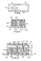
element 34 of Figure 2. - In Figures 8-9, there is shown an alternate construction of yet another suitably unequally sized, electrode configurations, wherein the applicator 10B includes a plurality of randomly placed or preferably uniformly aligned rows of a high tack,
impermeable gel 22a. Such an adhesive gel aids in retaining the patch on one's skin and inasmuch as some areas of the patch would thus be more tacky than other areas of the patch, such construction enables the manufacture of a patch wherein the adhesive gel 22ʹ has less adhesive strength than that of thegel 22a. By this arrangement, the patch may be easily removed from the skin and replaced thereon should one require removal and replacement of the same patch, say for example, upon bathing or showering, or even pursuant to a physician's instructions wherein it is desired to transmit a drug dosage periodically in lieu of a continuous steady state condition. - As best shown in Figure 9, the drug matrixes or reservoirs of the electrodes are represented by reference numerals 206ʹ and 206ʺ, and same are separated by a suitable
silicone barrier dam 208. The high tack zones orareas 22a are generally of a harder gel than that gel of 22ʹ. Thus, theseelements 22a which may be either of elongated fiber-like construction or of stubby spherical shape (not shown) they both serve the same identical purpose. However, as one construction may be easier or less expensive to fabricate than the other, neither one is more preferable than the other and both are considered within the scope of my invention. - Other electrode structures, suitable for use in making applicators of the invention include those electrodes shown in Figures 10-12, respectively as 10C, 10D and 10E. As illustrated in Figure 10, a plurality of conductive fiber-
like elements elements 22a contained in the electrodes of Figures 8 and 9. The primary purpose of such fiber structures is to bring the current flow more directly to the zone where the electrically induced mass transfer phenomena and drug delivery takes place. This is represented by thezone 230 and the reference arrows 232 (shown in phantom) illustrate in general the concentration gradient. Thus, as the area orzone 230 is depleted of drug, as a result of the mass transfer phenomena, this induces the drug to migrate from or out of thehigh concentration zone 202 to the depleted area or zone, as is best exemplified by thereference arrows 232. The transport speed is generally determined by the interaction of the drug and the media. This thus enables the patch to maintain low electrical mass transfer inzone 230, and it limits or or minimizes the amount of time the drug is exposed to the electrical forces. Therefore, most of the drug in the reservoir is not subjected to current as the mass transfer phenomena takes place only in the vicinity ofzone 230. Clearly, the fibers are prevented from extending transversely across the full height or depth of the electrode or patch construction as to do so would cause a short out at the skin and thus would cause an undesirable sensation.Also, the shapes of the fibers may suitably be varied or of the same configuration, such as elongated (220b) or tapering (220a and 220c). In addition, the fibers may extend fromelement 204 to thereservoir 206 or element 22ʹ, or they may extend fromelement 200 to element 22ʹ. Additionally, it will be appreciated that tack spots and/or the conductive fibers permit drug delivery from small patch areas and the osmotically replinishing of the drug as it migrates through the skin. - As best shown in Figure 11, plurality of micro-tubes (or holes) 254 are suitably randomly provided in a non-conductive, plastic-like inert area 250 (not unlike a sponge with a multiplicity of voids and passageways generally oriented in a vertical direction although not necessarily in straight lines). The
tubes 254 may optimally be provided at their ends with theplugs - Plug 252, for example, may form an ion-permeable gel which may take the form of an ion-selective retention gel. Alternatively plug 252 could also be a selective barrier against air,oxygen and other contaminants. The
plug 252 may also suitably contain appropriate buffers and/or enhancers or any other compounds which desirably are to be transmitted initially transdermally, such as a skin permeability enhancer. Such a plug arrangement, can facilitate a quick, fast acting dosage so as to provide for an immediate blood serum drug level dosage. Such a high rate of delivery is in contrast to a more normalized delivery rate of a transdermal drug electrically transported without the aid of any enhancers or the like. - Alternatively, conductive (such as carbon containing)
fibers 260 embedded in a suitablyinert material 250a may be provided betweenelement 204 and a suitably reverse plating cell 38ʹ. The reverse plating cell 38ʹ enables a different drug delivery sequence and/or enables one to provide for different delivery rates of drugs. Theinert material 250a with itstransverse fibers 260 can only conduct electricity in a direction perpendicular to its surface, and the individual fiber's resistance have an electrical current limiting effect. Thus, such an arrangement provides a so called "fail safe" mode of delivering current to the skin, i.e. the current density at the skin surface cannot increase above the "feel" threshold should the applicator patch become loose during use. Note that all of thedrugs 206 to be transported reside within thetubes 254. - Figure 12 represents an embodiment of an electrode for an applicator similar to that of Figure 11, but without the
conductive fibers 260,inert mass 250a, and reverse plating cell 38ʹ. Here, plug 141ʹ is of a suitably electrically resistive material as is the plug 141ʹ of Figure 11. - It will also be apparent that there are many
more fibers 260 thantubes 254, and both fibers and tubes are randomly disposed. Theconductive fibers 260 have a function similar to that of the electricallyresistive material 141, 141ʹ. - In a series of tests conducted using applicators made generally in accordance with that design exemplified by the "inactive" electrode shown in Figure 6, using drugs such as testosterone, tobramycin, and aspirin, the following tabled results were obtained from sampled blood and urine of rabbits which formed the test animals in all cases. The control represented patches or applicators without any power source, but containing drug. Note that the first two drugs were radiotagged, whereas aspirin was tested both as radiotagged and conventional or untagged, and the samples taken were assayed for the total radioactive count.
- Albino rabbits were employed for the tests, and each rabbit weighed at least six pounds. (Note: rabbits do not have sebaceous glands). The back of each rabbit's neck was shaved to permit better contact of the applicators and the skin or epidermis. The applicators were secured in place by an elastic bandage.
- Each applicator was of the same size (3" x 4") and equally divided, with one half being the cathodic or negatively charged electrode, and the other half being the anode or positively charged electrode; and the target drug was loaded equally into both halves of the applicator. Only one drug was employed in each test. The target drug was also dissolved in distilled water and 4 ml of the resultant solution was loaded into the patches.
- The blood samples were secured prior to initiation of drug delivery, and at hourly intervals for the next six hours. The urine samples were occasionally collected to determine if the drug was being metabolized and eliminated from the animals during the course of the experiments. Where more than one series of tests were employed using the same groups of animals, at least 36 hours elapsed between the end of one test series and the beginning of a second test in order to insure that there was no interference between each test series. In one series of tests, the patches were without electrical power, and in another series of tests, the patches were powered by table top power supplies for purposes of convenience and expediency.
- The control series, with no applied power, did not yield any levels of radioactivity in the sampled blood. When the table top battery supply was connected to the patch, the following results were obtained.

- The urine was collected into two batches. The first three hours of pooled urine per animal exhibited no radioactivity (less than one count per minute). The second three hours average radioactivity was 7 dpm.
- There was no noticeable transdermal delivery of trobramycin without applied power. The results over the six hours of testing ranged from 0 to 2 disintegrations per minute. When the table top power supply was applied to the patch, the results were noticeably different, as is seen hereinbelow.

- The urine samples demonstrated no radioactivity during the first three hours. The average radioactivity in the subsequent period was 2.5 dpm.
- As radioactively tagged aspirin was not obtainable, thus liquid aspirin was employed and assayed using conventional methods. The results for the powered delivery were as follows.

- It is clear from these tests that due to the migration phenomenon drugs can be transported transdermally using an electrically powered applicator, and that desired drug levels may be obtained by environmental optimization, i.e. pH, drug loading, current density, etc.
- It will also be appreciated that since both ionic and non-ionic drugs can be transdermally delivered, it may not be necessary to ionically charge a non-ionic drug, should it be desired to transdermally transport such a drug by an electrically powere applicator patch.
- Also, the applicators may be made with the same electrode configurations or with different designs, such as those constructions described herein. It is also within the scope of the present invention to have an applicator patch embodying three different electrode structures, such as that described with reference to Figure 7. Furthermore, although both an active and an inactive electrode are required for use with an electrophoresis mass transfer drug system, all of the electrodes may be active in those systems employed where either electroosmosis or both electroosmosis and electrophoretic systems are utilized to deliver one or more drugs into the blood stream.
- Although the present invention has been described in some detail by way of illustration and example for purposes of clari and understanding, it will, of course, be understood that vario changes and modifications may be made in the form, details, and arrangements of the parts without departing from the scope of the invention as set forth in the following claims.
Claims (39)
reservoir means, in at least one of said electrode elements of said applicator, containing said medicament and a plurality of high tack areas,
a circuit, including a power source, for supplying electric power to said electrodes and said reservoir means,
cover means partially enclosing at least said reservoir means, and
adhesive means for affixing said applicator to said skin, whereby an electrical circuit through the skin is formed when said applicator is affixed to said skin, thereby creating at least one physico/chemical mass transfer phenomenon which causes said at least one medicament to migrate through the skin.
at least two electrode elements forming said applicator separated from each other, by non-conductive and impervious barrier means,
reservoir means, in at least one of said electrode elements of said applicator, containing said medicament and a plurality of conductive elements extending at least partially across said reservoir means,
a circuit, including a power source, for supplying electric power to said electrodes and said reservoir means,
cover means partially enclosing at least said reservoir means, and
adhesive means for affixing said applicator to said skin, whereby an electrical circuit through the skin is formed when said applicator is affixed to said skin, thereby creating at least one physico/chemical mass transfer phenomenon which causes said at least one medicament to migrate through the skin.
at least two electrode elements forming said applicator separated from each other by non-conductive and impervious barrier means,
drug reservoir means, in at least one of said electrode elements of said applicator, having a plurality of micro-tubes,
a circuit, including a power source, for supplying electric power to said electrodes and said reservoir means,
cover means partially enclosing at least said reservoir means, and
adhesive means for affixing said applicator to said skin, whereby an electrical circuit through the skin is formed when said applicator is affixed to said skin, thereby creating at least one physico/chemical mass transfer phenomenon which causes said at least one medicament to migrate through the skin.
Priority Applications (2)
| Application Number | Priority Date | Filing Date | Title |
|---|---|---|---|
| EP92119093A EP0543241B1 (en) | 1986-03-14 | 1986-07-24 | Transdermal drug applicator and electrodes therefor |
| AT86110164T ATE89487T1 (en) | 1986-03-14 | 1986-07-24 | DEVICE FOR TRANSDERMAL APPLICATION OF MEDICATIONS AND RELATED ELECTRODES. |
Applications Claiming Priority (2)
| Application Number | Priority Date | Filing Date | Title |
|---|---|---|---|
| US83952386A | 1986-03-14 | 1986-03-14 | |
| US839523 | 2010-07-20 |
Related Child Applications (1)
| Application Number | Title | Priority Date | Filing Date |
|---|---|---|---|
| EP92119093.0 Division-Into | 1986-07-24 |
Publications (2)
| Publication Number | Publication Date |
|---|---|
| EP0240593A1 true EP0240593A1 (en) | 1987-10-14 |
| EP0240593B1 EP0240593B1 (en) | 1993-05-19 |
Family
ID=25279962
Family Applications (3)
| Application Number | Title | Priority Date | Filing Date |
|---|---|---|---|
| EP92119093A Expired - Lifetime EP0543241B1 (en) | 1986-03-14 | 1986-07-24 | Transdermal drug applicator and electrodes therefor |
| EP86110164A Expired - Lifetime EP0240593B1 (en) | 1986-03-14 | 1986-07-24 | Improved transdermal drug applicator and electrodes therefor |
| EP96115012A Ceased EP0749763A3 (en) | 1986-03-14 | 1986-07-24 | Transdermal drug applicator and electrodes therefor |
Family Applications Before (1)
| Application Number | Title | Priority Date | Filing Date |
|---|---|---|---|
| EP92119093A Expired - Lifetime EP0543241B1 (en) | 1986-03-14 | 1986-07-24 | Transdermal drug applicator and electrodes therefor |
Family Applications After (1)
| Application Number | Title | Priority Date | Filing Date |
|---|---|---|---|
| EP96115012A Ceased EP0749763A3 (en) | 1986-03-14 | 1986-07-24 | Transdermal drug applicator and electrodes therefor |
Country Status (9)
| Country | Link |
|---|---|
| EP (3) | EP0543241B1 (en) |
| JP (1) | JPH0647014B2 (en) |
| KR (1) | KR960001128B1 (en) |
| AT (2) | ATE89487T1 (en) |
| AU (1) | AU597890B2 (en) |
| BR (1) | BR8603859A (en) |
| CA (1) | CA1287665C (en) |
| DE (2) | DE3650607T2 (en) |
| MX (1) | MX172926B (en) |
Cited By (17)
| Publication number | Priority date | Publication date | Assignee | Title |
|---|---|---|---|---|
| EP0348765A1 (en) * | 1988-06-25 | 1990-01-03 | BASF Aktiengesellschaft | Adhesive plaster with an active agent |
| EP0445742A1 (en) * | 1990-03-05 | 1991-09-11 | Kowa Company, Ltd. | Electrotherapeutic device |
| US5125894A (en) * | 1990-03-30 | 1992-06-30 | Alza Corporation | Method and apparatus for controlled environment electrotransport |
| US5279543A (en) * | 1988-01-29 | 1994-01-18 | The Regents Of The University Of California | Device for iontophoretic non-invasive sampling or delivery of substances |
| US5362307A (en) * | 1989-01-24 | 1994-11-08 | The Regents Of The University Of California | Method for the iontophoretic non-invasive-determination of the in vivo concentration level of an inorganic or organic substance |
| US6004309A (en) * | 1990-03-30 | 1999-12-21 | Alza Corporation | Method and apparatus for controlled environment electrotransport |
| WO2000024455A1 (en) * | 1998-10-28 | 2000-05-04 | Cygnus, Inc. | Kit and method for quality control testing of an iontophoretic sampling system |
| US9687641B2 (en) | 2010-05-04 | 2017-06-27 | Corium International, Inc. | Method and device for transdermal delivery of parathyroid hormone using a microprojection array |
| US9962534B2 (en) | 2013-03-15 | 2018-05-08 | Corium International, Inc. | Microarray for delivery of therapeutic agent, methods of use, and methods of making |
| US10195409B2 (en) | 2013-03-15 | 2019-02-05 | Corium International, Inc. | Multiple impact microprojection applicators and methods of use |
| US10238848B2 (en) | 2007-04-16 | 2019-03-26 | Corium International, Inc. | Solvent-cast microprotrusion arrays containing active ingredient |
| US10245422B2 (en) | 2013-03-12 | 2019-04-02 | Corium International, Inc. | Microprojection applicators and methods of use |
| US10384045B2 (en) | 2013-03-15 | 2019-08-20 | Corium, Inc. | Microarray with polymer-free microstructures, methods of making, and methods of use |
| US10384046B2 (en) | 2013-03-15 | 2019-08-20 | Corium, Inc. | Microarray for delivery of therapeutic agent and methods of use |
| US10624843B2 (en) | 2014-09-04 | 2020-04-21 | Corium, Inc. | Microstructure array, methods of making, and methods of use |
| US10857093B2 (en) | 2015-06-29 | 2020-12-08 | Corium, Inc. | Microarray for delivery of therapeutic agent, methods of use, and methods of making |
| US11052231B2 (en) | 2012-12-21 | 2021-07-06 | Corium, Inc. | Microarray for delivery of therapeutic agent and methods of use |
Families Citing this family (13)
| Publication number | Priority date | Publication date | Assignee | Title |
|---|---|---|---|---|
| US5332577A (en) * | 1988-12-27 | 1994-07-26 | Dermamed | Transdermal administration to humans and animals |
| US5241925A (en) * | 1988-12-27 | 1993-09-07 | Dermamed | Apparatus and techniques for administering veterinary medicaments |
| US5324521A (en) * | 1989-12-18 | 1994-06-28 | Dermamed | Systems for transdermal administration of medicaments |
| US5445609A (en) * | 1993-05-28 | 1995-08-29 | Alza Corporation | Electrotransport agent delivery device having a disposable component and a removable liner |
| FR2709670B1 (en) * | 1993-09-10 | 1995-10-20 | Asulab Sa | Device in three modules for transdermal administration of drugs by electrophoresis or iontophoresis. |
| DE4404842A1 (en) * | 1994-02-16 | 1995-08-17 | Pierre Nicolas Dr Med Foss | Electrotherapeutic appts. with flexible skin electrode arrangement |
| JP3029629U (en) * | 1996-03-29 | 1996-10-01 | 株式会社エスピーアイ | Automotive awnings |
| US7828827B2 (en) | 2002-05-24 | 2010-11-09 | Corium International, Inc. | Method of exfoliation of skin using closely-packed microstructures |
| US7108681B2 (en) | 2000-10-16 | 2006-09-19 | Corium International, Inc. | Microstructures for delivering a composition cutaneously to skin |
| CA2560840C (en) | 2004-03-24 | 2014-05-06 | Corium International, Inc. | Transdermal delivery device |
| CA2676221C (en) | 2007-01-22 | 2016-12-20 | Corium International, Inc. | Applicators for microneedles |
| DE102007041557B4 (en) | 2007-08-29 | 2011-03-31 | Lts Lohmann Therapie-Systeme Ag | Transdermal therapeutic system containing elongated hollow bodies |
| WO2009048607A1 (en) | 2007-10-10 | 2009-04-16 | Corium International, Inc. | Vaccine delivery via microneedle arrays |
Citations (3)
| Publication number | Priority date | Publication date | Assignee | Title |
|---|---|---|---|---|
| EP0147524A1 (en) * | 1983-08-18 | 1985-07-10 | Drug Delivery Systems Inc. | Applicator for the non-invasive transcutaneous delivery of medicament |
| EP0178601A2 (en) * | 1984-10-12 | 1986-04-23 | Drug Delivery Systems Inc. | Transdermal drug applicator |
| WO1986007269A1 (en) * | 1985-06-10 | 1986-12-18 | Drug Delivery Systems Inc. | Programmable control and mounting system for transdermal drug applicator |
Family Cites Families (3)
| Publication number | Priority date | Publication date | Assignee | Title |
|---|---|---|---|---|
| US4325367A (en) * | 1977-06-13 | 1982-04-20 | Robert Tapper | Iontophoretic treatment apparatus |
| AU534533B2 (en) * | 1979-11-19 | 1984-02-02 | Tapper, R. | Iontophoresis apparatus |
| DE3266982D1 (en) * | 1981-03-05 | 1985-11-28 | Medtronic Inc | Iontophoretic device |
-
1986
- 1986-07-16 AU AU60222/86A patent/AU597890B2/en not_active Ceased
- 1986-07-23 CA CA000514514A patent/CA1287665C/en not_active Expired - Fee Related
- 1986-07-24 DE DE3650607T patent/DE3650607T2/en not_active Expired - Fee Related
- 1986-07-24 EP EP92119093A patent/EP0543241B1/en not_active Expired - Lifetime
- 1986-07-24 DE DE86110164T patent/DE3688463T2/en not_active Expired - Fee Related
- 1986-07-24 AT AT86110164T patent/ATE89487T1/en not_active IP Right Cessation
- 1986-07-24 EP EP86110164A patent/EP0240593B1/en not_active Expired - Lifetime
- 1986-07-24 EP EP96115012A patent/EP0749763A3/en not_active Ceased
- 1986-07-24 AT AT92119093T patent/ATE150652T1/en not_active IP Right Cessation
- 1986-07-31 KR KR1019860006303A patent/KR960001128B1/en not_active IP Right Cessation
- 1986-08-08 JP JP61186721A patent/JPH0647014B2/en not_active Expired - Lifetime
- 1986-08-13 BR BR8603859A patent/BR8603859A/en not_active IP Right Cessation
- 1986-08-28 MX MX003577A patent/MX172926B/en unknown
Patent Citations (3)
| Publication number | Priority date | Publication date | Assignee | Title |
|---|---|---|---|---|
| EP0147524A1 (en) * | 1983-08-18 | 1985-07-10 | Drug Delivery Systems Inc. | Applicator for the non-invasive transcutaneous delivery of medicament |
| EP0178601A2 (en) * | 1984-10-12 | 1986-04-23 | Drug Delivery Systems Inc. | Transdermal drug applicator |
| WO1986007269A1 (en) * | 1985-06-10 | 1986-12-18 | Drug Delivery Systems Inc. | Programmable control and mounting system for transdermal drug applicator |
Cited By (29)
| Publication number | Priority date | Publication date | Assignee | Title |
|---|---|---|---|---|
| US5730714A (en) * | 1988-01-29 | 1998-03-24 | The Regents Of The University Of California | Method for the iontophoretic non-invasive determination of the in vivo concentration level of glucose |
| US6714815B2 (en) | 1988-01-29 | 2004-03-30 | The Regents Of The University Of California | Method for the iontophoretic non-invasive determination of the in vivo concentration level of an inorganic or organic substance |
| US5279543A (en) * | 1988-01-29 | 1994-01-18 | The Regents Of The University Of California | Device for iontophoretic non-invasive sampling or delivery of substances |
| US6542765B1 (en) | 1988-01-29 | 2003-04-01 | The Regent Of The University Of California | Method for the iontophoretic non-invasive determination of the in vivo concentration level of an inorganic or organic substance |
| EP0348765A1 (en) * | 1988-06-25 | 1990-01-03 | BASF Aktiengesellschaft | Adhesive plaster with an active agent |
| US5362307A (en) * | 1989-01-24 | 1994-11-08 | The Regents Of The University Of California | Method for the iontophoretic non-invasive-determination of the in vivo concentration level of an inorganic or organic substance |
| EP0445742A1 (en) * | 1990-03-05 | 1991-09-11 | Kowa Company, Ltd. | Electrotherapeutic device |
| US5376107A (en) * | 1990-03-05 | 1994-12-27 | Kowa Co., Ltd. | Electrotherapeutic device |
| US5591124A (en) * | 1990-03-30 | 1997-01-07 | Alza Corporation | Method and apparatus for controlled environment electrotransport |
| US5622530A (en) * | 1990-03-30 | 1997-04-22 | Alza Corporation | Method and apparatus for controlled environment electrotransport |
| US6004309A (en) * | 1990-03-30 | 1999-12-21 | Alza Corporation | Method and apparatus for controlled environment electrotransport |
| US6289241B1 (en) | 1990-03-30 | 2001-09-11 | Alza Corporation | Method and apparatus for controlled environment electrotransport |
| US5443442A (en) * | 1990-03-30 | 1995-08-22 | Alza Corporation | Method and apparatus for controlled environment electrotransport |
| US5125894A (en) * | 1990-03-30 | 1992-06-30 | Alza Corporation | Method and apparatus for controlled environment electrotransport |
| WO2000024455A1 (en) * | 1998-10-28 | 2000-05-04 | Cygnus, Inc. | Kit and method for quality control testing of an iontophoretic sampling system |
| US6391643B1 (en) | 1998-10-28 | 2002-05-21 | Cygnus, Inc. | Kit and method for quality control testing of an iontophoretic sampling system |
| US10238848B2 (en) | 2007-04-16 | 2019-03-26 | Corium International, Inc. | Solvent-cast microprotrusion arrays containing active ingredient |
| US9687641B2 (en) | 2010-05-04 | 2017-06-27 | Corium International, Inc. | Method and device for transdermal delivery of parathyroid hormone using a microprojection array |
| US11419816B2 (en) | 2010-05-04 | 2022-08-23 | Corium, Inc. | Method and device for transdermal delivery of parathyroid hormone using a microprojection array |
| US11052231B2 (en) | 2012-12-21 | 2021-07-06 | Corium, Inc. | Microarray for delivery of therapeutic agent and methods of use |
| US10245422B2 (en) | 2013-03-12 | 2019-04-02 | Corium International, Inc. | Microprojection applicators and methods of use |
| US11110259B2 (en) | 2013-03-12 | 2021-09-07 | Corium, Inc. | Microprojection applicators and methods of use |
| US9962534B2 (en) | 2013-03-15 | 2018-05-08 | Corium International, Inc. | Microarray for delivery of therapeutic agent, methods of use, and methods of making |
| US10195409B2 (en) | 2013-03-15 | 2019-02-05 | Corium International, Inc. | Multiple impact microprojection applicators and methods of use |
| US10384045B2 (en) | 2013-03-15 | 2019-08-20 | Corium, Inc. | Microarray with polymer-free microstructures, methods of making, and methods of use |
| US10384046B2 (en) | 2013-03-15 | 2019-08-20 | Corium, Inc. | Microarray for delivery of therapeutic agent and methods of use |
| US11565097B2 (en) | 2013-03-15 | 2023-01-31 | Corium Pharma Solutions, Inc. | Microarray for delivery of therapeutic agent and methods of use |
| US10624843B2 (en) | 2014-09-04 | 2020-04-21 | Corium, Inc. | Microstructure array, methods of making, and methods of use |
| US10857093B2 (en) | 2015-06-29 | 2020-12-08 | Corium, Inc. | Microarray for delivery of therapeutic agent, methods of use, and methods of making |
Also Published As
| Publication number | Publication date |
|---|---|
| EP0543241A1 (en) | 1993-05-26 |
| CA1287665C (en) | 1991-08-13 |
| ATE89487T1 (en) | 1993-06-15 |
| ATE150652T1 (en) | 1997-04-15 |
| EP0749763A2 (en) | 1996-12-27 |
| DE3650607T2 (en) | 1997-10-02 |
| BR8603859A (en) | 1987-11-17 |
| MX172926B (en) | 1994-01-24 |
| EP0749763A3 (en) | 1997-01-08 |
| EP0240593B1 (en) | 1993-05-19 |
| KR960001128B1 (en) | 1996-01-19 |
| JPH0647014B2 (en) | 1994-06-22 |
| DE3688463D1 (en) | 1993-06-24 |
| DE3688463T2 (en) | 1993-12-02 |
| JPS62213763A (en) | 1987-09-19 |
| EP0543241B1 (en) | 1997-03-26 |
| AU6022286A (en) | 1987-09-17 |
| KR870008595A (en) | 1987-10-19 |
| DE3650607D1 (en) | 1997-04-30 |
| AU597890B2 (en) | 1990-06-14 |
Similar Documents
| Publication | Publication Date | Title |
|---|---|---|
| US4921475A (en) | Transdermal drug patch with microtubes | |
| US4640689A (en) | Transdermal drug applicator and electrodes therefor | |
| US5931804A (en) | Transdermal drug applicator and electrodes therefor | |
| US5087240A (en) | Transdermal drug patch with conductive fibers | |
| US4919648A (en) | High tack drug patch | |
| US5651768A (en) | Transdermal drug applicator and electrodes therefor | |
| EP0543241B1 (en) | Transdermal drug applicator and electrodes therefor | |
| KR940000071B1 (en) | Transdermal drug applicator | |
| EP0147524B1 (en) | Applicator for the non-invasive transcutaneous delivery of medicament | |
| US6129696A (en) | Transdermal drug applicator | |
| CA1181490A (en) | Ion mobility limiting iontophoretic bioelectrode | |
| US5284471A (en) | Electrode and method used for iontophoresis | |
| US5591123A (en) | Programmable control mounting system for transdermal drug applicator | |
| AU644793B2 (en) | Method and apparatus for iontophoretic drug delivery | |
| US5746711A (en) | Programmable control and mounting system for transdermal drug applicator | |
| EP0337642A2 (en) | Transdermal drug delivery device |
Legal Events
| Date | Code | Title | Description |
|---|---|---|---|
| PUAI | Public reference made under article 153(3) epc to a published international application that has entered the european phase |
Free format text: ORIGINAL CODE: 0009012 |
|
| AK | Designated contracting states |
Kind code of ref document: A1 Designated state(s): AT BE CH DE FR GB IT LI LU NL SE |
|
| 17P | Request for examination filed |
Effective date: 19880317 |
|
| 17Q | First examination report despatched |
Effective date: 19910313 |
|
| GRAA | (expected) grant |
Free format text: ORIGINAL CODE: 0009210 |
|
| ITF | It: translation for a ep patent filed |
Owner name: BARZANO' E ZANARDO ROMA S.P.A. |
|
| AK | Designated contracting states |
Kind code of ref document: B1 Designated state(s): AT BE CH DE FR GB IT LI LU NL SE |
|
| REF | Corresponds to: |
Ref document number: 89487 Country of ref document: AT Date of ref document: 19930615 Kind code of ref document: T |
|
| XX | Miscellaneous (additional remarks) |
Free format text: TEILANMELDUNG 92119093.0 EINGEREICHT AM 24/07/86. |
|
| REF | Corresponds to: |
Ref document number: 3688463 Country of ref document: DE Date of ref document: 19930624 |
|
| ET | Fr: translation filed | ||
| PLBE | No opposition filed within time limit |
Free format text: ORIGINAL CODE: 0009261 |
|
| STAA | Information on the status of an ep patent application or granted ep patent |
Free format text: STATUS: NO OPPOSITION FILED WITHIN TIME LIMIT |
|
| 26N | No opposition filed | ||
| EPTA | Lu: last paid annual fee | ||
| EAL | Se: european patent in force in sweden |
Ref document number: 86110164.0 |
|
| PGFP | Annual fee paid to national office [announced via postgrant information from national office to epo] |
Ref country code: GB Payment date: 20010614 Year of fee payment: 16 |
|
| PGFP | Annual fee paid to national office [announced via postgrant information from national office to epo] |
Ref country code: AT Payment date: 20010615 Year of fee payment: 16 |
|
| PGFP | Annual fee paid to national office [announced via postgrant information from national office to epo] |
Ref country code: NL Payment date: 20010618 Year of fee payment: 16 |
|
| PGFP | Annual fee paid to national office [announced via postgrant information from national office to epo] |
Ref country code: LU Payment date: 20010627 Year of fee payment: 16 |
|
| PGFP | Annual fee paid to national office [announced via postgrant information from national office to epo] |
Ref country code: FR Payment date: 20010702 Year of fee payment: 16 |
|
| PGFP | Annual fee paid to national office [announced via postgrant information from national office to epo] |
Ref country code: SE Payment date: 20010703 Year of fee payment: 16 |
|
| PGFP | Annual fee paid to national office [announced via postgrant information from national office to epo] |
Ref country code: DE Payment date: 20010731 Year of fee payment: 16 |
|
| PGFP | Annual fee paid to national office [announced via postgrant information from national office to epo] |
Ref country code: BE Payment date: 20010814 Year of fee payment: 16 |
|
| PGFP | Annual fee paid to national office [announced via postgrant information from national office to epo] |
Ref country code: CH Payment date: 20010927 Year of fee payment: 16 |
|
| REG | Reference to a national code |
Ref country code: GB Ref legal event code: IF02 |
|
| PG25 | Lapsed in a contracting state [announced via postgrant information from national office to epo] |
Ref country code: LU Free format text: LAPSE BECAUSE OF NON-PAYMENT OF DUE FEES Effective date: 20020724 Ref country code: GB Free format text: LAPSE BECAUSE OF NON-PAYMENT OF DUE FEES Effective date: 20020724 Ref country code: AT Free format text: LAPSE BECAUSE OF NON-PAYMENT OF DUE FEES Effective date: 20020724 |
|
| PG25 | Lapsed in a contracting state [announced via postgrant information from national office to epo] |
Ref country code: SE Free format text: LAPSE BECAUSE OF NON-PAYMENT OF DUE FEES Effective date: 20020725 |
|
| PG25 | Lapsed in a contracting state [announced via postgrant information from national office to epo] |
Ref country code: LI Free format text: LAPSE BECAUSE OF NON-PAYMENT OF DUE FEES Effective date: 20020731 Ref country code: CH Free format text: LAPSE BECAUSE OF NON-PAYMENT OF DUE FEES Effective date: 20020731 Ref country code: BE Free format text: LAPSE BECAUSE OF NON-PAYMENT OF DUE FEES Effective date: 20020731 |
|
| BERE | Be: lapsed |
Owner name: *DRUG DELIVERY SYSTEMS INC. Effective date: 20020731 |
|
| PG25 | Lapsed in a contracting state [announced via postgrant information from national office to epo] |
Ref country code: NL Free format text: LAPSE BECAUSE OF NON-PAYMENT OF DUE FEES Effective date: 20030201 Ref country code: DE Free format text: LAPSE BECAUSE OF NON-PAYMENT OF DUE FEES Effective date: 20030201 |
|
| EUG | Se: european patent has lapsed | ||
| REG | Reference to a national code |
Ref country code: CH Ref legal event code: PL |
|
| GBPC | Gb: european patent ceased through non-payment of renewal fee |
Effective date: 20020724 |
|
| PG25 | Lapsed in a contracting state [announced via postgrant information from national office to epo] |
Ref country code: FR Free format text: LAPSE BECAUSE OF NON-PAYMENT OF DUE FEES Effective date: 20030331 |
|
| NLV4 | Nl: lapsed or anulled due to non-payment of the annual fee |
Effective date: 20030201 |
|
| REG | Reference to a national code |
Ref country code: FR Ref legal event code: ST |
|
| PG25 | Lapsed in a contracting state [announced via postgrant information from national office to epo] |
Ref country code: IT Free format text: LAPSE BECAUSE OF NON-PAYMENT OF DUE FEES;WARNING: LAPSES OF ITALIAN PATENTS WITH EFFECTIVE DATE BEFORE 2007 MAY HAVE OCCURRED AT ANY TIME BEFORE 2007. THE CORRECT EFFECTIVE DATE MAY BE DIFFERENT FROM THE ONE RECORDED. Effective date: 20050724 |