EP0332310A2 - Sterilant concentrate injection system - Google Patents
Sterilant concentrate injection system Download PDFInfo
- Publication number
- EP0332310A2 EP0332310A2 EP89301574A EP89301574A EP0332310A2 EP 0332310 A2 EP0332310 A2 EP 0332310A2 EP 89301574 A EP89301574 A EP 89301574A EP 89301574 A EP89301574 A EP 89301574A EP 0332310 A2 EP0332310 A2 EP 0332310A2
- Authority
- EP
- European Patent Office
- Prior art keywords
- ampule
- vent aperture
- vent
- sterilant
- water
- Prior art date
- Legal status (The legal status is an assumption and is not a legal conclusion. Google has not performed a legal analysis and makes no representation as to the accuracy of the status listed.)
- Granted
Links
Images


Classifications
-
- A—HUMAN NECESSITIES
- A61—MEDICAL OR VETERINARY SCIENCE; HYGIENE
- A61L—METHODS OR APPARATUS FOR STERILISING MATERIALS OR OBJECTS IN GENERAL; DISINFECTION, STERILISATION OR DEODORISATION OF AIR; CHEMICAL ASPECTS OF BANDAGES, DRESSINGS, ABSORBENT PADS OR SURGICAL ARTICLES; MATERIALS FOR BANDAGES, DRESSINGS, ABSORBENT PADS OR SURGICAL ARTICLES
- A61L2/00—Methods or apparatus for disinfecting or sterilising materials or objects other than foodstuffs or contact lenses; Accessories therefor
- A61L2/24—Apparatus using programmed or automatic operation
-
- A—HUMAN NECESSITIES
- A01—AGRICULTURE; FORESTRY; ANIMAL HUSBANDRY; HUNTING; TRAPPING; FISHING
- A01N—PRESERVATION OF BODIES OF HUMANS OR ANIMALS OR PLANTS OR PARTS THEREOF; BIOCIDES, e.g. AS DISINFECTANTS, AS PESTICIDES OR AS HERBICIDES; PEST REPELLANTS OR ATTRACTANTS; PLANT GROWTH REGULATORS
- A01N25/00—Biocides, pest repellants or attractants, or plant growth regulators, characterised by their forms, or by their non-active ingredients or by their methods of application, e.g. seed treatment or sequential application; Substances for reducing the noxious effect of the active ingredients to organisms other than pests
- A01N25/34—Shaped forms, e.g. sheets, not provided for in any other sub-group of this main group
-
- A—HUMAN NECESSITIES
- A61—MEDICAL OR VETERINARY SCIENCE; HYGIENE
- A61L—METHODS OR APPARATUS FOR STERILISING MATERIALS OR OBJECTS IN GENERAL; DISINFECTION, STERILISATION OR DEODORISATION OF AIR; CHEMICAL ASPECTS OF BANDAGES, DRESSINGS, ABSORBENT PADS OR SURGICAL ARTICLES; MATERIALS FOR BANDAGES, DRESSINGS, ABSORBENT PADS OR SURGICAL ARTICLES
- A61L2/00—Methods or apparatus for disinfecting or sterilising materials or objects other than foodstuffs or contact lenses; Accessories therefor
- A61L2/16—Methods or apparatus for disinfecting or sterilising materials or objects other than foodstuffs or contact lenses; Accessories therefor using chemical substances
- A61L2/18—Liquid substances or solutions comprising solids or dissolved gases
-
- A—HUMAN NECESSITIES
- A61—MEDICAL OR VETERINARY SCIENCE; HYGIENE
- A61L—METHODS OR APPARATUS FOR STERILISING MATERIALS OR OBJECTS IN GENERAL; DISINFECTION, STERILISATION OR DEODORISATION OF AIR; CHEMICAL ASPECTS OF BANDAGES, DRESSINGS, ABSORBENT PADS OR SURGICAL ARTICLES; MATERIALS FOR BANDAGES, DRESSINGS, ABSORBENT PADS OR SURGICAL ARTICLES
- A61L2/00—Methods or apparatus for disinfecting or sterilising materials or objects other than foodstuffs or contact lenses; Accessories therefor
- A61L2/16—Methods or apparatus for disinfecting or sterilising materials or objects other than foodstuffs or contact lenses; Accessories therefor using chemical substances
- A61L2/20—Gaseous substances, e.g. vapours
-
- B—PERFORMING OPERATIONS; TRANSPORTING
- B65—CONVEYING; PACKING; STORING; HANDLING THIN OR FILAMENTARY MATERIAL
- B65D—CONTAINERS FOR STORAGE OR TRANSPORT OF ARTICLES OR MATERIALS, e.g. BAGS, BARRELS, BOTTLES, BOXES, CANS, CARTONS, CRATES, DRUMS, JARS, TANKS, HOPPERS, FORWARDING CONTAINERS; ACCESSORIES, CLOSURES, OR FITTINGS THEREFOR; PACKAGING ELEMENTS; PACKAGES
- B65D77/00—Packages formed by enclosing articles or materials in preformed containers, e.g. boxes, cartons, sacks or bags
- B65D77/22—Details
- B65D77/225—Pressure relief-valves incorporated in a container wall, e.g. valves comprising at least one elastic element
-
- B—PERFORMING OPERATIONS; TRANSPORTING
- B65—CONVEYING; PACKING; STORING; HANDLING THIN OR FILAMENTARY MATERIAL
- B65D—CONTAINERS FOR STORAGE OR TRANSPORT OF ARTICLES OR MATERIALS, e.g. BAGS, BARRELS, BOTTLES, BOXES, CANS, CARTONS, CRATES, DRUMS, JARS, TANKS, HOPPERS, FORWARDING CONTAINERS; ACCESSORIES, CLOSURES, OR FITTINGS THEREFOR; PACKAGING ELEMENTS; PACKAGES
- B65D81/00—Containers, packaging elements, or packages, for contents presenting particular transport or storage problems, or adapted to be used for non-packaging purposes after removal of contents
- B65D81/32—Containers, packaging elements, or packages, for contents presenting particular transport or storage problems, or adapted to be used for non-packaging purposes after removal of contents for packaging two or more different materials which must be maintained separate prior to use in admixture
- B65D81/3216—Rigid containers disposed one within the other
Definitions
- the present invention relates to ampule systems for maintaining components, particularly reactive components and reagents, separated until immediately prior to use. It finds particular application in conjunction with sterilant systems in which a peracetic sterilant as well as buffers and corrosion inhibitors are diluted or dissolved immediately prior to a sterilizing operation. However, it is to be appreciated that the present invention will find utility in other multi-component systems which are intermixed in preparation for use, such as photographic systems, coating systems, medications, and the like.
- Instruments and equipment which could not withstand the temperature of an autoclave were commonly sterilized with ethylene oxide gas. After the equipment was sealed in a sterilizing chamber, the highly toxic ethylene oxide gas was introduced under pressure and allowed to remain for a couple of hours, as was appropriate to the selected sterilizing cycle. After the sterilizing cycle, the equipment could not be utilized until absorbed ethylene oxide was removed. This generally required about 12 to 16 hours in a vacuum or about 72 hours in ambient atmospheric conditions.
- Liquid sterilization systems were also available for equipment which could not withstand the autoclave or the ethylene oxide systems. However, most were manually performed. That is, the equipment was immersed in a vat or tank that had been filled with a sterilizing solution, such as stabilized hydrogen peroxide or glutaraldehyde. However, because long immersion times on the order of 6 to 10 hours, were commonly required for sterilization, the liquid systems were more commonly used for disinfecting. Because the liquid sterilizing or disinfecting agents were toxic to human tissue, the equipment had to be rinsed before it could be used with human patients. Frequently, non-sterile tap water was used as the rinse.
- a sterilizing solution such as stabilized hydrogen peroxide or glutaraldehyde.
- the liquid systems were more commonly used for disinfecting. Because the liquid sterilizing or disinfecting agents were toxic to human tissue, the equipment had to be rinsed before it could be used with human patients. Frequently, non-sterile tap water was used as the rinse.
- Sterilization connotes the absence of all life forms including bacterial endosphores which are the living organisms most resistant to known sterilants.
- disinfection only connotes the absence of pathogenic life forms.
- establishing the absence of all life forms for sterilization is more readily documented and controlled than the elimination of pathogenic but not all life forms for disinfection.
- bacterial spores are the life form which is most resistant to sterilants, they are commonly used as a reproducible, stable indicators of the effectiveness of a sterilization product.
- a sterility assurance level (SAL) of less than or equal to one chance in one million of having an item contaminated by a bacteria spore is generally regarded as the minimum acceptable level for medical devices.
- SAL sterility assurance level
- this level of assurance is obtained by a establishing the exposure time required to sterilize a given quantity of bacterial endosphores known to be resistant to the sterilant.
- the destruction rate of the spore is commonly logrythmic.
- D value From the logrythmic destruction rate, commonly denoted by a D value, the exposure time required for an insurance level of one in a million (10 ⁇ 6) can be readily calculated. Because pathogenic microorganisms, which are mostly vegetative forms of bacteria, do not have the stability to derive a D value or its equivalent, there is no readily available biological indicator to show the effectiveness of a disinfectant.
- a new and improved reactive agent dispensing system which overcomes the above referenced sterilizer problems and analogous problems and other equipment in which reactive agents are released contemporaneously with use.
- a spill resistant, vented ampule is provided.
- a vent passage defines an vent aperture at one end.
- a sealed exterior wall defines an interior volume surrounding the vent aperture such that the vent aperture is generally centrally located in the interior volume. The exterior wall is sealed to the vent passage such that the vent aperture provides the only ingress and egress to the interior volume.
- a gas permeable, fluid blocking membrane is mounted across the vent aperture. In this manner, gas is vented from the interior volume but the leakage of fluid is retarded.
- a volume of a liquid reagent which is less than half of the interior volume is contained within the ampule. The liquid volume is selected such that a top surface of the liquid is below the vent aperture with the ampule disposed in any orientation.
- a siphon extraction system for drawing the liquid from the ampule.
- a small bore tubular member is passed through the vent passage and into the interior volume.
- the tubular member is connected with an aspirator for withdrawing the liquid from the ampule and intermixing it with a second reagent.
- the first reagent is a strong sterilant concentrate such as peracetic acid and the second reagent is a dilutant such as water.
- the water and aspirated sterilant concentrate are circulated through a container holding an item to be sterilized and through a tubing system which interconnects the container with a source of sterile rinse water until the item, the interior of the container, and the tubing system are all sterilized.
- the sterile rinse solution cannot carry bacterial contaminants from the tubing into contact with the sterilized item during a rinse portion of the sterilizing cycle.
- One advantage of the present invention is that a sterilizing system is provided that assures sterility.
- Another advantage of the present invention is that a one dose sterilant cartridge is provided to assure proper reagent formulation and eliminate operator error.
- Yet another advantage of the present invention is that it provides a vented, liquid containing ampule which may be disposed in any orientation without leaking liquid.
- a dilutant or water source 10 supplies water or other fluid reagents.
- the water source includes a length of tubing 12 connected with a water spigot or other building plumbing and a control valve 14 for selectively preventing and permitting the flow of water to a water sterilizing means 16 .
- the water sterilizing means is a filter which removes particulates which are as large or larger than bacteria.
- a tubing system connects the filter with a container or module 20 for receiving an item to be sterilized.
- the container is defined by a removable tray 22 configured in accordance with the item to be sterilized, e.g. an endoscope.
- a lid 24 is sealed to the tray by a resilient gasket 26 to complete the container.
- a transparent window 28 is defined the in the lid.
- sterile water flows through the tubing system filling itself and the container 20 .
- the water flows through a spray nozzle 30 and a container distribution manifold 32 into the container and a reagent receiving well 34 .
- vent lines 36 are filled with excess water and discharged through a check valve 38 into a drain 40 .
- a reagent introduction system 42 selectively supplies sterilant, buffer, detergent, and corrosion inhibitors to the dilutant. More specifically, an aspirator 44 selectively withdraws sterilant concentrate from an ampule 46 . Powdered reagent received in the well 34 is dissolved as water flows in from the container.
- pump 50 selectively draws water from the container 20 through the well 34 and aspirator 44 . Recirculating the water dissolves the powdered reagents and aspirates the sterilant from the ampule and circulates the sterilant and reagents through the tubing system 18 .
- the vent line 36 is very short and of a substantial diameter such that the solution is circulated over exposed services of the drain check valve 38 and a vent check valve 52 .
- a heating coil 54 adjusts the temperature of the solution. Recirculation continues until the item, the interior of the container, and all exposed surfaces of the tubing system and valves are sterilized.
- sterile air is drawn into the system through an air sterilizing means - preferably a filter that removes any particles the size of a bacteria or larger.
- the fill valve 14 is opened and the drain valve 56 is closed such that the sterile filter 16 provides a source of sterile rinse. Note that the sterile rinse passes only along sterilized surfaces to assure sterility.
- the pump 50 circulates the sterile rinse throughout the system. Sterile rinse is drained by opening drain valve 56 again. By closing a valve 60 , the pump 50 functions to pump liquid from the system out the drain 40 . Additional drain lines (not shown) and aspirators or pumps (not shown) may be provided for removing liquid from all regions of the system.
- the sterilant aspirator system 42 includes a hollow, tubular needle or tube 70 which is inserted into the ampule to withdraw the sterilant.
- the needle 70 is connected with arm 72 which selectively swings the needle into and out of alignment with the ampule 46 .
- a vertical tubular portion 74 is telescopically received in a stationary tubular portion 86 .
- a coil spring 78 biases the arm tubular portion upward, hence, the needle 70 out of contact with the ampule.
- closing the lid 24 biases the arm downward against the coil spring 78 forcing the needle 70 into the ampule.
- Water pumped through the aspirator 44 aspirates the sterilant from the ampule into the fluid flow.
- the aspiration rate is selected such that the sterilant is aspirated gradually over the time required to circulate the water around the system one time.
- the sterilant ampule 46 has an exterior wall 80 which defines an interior volume 82 therein.
- a linear vent passage 84 integral with the exterior wall defines a passage extending linearly from the exterior to a vent aperture 86 .
- the vent passage extends linearly along a first axis 88 to act as a guide for the needle 70 . In this manner, the needle 70 passes through the vent aperture 86 into the interior volume.
- the exterior wall includes a circularly cylindrical peripheral wall 90 a minimum radius r from the first axis. End walls 92 and 94 extend generally transverse to the axis 88 and are integrally sealed to the peripheral wall.
- the vent aperture 86 is centrally disposed in the volume. More specifically, the vent aperture 86 is disposed a minimum radial distance r from the peripheral wall and generally a height h from each end wall. The ampule is charged less than half full with a fluid sterilant 96 such that its upper surface 98 is disposed below the vent aperture 86 .
- the interior volume 82 is configured relative to the volume of the sterilant such that the sterilant depth is always less than h and r regardless of the orientation of the ampule. In this manner, the liquid does not leak from the vent aperture 86 regardless of the orientation of the ampule 46 .
- a porous membrane 100 is disposed across the vent aperture 86 .
- the membrane is a fine woven material which has a median pore size sufficiently small compared to the drop size and wetting ability or surface tension of the liquid sterilant on the fiber material that the sterilant is effectively blocked from passing therethrough. Similarly, water is prevented from flowing freely into the ampule.
- the needle 70 passes the vent aperture 86 , its cambered end distorts the woven porous material moving the fibers out of its way. The natural resiliency of the fibers tends to return them to their original position when the needle is withdrawn. Any sterilant residue is held in the ampule by the position of the vent aperture 86 and the membrane 100 . In this manner, after the sterilization cycle is complete, the operator is protected from contacting the full strength sterilant concentrate directly. Analogously, no dilution of the sterilant concentrate occurs if a sterilizing cycle is aborted before aspiration starts.
- the ampule 46 is disposed in the bottom of a see-through larger container 110 .
- the container 110 has a peel-off top 112 which provides access to its contents.
- the container is shaped such that the ampule 46 fits snugly in the bottom and other powdered reagents 114 are disposed on top.
- the sterilizer arm 72 is swung out of the way and the powdery agents are poured into the well 34 .
- the ampule 46 is supported by rods or other ampule supporting means 116 in a preselected position in the well.
- the ampule is symmetric, thus assuring a central position of the vent aperture 86 .
- the support means 126 may include a key or key means which interacts with a selected portion of the ampule to assure proper alignment and positioning.
- the aspirator arm 72 is swung and locked until the needle 70 is directly over the vent aperture 86 . Because the ampule is accurately positioned in the well, the aspirator arm is adjusted to lock itself in the aligned position without hand aligning by the operator.
- the lid 24 is closed as in FIGURE 5D, the lid cams the aspirator arm against the coil spring 78 moving the tip of the needle 70 through the vent aperture into the proper position within the ampule.
- the ampule may have a small well directly in line with the vent to accommodate the tip of the aspirator needle and assure more complete emptying of the ampule.
- the powdered materials include buffers, detergents, and anti-corrosive agents.
- the anti-corrosive agents are selected in accordance with the selected sterilant and the nature of the materials in the sterilized items, such as brass fittings, that might be subject to corrosion.
- the sterilant is peracetic acid. Peracetic acid tends to liberate small quantities of oxygen during transportation and storage. Accordingly, the vent 86 insures that the pressure within the ampule does not become so great that it ruptures. High pressure could also cause spraying of the sterilant upon entry by the needle 70 .
- the ampule may take various shapes.
- the exterior wall 80 may be spherical.
- the vent aperture is still disposed in the center of the sphere and the fill level is such that the depth of the sterilant is smaller than the radius of the spherical interior volume.
- the vent aperture may be disposed eccentrically. However, the vent aperture is still disposed sufficiently close to the center of the interior volume that for the volume of sterilant provided, the upper surface of the sterilant always remains below the vent aperture.
- the ampule may have a groove or key way 120 in the exterior wall or a groove or aperture 122 in an exterior flange to assure that the ampule is disposed in a preselected alignment.
- a sufficiently fanciful or arbitrary exterior shape or key pattern protection can be had against inserting generally round ampules from other equipment which might contain substances other than sterilants.
- the sterilant, buffer, detergent, anti-corrosives, and other reagents may be retrieved from a two compartment container in other ways.
- the liquid containing ampule 46 may be mounted in the upper portion of a clear plastic cup 110 with the powdered components or reagents 114 in the lower portion.
- the powdered components are selected to include a material which changes color upon exposure to the liquid components. In this manner, a visual check is provided that the liquid components have not leaked into the powdered components.
- a vent 124 in the outer cup provides communication between the ampule and the atmosphere.
- a first puncturing ram 130 can extend into the lower part of the cup to introduce water or other dilutant into the cup and dissolve the powdered reagents. Additional water flow into the cup may be had when a first cutter 132 cuts the cup allowing water pumped into the well to circulate through the powder region of the cup. Movement of additional cutters 134 pierce both the cup and the sterilant ampule. In this manner, the powdered ingredients can be dissolved and mixed with recirculating water or other dilutant before the sterilant is released.
- cutters 132 and 134 are mounted on a common shaft 136 which is incrementally rotated to cause staged cutting of the cup and the ampule.
Abstract
Description
- The present invention relates to ampule systems for maintaining components, particularly reactive components and reagents, separated until immediately prior to use. It finds particular application in conjunction with sterilant systems in which a peracetic sterilant as well as buffers and corrosion inhibitors are diluted or dissolved immediately prior to a sterilizing operation. However, it is to be appreciated that the present invention will find utility in other multi-component systems which are intermixed in preparation for use, such as photographic systems, coating systems, medications, and the like.
- Heretofore, most medical facilities have used steam autoclave sterilization systems. Commonly, medical instruments and equipment were transported to a central sterilizing facility where they were sterilized under the supervision of sterilizing room technicians. In a steam autoclave, which typically has a cycle time of one to two hours, the equipment was subject to superheated steam at high pressures. After an appropriate sterilizing duration, the autoclave was depressurized and cooled.
- Instruments and equipment which could not withstand the temperature of an autoclave were commonly sterilized with ethylene oxide gas. After the equipment was sealed in a sterilizing chamber, the highly toxic ethylene oxide gas was introduced under pressure and allowed to remain for a couple of hours, as was appropriate to the selected sterilizing cycle. After the sterilizing cycle, the equipment could not be utilized until absorbed ethylene oxide was removed. This generally required about 12 to 16 hours in a vacuum or about 72 hours in ambient atmospheric conditions.
- Liquid sterilization systems were also available for equipment which could not withstand the autoclave or the ethylene oxide systems. However, most were manually performed. That is, the equipment was immersed in a vat or tank that had been filled with a sterilizing solution, such as stabilized hydrogen peroxide or glutaraldehyde. However, because long immersion times on the order of 6 to 10 hours, were commonly required for sterilization, the liquid systems were more commonly used for disinfecting. Because the liquid sterilizing or disinfecting agents were toxic to human tissue, the equipment had to be rinsed before it could be used with human patients. Frequently, non-sterile tap water was used as the rinse.
- Sterilization connotes the absence of all life forms including bacterial endosphores which are the living organisms most resistant to known sterilants. By contrast, disinfection only connotes the absence of pathogenic life forms. As is to be appreciated, establishing the absence of all life forms for sterilization is more readily documented and controlled than the elimination of pathogenic but not all life forms for disinfection.
- Because bacterial spores are the life form which is most resistant to sterilants, they are commonly used as a reproducible, stable indicators of the effectiveness of a sterilization product. For medical sterilizers, a sterility assurance level (SAL) of less than or equal to one chance in one million of having an item contaminated by a bacteria spore is generally regarded as the minimum acceptable level for medical devices. In practice, this level of assurance is obtained by a establishing the exposure time required to sterilize a given quantity of bacterial endosphores known to be resistant to the sterilant. The destruction rate of the spore is commonly logrythmic. From the logrythmic destruction rate, commonly denoted by a D value, the exposure time required for an insurance level of one in a million (10⁻⁶) can be readily calculated. Because pathogenic microorganisms, which are mostly vegetative forms of bacteria, do not have the stability to derive a D value or its equivalent, there is no readily available biological indicator to show the effectiveness of a disinfectant.
- In accordance with the present invention, a new and improved reactive agent dispensing system is provided which overcomes the above referenced sterilizer problems and analogous problems and other equipment in which reactive agents are released contemporaneously with use.
- In accordance with one aspect of the present invention, a spill resistant, vented ampule is provided. A vent passage defines an vent aperture at one end. A sealed exterior wall defines an interior volume surrounding the vent aperture such that the vent aperture is generally centrally located in the interior volume. The exterior wall is sealed to the vent passage such that the vent aperture provides the only ingress and egress to the interior volume.
- In accordance with more limited aspects of the invention, a gas permeable, fluid blocking membrane is mounted across the vent aperture. In this manner, gas is vented from the interior volume but the leakage of fluid is retarded. A volume of a liquid reagent which is less than half of the interior volume is contained within the ampule. The liquid volume is selected such that a top surface of the liquid is below the vent aperture with the ampule disposed in any orientation.
- In accordance with another aspect of the present invention, a siphon extraction system is provided for drawing the liquid from the ampule. A small bore tubular member is passed through the vent passage and into the interior volume. The tubular member is connected with an aspirator for withdrawing the liquid from the ampule and intermixing it with a second reagent. In the preferred embodiment, the first reagent is a strong sterilant concentrate such as peracetic acid and the second reagent is a dilutant such as water.
- In accordance with another more limited aspect of the present invention, the water and aspirated sterilant concentrate are circulated through a container holding an item to be sterilized and through a tubing system which interconnects the container with a source of sterile rinse water until the item, the interior of the container, and the tubing system are all sterilized. In this manner, the sterile rinse solution cannot carry bacterial contaminants from the tubing into contact with the sterilized item during a rinse portion of the sterilizing cycle.
- One advantage of the present invention is that a sterilizing system is provided that assures sterility.
- Another advantage of the present invention is that a one dose sterilant cartridge is provided to assure proper reagent formulation and eliminate operator error.
- Yet another advantage of the present invention is that it provides a vented, liquid containing ampule which may be disposed in any orientation without leaking liquid.
- Still further advantages of the present invention will become apparent upon reading and understanding of the following detailed description.
- The invention may take form in various parts and arrangements of parts or in various steps and arrangements of steps. The drawings are only for purposes of illustrating a preferred embodiment and are not to be construed as limiting the invention.
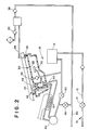
- FIGURE 1 is a perspective view of a sterilizing apparatus in accordance with the present invention;
- FIGURE 2 is a tubing diagram of the sterilizer of FIGURE 1;
- FIGURE 3 is a detailed cross sectional view of the aspirator sterilant withdrawal assembly of FIGURE 1;
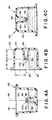
- FIGURE 4A, 4B, and 4C are detailed cross sectional views of the ampule of FIGURE 3 in a range of orientations;
- FIGURES 5A, 5B, 5C, and 5D illustrate a preferred method of loading sterilant and powered reagents into the sterilizing apparatus;
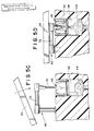
- FIGURE 6 illustrates an alternate embodiment of a sterilant ampule in accordance with the present invention;
- FIGURE 7 is another alternate embodiment of the sterilant ampule;
- FIGURE 8 is a top view of yet another alternate embodiment of the sterilant ampule; and,
- FIGURE 9 illustrates an alternate reagent discharging apparatus.
- With reference to FIGURES 1 and 2, a dilutant or
water source 10 supplies water or other fluid reagents. In the preferred sterilizer embodiment, the water source includes a length oftubing 12 connected with a water spigot or other building plumbing and acontrol valve 14 for selectively preventing and permitting the flow of water to awater sterilizing means 16. In the preferred embodiment, the water sterilizing means is a filter which removes particulates which are as large or larger than bacteria. - A tubing system connects the filter with a container or
module 20 for receiving an item to be sterilized. In the preferred embodiment, the container is defined by aremovable tray 22 configured in accordance with the item to be sterilized, e.g. an endoscope. Alid 24 is sealed to the tray by aresilient gasket 26 to complete the container. Optionally, atransparent window 28 is defined the in the lid. - During a fill cycle, sterile water flows through the tubing system filling itself and the
container 20. The water flows through aspray nozzle 30 and acontainer distribution manifold 32 into the container and a reagent receiving well 34. As more water is introduced,vent lines 36 are filled with excess water and discharged through acheck valve 38 into adrain 40. - A
reagent introduction system 42 selectively supplies sterilant, buffer, detergent, and corrosion inhibitors to the dilutant. More specifically, anaspirator 44 selectively withdraws sterilant concentrate from anampule 46. Powdered reagent received in the well 34 is dissolved as water flows in from the container. - After the system is filled, pump 50 selectively draws water from the
container 20 through the well 34 andaspirator 44. Recirculating the water dissolves the powdered reagents and aspirates the sterilant from the ampule and circulates the sterilant and reagents through thetubing system 18. Preferably, thevent line 36 is very short and of a substantial diameter such that the solution is circulated over exposed services of thedrain check valve 38 and avent check valve 52. Aheating coil 54 adjusts the temperature of the solution. Recirculation continues until the item, the interior of the container, and all exposed surfaces of the tubing system and valves are sterilized. - As the sterilant solution is drained through
drain valve 56, sterile air is drawn into the system through an air sterilizing means - preferably a filter that removes any particles the size of a bacteria or larger. Thefill valve 14 is opened and thedrain valve 56 is closed such that thesterile filter 16 provides a source of sterile rinse. Note that the sterile rinse passes only along sterilized surfaces to assure sterility. Thepump 50 circulates the sterile rinse throughout the system. Sterile rinse is drained by openingdrain valve 56 again. By closing avalve 60, thepump 50 functions to pump liquid from the system out thedrain 40. Additional drain lines (not shown) and aspirators or pumps (not shown) may be provided for removing liquid from all regions of the system. - With particular reference to FIGURE 3, the
sterilant aspirator system 42 includes a hollow, tubular needle ortube 70 which is inserted into the ampule to withdraw the sterilant. Theneedle 70 is connected witharm 72 which selectively swings the needle into and out of alignment with theampule 46. A verticaltubular portion 74 is telescopically received in a stationarytubular portion 86. Acoil spring 78 biases the arm tubular portion upward, hence, theneedle 70 out of contact with the ampule. When the arm is locked into proper alignment with the ampule, closing thelid 24 biases the arm downward against thecoil spring 78 forcing theneedle 70 into the ampule. Water pumped through theaspirator 44 aspirates the sterilant from the ampule into the fluid flow. Preferably, the aspiration rate is selected such that the sterilant is aspirated gradually over the time required to circulate the water around the system one time. - With reference to FIGURES 4A, 4B, and 4C, the
sterilant ampule 46 has anexterior wall 80 which defines aninterior volume 82 therein. Alinear vent passage 84 integral with the exterior wall defines a passage extending linearly from the exterior to avent aperture 86. In the preferred embodiment, the vent passage extends linearly along afirst axis 88 to act as a guide for theneedle 70. In this manner, theneedle 70 passes through thevent aperture 86 into the interior volume. - In the illustrated embodiment, the exterior wall includes a circularly cylindrical peripheral wall 90 a minimum radius r from the first axis.
End walls axis 88 and are integrally sealed to the peripheral wall. Thevent aperture 86 is centrally disposed in the volume. More specifically, thevent aperture 86 is disposed a minimum radial distance r from the peripheral wall and generally a height h from each end wall. The ampule is charged less than half full with afluid sterilant 96 such that itsupper surface 98 is disposed below thevent aperture 86. More specifically, theinterior volume 82 is configured relative to the volume of the sterilant such that the sterilant depth is always less than h and r regardless of the orientation of the ampule. In this manner, the liquid does not leak from thevent aperture 86 regardless of the orientation of theampule 46. - To protect against leakage due to splashing, a
porous membrane 100 is disposed across thevent aperture 86. The membrane is a fine woven material which has a median pore size sufficiently small compared to the drop size and wetting ability or surface tension of the liquid sterilant on the fiber material that the sterilant is effectively blocked from passing therethrough. Similarly, water is prevented from flowing freely into the ampule. When theneedle 70 passes thevent aperture 86, its cambered end distorts the woven porous material moving the fibers out of its way. The natural resiliency of the fibers tends to return them to their original position when the needle is withdrawn. Any sterilant residue is held in the ampule by the position of thevent aperture 86 and themembrane 100. In this manner, after the sterilization cycle is complete, the operator is protected from contacting the full strength sterilant concentrate directly. Analogously, no dilution of the sterilant concentrate occurs if a sterilizing cycle is aborted before aspiration starts. - With reference again to FIGURE 1 and particular reference to FIGURES 5A-D, in operation, the
ampule 46 is disposed in the bottom of a see-throughlarger container 110. Thecontainer 110 has a peel-off top 112 which provides access to its contents. The container is shaped such that theampule 46 fits snugly in the bottom and otherpowdered reagents 114 are disposed on top. - In FIGURE 5B, the
sterilizer arm 72 is swung out of the way and the powdery agents are poured into thewell 34. Theampule 46 is supported by rods or other ampule supporting means 116 in a preselected position in the well. In the illustrated embodiment, the ampule is symmetric, thus assuring a central position of thevent aperture 86. Alternately, the support means 126 may include a key or key means which interacts with a selected portion of the ampule to assure proper alignment and positioning. - In FIGURE 5C, the
aspirator arm 72 is swung and locked until theneedle 70 is directly over thevent aperture 86. Because the ampule is accurately positioned in the well, the aspirator arm is adjusted to lock itself in the aligned position without hand aligning by the operator. When thelid 24 is closed as in FIGURE 5D, the lid cams the aspirator arm against thecoil spring 78 moving the tip of theneedle 70 through the vent aperture into the proper position within the ampule. Optionally, the ampule may have a small well directly in line with the vent to accommodate the tip of the aspirator needle and assure more complete emptying of the ampule. - In the preferred embodiment, the powdered materials include buffers, detergents, and anti-corrosive agents. The anti-corrosive agents are selected in accordance with the selected sterilant and the nature of the materials in the sterilized items, such as brass fittings, that might be subject to corrosion. Further to the preferred embodiment, the sterilant is peracetic acid. Peracetic acid tends to liberate small quantities of oxygen during transportation and storage. Accordingly, the
vent 86 insures that the pressure within the ampule does not become so great that it ruptures. High pressure could also cause spraying of the sterilant upon entry by theneedle 70. Once the peracetic acid is diluted and mixed with the buffers, detergents, and corrosion inhibitors, its efficacy as a sterilant is lost after a relatively short duration. The loss of efficacy is much slower than a normal sterilizing cycle, but too short for an ampule containing all the ingredients to have a satisfactory shelf life. - With reference to FIGURES 6, 7, and 8, the ampule may take various shapes. For example, as shown in FIGURE 6, the
exterior wall 80 may be spherical. The vent aperture is still disposed in the center of the sphere and the fill level is such that the depth of the sterilant is smaller than the radius of the spherical interior volume. Alternately, as illustrated in FIGURE 7, the vent aperture may be disposed eccentrically. However, the vent aperture is still disposed sufficiently close to the center of the interior volume that for the volume of sterilant provided, the upper surface of the sterilant always remains below the vent aperture. As yet another alternative, as shown in FIGURE 8, the ampule may have a groove orkey way 120 in the exterior wall or a groove oraperture 122 in an exterior flange to assure that the ampule is disposed in a preselected alignment. By selecting a sufficiently fanciful or arbitrary exterior shape or key pattern, protection can be had against inserting generally round ampules from other equipment which might contain substances other than sterilants. - With reference to FIGURE 9, the sterilant, buffer, detergent, anti-corrosives, and other reagents may be retrieved from a two compartment container in other ways. For example, the liquid containing
ampule 46 may be mounted in the upper portion of a clearplastic cup 110 with the powdered components orreagents 114 in the lower portion. The powdered components are selected to include a material which changes color upon exposure to the liquid components. In this manner, a visual check is provided that the liquid components have not leaked into the powdered components. Avent 124 in the outer cup provides communication between the ampule and the atmosphere. Rather than siphoning out the liquid sterilant, afirst puncturing ram 130 can extend into the lower part of the cup to introduce water or other dilutant into the cup and dissolve the powdered reagents. Additional water flow into the cup may be had when afirst cutter 132 cuts the cup allowing water pumped into the well to circulate through the powder region of the cup. Movement ofadditional cutters 134 pierce both the cup and the sterilant ampule. In this manner, the powdered ingredients can be dissolved and mixed with recirculating water or other dilutant before the sterilant is released. In the illustrated embodiment,cutters common shaft 136 which is incrementally rotated to cause staged cutting of the cup and the ampule. - The invention has been described with reference to the preferred embodiment. Obviously, modifications and alterations will occur to others upon reading and understanding the preceding detailed description. It is intended that the invention be construed as including all such alterations and modifications insofar as they come within the scope of the appended claims or the equivalents thereof.
Claims (10)
a vent passage defining a vent aperture at one end thereof;
an exterior wall surrounding the vent aperture and defining an interior volume, the exterior wall being sealed to the vent passage.
a source of water;
a container for holding an item to be microbially decontaminated;
a tubing system for providing a fluid flow path for received water from the water source to the container;
a reservoir for receiving powdered reagents including at least one of a buffer, a detergent, and anti-corrosive, and for receiving a vented ampule, the ampule comprising:
a vent passage defining a vent aperture at one end thereof;
an exterior wall surrounding the vent aperture and defining an interior volume which is less than half filled with an antimicrobial solution, the exterior wall being sealed to the vent passage;
the reservoir being connected with the tubing system such that the received water dissolves the powdered reagent; and,
an antimicrobial solution discharging means for selectively discharging the antimicrobial solution from the ampule into the water.
further including a means for supplying a sterile rinse liquid into the tubing system for selectively rinsing antimicrobial solution and powdered reagent residue from the microbially decontaminated item such that microbially decontaminating the tubing system assures that the sterile rinse fluid passes only over microbially decontaminated surfaces as it flows to the container, whereby contamination of the microbially decontaminated item with bacteria from the tubing system is prevented.
Priority Applications (1)
| Application Number | Priority Date | Filing Date | Title |
|---|---|---|---|
| AT89301574T ATE98598T1 (en) | 1988-03-07 | 1989-02-17 | INJECTION DEVICE FOR A CONCENTRATED STERILIZING AGENT. |
Applications Claiming Priority (2)
| Application Number | Priority Date | Filing Date | Title |
|---|---|---|---|
| US07/165,189 US5037623A (en) | 1986-02-06 | 1988-03-07 | Sterilant concentrate injection system |
| US165189 | 1998-10-02 |
Publications (3)
| Publication Number | Publication Date |
|---|---|
| EP0332310A2 true EP0332310A2 (en) | 1989-09-13 |
| EP0332310A3 EP0332310A3 (en) | 1990-11-07 |
| EP0332310B1 EP0332310B1 (en) | 1993-12-15 |
Family
ID=22597841
Family Applications (1)
| Application Number | Title | Priority Date | Filing Date |
|---|---|---|---|
| EP89301574A Expired - Lifetime EP0332310B1 (en) | 1988-03-07 | 1989-02-17 | Sterilant concentrate injection system |
Country Status (8)
| Country | Link |
|---|---|
| US (1) | US5037623A (en) |
| EP (1) | EP0332310B1 (en) |
| JP (1) | JPH01274765A (en) |
| AT (1) | ATE98598T1 (en) |
| CA (1) | CA1320030C (en) |
| DE (1) | DE68911339T2 (en) |
| ES (1) | ES2047109T3 (en) |
| HK (1) | HK183796A (en) |
Cited By (8)
| Publication number | Priority date | Publication date | Assignee | Title |
|---|---|---|---|---|
| EP0395296A2 (en) * | 1989-04-24 | 1990-10-31 | Steris Corporation | Microbial decontamination |
| EP0397352A2 (en) * | 1989-05-09 | 1990-11-14 | Steris Corporation | Microbial decontamination |
| EP0543591A1 (en) * | 1991-11-18 | 1993-05-26 | Steris Corporation | Two compartment cup for powdered sterilant reagent components |
| WO1994026317A1 (en) * | 1993-05-18 | 1994-11-24 | Steris Corporation | Controlled oxygen/anti-microbial release films |
| WO1996000092A1 (en) * | 1994-06-23 | 1996-01-04 | Steris Corporation | Cutter for opening sterilant reagent cups |
| US5723095A (en) * | 1995-12-28 | 1998-03-03 | Steris Corporation | Cleaner concentrate formulation for biological waste fluid handling systems |
| US6379632B1 (en) | 1999-02-05 | 2002-04-30 | Olympus Optical Co., Ltd. | Endoscope cleaning and disinfecting unit |
| US6632397B1 (en) | 1998-10-01 | 2003-10-14 | Minntech Corporation | Multi-part anti-microbial concentrate system, activated solution, use-dilution solution, method of making same, and method of sterilizing with the use-dilution solution |
Families Citing this family (58)
| Publication number | Priority date | Publication date | Assignee | Title |
|---|---|---|---|---|
| US5217698A (en) * | 1986-02-06 | 1993-06-08 | Steris Corporation | Office size instrument sterilization system |
| GB9122048D0 (en) * | 1991-10-17 | 1991-11-27 | Interox Chemicals Ltd | Compositions and uses thereof |
| US5275310A (en) * | 1992-03-13 | 1994-01-04 | American Sterilizer Company | Vented, non-resuable, multi-dose cartridge |
| GB9300366D0 (en) * | 1993-01-09 | 1993-03-03 | Solvay Interox Ltd | Compositions and uses thereof |
| US5465833A (en) * | 1993-04-01 | 1995-11-14 | Tarter; Norman D. | Dental impression material package |
| US5882589A (en) * | 1994-06-03 | 1999-03-16 | Leon Shipper | Sealed endoscope decontamination, disinfection and drying device |
| US5662866A (en) * | 1995-09-25 | 1997-09-02 | Steris Corporation | Two compartment cup for powdered sterilant reagent components |
| US5863498A (en) * | 1997-02-07 | 1999-01-26 | Steris Corporation | Decontamination apparatus door unit |
| US7556767B2 (en) | 1997-12-17 | 2009-07-07 | Ethicon, Inc. | Integrated washing and sterilization process |
| US6203756B1 (en) | 1997-12-17 | 2001-03-20 | Johnson & Johnson Medical, Inc. | Integrated cleaning sterilization process |
| US7229591B2 (en) * | 1997-08-21 | 2007-06-12 | Ethicon, Inc. | Lumen sterilization device and method |
| US5863499A (en) * | 1997-11-03 | 1999-01-26 | Steris Corporation | Light weight vented package for liquids |
| DE69821973T2 (en) | 1997-12-04 | 2004-11-11 | Steris Corp., Mentor | CHEMICAL CHANGE OF ELECTROCHEMICALLY ACTIVATED WATER |
| US6645430B1 (en) | 1997-12-17 | 2003-11-11 | Ethicon, Inc. | Method and apparatus for processing device with fluid submersion |
| US6596232B1 (en) | 1997-12-17 | 2003-07-22 | Ethicon, Inc. | Device processing apparatus and method having positive pressure with two partitions to minimize leakage |
| US6013227A (en) * | 1997-12-17 | 2000-01-11 | Johnson & Johnson Medical, Inc. | Lumen device reprocessor without occlusion |
| US6187266B1 (en) | 1997-12-17 | 2001-02-13 | Johnson & Johnson Medical, Inc. | Integrated cleaning/sterilization process with lumen devices |
| US6083458A (en) * | 1997-12-17 | 2000-07-04 | Ethicon, Inc. | Apparatus and method for providing fluid to devices with reduced or without occlusion |
| US6685895B1 (en) | 1997-12-17 | 2004-02-03 | Ethicon, Inc. | Method and apparatus for processing device with reduced occlusion |
| US6015529A (en) * | 1997-12-17 | 2000-01-18 | Johnson & Johnson Medical, Inc. | Tray/container system for cleaning/sterilization processes |
| CN1248741C (en) * | 1997-12-23 | 2006-04-05 | 斯特里斯公司 | Antimicrobial compsn. Delivery system with integrated filter |
| US6103189A (en) * | 1998-03-10 | 2000-08-15 | Kralovic; Raymond C. | Method of removing microbial contamination |
| US6361552B1 (en) * | 1998-03-25 | 2002-03-26 | Michael J. Badalamenti | Teething gel applicator with cutter, and burstable ampule and method of making the same |
| US6364103B1 (en) | 1998-10-22 | 2002-04-02 | Sermed Industries, Inc. | Cartridge for holding a first and second fluid |
| US6521180B2 (en) | 1998-10-22 | 2003-02-18 | Sermed Industries, Inc. | Method of sterilization |
| AU1320000A (en) | 1998-10-22 | 2000-05-08 | Sermed Industries Inc. | An apparatus and method for sterilizing an instrument at substantially room temperature |
| US6092649A (en) * | 1998-10-22 | 2000-07-25 | Sermed Industries Inc. | Cartridge for holding a first and second fluid |
| WO2000026334A1 (en) * | 1998-10-30 | 2000-05-11 | Metrex Research Corporation | Simultaneous cleaning and decontaminating compositions and methods |
| US6203767B1 (en) | 1998-11-06 | 2001-03-20 | Steris Corporation | Peracetic acid card reader and card style sensor |
| WO2000030690A1 (en) | 1998-11-23 | 2000-06-02 | Ecolab Inc. | Non-corrosive sterilant composition |
| US6312645B1 (en) | 1998-12-30 | 2001-11-06 | Ethicon, Inc. | Container with collapsible pouch for cleaning or sterilization |
| US6534002B1 (en) | 1998-12-30 | 2003-03-18 | Ethicon, Inc. | Flow of fluid through a lumen device from smaller-caliber end to larger-caliber end |
| ES2301258T3 (en) | 1998-12-30 | 2008-06-16 | Ethicon, Inc. | STERILE PACKING FOR FLEXIBLE ENDOSCOPES. |
| US6749807B1 (en) * | 1999-05-19 | 2004-06-15 | Steris Corporation | Flow through chemical indicator for measurement of active biocidal agents in a single use package |
| US6527872B1 (en) | 1999-07-28 | 2003-03-04 | Steris Inc. | Environmentally friendly peracetic acid decontamination formula with increased performance and chemical stability |
| US6485979B1 (en) * | 1999-08-05 | 2002-11-26 | 3M Innovative Properties Company | Electronic system for tracking and monitoring articles to be sterilized and associated method |
| US6482358B1 (en) | 2000-02-07 | 2002-11-19 | Steris Inc. | Three part cup for packaging cleaning and sterilizing agents and sequential cutter |
| US6585943B1 (en) | 2000-02-07 | 2003-07-01 | Steris Inc. | Liquid cleaning and sterilization system |
| US20050126984A1 (en) * | 2001-09-10 | 2005-06-16 | The Procter & Gamble Company | Consumable container comprising a filter |
| MXPA04002252A (en) * | 2001-09-10 | 2004-06-29 | Procter & Gamble | Consumable container comprising a filter. |
| US7351386B2 (en) | 2002-04-04 | 2008-04-01 | Steris Inc | Cartridge holder for automated reprocessor |
| US6979428B2 (en) * | 2003-08-01 | 2005-12-27 | Steris Inc. | Fluid over-flow/make-up air assembly for reprocessor |
| US20050220665A1 (en) * | 2004-04-05 | 2005-10-06 | Ding Lambert L | Low temperature sterilization and disinfections method and apparatus for medical apparatus and instruments |
| US20050226795A1 (en) * | 2004-04-05 | 2005-10-13 | Steriquip, Inc. | Durable fill block for flow of fluids through a hinged lid |
| US7998751B2 (en) * | 2005-04-26 | 2011-08-16 | Siemens Healthcare Diagnostics Inc. | Method and apparatus for aspirating and dispensing small liquid samples in an automated clinical analyzer |
| AU2006278364B2 (en) | 2005-08-05 | 2012-04-19 | Hemostasis, Llc | Antimicrobial composition and system |
| WO2008109253A1 (en) | 2007-03-06 | 2008-09-12 | Steris Inc. | Transportable decontamination unit and decontamination process |
| AR078060A1 (en) * | 2009-07-14 | 2011-10-12 | Novartis Ag | DECONTAMINATION OF CONTAINER SURFACE PREVIOUSLY FILLED IN SECONDARY PACKAGING |
| CA2808561C (en) * | 2009-09-30 | 2017-08-29 | Tso3 Inc. | Sterilization apparatus |
| US8668880B2 (en) | 2010-03-31 | 2014-03-11 | American Sterilizer Company | Apparatus for releasing a dry chemistry into a liquid sterilization system |
| US20130233736A1 (en) * | 2012-03-09 | 2013-09-12 | Invivo Therapeutics Corporation | Protective packaging with product preparation features incorporated |
| JP5943102B2 (en) * | 2012-12-13 | 2016-06-29 | キヤノンマーケティングジャパン株式会社 | Sterilizer, sterilization method, program |
| JP5696740B2 (en) * | 2012-12-13 | 2015-04-08 | キヤノンマーケティングジャパン株式会社 | Sterilizer, sterilization method, program |
| US10022189B2 (en) | 2013-12-16 | 2018-07-17 | Stryker Sustainability Solutions, Inc. | Apparatus and method for cleaning an instrument |
| US10183087B2 (en) | 2015-11-10 | 2019-01-22 | American Sterilizer Company | Cleaning and disinfecting composition |
| KR101924992B1 (en) * | 2016-10-25 | 2018-12-04 | 주식회사 플라즈맵 | Sterilization Apparatus And Sterilization Method |
| US11123695B2 (en) | 2017-07-17 | 2021-09-21 | American Sterilizer Company | Container for hydrogen peroxide solutions |
| JPWO2021241098A1 (en) * | 2020-05-28 | 2021-12-02 |
Citations (3)
| Publication number | Priority date | Publication date | Assignee | Title |
|---|---|---|---|---|
| FR547150A (en) * | 1922-02-13 | 1922-12-01 | Device for storing volatile disinfectant liquids | |
| DE1216770B (en) * | 1963-07-26 | 1966-05-12 | Hans Dohse | Airtight container and device for evacuating and airtight closing this container |
| FR2138154A3 (en) * | 1971-05-19 | 1972-12-29 | Benz Otto |
Family Cites Families (22)
| Publication number | Priority date | Publication date | Assignee | Title |
|---|---|---|---|---|
| DE88419C (en) * | ||||
| US675971A (en) * | 1901-01-07 | 1901-06-11 | Carter S Ink Co | Paste pot or jar. |
| US854617A (en) * | 1906-07-03 | 1907-05-21 | Scient Preservation Company | Gas-generator for fumigation. |
| US2494456A (en) * | 1946-03-18 | 1950-01-10 | Kathleen S Still | Container |
| CH308716A (en) * | 1952-12-24 | 1955-07-31 | Cableries Et Trefileries Sa De | Box. |
| FR1304099A (en) * | 1961-08-07 | 1962-09-21 | Parisienne De Marques Et Breve | Measuring cup |
| GB1180059A (en) * | 1967-12-08 | 1970-02-04 | Waddington Ltd J | Improvements in or relating to Containers Adapted for Packaging Two or More Substances. |
| US3521745A (en) * | 1968-07-31 | 1970-07-28 | Gilbert Schwartzman | Mixing package |
| US3713780A (en) * | 1971-02-01 | 1973-01-30 | Becton Dickinson Co | Apparatus for chemical testing |
| JPS5019344U (en) * | 1973-06-15 | 1975-03-04 | ||
| US3893832A (en) * | 1973-11-01 | 1975-07-08 | Mead Corp | Sterile fluid system |
| US4171340A (en) * | 1977-03-03 | 1979-10-16 | Earth Chemical Company, Ltd. | Fumigating apparatus and method |
| DE2749448A1 (en) * | 1977-11-04 | 1979-05-10 | Stierlen Maquet Ag | Cleaning combined with disinfection - in four chambers with disinfectant added to cleansing agent |
| JPS55139596A (en) * | 1979-04-18 | 1980-10-31 | Tlv Co Ltd | Bucket float type steam trap |
| JPS6120142Y2 (en) * | 1980-07-01 | 1986-06-17 | ||
| US4362241A (en) * | 1980-08-06 | 1982-12-07 | Williams Robert M | Apparatus for cold disinfection of dental and medical instruments |
| DE3109921A1 (en) * | 1981-03-14 | 1982-09-23 | Wella Ag, 6100 Darmstadt | TWO-COMPONENT PACKAGING FOR SCHUETTABLE MEDIA |
| US4552728A (en) * | 1981-05-11 | 1985-11-12 | Hal Johnston Pty. Limited | Decontamination apparatus |
| CH663186A5 (en) * | 1982-06-04 | 1987-11-30 | Nestle Sa | COMPOSITE CONTAINER. |
| DE3303838A1 (en) * | 1983-02-04 | 1984-08-09 | Mühlbauer, Ernst, Dipl.-Kaufm., 2000 Hamburg | MULTI-COMPONENT CAPSULE |
| DE3339930A1 (en) * | 1983-11-04 | 1985-05-23 | Hamba-Maschinenfabrik Hans A.Müller GmbH & Co KG, 5600 Wuppertal | Method and device for sterilization of cup-shaped containers intended for accommodation of dairy products |
| US4794085A (en) * | 1984-07-19 | 1988-12-27 | Eastman Kodak Company | Apparatus and method for detecting liquid penetration by a container used for aspirating and dispensing the liquid |
-
1988
- 1988-03-07 US US07/165,189 patent/US5037623A/en not_active Expired - Lifetime
-
1989
- 1989-01-30 CA CA000589566A patent/CA1320030C/en not_active Expired - Lifetime
- 1989-02-17 AT AT89301574T patent/ATE98598T1/en not_active IP Right Cessation
- 1989-02-17 DE DE89301574T patent/DE68911339T2/en not_active Expired - Lifetime
- 1989-02-17 ES ES89301574T patent/ES2047109T3/en not_active Expired - Lifetime
- 1989-02-17 EP EP89301574A patent/EP0332310B1/en not_active Expired - Lifetime
- 1989-03-07 JP JP1054853A patent/JPH01274765A/en active Granted
-
1996
- 1996-10-03 HK HK183796A patent/HK183796A/en not_active IP Right Cessation
Patent Citations (3)
| Publication number | Priority date | Publication date | Assignee | Title |
|---|---|---|---|---|
| FR547150A (en) * | 1922-02-13 | 1922-12-01 | Device for storing volatile disinfectant liquids | |
| DE1216770B (en) * | 1963-07-26 | 1966-05-12 | Hans Dohse | Airtight container and device for evacuating and airtight closing this container |
| FR2138154A3 (en) * | 1971-05-19 | 1972-12-29 | Benz Otto |
Cited By (12)
| Publication number | Priority date | Publication date | Assignee | Title |
|---|---|---|---|---|
| US5116575A (en) * | 1986-02-06 | 1992-05-26 | Steris Corporation | Powdered anti-microbial composition |
| US5407685A (en) * | 1986-02-06 | 1995-04-18 | Steris Corporation | Controlled oxygen/anti-microbial release films |
| EP0395296A2 (en) * | 1989-04-24 | 1990-10-31 | Steris Corporation | Microbial decontamination |
| EP0395296A3 (en) * | 1989-04-24 | 1991-09-11 | Steris Corporation | Microbial decontamination |
| EP0397352A2 (en) * | 1989-05-09 | 1990-11-14 | Steris Corporation | Microbial decontamination |
| EP0397352A3 (en) * | 1989-05-09 | 1991-09-11 | Steris Corporation | Microbial decontamination |
| EP0543591A1 (en) * | 1991-11-18 | 1993-05-26 | Steris Corporation | Two compartment cup for powdered sterilant reagent components |
| WO1994026317A1 (en) * | 1993-05-18 | 1994-11-24 | Steris Corporation | Controlled oxygen/anti-microbial release films |
| WO1996000092A1 (en) * | 1994-06-23 | 1996-01-04 | Steris Corporation | Cutter for opening sterilant reagent cups |
| US5723095A (en) * | 1995-12-28 | 1998-03-03 | Steris Corporation | Cleaner concentrate formulation for biological waste fluid handling systems |
| US6632397B1 (en) | 1998-10-01 | 2003-10-14 | Minntech Corporation | Multi-part anti-microbial concentrate system, activated solution, use-dilution solution, method of making same, and method of sterilizing with the use-dilution solution |
| US6379632B1 (en) | 1999-02-05 | 2002-04-30 | Olympus Optical Co., Ltd. | Endoscope cleaning and disinfecting unit |
Also Published As
| Publication number | Publication date |
|---|---|
| JPH0568990B2 (en) | 1993-09-30 |
| US5037623A (en) | 1991-08-06 |
| ES2047109T3 (en) | 1994-02-16 |
| EP0332310B1 (en) | 1993-12-15 |
| CA1320030C (en) | 1993-07-13 |
| JPH01274765A (en) | 1989-11-02 |
| EP0332310A3 (en) | 1990-11-07 |
| HK183796A (en) | 1996-10-11 |
| DE68911339T2 (en) | 1994-04-07 |
| DE68911339D1 (en) | 1994-01-27 |
| ATE98598T1 (en) | 1994-01-15 |
Similar Documents
| Publication | Publication Date | Title |
|---|---|---|
| EP0332310B1 (en) | Sterilant concentrate injection system | |
| AU657177B2 (en) | Two compartment cup for powdered sterilant reagent components | |
| US5833935A (en) | Microbial decontamination system with components porous to anti-microbial fluids | |
| US5091343A (en) | Container for holding equipment during sterilization | |
| EP0507461B1 (en) | Office size instrument sterilization system | |
| EP0862465B1 (en) | Two compartment cup for powdered sterilant reagent components | |
| CA2197646C (en) | Container with internal liquid distribution port for holding equipment with internal passages during sterilization | |
| US7351386B2 (en) | Cartridge holder for automated reprocessor | |
| US5439654A (en) | Cutter for opening sterilant reagent cups | |
| AU738373B2 (en) | Multi-compartment plastic woven mesh dry chemistry container | |
| US6482358B1 (en) | Three part cup for packaging cleaning and sterilizing agents and sequential cutter | |
| CA1321137C (en) | Anti-microbial composition | |
| MXPA97001643A (en) | Container with internal door distributing liquid, to retain a team with internal passages, during the sterilization | |
| US5863499A (en) | Light weight vented package for liquids | |
| CA2012862C (en) | Container for holding equipment during sterilization |
Legal Events
| Date | Code | Title | Description |
|---|---|---|---|
| PUAI | Public reference made under article 153(3) epc to a published international application that has entered the european phase |
Free format text: ORIGINAL CODE: 0009012 |
|
| AK | Designated contracting states |
Kind code of ref document: A2 Designated state(s): AT BE CH DE ES FR GB GR IT LI LU NL SE |
|
| RIN1 | Information on inventor provided before grant (corrected) |
Inventor name: KRALOVIC, RAYMOND C. Inventor name: SIEGEL, NORMAN L. Inventor name: SCHNEIDER, EDWARD T. |
|
| 17P | Request for examination filed |
Effective date: 19900711 |
|
| PUAL | Search report despatched |
Free format text: ORIGINAL CODE: 0009013 |
|
| AK | Designated contracting states |
Kind code of ref document: A3 Designated state(s): AT BE CH DE ES FR GB GR IT LI LU NL SE |
|
| 17Q | First examination report despatched |
Effective date: 19920623 |
|
| RAP1 | Party data changed (applicant data changed or rights of an application transferred) |
Owner name: STERIS CORPORATION |
|
| GRAA | (expected) grant |
Free format text: ORIGINAL CODE: 0009210 |
|
| STAA | Information on the status of an ep patent application or granted ep patent |
Free format text: STATUS: THE PATENT HAS BEEN GRANTED |
|
| AK | Designated contracting states |
Kind code of ref document: B1 Designated state(s): AT BE CH DE ES FR GB GR IT LI LU NL SE |
|
| REF | Corresponds to: |
Ref document number: 98598 Country of ref document: AT Date of ref document: 19940115 Kind code of ref document: T |
|
| REF | Corresponds to: |
Ref document number: 68911339 Country of ref document: DE Date of ref document: 19940127 |
|
| REG | Reference to a national code |
Ref country code: ES Ref legal event code: FG2A Ref document number: 2047109 Country of ref document: ES Kind code of ref document: T3 |
|
| ET | Fr: translation filed | ||
| ITF | It: translation for a ep patent filed |
Owner name: ING. C. GREGORJ S.P.A. |
|
| REG | Reference to a national code |
Ref country code: GR Ref legal event code: FG4A Free format text: 3010937 |
|
| EPTA | Lu: last paid annual fee | ||
| PLBE | No opposition filed within time limit |
Free format text: ORIGINAL CODE: 0009261 |
|
| 26N | No opposition filed | ||
| EAL | Se: european patent in force in sweden |
Ref document number: 89301574.3 |
|
| REG | Reference to a national code |
Ref country code: GB Ref legal event code: IF02 |
|
| REG | Reference to a national code |
Ref country code: CH Ref legal event code: PFA Owner name: STERIS CORPORATION Free format text: STERIS CORPORATION#9450 PINENEEDLE DRIVE#MENTOR/OH (US) -TRANSFER TO- STERIS CORPORATION#9450 PINENEEDLE DRIVE#MENTOR/OH (US) |
|
| PGFP | Annual fee paid to national office [announced via postgrant information from national office to epo] |
Ref country code: ES Payment date: 20080226 Year of fee payment: 20 Ref country code: CH Payment date: 20080228 Year of fee payment: 20 |
|
| PGFP | Annual fee paid to national office [announced via postgrant information from national office to epo] |
Ref country code: SE Payment date: 20080227 Year of fee payment: 20 Ref country code: LU Payment date: 20080307 Year of fee payment: 20 Ref country code: NL Payment date: 20080224 Year of fee payment: 20 Ref country code: GB Payment date: 20080227 Year of fee payment: 20 Ref country code: IT Payment date: 20080228 Year of fee payment: 20 |
|
| PGFP | Annual fee paid to national office [announced via postgrant information from national office to epo] |
Ref country code: AT Payment date: 20080201 Year of fee payment: 20 |
|
| PGFP | Annual fee paid to national office [announced via postgrant information from national office to epo] |
Ref country code: DE Payment date: 20080331 Year of fee payment: 20 Ref country code: FR Payment date: 20080218 Year of fee payment: 20 |
|
| PGFP | Annual fee paid to national office [announced via postgrant information from national office to epo] |
Ref country code: BE Payment date: 20080306 Year of fee payment: 20 |
|
| PGFP | Annual fee paid to national office [announced via postgrant information from national office to epo] |
Ref country code: GR Payment date: 20080228 Year of fee payment: 20 |
|
| REG | Reference to a national code |
Ref country code: CH Ref legal event code: PL |
|
| REG | Reference to a national code |
Ref country code: GB Ref legal event code: PE20 Expiry date: 20090216 |
|
| EUG | Se: european patent has lapsed | ||
| REG | Reference to a national code |
Ref country code: ES Ref legal event code: FD2A Effective date: 20090218 |
|
| NLV7 | Nl: ceased due to reaching the maximum lifetime of a patent |
Effective date: 20090217 |
|
| PG25 | Lapsed in a contracting state [announced via postgrant information from national office to epo] |
Ref country code: NL Free format text: LAPSE BECAUSE OF EXPIRATION OF PROTECTION Effective date: 20090217 |
|
| PG25 | Lapsed in a contracting state [announced via postgrant information from national office to epo] |
Ref country code: GB Free format text: LAPSE BECAUSE OF EXPIRATION OF PROTECTION Effective date: 20090216 |
|
| PG25 | Lapsed in a contracting state [announced via postgrant information from national office to epo] |
Ref country code: ES Free format text: LAPSE BECAUSE OF EXPIRATION OF PROTECTION Effective date: 20090218 |