EP0400249A1 - Apparatus for perforating a web - Google Patents
Apparatus for perforating a web Download PDFInfo
- Publication number
- EP0400249A1 EP0400249A1 EP19890420086 EP89420086A EP0400249A1 EP 0400249 A1 EP0400249 A1 EP 0400249A1 EP 19890420086 EP19890420086 EP 19890420086 EP 89420086 A EP89420086 A EP 89420086A EP 0400249 A1 EP0400249 A1 EP 0400249A1
- Authority
- EP
- European Patent Office
- Prior art keywords
- sheet
- injector
- water
- cylinder
- plate
- Prior art date
- Legal status (The legal status is an assumption and is not a legal conclusion. Google has not performed a legal analysis and makes no representation as to the accuracy of the status listed.)
- Granted
Links
Images
Classifications
-
- D—TEXTILES; PAPER
- D04—BRAIDING; LACE-MAKING; KNITTING; TRIMMINGS; NON-WOVEN FABRICS
- D04H—MAKING TEXTILE FABRICS, e.g. FROM FIBRES OR FILAMENTARY MATERIAL; FABRICS MADE BY SUCH PROCESSES OR APPARATUS, e.g. FELTS, NON-WOVEN FABRICS; COTTON-WOOL; WADDING ; NON-WOVEN FABRICS FROM STAPLE FIBRES, FILAMENTS OR YARNS, BONDED WITH AT LEAST ONE WEB-LIKE MATERIAL DURING THEIR CONSOLIDATION
- D04H18/00—Needling machines
- D04H18/04—Needling machines with water jets
-
- B—PERFORMING OPERATIONS; TRANSPORTING
- B26—HAND CUTTING TOOLS; CUTTING; SEVERING
- B26F—PERFORATING; PUNCHING; CUTTING-OUT; STAMPING-OUT; SEVERING BY MEANS OTHER THAN CUTTING
- B26F1/00—Perforating; Punching; Cutting-out; Stamping-out; Apparatus therefor
- B26F1/26—Perforating by non-mechanical means, e.g. by fluid jet
Definitions
- the present invention relates to a universal method for manufacturing a sheet which is completely or incompletely perforated, that is to say in particular a sheet pierced with multiple perforations, or else a sheet having, at the end of the operation, a design with intaglio or relief patterns.
- this new process can be used on a sheet of any material, which can be, in particular, a paper, a cardboard, a nonwoven fabric, a film, or a plastic plate, or even a sheet of wood or plywood.
- the invention also relates to new industrial products obtained according to this method, and having original characteristics which it is not possible to obtain with known traditional methods.
- the object of the present invention is to avoid these drawbacks by providing a practically universal machine for the production of papers, non-woven fabrics, textiles or plastic films which are perforated or have intaglio or raised patterns.
- a device comprises a support fabric for the sheet material to be treated to be treated which advances with the material under a rotating perforated cylinder, inside which is arranged a fixed water injector oriented transversely to project pressurized water through the perforations of the cylinder in the direction of the sheet to be treated, and it is characterized in that the hydraulic injector comprises, on the one hand a high pressure water inlet chamber which discharges the water against a perforated plate whose holes define needles of water then directed opposite cylinder holes, on the other hand, under the sheet to be treated, a suction box for the water having passed through said sheet.
- the needles are arranged opposite the holes of the cylinder, offset along one or more generatrices thereof, so as to be the most spaced from each other, on the one hand, to avoid , as much as possible, parasitic phenomena due to the reflection of water on the solid parts of the cylinder, on the other hand, to limit the water flow.
- the diameter of the holes in the perforated plate is between 50 and 500 microns.
- a perforated plate pierced with holes arranged according to several distinct generatrices the holes in the plate being always located opposite those of the cylinder, so that the water emitted by the injector completely covers the width of the holes in the cylinder.
- the injector comprises a device for holding the perforated plate, making it easy to remove it from the body of the injector: the perforated plate is applied strongly against the main body of the injector thanks to the action of hydraulic cylinders which pull the plate upwards via a set of lifting beams and tie rods arranged along the injector.
- a seal located between the perforated plate and the main injector body makes it possible to seal the assembly. It suffices to release the oil pressure in the hydraulic cylinders, to release the clamping jaws of the perforated plate which it is then possible to extract very easily, by pulling it in the longitudinal direction of the injector, c ' that is to say transversely to the direction of advancement of the sheet material.
- the water pressure in the main body of the injector is between 2 and 500 bars depending on whether the material to be treated is more or less thick and must be perforated, or simply marked with a water jet.
- the perforated cylinder can be in contact with the sheet to be treated or be detached from it so that its speed of rotation can be independent of the speed of movement of the sheet, the rotation being able to possibly take place in the opposite direction to that of the sheet scrolling.
- the perforated cylinder can be of any type, stainless steel, bronze, or even nickel. This list is not exhaustive: it can also be of the same type, for example, as the well-known screen printing cylinders used in textile printing or the deposits of plastic material in relief on floor coverings: the only limit is its mechanical resistance nique to the action of the needles of water emitted by the hydraulic injector.
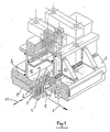
- FIG. 1 shows a sheet 1, for example of a nonwoven fabric, which advances in the longitudinal direction represented by the arrow 2.
- the fixed elongated body 3 of an injector in which a water chamber 4 is defined.
- the lower bottom thereof is constituted by a plate 5, on which micro-perforations 6 are made, which will each define a water needle 7.
- Two longitudinal jaws 8 and 9 are subjected to the action of hydraulic cylinders such as 10, to clamp and tighten the longitudinal edges (perpendicular to the arrow 2), of the plate 5 against the body 3 of the injector. the sealing of the mounting of the plate 5 against the injector body 3, when the assembly is in service.
- This water chamber 4 is, for example, surmounted by a water supply chamber 12, with which it comlunique by large holes 13.
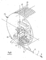
- the hydraulic injector 3 - 5 - 8 - 9 is mounted in a fixed position inside a rotary cylinder 14, on the thin wall 15 of which are distributed orifices 16.
- the wall 15 of the cylinder 14 can be at a certain distance 17 above the upper face of the sheet 1.
- the tangential speed of the rotary cylinder 14 (arrow 18) is independent of the speed of advance of the sheet 1 (arrow 2).
- An 18 g / m2 non-woven sheet obtained by the so-called "wet process” is supported by a bronze fabric of knitting type, comprising 32 threads in the warp direction, and 27 threads in the weft direction. This sheet is subjected to the action of the device shown in Figures 2 and 3.
- the perforated cylinder 14 has holes 16 of rectangular section 0.8 mm in the axial direction (arrow 19) and 1.3 mm in the tangential direction (arrow 20), the distance between these holes being 0.8 mm in both directions.
- the thickness of the cylinder is 0.4 mm and the section of the holes is identical inside and outside the cylinder.
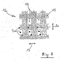
- the hydraulic injector comprises a perforated plate 0.3 mm thick comprising three rows of holes 0.28 mm in diameter spaced 1.6 mm (from axis to axis) along a generator, and 1 mm between the generators (see Figure 3).
- the water pressure in the injector is 3.5 bars (chambers 4 and 12).
- the cylinder is held at 0.5 mm above the sheet 1 and its tangential speed of rotation (arrow 18) is equal to the speed of advancement of the sheet 1 (arrow 2).
- a plastic sheet 30 microns thick is subjected to the action of the above device.
- Sheet 1 is placed on a stainless steel support fabric of the "plain" type, comprising 7 threads per cm, in the warp and weft directions.
- the perforated plate 5 of the injector has a single row of holes 6, 0.12 mm in diameter, spaced from each other by 1.6 mm.
- the perforated plate 5 is positioned so that the water needles 7 are located approximately in the middle of the orifices 16 of the perforated cylinder 14.
- the water pressure in the injector is 150 bars and the treatment speed 25 meters / min.
- the cylinder is located 1 mm above the fabric (interval 17), and its tangential speed of rotation (arrow 18) is equal to the speed of advance of the sheet 1 and its fabric (arrow 2).
- the plastic sheet 1 is perforated in the form of thin rectangular slots, 0.8 mm in length and non-measurable width.
- the resistance in the transverse direction of the sheet 1 is considerably reduced, and its porosity is greatly increased.
- the sheet 1 subjected to a jet of water is no longer waterproof.
- the same sheet 1 is subjected to a similar treatment.
- the only difference with the previous treatment is the speed of rotation of the cylinder 14 which gives a vi tangential tesse (arrow 18) of 120 meters per minute (about five times the speed of advancement of sheet 1 (arrow 2).
- the plastic sheet 1 is now punctured by a multitude of small holes whose dimensions are not measurable.
- the air permeability of the sheet is excellent, and its transverse resistance is little affected.
- the sheet subjected to a jet of water also remains waterproof. Finally, the plastic film has lost its characteristic "sound".
Abstract
Description
La présente invention concerne un procédé universel , pour fabriquer une feuille qui soit complètement ou incomplètement perforée , c'est-à-dire notamment une feuille percée de perforations multiples , ou bien une feuille présentant , en fin d'opération , un dessin avec des motifs en creux ou en relief .The present invention relates to a universal method for manufacturing a sheet which is completely or incompletely perforated, that is to say in particular a sheet pierced with multiple perforations, or else a sheet having, at the end of the operation, a design with intaglio or relief patterns.
Il est bien entendu que ce procédé nouveau peut être utilisé sur une feuille d'un matériau quelconque , qui peut être , en particulier , un papier , un carton ,un tissu non tissé , un film , ou une plaque de matière plastique , voire une feuille de bois ou de contre-plaqué.It is understood that this new process can be used on a sheet of any material, which can be, in particular, a paper, a cardboard, a nonwoven fabric, a film, or a plastic plate, or even a sheet of wood or plywood.
L'invention concerne également les produits industriels nouveaux obtenus suivant cette méthode , et possédant des caractéristiques originales qu'il n'est pas possible d'obtenir avec les méthodes traditionnelles connues.The invention also relates to new industrial products obtained according to this method, and having original characteristics which it is not possible to obtain with known traditional methods.
Il est connu de fabriquer des étoffes non-tissées ,présentant des perforations ou possédant des zones de fibres de densité réduite , notamment pour des applications dans des domaines médicaux ou hospitaliers , de l'essuyage , de la filtration , d'enveloppes pour sachets de thé etc.. . Pour cela , il est connu , par exemple dans le brevet français 2 068 676 , de faire circuler une nappe de fibres sur la toile poreuse d'un support transporteur , la nappe à traiter passant sous un cylindre rotatif perforé à l'intérieur duquel est disposé un injecteur hydraulique , qui se présente sous la forme d'une barre transversale fixe . Cet injecteur projette sous pression un rideau d'eau continu ,dont une partie traverse les trous du cylindre perforé , créant ainsi des jets d'eau dont la dimension correspond à celle des perforations du cylindre . Ces jets d'eau traversent la nappe de fibres en reproduisant sur celle -ci la forme des trous du cylindre avant d' être recueillie par une caisse aspirante située sous la toile du transporteur , au-dessous du cylindre rotatif.It is known to manufacture nonwoven fabrics, having perforations or having areas of fibers of reduced density, in particular for applications in medical or hospital fields, wiping, filtration, envelopes for sachets of tea etc ... For this, it is known, for example in French patent 2,068,676, to circulate a sheet of fibers on the porous fabric of a carrier support, the sheet to be treated passing under a rotary perforated cylinder inside which is arranged a hydraulic injector, which is in the form of a fixed crossbar. This injector projects under pressure a continuous curtain of water, part of which passes through the holes of the perforated cylinder, thus creating water jets whose size corresponds to that of the perforations in the cylinder. These water jets pass through the sheet of fibers, reproducing on the latter the shape of the holes in the cylinder before being collected by a suction box located under the fabric of the conveyor, below the rotary cylinder.
Un tel dispositif connu présente de grands désavantages . En effet , l'utilisation d'un injecteur fournissant une lame d'eau continue sur toute la géné ratrice du cylindre se traduit par la délivrance d'un débit d'eau considérable à l'intérieur de celui-ci .Compte tenu du fait que les parties perforées du cylindre ne représentent qu'une faible partie de la surface de celui-ci , il en résulte que l'on est rapidement confronté à un problème pratiquement insoluble , qui est celui de l'élimination , à l'intérieur du cylindre , de l'eau réfléchie par les parties pleines.Such a known device has great disadvantages. Indeed, the use of an injector providing a continuous blade of water over the whole gen Ratrice of the cylinder results in the delivery of a considerable flow of water inside it. Given the fact that the perforated parts of the cylinder represent only a small part of the surface thereof, as a result, one is rapidly confronted with a practically insoluble problem, which is that of the elimination, inside the cylinder, of the water reflected by the solid parts.
Afin de limiter le problème , on est conduit à diminuer la quantité d'eau émise par l'injecteur , c'est-à-dire à réduire l'épaisseur du rideau d'eau, ainsi que la pression de l'eau , ce qui a pour conséquence l'obtention , à l'extérieur du cylindre ,de jets d'eau qui ne possèdent pas une énergie cinétique suffisante : pour perforer des matériaux du type film plastique , tissus, voire papier épais.In order to limit the problem, it is necessary to reduce the amount of water emitted by the injector, that is to say to reduce the thickness of the water curtain, as well as the water pressure, this which results in the obtaining, outside of the cylinder, of water jets which do not have sufficient kinetic energy: to perforate materials of the plastic film, tissue, or even thick paper type.
L'eau qui rebondit sur les parties pleines du cylindre le long de la même génératrice perturbe également la cohésion du rideau d'eau et affecte considérablement l'énergie cinétique des jets d'eau émis par le cylindre . En effet , l'eau a tendance à retomber de façon aléatoire dans le cylindre après rebondissement . Cela se traduit par une accumulation anarchique d'eau le long de la génératrice du cylindre située au droit du rideau d' eau .The water which rebounds on the solid parts of the cylinder along the same generator also disturbs the cohesion of the curtain of water and considerably affects the kinetic energy of the water jets emitted by the cylinder. Indeed, water tends to fall randomly into the cylinder after rebounding. This results in an uncontrolled accumulation of water along the generator of the cylinder located to the right of the water curtain.
Cette eau en excès joue le rôle d' amortisseur envers l'eau émise par l'injecteur qui voit ainsi son énergie cinétique réduite à un niveau tel qu'elle devient insuffisante pour assurer un marquage uniforme de la feuille à cet endroit . . Il en résulte , sur la feuille à traiter , l'apparition de zones présentant un aspect délavé dont le dessin ou la perforation sont mal définis.This excess water acts as a shock absorber against the water emitted by the injector which thus sees its kinetic energy reduced to a level such that it becomes insufficient to ensure uniform marking of the sheet at this location. . As a result, on the sheet to be treated, the appearance of areas having a washed out appearance whose design or perforation are poorly defined.
La présente invention a pour but d'éviter ces inconvénients ,en réalisant une machine pratiquement universelle pour la fabrication de papiers , d' étoffes non-tissées , de textiles ou de films plastiques perforés ou possédant des motifs en creux ou en relief.The object of the present invention is to avoid these drawbacks by providing a practically universal machine for the production of papers, non-woven fabrics, textiles or plastic films which are perforated or have intaglio or raised patterns.
Un dispositif suivant l'invention comprend une toile de support pour le matériau en feuille à traiter à traiter qui avance avec le matériau sous un cylindre perforé tournant , à l'intérieur duquel est disposé un injecteur d'eau fixe orienté transversalement pour projeter de l'eau sous pression à travers les perforations du cylindre en direction de la feuille à traiter , et il est caractérisé en ce que l'injecteur hydraulique comporte , d'une part une chambre d'arrivée d'eau à haute pression qui refoule l'eau contre une plaque perforée dont les trous définissent des aiguilles d'eau ensuite dirigées en face des trous du cylindre , d'autre part , sous la feuille à traiter , une caisse d'aspiration pour l'eau ayant traversé ladite feuille .A device according to the invention comprises a support fabric for the sheet material to be treated to be treated which advances with the material under a rotating perforated cylinder, inside which is arranged a fixed water injector oriented transversely to project pressurized water through the perforations of the cylinder in the direction of the sheet to be treated, and it is characterized in that the hydraulic injector comprises, on the one hand a high pressure water inlet chamber which discharges the water against a perforated plate whose holes define needles of water then directed opposite cylinder holes, on the other hand, under the sheet to be treated, a suction box for the water having passed through said sheet.
Suivant une autre caractéristique de l'invention , les aiguilles sont disposées en face des trous du cylindre , décalées suivant une ou plusieurs génératrices de celui-ci , de façon à être le plus espacées les unes des autres , d'une part , pour éviter , autant que possible , les phénomènes parasites dus à la reflexion de l'eau sur les parties pleines du cylindre , d'autre part , pour limiter le débit d'eau.According to another characteristic of the invention, the needles are arranged opposite the holes of the cylinder, offset along one or more generatrices thereof, so as to be the most spaced from each other, on the one hand, to avoid , as much as possible, parasitic phenomena due to the reflection of water on the solid parts of the cylinder, on the other hand, to limit the water flow.
Suivant une autre caractéristique de l'invention , le diamètre des trous de la plaque perforée est compris entre 50 et 500 microns . Dans le cas des produits devant présenter une perforation de taille supérieure à la dimension nominale des aiguilles d'eau , il est fait appel à une plaque perforée percée de trous disposés suivant plusieurs génératrices distinctes , les trous de la plaque étant toujours situés en face de ceux du cylindre , de façon que l'eau émise par l'injecteur couvre intégralement la largeur des trous du cylindre.According to another characteristic of the invention, the diameter of the holes in the perforated plate is between 50 and 500 microns. In the case of products which must have a perforation larger than the nominal size of the water needles, use is made of a perforated plate pierced with holes arranged according to several distinct generatrices, the holes in the plate being always located opposite those of the cylinder, so that the water emitted by the injector completely covers the width of the holes in the cylinder.
Suivant une autre caractéristique de l'invention , l'injecteur comporte un dispositif de maintien de la plaque perforée , permettant de retirer facilement celle-ci du corps de l'injecteur : la plaque perforée est appliquée fortement contre le corps principal de l'injecteur grâce à l'action de vérins hydrauliques qui tirent la plaque vers le haut par l'intermédiaire d'un ensemble de palonniers et de tirants disposés le long de l'injecteur. Un joint , situé entre la plaque perforée et le corps principal d'injecteur permet d'assurer l'étanchéité de l'ensemble . IL suffit de relâcher la pression d'huile dans les vérins hydrauliques , pour libérer les mors de serrage de la plaque perforée qu'il est alors possible d'extraire très aisément , en la tirant suivant la direction longitudinale de l'injecteur , c'est-à-dire transversalement par rapport à la direction d'avancement du matériau en feuille.According to another characteristic of the invention, the injector comprises a device for holding the perforated plate, making it easy to remove it from the body of the injector: the perforated plate is applied strongly against the main body of the injector thanks to the action of hydraulic cylinders which pull the plate upwards via a set of lifting beams and tie rods arranged along the injector. A seal, located between the perforated plate and the main injector body makes it possible to seal the assembly. It suffices to release the oil pressure in the hydraulic cylinders, to release the clamping jaws of the perforated plate which it is then possible to extract very easily, by pulling it in the longitudinal direction of the injector, c ' that is to say transversely to the direction of advancement of the sheet material.
Suivant une autre caractéristique de l'invention , la pression d'eau dans le corps principal de l'injecteur est comprise entre 2 et 500 bars suivant que le matériau à traiter est plus ou moins épais et doit être perforé , ou simplement marqué avec un jet d'eau.According to another characteristic of the invention, the water pressure in the main body of the injector is between 2 and 500 bars depending on whether the material to be treated is more or less thick and must be perforated, or simply marked with a water jet.
Suivant une autre caractéristique de l'invention , le cylindre perforé peut être en contact avec la feuille à traiter ou être décollé de celle-ci de façon que sa vitesse de rotation puisse être indépendante de la vitesse de déplacement de la feuille , la rotation pouvant éventuellement s'effectuer dans le sens opposé à celui du défilement de la feuille . Le fait de pouvoir modifier la vitesse de rotation du cylindre par rapport à la feuille a pour résultat qu'un nombre variable de trous du cylindre passe au droit des aiguilles d'eau émises par l'injecteur hydraulique , ce qui se traduit par l'obtention d'un véritable obturateur hydraulique à vitesse variable et la possibilité d'obtenir , à partir d'un cylindre comportant un nombre de trous déterminé au cm² , une feuille possédant un nmbre de trous totalement différent au cm² , et en particulier , des micro-trous , ce qu'il est absolument impossible d'atteindre avec les méthodes conventionnelles , quand les vitesses du cylindre et de la nappe à traiter sont identiques.According to another characteristic of the invention, the perforated cylinder can be in contact with the sheet to be treated or be detached from it so that its speed of rotation can be independent of the speed of movement of the sheet, the rotation being able to possibly take place in the opposite direction to that of the sheet scrolling. The fact of being able to modify the speed of rotation of the cylinder with respect to the sheet results in a variable number of holes in the cylinder passing in line with the needles of water emitted by the hydraulic injector, which results in the obtaining a true hydraulic shutter with variable speed and the possibility of obtaining, from a cylinder comprising a number of holes determined per cm², a sheet having a number of holes completely different from cm², and in particular, micro -holes, which it is absolutely impossible to achieve with conventional methods, when the speeds of the cylinder and of the ply to be treated are identical.
Le cylindre perforé peut être de type quelconque ,en acier inoxydable , en bronze , ou encore en nickel . Cette énumération n'est pas limitative : il peut être aussi du même type , par exemple , que les cylindres sérigraphiques bien connus utilisés dans l'impression textile ou les dépôts de matière plastique en relief sur des revêtements de sol : la seule limite est sa résistance mécanique nique à l'action des aiguilles d'eau émises par l'injecteur hydraulique.The perforated cylinder can be of any type, stainless steel, bronze, or even nickel. This list is not exhaustive: it can also be of the same type, for example, as the well-known screen printing cylinders used in textile printing or the deposits of plastic material in relief on floor coverings: the only limit is its mechanical resistance nique to the action of the needles of water emitted by the hydraulic injector.
Le dessin annexé , donné à titre d' exemple non limitatif , permettra de mieux comprendre les caractéristiques de l'invention , et les avantages qu'elle est susceptible de procurer.
- Figure 1 est une vue d'un injecteur selon l'invention , comportant une plaque perforée avec des trous disposés suivant trois génératrices du cylindre.
- Figure 2 représente un injecteur selon l'invention , disposé à l'intérieur d'un cylindre creux perforé avec des trous rectangulaires disposés en hélicoïde , de façon que les aiguilles émises par l'injecteur soient situées alternativement devant une partie pleine et une partie perforée du cylindre.
- Figure 3 représente une plaque perforée avec trois rangées de trous décalés les uns par rapport aux autres , de façon à recouvrir intégralement les parties perforées du cylindre.
- Figure 1 is a view of an injector according to the invention, comprising a perforated plate with holes arranged along three generatrices of the cylinder.
- 2 shows an injector according to the invention, arranged inside a hollow perforated cylinder with rectangular holes arranged in a helical fashion, so that the needles emitted by the injector are located alternately in front of a solid part and a perforated part of the cylinder.
- Figure 3 shows a perforated plate with three rows of holes offset from each other, so as to completely cover the perforated parts of the cylinder.
On a représenté sur la figure 1 , une feuille 1 , par exemple en un tissu non-tissé , qui avance dans le sens longitudinal représenté par la flèche 2 . Transversalement , et au-dessus de la feuille 1 , se trouve le corps allongé fixe 3 d'un injecteur dans lequel est définie une chambre à eau 4 . Le fond inférieur de celle-ci est constitué par une plaque 5 , sur laquelle sont pratiquées de micro-perforations 6 , qui définiront , chacune , une aiguille d'eau 7 . Deux mors longitudinaux 8 et 9 sont soumis à l'action de vérins hydrauliques tels que 10 , pour pincer et serrer les bords longitudinaux ( perpendiculaires à la flèche 2) , de la plaque 5 contre le corps 3 de l'injecteur .Ce serrage assure l'étanchéité du montage de la plaque 5 contre le corps d'injecteur 3 , quand l'ensemble est en service . Par contre , pour le nettoyage et l'entretien , il suffit de relâcher les vérins 10 , pour extraire commodément la plaque 5 , en la tirant transversalement, comme indiqué par la flèche double 11 . Cette chambre à eau 4 est , par exemple , surmontée par une chambre d'alimentation en eau 12 , avec laquelle elle comlunique par de larges orifices 13.FIG. 1 shows a
Dans l'exemple de la figure 2 , l' injecteur hydraulique 3 - 5 - 8 - 9 est monté à poste fixe à l'intérieur d'un cylindre rotatif 14 , sur la paroi mince 15 duquel sont répartis des orifices 16 .In the example of FIG. 2, the hydraulic injector 3 - 5 - 8 - 9 is mounted in a fixed position inside a
Suivant une caractéristique importante de l'invention , la paroi 15 du cylindre 14 peut être à une certaine distance 17 au-dessus de la face supérieure de la feuille 1 . Ainsi , la vitesse tangentielle du cylindre rotatif 14 (flèche 18) est-elle indépendante de la vitesse d'avancement de la feuille 1 ( flèche 2).According to an important characteristic of the invention, the
Une feuille de non-tissé de 18 g/m² obtenue par le procédé dit " voie humide " est supportée par une toile en bronze de type tricot , comportant 32 fils dans le sens chaîne ,et 27 fils dans le sens trame . Cette feuille est soumise à l'action du dispositif représenté sur les figures 2 et 3 .An 18 g / m² non-woven sheet obtained by the so-called "wet process" is supported by a bronze fabric of knitting type, comprising 32 threads in the warp direction, and 27 threads in the weft direction. This sheet is subjected to the action of the device shown in Figures 2 and 3.
Le cylindreperforé 14 présente des orifices 16 de section rectangulaire de 0,8 mm dans le sens axial ( flèche 19) , et 1,3 mm dans le sens tangentiel (flèche 20) , la distance entre ces orifices étant de 0,8 mm dans les deux directions .The
L'épaisseur du cylindre est de 0,4 mm et la section des orifices est identique à l'intérieur et à l'extérieur du cylindre.The thickness of the cylinder is 0.4 mm and the section of the holes is identical inside and outside the cylinder.
L'injecteur hydraulique comprend une plaque perforée de 0,3 mm d'épaisseur comportant trois rangées de trous de 0,28 mm de diamètre espacés de 1,6 mm ( d'axe en axe) suivant une génératrice , et de 1 mm entre les génératrices ( voir figure 3).The hydraulic injector comprises a perforated plate 0.3 mm thick comprising three rows of holes 0.28 mm in diameter spaced 1.6 mm (from axis to axis) along a generator, and 1 mm between the generators (see Figure 3).
La pression de l'eau dans l'injecteur est de 3,5 bars ( chambres 4 et 12) . Le cylindre est maintenu à 0,5 mm au-dessus de la feuille 1 et sa vitesse tangentielle de rotation ( flèche 18) est égale à la vitesse d'avancement de la feuille 1 ( flèche 2).The water pressure in the injector is 3.5 bars (chambers 4 and 12). The cylinder is held at 0.5 mm above the
Le traitement de la feuille 1 effectué dans ces conditions permet l'obtention d'une feuille présentant un dessin absolument parfait et uniforme correspondant aux perfo rations du cylindre 14 sur toute la surface de la feuille 1. Un traitement similaire ,effectué sur la même feuille 1 , mais en remplaçant l'injecteur à aiguilels 7 par un injecteur de type " rideau " délivrant un rideau d'eau continu de 0,12 mm d'épaisseur suivant toute la largeur de la feuille , ne permettrait pas d'obtenir d'assu bons résultats , de nombreuses parties de la feuille 1 présentant alors un aspect délavé.The treatment of
Une feuille de plastique de 30 microns d'épaisseur est soumise à l'action du dispositif précédent.A plastic sheet 30 microns thick is subjected to the action of the above device.
Le même cylindre 14 que précédemment est utilisé.The
La feuille 1 est posée sur une toile de support en acier inoxydable de type " uni " , comportant 7 fils au cm , dans les sens chaîne et trame.
La plaque perforée 5 de l'injecteur comporte une seule rangée de trous 6 , de 0,12 mm de diamètre, espacés les uns des autres de 1,6 mm .The perforated plate 5 of the injector has a single row of holes 6, 0.12 mm in diameter, spaced from each other by 1.6 mm.
La plaque perforée 5 est positionnée de telle sorte que les aiguilles d 'eau 7 se trouvent situées approximativement au milieu des orifices 16 du cylindre perforé 14 . La pression de l'eau dans l'injecteur est de 150 bars et la vitesse de traitement de 25 mètres /mn .The perforated plate 5 is positioned so that the water needles 7 are located approximately in the middle of the
Le cylindre se trouve à 1 mm au-dessus de la toile ( intervalle 17) , et sa vitesse tangentielle de rotation (flèche 18) est égale à la vitesse d'avancement de la feuille 1 et de sa toile ( flèche 2).The cylinder is located 1 mm above the fabric (interval 17), and its tangential speed of rotation (arrow 18) is equal to the speed of advance of the
La feuille de plastique 1 est perforée sous forme de fines fentes rectangulaires , de 0,8 mm de longueur et de largeur non mesurable.The
La résistance dans le sens transversal de la feuille 1 est considérablement réduite , et sa porosité est très augmentée.The resistance in the transverse direction of the
Après perforation , la feuille 1 soumise à un jet d'eau n'est plus imperméable.After perforation, the
La même feuille 1 est soumise à un traitement similaire .La seule différence avec le traitement précédent est la vitesse de rotation du cylindre 14 qui donne une vi tesse tangentielle ( flèche 18) de 120 mètres par minute ( soit environ cinq fois la vitesse d'avancement de la feuille 1 ( flèche 2).The
Les autres conditions restent inchangées.The other conditions remain unchanged.
La feuille de plastique 1 est maintenant perforée par une multitude de petits trous dont les dimensions ne sont pas mesurables.The
La perméabilité à l'air de la feuille est excellente , et sa résistance transversale est peu affectée . La feuille soumise à un jet d'eau reste également imperméable . Enfin , le film plastique a perdu son " sonnant " caractéristique .The air permeability of the sheet is excellent, and its transverse resistance is little affected. The sheet subjected to a jet of water also remains waterproof. Finally, the plastic film has lost its characteristic "sound".
Claims (9)
Priority Applications (1)
| Application Number | Priority Date | Filing Date | Title |
|---|---|---|---|
| DE1989615748 DE68915748T2 (en) | 1989-03-09 | 1989-03-09 | Device for perforating a sheet-like product. |
Applications Claiming Priority (1)
| Application Number | Priority Date | Filing Date | Title |
|---|---|---|---|
| FR8801004A FR2625937B1 (en) | 1988-01-19 | 1988-01-19 | METHOD AND DEVICE FOR PERFORATING A SHEET PRODUCT, AND PERFORATED PRODUCT THUS OBTAINED |
Publications (2)
| Publication Number | Publication Date |
|---|---|
| EP0400249A1 true EP0400249A1 (en) | 1990-12-05 |
| EP0400249B1 EP0400249B1 (en) | 1994-06-01 |
Family
ID=9362733
Family Applications (1)
| Application Number | Title | Priority Date | Filing Date |
|---|---|---|---|
| EP19890420086 Expired - Lifetime EP0400249B1 (en) | 1988-01-19 | 1989-03-09 | Apparatus for perforating a web |
Country Status (2)
| Country | Link |
|---|---|
| EP (1) | EP0400249B1 (en) |
| FR (1) | FR2625937B1 (en) |
Cited By (12)
| Publication number | Priority date | Publication date | Assignee | Title |
|---|---|---|---|---|
| US5727292A (en) * | 1995-03-02 | 1998-03-17 | Icbt Perfojet | Installation for the production of nonwoven webs, the cohesion of which is obtained by the action of fluid jets |
| US6699353B1 (en) | 1999-01-20 | 2004-03-02 | Ahlstrom Lystil Sa | Use of an air permeable paper sheet as support element for a stack of fabrics |
| US9687641B2 (en) | 2010-05-04 | 2017-06-27 | Corium International, Inc. | Method and device for transdermal delivery of parathyroid hormone using a microprojection array |
| US9962534B2 (en) | 2013-03-15 | 2018-05-08 | Corium International, Inc. | Microarray for delivery of therapeutic agent, methods of use, and methods of making |
| US10195409B2 (en) | 2013-03-15 | 2019-02-05 | Corium International, Inc. | Multiple impact microprojection applicators and methods of use |
| US10238848B2 (en) | 2007-04-16 | 2019-03-26 | Corium International, Inc. | Solvent-cast microprotrusion arrays containing active ingredient |
| US10245422B2 (en) | 2013-03-12 | 2019-04-02 | Corium International, Inc. | Microprojection applicators and methods of use |
| US10384046B2 (en) | 2013-03-15 | 2019-08-20 | Corium, Inc. | Microarray for delivery of therapeutic agent and methods of use |
| US10384045B2 (en) | 2013-03-15 | 2019-08-20 | Corium, Inc. | Microarray with polymer-free microstructures, methods of making, and methods of use |
| US10624843B2 (en) | 2014-09-04 | 2020-04-21 | Corium, Inc. | Microstructure array, methods of making, and methods of use |
| US10857093B2 (en) | 2015-06-29 | 2020-12-08 | Corium, Inc. | Microarray for delivery of therapeutic agent, methods of use, and methods of making |
| US11052231B2 (en) | 2012-12-21 | 2021-07-06 | Corium, Inc. | Microarray for delivery of therapeutic agent and methods of use |
Families Citing this family (6)
| Publication number | Priority date | Publication date | Assignee | Title |
|---|---|---|---|---|
| FR2752247B1 (en) * | 1996-08-09 | 1998-09-25 | Lystil Sa | PROCESS FOR THE PRODUCTION OF A NONWOVEN TEXTILE TABLECLOTH AND NEW TYPE OF MATERIAL OBTAINED BY ITS IMPLEMENTATION |
| US7828827B2 (en) | 2002-05-24 | 2010-11-09 | Corium International, Inc. | Method of exfoliation of skin using closely-packed microstructures |
| US6821281B2 (en) | 2000-10-16 | 2004-11-23 | The Procter & Gamble Company | Microstructures for treating and conditioning skin |
| WO2005094526A2 (en) | 2004-03-24 | 2005-10-13 | Corium International, Inc. | Transdermal delivery device |
| WO2008091602A2 (en) | 2007-01-22 | 2008-07-31 | Corium International, Inc. | Applicators for microneedle arrays |
| WO2009048607A1 (en) | 2007-10-10 | 2009-04-16 | Corium International, Inc. | Vaccine delivery via microneedle arrays |
Citations (5)
| Publication number | Priority date | Publication date | Assignee | Title |
|---|---|---|---|---|
| US3613999A (en) * | 1970-04-29 | 1971-10-19 | Du Pont | Apparatus for jetting liquid onto fibrous material |
| US4069563A (en) * | 1976-04-02 | 1978-01-24 | E. I. Du Pont De Nemours And Company | Process for making nonwoven fabric |
| US4319524A (en) * | 1980-02-20 | 1982-03-16 | Prevent-A-Theft International Ltd. | Abrasive stenciling apparatus |
| FR2536432A1 (en) * | 1982-11-19 | 1984-05-25 | Fontanaroux Ets | PROCESS FOR PRODUCING NON-WOVEN ETOFFS HAVING HOLLOW OR RELIEF PATTERNS, AND NONWOVEN ETOFS THUS OBTAINED |
| FR2601970A1 (en) * | 1986-07-24 | 1988-01-29 | Vuillaume Andre | Device for manufacturing non-wovens having high strength characteristics |
Family Cites Families (6)
| Publication number | Priority date | Publication date | Assignee | Title |
|---|---|---|---|---|
| US3193436A (en) * | 1960-07-22 | 1965-07-06 | Johnson & Johnson | Nonwoven fabric |
| US3214819A (en) * | 1961-01-10 | 1965-11-02 | Method of forming hydrauligally loomed fibrous material | |
| US3403862A (en) * | 1967-01-06 | 1968-10-01 | Du Pont | Apparatus for preparing tanglelaced non-woven fabrics by liquid stream jets |
| GB1234782A (en) * | 1967-10-04 | 1971-06-09 | Courtaulds Ltd | Fibrillation process |
| US4024612A (en) * | 1976-04-02 | 1977-05-24 | E. I. Du Pont De Nemours And Company | Process for making an apertured nonwoven fabric |
| ZA82846B (en) * | 1981-02-27 | 1983-01-26 | Dexter Ltd C H | Method and apparatus for making a patterned non-woven fabric |
-
1988
- 1988-01-19 FR FR8801004A patent/FR2625937B1/en not_active Expired - Fee Related
-
1989
- 1989-03-09 EP EP19890420086 patent/EP0400249B1/en not_active Expired - Lifetime
Patent Citations (5)
| Publication number | Priority date | Publication date | Assignee | Title |
|---|---|---|---|---|
| US3613999A (en) * | 1970-04-29 | 1971-10-19 | Du Pont | Apparatus for jetting liquid onto fibrous material |
| US4069563A (en) * | 1976-04-02 | 1978-01-24 | E. I. Du Pont De Nemours And Company | Process for making nonwoven fabric |
| US4319524A (en) * | 1980-02-20 | 1982-03-16 | Prevent-A-Theft International Ltd. | Abrasive stenciling apparatus |
| FR2536432A1 (en) * | 1982-11-19 | 1984-05-25 | Fontanaroux Ets | PROCESS FOR PRODUCING NON-WOVEN ETOFFS HAVING HOLLOW OR RELIEF PATTERNS, AND NONWOVEN ETOFS THUS OBTAINED |
| FR2601970A1 (en) * | 1986-07-24 | 1988-01-29 | Vuillaume Andre | Device for manufacturing non-wovens having high strength characteristics |
Cited By (15)
| Publication number | Priority date | Publication date | Assignee | Title |
|---|---|---|---|---|
| US5727292A (en) * | 1995-03-02 | 1998-03-17 | Icbt Perfojet | Installation for the production of nonwoven webs, the cohesion of which is obtained by the action of fluid jets |
| US6699353B1 (en) | 1999-01-20 | 2004-03-02 | Ahlstrom Lystil Sa | Use of an air permeable paper sheet as support element for a stack of fabrics |
| US10238848B2 (en) | 2007-04-16 | 2019-03-26 | Corium International, Inc. | Solvent-cast microprotrusion arrays containing active ingredient |
| US9687641B2 (en) | 2010-05-04 | 2017-06-27 | Corium International, Inc. | Method and device for transdermal delivery of parathyroid hormone using a microprojection array |
| US11419816B2 (en) | 2010-05-04 | 2022-08-23 | Corium, Inc. | Method and device for transdermal delivery of parathyroid hormone using a microprojection array |
| US11052231B2 (en) | 2012-12-21 | 2021-07-06 | Corium, Inc. | Microarray for delivery of therapeutic agent and methods of use |
| US10245422B2 (en) | 2013-03-12 | 2019-04-02 | Corium International, Inc. | Microprojection applicators and methods of use |
| US11110259B2 (en) | 2013-03-12 | 2021-09-07 | Corium, Inc. | Microprojection applicators and methods of use |
| US9962534B2 (en) | 2013-03-15 | 2018-05-08 | Corium International, Inc. | Microarray for delivery of therapeutic agent, methods of use, and methods of making |
| US10384045B2 (en) | 2013-03-15 | 2019-08-20 | Corium, Inc. | Microarray with polymer-free microstructures, methods of making, and methods of use |
| US10384046B2 (en) | 2013-03-15 | 2019-08-20 | Corium, Inc. | Microarray for delivery of therapeutic agent and methods of use |
| US10195409B2 (en) | 2013-03-15 | 2019-02-05 | Corium International, Inc. | Multiple impact microprojection applicators and methods of use |
| US11565097B2 (en) | 2013-03-15 | 2023-01-31 | Corium Pharma Solutions, Inc. | Microarray for delivery of therapeutic agent and methods of use |
| US10624843B2 (en) | 2014-09-04 | 2020-04-21 | Corium, Inc. | Microstructure array, methods of making, and methods of use |
| US10857093B2 (en) | 2015-06-29 | 2020-12-08 | Corium, Inc. | Microarray for delivery of therapeutic agent, methods of use, and methods of making |
Also Published As
| Publication number | Publication date |
|---|---|
| FR2625937B1 (en) | 1993-04-30 |
| EP0400249B1 (en) | 1994-06-01 |
| FR2625937A1 (en) | 1989-07-21 |
Similar Documents
| Publication | Publication Date | Title |
|---|---|---|
| EP0400249B1 (en) | Apparatus for perforating a web | |
| FR2536432A1 (en) | PROCESS FOR PRODUCING NON-WOVEN ETOFFS HAVING HOLLOW OR RELIEF PATTERNS, AND NONWOVEN ETOFS THUS OBTAINED | |
| EP0776391B1 (en) | Process for fabricating a pattern-free non woven textile lap by pressure water jets, and plant for implementing such process | |
| EP1407065B1 (en) | Method and device for producing a textile web by spreading tows | |
| EP1812638B1 (en) | Drum for an entanglement machine for a non-woven using water jets | |
| CA1182033A (en) | Carpet machine | |
| FR2520764A1 (en) | PATTERNED NONWOVEN FABRIC AND METHOD OF MANUFACTURING THE SAME | |
| FR2601970A1 (en) | Device for manufacturing non-wovens having high strength characteristics | |
| FR2799214A1 (en) | Manufacture of non-woven fabric, for absorbent uses e.g. wet wipes, comprises water jets to bind fibres together | |
| EP0772705B1 (en) | Apparatus for producing fluid jet-bonded non-woven webs | |
| FR2891761A1 (en) | METHOD FOR MANUFACTURING SHEET MATERIAL COMPRISING AT LEAST ONE WINDOW. | |
| EP1499767B1 (en) | Drum for a production unit for a non-woven material, method for production of a non-woven material and non-woven material obtained thus | |
| EP1190132B1 (en) | Device for treating sheet materials using pressurised water jets | |
| FR2781508A1 (en) | PROCESS AND DEVICE FOR PERFORATING A NONWOVEN FABRIC OF FIBERS OR FILAMENTS | |
| FR2651719A1 (en) | DEVICE FOR COATING FIBERS OF A BEAM WITH RESIN. | |
| FR2856414A1 (en) | PROCESS AND DEVICE FOR HYDROLIZING A FIBROUS CELLULOSIC PRODUCT | |
| EP1682712B1 (en) | Machine for the production of different-quality nonwovens | |
| FR2794144A1 (en) | PROCESS FOR THE MANUFACTURE OF A NEEDLE CARPET | |
| EP1384804B1 (en) | Process for limiting the fooling of a needling machine from flying fibers and a needle machine therefore | |
| EP0082794B1 (en) | Device for the production of a fleece made of parallel yarns, and method for the production of various complex articles made with such a fleece | |
| FR2752247A1 (en) | Nonwoven fabric production | |
| FR2806426A1 (en) | INSTALLATION FOR THE PRODUCTION OF NONWOVEN TABLECLOTHS WHICH COHESION IS OBTAINED BY THE ACTION OF FLUID JETS | |
| EP1664414B1 (en) | Machine for forming a pattern on non-woven cloth | |
| WO1997020978A1 (en) | Process for printing patterns in a warp and weft textile structure, and product thus obtained | |
| JPH0310799A (en) | Method and apparatus for making sheet product with perforation, and its method-obtained sheet product with perforation |
Legal Events
| Date | Code | Title | Description |
|---|---|---|---|
| PUAI | Public reference made under article 153(3) epc to a published international application that has entered the european phase |
Free format text: ORIGINAL CODE: 0009012 |
|
| AK | Designated contracting states |
Kind code of ref document: A1 Designated state(s): DE GB IT NL SE |
|
| DIN1 | Information on inventor provided before grant (deleted) | ||
| RAP1 | Party data changed (applicant data changed or rights of an application transferred) |
Owner name: PERFOJET S.A. |
|
| 17P | Request for examination filed |
Effective date: 19910313 |
|
| RIN1 | Information on inventor provided before grant (corrected) |
Inventor name: VUILLAUME, ANDRE |
|
| 17Q | First examination report despatched |
Effective date: 19921106 |
|
| GRAA | (expected) grant |
Free format text: ORIGINAL CODE: 0009210 |
|
| AK | Designated contracting states |
Kind code of ref document: B1 Designated state(s): DE GB IT NL SE |
|
| REF | Corresponds to: |
Ref document number: 68915748 Country of ref document: DE Date of ref document: 19940707 |
|
| GBT | Gb: translation of ep patent filed (gb section 77(6)(a)/1977) |
Effective date: 19940609 |
|
| ITF | It: translation for a ep patent filed |
Owner name: ING. A. GIAMBROCONO & C. S.R.L. |
|
| PG25 | Lapsed in a contracting state [announced via postgrant information from national office to epo] |
Ref country code: SE Effective date: 19940901 |
|
| PGFP | Annual fee paid to national office [announced via postgrant information from national office to epo] |
Ref country code: NL Payment date: 19950331 Year of fee payment: 7 |
|
| PLBE | No opposition filed within time limit |
Free format text: ORIGINAL CODE: 0009261 |
|
| STAA | Information on the status of an ep patent application or granted ep patent |
Free format text: STATUS: NO OPPOSITION FILED WITHIN TIME LIMIT |
|
| 26N | No opposition filed | ||
| PG25 | Lapsed in a contracting state [announced via postgrant information from national office to epo] |
Ref country code: NL Effective date: 19961001 |
|
| NLV4 | Nl: lapsed or anulled due to non-payment of the annual fee |
Effective date: 19961001 |
|
| REG | Reference to a national code |
Ref country code: GB Ref legal event code: IF02 |
|
| PG25 | Lapsed in a contracting state [announced via postgrant information from national office to epo] |
Ref country code: IT Free format text: LAPSE BECAUSE OF NON-PAYMENT OF DUE FEES;WARNING: LAPSES OF ITALIAN PATENTS WITH EFFECTIVE DATE BEFORE 2007 MAY HAVE OCCURRED AT ANY TIME BEFORE 2007. THE CORRECT EFFECTIVE DATE MAY BE DIFFERENT FROM THE ONE RECORDED. Effective date: 20050309 |
|
| PGFP | Annual fee paid to national office [announced via postgrant information from national office to epo] |
Ref country code: GB Payment date: 20060322 Year of fee payment: 18 |
|
| GBPC | Gb: european patent ceased through non-payment of renewal fee |
Effective date: 20070309 |
|
| PG25 | Lapsed in a contracting state [announced via postgrant information from national office to epo] |
Ref country code: GB Free format text: LAPSE BECAUSE OF NON-PAYMENT OF DUE FEES Effective date: 20070309 |
|
| PGRI | Patent reinstated in contracting state [announced from national office to epo] |
Ref country code: IT Effective date: 20080301 |
|
| PGFP | Annual fee paid to national office [announced via postgrant information from national office to epo] |
Ref country code: IT Payment date: 20080321 Year of fee payment: 20 |
|
| PGFP | Annual fee paid to national office [announced via postgrant information from national office to epo] |
Ref country code: DE Payment date: 20080321 Year of fee payment: 20 |