EP1223765A2 - Processing film images for digital cinema - Google Patents
Processing film images for digital cinema Download PDFInfo
- Publication number
- EP1223765A2 EP1223765A2 EP01204922A EP01204922A EP1223765A2 EP 1223765 A2 EP1223765 A2 EP 1223765A2 EP 01204922 A EP01204922 A EP 01204922A EP 01204922 A EP01204922 A EP 01204922A EP 1223765 A2 EP1223765 A2 EP 1223765A2
- Authority
- EP
- European Patent Office
- Prior art keywords
- values
- color space
- film
- independent color
- device independent
- Prior art date
- Legal status (The legal status is an assumption and is not a legal conclusion. Google has not performed a legal analysis and makes no representation as to the accuracy of the status listed.)
- Withdrawn
Links
Images


Classifications
-
- H—ELECTRICITY
- H04—ELECTRIC COMMUNICATION TECHNIQUE
- H04N—PICTORIAL COMMUNICATION, e.g. TELEVISION
- H04N9/00—Details of colour television systems
- H04N9/11—Scanning of colour motion picture films, e.g. for telecine
Definitions
- the present invention relates to the field of digital image processing. More specifically, it relates to the digital tone scale and color processing of negative or positive film images that have been digitized. This tone scale and color processing is optimized such that the digital images, when projected on a digital projector, match the colorimetry or appearance that a film projector would produce when projecting the motion picture print from the originating film.
- U.S. Patent Nos. 5,809,164 and 5,239,370 disclose color management systems for emulating the "film-look" by focusing on gamut mapping or compression. Both patents assume that the capturing device has spectral sensitivities that are linear combinations of the CIE 2° Color Matching Functions. U.S. Patent No. 4,839,721 states that the transformation between the capture medium and the selected color space is performed with a substantially linearized response of the capture medium to the selected color space. It would be an advantage if the spectral sensitivities or response of the capturing device do not need to be a linear combination of the CIB 2° Color Matching Functions or of the selected color space.
- U.S. Patent No. 5,687,011 discloses a system in which a video image and a film image are simultaneously captured, and a computer reassigns color component data based on digital data representative of color component data within the image recorded on film. This is an impractical approach because of the necessity of having to concurrently record a film and a video image. It would be an advantage if there were no need to capture the scene on video to be able to do the transformation of the digital data to match film projection results.
- U.S. Patent No. 5,909,291 discloses a color matching system that initializes a translator by storing profiles of source and destination color devices which include the coordinates in a calibrated color space of the colorants produced in the source and destination devices and a tonal reproduction curve for each device. It would be an advantage if it were not necessary to store any profiles from source or destination devices.
- scanner density values of a digitized image of an original film are processed so that a projection of the digitized image closely matches that image which a film projector would produce when projecting the original film.
- a method comprises the steps of transforming the scanner density values to printing density values; digital color balancing by writing the printing density values and a LAD patch onto film; printing the film according to the LAD procedure; transforming the images from device dependent color space values into device independent color space values; carrying out a relationship between the device independent color space and a display device output to obtain RGB code values; adjusting any non-linearity between the RGB code values and the display device output; and scaling the adjusted RGB code values to an appropriate bit depth.
- LAD Laboratory Aim Density
- the resulting scanner density values 14 are transformed to printing density values 16 by a matrix 18.
- the matrix may be obtained by regression between scanner density values and corresponding printing density values, a well know mathematical procedure to those skilled in the art.
- LUTs Look-Up Tables
- the scanner density and printing density terms are defined in the text Digital Color Management, by Giorgianni and Madden, pages 448-457.
- digital color balancing is carried out. Just as optical color balancing enhances color reproduction and overall density for conventionally printed images, digital color balancing enhances color reproduction and overall density when digital data is written to film and subsequently printed. Digital color balancing is effected by writing the transformed film images and LAD patch onto film 22 using a motion picture film recorder 20. The procedure of digitally recording images that originate on film is documented in SMPTE Journal Volume 102, December 1993, in the article Gray-Scale Transformations of Digital Film Data for Display, Conversion, and Film Recording, by Kennel and Snider.
- Digitally recorded motion picture negative film 22 is conventionally printed at 26 onto motion picture print film 27 according to the LAD procedure; thus creating a "LAD Print.”
- a discussion of printing of motion picture films is given in EASTMAN Professional Motion Picture Films, Kodak Publication H-1 (CAT 155 2280, 12-92-E Major Revision, Library of Congress Catalog Card No. 91-77432, ISBN 0-87985-477-4), pages 80-90.
- the red, green, and blue light values in an additive printer can be adjusted by values, called “printer points” (also referred to in the art as “printer lights” in the Pytlak and Fleischer article).
- the printer points are integers from one to fifty, and are fed into printer 26 from a source 28 by perforated paper tape, and are recorded on the film.
- a change of one printer point is equivalent to a change to the print film of 0.025 logE.
- a description of printer points is given on pages 88-89 of publication H-1, supra. Therefore, the operator of the printer always knows or can read from the paper tape the printer points used during the printing of any film.
- Digitally recorded motion picture negative film 22 is also printed onto motion picture print film 30 to obtain a "Best Print.”
- Experienced printing technicians carry out this step. Again, the printer points are recorded.
- a Printing Exposure Difference value is determined at 32 from the printer points.
- the Printing Exposure Difference value is equal to 0.025 times the difference between the Printer Points recorded on LAD Print 27 and the Printer Points recorded on Best Print 30.
- the Printing Exposure Difference value is multiplied by 12.5 to give a Digital Code Value Difference 35.
- a multiplier 36 determines a Film Image Code value 37 as the product of 500 times Printing Density values 16.
- Digital Color Balanced Code Values 39 are calculated by adding Digital Code Value Difference 35 to the Film Image Code values 37. This allows the images to be printed according to the LAD procedure and at the same time to be the best prints.
- Digital Color Balanced Code values are inputted to a Motion Picture Film Recorder 40 that is identical to Motion Picture Film Recorder 18. Recorder 40 writes the digital images and LAD patch onto a film 42. Film 42 is printed, using a conventional printer 44 with printer points from a source 46, to make a film print 48. This printing operation can be done using the LAD procedure. Because of the steps from 18 through 38, print 48 is also the best print.
- the steps 18 through 48 may seem like overly complex steps, they are relatively easy to perform, the "rules" to perform them are well known in the motion picture industry, and the result is the best print in a straightforward way. In film labs that print motion picture film, the LAD procedure is well-established.
- the Digital Color Balanced Code Values out of Adder 38 from different scenes of a movie can be digitally intercut with confidence that when the resulting movie is shown (whether by following steps 40 through 48 or by following a digital projection route following step 48) all of the scenes will be optimum for color and density.
- the Digital Color Balanced Code Values from Adder 38 are also transformed to a set of analytical density values by a set of three one-dimensional LUTs 50. These LUTs are determined from the characteristic curve, also known as the D-logE curve, of the print film material.
- the characteristic curve is normally measured as an integral density curve, for example, a "Status A Density" curve.
- Status A density is also known as integral density, and is a measure of the light absorbing power of a material.
- the individual components absorbing the light are the base, the gelatin, the cyan dye, the magenta dye, the yellow dye, and any other absorbing materials in the film.
- the base, the gelatin, and the other absorbing materials usually absorb a constant fraction of the light independent of the amount of cyan, magenta, or yellow dyes.
- the cyan dye absorbs primarily red light, but also absorbs some green and some blue light.
- the magenta dye absorbs primarily green light, but also absorbs some red and blue light.
- the yellow dye absorbs primarily blue light, but also absorbs some red and green light.
- Analytical densities are proportional to the amounts of the dyes, not to the absorbing properties of the dyes. Therefore, a characteristic curve that shows the relationship between the analytical densities (y-axis) and the code values (x-axis) is more useful than a characteristic curve that shows the Status A densities (y-axis) and the code values (x-axis).
- inter-image effects corrections will depend on how the motion picture print film behaves. In order to know if it is necessary to make a correction for inter-image effects, it is necessary to measure the print film.
- An experiment to run is described in the James book on page 534. Briefly, the film is exposed through a step tablet with one color light (red, green, or blue light). Next, the film is given a uniform exposure with the other two light colors. The film is processed, and the Status A densities are measured. The Status A densities are converted to analytical densities, and the analytical densities are plotted against the code values as explained above. The analytical densities corresponding to the dye associated with the light exposure through the step tablet will show variation from a low value to a high value.
- the other two analytical densities will be constant, and they will not have changed with the changes in the other dye. If there are inter-image effects in the film, the other two analytical densities will either increase or decrease, and they will have changed with the changes in the other dye. If necessary, a correction for inter-image effects is applied by a matrix 52 to produce inter-image effects corrected Analytical Density values 54. The result of that matrix multiplication is a mathematical modeling of the chemical inter-image effects in the film.
- matrix 52 is a unity matrix, and the set of three one-dimensional LUTs 50 and matrix 52 can be combined into a set of three one-dimensional LUTs creating a direct relationship between printing density and analytical densities formed on the motion picture print film.
- Dye set curves describe the spectral density curves of the imaging dyes in the film.
- Normalized dye set curves describe the spectral density curves of the imaging dyes in the film for a neutral reference.
- the c, m, and y analytical density values are used to modulate at 56 appropriately normalized print film dye set curves. Modulating these curves according to the analytical densities produces the spectrum, in density space, of the image formed in the motion picture print film. The density spectrum is then transformed to linear (transmittance) space to compute the device independent color values 58.
- a color on a color monitor by specifying the drive values (code values) for the primaries of the monitor.
- code values depend on what the primaries are. If a person uses a different monitor with different primaries, a different set of code values are needed.
- An objective of the present invention is to express the color patch in device independent color values 58. That is, the color of the patch is specified by a set of numerical values that are independent of the device producing the colors.
- CIE XYZ (tristimulus) values are one such set of numbers. There are other numbers that could be used, for example CIELab coordinates, CIELuv coordinates, CIE x,y,Y coordinates, CIE u',v',Y coordinates, etc.
- the tristimulus values are defined as follows: where:
- a piece of white paper is viewed in one illuminant, say D50, it will appear white. If the same piece of white paper is viewed in another illuminant, say D65, it will again appear white.
- the eyes adapt to the illuminant such that a white appears white under most illuminants.
- the XYZ tristimulus values will be different for the same piece of white paper in the two different illuminants.
- the XYZ values give a unique definition of color, this is only true relative to the illuminant. One therefore needs to modify the XYZ values for any shift in illuminants. Once device independent color space values 58 are obtained, any type of chromatic adaptation function can be applied to them.
- VonKries chromatic adaptation which is also documented in the text Digital Color Management, by Giorgianni and Madden, pages 479-481.
- the VonKries adaptation method is well known and works well for the types of illuminant changes one might encounter in a motion picture environment.
- the form of a VonKries adaptation equation is: where X', Y' and Z' are the chromatically adapted tristimulus values and M is the chromatic adaptation matrix. Giorgianni and Madden goes through an example of how to calculate M.
- One faster alternative implementation can be a three-dimensional LUT (not shown).
- the three-dimensional LUT can be implemented in hardware and will provide very fast implementation of what we have described.
- the three-dimensional LUT values can be calculated using the above-described technique.
- the relationship between device independent color space values 58 and RGB code values 60 for the display device can be characterized by a matrixing operation 62.
- a matrixing operation 62 For an example of such a procedure see the report by the BBC Research and Development titled Television Colorimetry: A tutorial for System Designers (BBC RD 1995/9), by Roberts.
- the following equation shows matrixing operation 62: where the XYZ vector represents the CIE XYZ tristimulus values associated with a set of RGB linear drive values, and M is matrix 62 used for the transformation.
- the RGB code values computed by matrixing operation 62 are the values inputted to the digital display device, scaled up to the appropriate bit depth at 66. If the relationship between the light emitted by an intended display device 64 is non-linearly related to RGB code values 60, then the RGB code values computed by matrixing operation 62 need to be adjusted by a transformation that characterizes the non-linear relationship before the code values are scaled up to the appropriate bit depth at 68.
- the transformation that characterizes the non-linear relationship can be implemented, as an example, with a one-dimensional LUT 70.
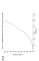
- FIG. 3 shows, as an example, one transfer function curve relationship for the digital projector.
- the processed images are projected under motion picture viewing conditions, according to the Society of Motion Picture and Television Engineers (SMPTE) standards, sending the data to the display device in full RGB resolution.
- SMPTE Society of Motion Picture and Television Engineers
Abstract
Description
- The present invention relates to the field of digital image processing. More specifically, it relates to the digital tone scale and color processing of negative or positive film images that have been digitized. This tone scale and color processing is optimized such that the digital images, when projected on a digital projector, match the colorimetry or appearance that a film projector would produce when projecting the motion picture print from the originating film.
- With the arrival of digital cinema, the necessity grows to achieve a high quality imaging system for consumers. The public has become accustomed to the traditional "film look" that they see when going to the movie theater. With digital cinema, digital projectors need to produce an image on the screen that preserves that "film look" since it is a pleasing and widely accepted look. After obtaining a digital image by scanning a motion picture film, the process of transforming the digital data, so that it has the "film-look" when it is projected on a digital projector, is a very tedious, costly and time-consuming process carried out by professionals known as colorists.
- U.S. Patent Nos. 5,809,164 and 5,239,370 disclose color management systems for emulating the "film-look" by focusing on gamut mapping or compression. Both patents assume that the capturing device has spectral sensitivities that are linear combinations of the CIE 2° Color Matching Functions. U.S. Patent No. 4,839,721 states that the transformation between the capture medium and the selected color space is performed with a substantially linearized response of the capture medium to the selected color space. It would be an advantage if the spectral sensitivities or response of the capturing device do not need to be a linear combination of the CIB 2° Color Matching Functions or of the selected color space.
- U.S. Patent No. 5,687,011 discloses a system in which a video image and a film image are simultaneously captured, and a computer reassigns color component data based on digital data representative of color component data within the image recorded on film. This is an impractical approach because of the necessity of having to concurrently record a film and a video image. It would be an advantage if there were no need to capture the scene on video to be able to do the transformation of the digital data to match film projection results.
- U.S. Patent No. 5,909,291 discloses a color matching system that initializes a translator by storing profiles of source and destination color devices which include the coordinates in a calibrated color space of the colorants produced in the source and destination devices and a tonal reproduction curve for each device. It would be an advantage if it were not necessary to store any profiles from source or destination devices.
- At the present time, professionals known as colorists spend a great amount of time empirically varying the tone scale and color of digitized film images to match, on a digital projector, the look that a film projector would have produced for the same material. A robust, straightforward method is needed that transforms film-originated and scanned digital images for digital projection so that the projected images emulate film projected images while, at the same time, eliminating the need for any manual adjustments to the color and tone scale of digitized images after the originating film has been adjusted for color and tone to create an acceptable release print.
- It is an object of the present invention to provide digital image processing wherein the spectral sensitivities or response of the capturing device do not need to be a linear combination of the CIE 2° Color Matching Functions or of the selected color space.
- It is another object of the present invention to provide digital image processing wherein there is no need to capture the scene on video to be able to do the transformation of the digital data to match film projection results.
- It is another object of the present invention to provide digital image processing wherein it is unnecessary to store any profiles from source or destination devices.
- It is another object of the present invention to provide digital image processing that achieves a colorimetric match between image "A" and image "B"; wherein image "A" is a motion picture film image that is projected under motion picture viewing conditions using a motion picture print film projection system, and image "B" is a digital image that originated on motion picture film and was transformed to digital domain by scanning the motion picture film, and that is displayed under the same viewing conditions as image "A", using a digital projector.
- It is another object of the present invention to provide digital image processing that achieves an appearance match between image "A" and image "C"; wherein image "C" is a digital image, that originated on motion picture film and was transformed to digital domain by scanning the motion picture film, using a motion picture film scanner, and that is projected under different viewing conditions to those of image "A", using a digital projector.
- It is another object of the present invention to provide a robust, straightforward method that transforms film originated and scanned digital images for digital projection so that they emulate film projected images, while, at the same time, eliminating the need for any manual adjustments to the color and tone scale of digitized images after the originating film has been adjusted for color and tone to create an acceptable release print.
- It is another object of the present invention to implement a robust, straightforward approach to creating a colorimetric match between digital images projected on a digital projector and film images projected on a film projector so that the digitally projected images emulate the film-projected images.
- It is another object of the present invention to provide a digital image processing method which can be easily modified to obtain an appearance match between the film-projected image and the digitally projected image when viewing conditions are different.
- It is another object of the present invention to provide digital image processing which takes advantages of the color adjustments made when creating a print release film, thereby avoiding any further manual adjustments to the color or tone scale of the images after they have been digitized.
- According to a feature of the present invention, scanner density values of a digitized image of an original film are processed so that a projection of the digitized image closely matches that image which a film projector would produce when projecting the original film. A method comprises the steps of transforming the scanner density values to printing density values; digital color balancing by writing the printing density values and a LAD patch onto film; printing the film according to the LAD procedure; transforming the images from device dependent color space values into device independent color space values; carrying out a relationship between the device independent color space and a display device output to obtain RGB code values; adjusting any non-linearity between the RGB code values and the display device output; and scaling the adjusted RGB code values to an appropriate bit depth.
- The invention, and its objects and advantages, will become more apparent in the detailed description of the preferred embodiments presented below.
- In the detailed description of the preferred embodiments of the invention presented below, reference is made to the accompanying drawings, in which:
- FIG. 1 is a schematic block diagram of a process according to the present invention to go from digitizing the film to device independent color values;
- FIG. 2 is a schematic block diagram of the process according to the present invention to go from device independent color values to a digital projector's RGB code values; and
- FIG. 3 shows one transfer function curve relationship for a digital projector.
-
- Referring to FIG. 1, film images and a Laboratory Aim Density (LAD) patch are digitized using a motion
picture film scanner 12. Utilizing LAD patches is disclosed in SMPTE Journal Volume 85, October 1976, in the article A Simplified Motion-Picture Laboratory Control Method for Improved Color Duplication, pages 781-785,by Pytlak and Fleischer. The resultingscanner density values 14 are transformed toprinting density values 16 by amatrix 18. The matrix may be obtained by regression between scanner density values and corresponding printing density values, a well know mathematical procedure to those skilled in the art. The use of one-dimensional Look-Up Tables (LUTs) is also available for this transformation. The scanner density and printing density terms are defined in the text Digital Color Management, by Giorgianni and Madden, pages 448-457. - After matrixing at 18, digital color balancing is carried out. Just as optical color balancing enhances color reproduction and overall density for conventionally printed images, digital color balancing enhances color reproduction and overall density when digital data is written to film and subsequently printed. Digital color balancing is effected by writing the transformed film images and LAD patch onto
film 22 using a motionpicture film recorder 20. The procedure of digitally recording images that originate on film is documented in SMPTE Journal Volume 102, December 1993, in the article Gray-Scale Transformations of Digital Film Data for Display, Conversion, and Film Recording, by Kennel and Snider. - Digitally recorded motion picture
negative film 22 is conventionally printed at 26 onto motionpicture print film 27 according to the LAD procedure; thus creating a "LAD Print." A discussion of printing of motion picture films is given in EASTMAN Professional Motion Picture Films, Kodak Publication H-1 (CAT 155 2280, 12-92-E Major Revision, Library of Congress Catalog Card No. 91-77432, ISBN 0-87985-477-4), pages 80-90. - The red, green, and blue light values in an additive printer can be adjusted by values, called "printer points" (also referred to in the art as "printer lights" in the Pytlak and Fleischer article). The printer points are integers from one to fifty, and are fed into
printer 26 from asource 28 by perforated paper tape, and are recorded on the film. A change of one printer point is equivalent to a change to the print film of 0.025 logE. A description of printer points is given on pages 88-89 of publication H-1, supra. Therefore, the operator of the printer always knows or can read from the paper tape the printer points used during the printing of any film. - Digitally recorded motion picture
negative film 22 is also printed onto motionpicture print film 30 to obtain a "Best Print." Experienced printing technicians (color-timers) carry out this step. Again, the printer points are recorded. - A Printing Exposure Difference value is determined at 32 from the printer points. The Printing Exposure Difference value is equal to 0.025 times the difference between the Printer Points recorded on LAD
Print 27 and the Printer Points recorded onBest Print 30. At 34, the Printing Exposure Difference value is multiplied by 12.5 to give a DigitalCode Value Difference 35. - A
multiplier 36 determines a FilmImage Code value 37 as the product of 500 timesPrinting Density values 16. At anAdder 38, Digital Color Balanced Code Values 39 are calculated by adding DigitalCode Value Difference 35 to the FilmImage Code values 37. This allows the images to be printed according to the LAD procedure and at the same time to be the best prints. Coming off Adder 38, Digital Color Balanced Code values are inputted to a MotionPicture Film Recorder 40 that is identical to Motion Picture Film Recorder 18. Recorder 40 writes the digital images and LAD patch onto afilm 42.Film 42 is printed, using aconventional printer 44 with printer points from asource 46, to make afilm print 48. This printing operation can be done using the LAD procedure. Because of the steps from 18 through 38,print 48 is also the best print. Although thesteps 18 through 48 may seem like overly complex steps, they are relatively easy to perform, the "rules" to perform them are well known in the motion picture industry, and the result is the best print in a straightforward way. In film labs that print motion picture film, the LAD procedure is well-established. In addition, the Digital Color Balanced Code Values out ofAdder 38 from different scenes of a movie can be digitally intercut with confidence that when the resulting movie is shown (whether by followingsteps 40 through 48 or by following a digital projection route following step 48) all of the scenes will be optimum for color and density. - The Digital Color Balanced Code Values from
Adder 38 are also transformed to a set of analytical density values by a set of three one-dimensional LUTs 50. These LUTs are determined from the characteristic curve, also known as the D-logE curve, of the print film material. The characteristic curve can be plotted as measured density on the y-axis and Code Value on the x-axis, where - The characteristic curve is normally measured as an integral density curve, for example, a "Status A Density" curve. Status A density is also known as integral density, and is a measure of the light absorbing power of a material. In film, the individual components absorbing the light are the base, the gelatin, the cyan dye, the magenta dye, the yellow dye, and any other absorbing materials in the film. The base, the gelatin, and the other absorbing materials usually absorb a constant fraction of the light independent of the amount of cyan, magenta, or yellow dyes. The cyan dye absorbs primarily red light, but also absorbs some green and some blue light. The magenta dye absorbs primarily green light, but also absorbs some red and blue light. The yellow dye absorbs primarily blue light, but also absorbs some red and green light. In order to calculate the color of any patch, it is important to know the amount of each dye in the patch. Analytical densities are proportional to the amounts of the dyes, not to the absorbing properties of the dyes. Therefore, a characteristic curve that shows the relationship between the analytical densities (y-axis) and the code values (x-axis) is more useful than a characteristic curve that shows the Status A densities (y-axis) and the code values (x-axis). For a description of printing density, integral density, analytical density, and conversions among them, see The Theory of The Photographic Process, by T.H. James, pages 517-535).
- The necessity for inter-image effects corrections will depend on how the motion picture print film behaves. In order to know if it is necessary to make a correction for inter-image effects, it is necessary to measure the print film. An experiment to run is described in the James book on page 534. Briefly, the film is exposed through a step tablet with one color light (red, green, or blue light). Next, the film is given a uniform exposure with the other two light colors. The film is processed, and the Status A densities are measured. The Status A densities are converted to analytical densities, and the analytical densities are plotted against the code values as explained above. The analytical densities corresponding to the dye associated with the light exposure through the step tablet will show variation from a low value to a high value. If there are no inter-image effects in the film, the other two analytical densities will be constant, and they will not have changed with the changes in the other dye. If there are inter-image effects in the film, the other two analytical densities will either increase or decrease, and they will have changed with the changes in the other dye. If necessary, a correction for inter-image effects is applied by a
matrix 52 to produce inter-image effects corrected Analytical Density values 54. The result of that matrix multiplication is a mathematical modeling of the chemical inter-image effects in the film. If there are no inter-image effects,matrix 52 is a unity matrix, and the set of three one-dimensional LUTs 50 andmatrix 52 can be combined into a set of three one-dimensional LUTs creating a direct relationship between printing density and analytical densities formed on the motion picture print film. - Dye set curves describe the spectral density curves of the imaging dyes in the film. Normalized dye set curves describe the spectral density curves of the imaging dyes in the film for a neutral reference. The spectral curve D(λ) for any color patch can be calculated from the equation:
- Thus, the c, m, and y analytical density values are used to modulate at 56 appropriately normalized print film dye set curves. Modulating these curves according to the analytical densities produces the spectrum, in density space, of the image formed in the motion picture print film. The density spectrum is then transformed to linear (transmittance) space to compute the device independent color values 58. The equation to go from density to transmittance is:
- It is possible to specify a color on a color monitor by specifying the drive values (code values) for the primaries of the monitor. However, these numbers depend on what the primaries are. If a person uses a different monitor with different primaries, a different set of code values are needed. An objective of the present invention is to express the color patch in device independent color values 58. That is, the color of the patch is specified by a set of numerical values that are independent of the device producing the colors. CIE XYZ (tristimulus) values are one such set of numbers. There are other numbers that could be used, for example CIELab coordinates, CIELuv coordinates, CIE x,y,Y coordinates, CIE u',v',Y coordinates, etc. The tristimulus values are defined as follows:

 where:
- Illum(λ) is the light source power spectrum,
- Optics(λ) represents the net spectra of any optical elements in the viewing path between the light source and the human eye,
-
x (λ)y (λ)z (λ) are the CIE 2° standard observer Color Matching Functions, - Trans(λ) is the transmittance spectrum of the object imaged in the motion picture print film, and
- k is a normalizing constant that makes Y equal to 100 for a 100% white reference.
- If a piece of white paper is viewed in one illuminant, say D50, it will appear white. If the same piece of white paper is viewed in another illuminant, say D65, it will again appear white. The eyes adapt to the illuminant such that a white appears white under most illuminants. Yet the XYZ tristimulus values will be different for the same piece of white paper in the two different illuminants. Although the XYZ values give a unique definition of color, this is only true relative to the illuminant. One therefore needs to modify the XYZ values for any shift in illuminants. Once device independent color space values 58 are obtained, any type of chromatic adaptation function can be applied to them. One example of this would be a VonKries chromatic adaptation, which is also documented in the text Digital Color Management, by Giorgianni and Madden, pages 479-481. The VonKries adaptation method is well known and works well for the types of illuminant changes one might encounter in a motion picture environment. There are other adaptation equations. The form of a VonKries adaptation equation is:where X', Y' and Z' are the chromatically adapted tristimulus values and M is the chromatic adaptation matrix. Giorgianni and Madden goes through an example of how to calculate M.

- In some implementations it will be reasonably fast to go through all of the calculations just described above for each pixel in the image. However, for other applications, to calculate each pixel by the above equations for each image will be too slow. Therefore, a faster implementation is needed. One faster alternative implementation can be a three-dimensional LUT (not shown). The three-dimensional LUT can be implemented in hardware and will provide very fast implementation of what we have described. The three-dimensional LUT values can be calculated using the above-described technique.
- Referring to FIG. 2, it is necessary to create a relationship between the device independent color space values 58 and RGB code values 60 for the display device, for example a digital projector. The relationship between device independent color space values and RGB code values for the display device can be characterized by a
matrixing operation 62. For an example of such a procedure see the report by the BBC Research and Development titled Television Colorimetry: A Tutorial for System Designers (BBC RD 1995/9), by Roberts. The following equation shows matrixing operation 62:where the XYZ vector represents the CIE XYZ tristimulus values associated with a set of RGB linear drive values, and M is
matrix 62 used for the transformation. - If the relationship between the light emitted by an intended
display device 64 is linearly related to RGB code values 60, then the RGB code values computed by matrixingoperation 62 are the values inputted to the digital display device, scaled up to the appropriate bit depth at 66. If the relationship between the light emitted by an intendeddisplay device 64 is non-linearly related to RGB code values 60, then the RGB code values computed by matrixingoperation 62 need to be adjusted by a transformation that characterizes the non-linear relationship before the code values are scaled up to the appropriate bit depth at 68. The transformation that characterizes the non-linear relationship can be implemented, as an example, with a one-dimensional LUT 70. It is important to mention that for a DLP (Digital Light Processing) digital projector, the inherent relationship between RGB code values 60 and light output is linear, but the hardware provides for a non-linear setting. This is to compensate for previously corrected video signals that were tailored for phosphor based display devices, which have an inherent non-linear relationship between RGB code values and light output. This is documented in the SPIE Proceedings Vol. 2666 paper, Video Processing for DLP Display Systems, by Markandey, Clatanoff and Pettitt of Texas Instruments, Inc., U.S.A. - Any type of dark surround adaptation or flare corrections can be applied to the RGB code values 60 for
display device 64 if the illumination levels or dark surround conditions where the display device is located do not match those conditions where traditional motion picture print film is viewed. These corrections are also documented in the text Digital Color Management, by Giorgianni and Madden, pages 474-478 and 484-488. FIG. 3 shows, as an example, one transfer function curve relationship for the digital projector. - Finally, the processed images are projected under motion picture viewing conditions, according to the Society of Motion Picture and Television Engineers (SMPTE) standards, sending the data to the display device in full RGB resolution.
Claims (10)
Applications Claiming Priority (2)
| Application Number | Priority Date | Filing Date | Title |
|---|---|---|---|
| US09/751,230 US6985253B2 (en) | 2000-12-28 | 2000-12-28 | Processing film images for digital cinema |
| US751230 | 2000-12-28 |
Publications (2)
| Publication Number | Publication Date |
|---|---|
| EP1223765A2 true EP1223765A2 (en) | 2002-07-17 |
| EP1223765A3 EP1223765A3 (en) | 2005-04-13 |
Family
ID=25021065
Family Applications (1)
| Application Number | Title | Priority Date | Filing Date |
|---|---|---|---|
| EP01204922A Withdrawn EP1223765A3 (en) | 2000-12-28 | 2001-12-17 | Processing film images for digital cinema |
Country Status (3)
| Country | Link |
|---|---|
| US (1) | US6985253B2 (en) |
| EP (1) | EP1223765A3 (en) |
| JP (1) | JP2002262125A (en) |
Families Citing this family (8)
| Publication number | Priority date | Publication date | Assignee | Title |
|---|---|---|---|---|
| KR20040085470A (en) * | 2003-03-31 | 2004-10-08 | 삼성전자주식회사 | Color conversion apparatus and color conversion method |
| EP2242247A3 (en) * | 2004-11-01 | 2012-07-25 | Technicolor, Inc. | Method and system for mastering and distributing enhanced color space content |
| US20060181721A1 (en) * | 2005-02-11 | 2006-08-17 | Kulkarni Manish S | Motion picture content preview |
| US20070146751A1 (en) * | 2005-10-05 | 2007-06-28 | Theodore Blase A | Color timing processes |
| JP2009521840A (en) * | 2005-12-21 | 2009-06-04 | トムソン ライセンシング | Limited color palette in color space |
| US8035654B1 (en) | 2007-08-17 | 2011-10-11 | Adobe Systems Incorporated | Tuning cell sizes in interpolated lookup tables |
| US8654192B2 (en) * | 2007-08-21 | 2014-02-18 | Adobe Systems Incorporated | Inter-image effect array for previewing digital motion picture content |
| US10832380B2 (en) | 2018-06-04 | 2020-11-10 | Disney Enterprises, Inc. | Systems and methods for correcting color for uncalibrated materials |
Citations (3)
| Publication number | Priority date | Publication date | Assignee | Title |
|---|---|---|---|---|
| US5917987A (en) * | 1996-08-16 | 1999-06-29 | Neyman; Yuri | System for controlling the transfer of an image on a first medium to a second medium |
| US6115062A (en) * | 1995-09-06 | 2000-09-05 | Eastman Kodak Company | Telecine reference element, system, and method for providing scene exposure information |
| WO2000064191A1 (en) * | 1999-04-16 | 2000-10-26 | Avid Technology, Inc. | Method and system for calibrating color correction instructions between color correction devices |
Family Cites Families (27)
| Publication number | Priority date | Publication date | Assignee | Title |
|---|---|---|---|---|
| US4839721A (en) | 1984-08-28 | 1989-06-13 | Polaroid Corporation | Method of and apparatus for transforming color image data on the basis of an isotropic and uniform colorimetric space |
| US4771342A (en) * | 1985-05-01 | 1988-09-13 | Emf Partners, Ltd. | Method and apparatus for enhancing video-recorded images to film grade quality |
| JPS628193A (en) * | 1985-07-04 | 1987-01-16 | インタ−ナショナル ビジネス マシ−ンズ コ−ポレ−ション | Color image display system |
| JPS627290A (en) * | 1985-07-04 | 1987-01-14 | Fuji Photo Film Co Ltd | Gradient correction for color negative film picking up image and its device |
| US5060061A (en) * | 1989-06-30 | 1991-10-22 | Victor Company Of Japan, Ltd. | Method of reading an image recorded in a photographic film tone characteristic correcting method in reproducing an image recorded in a photographic film |
| US5239370A (en) | 1990-04-24 | 1993-08-24 | Brother Kogyo Kabushiki Kaisha | Color image forming apparatus having color-correcting unit operating in accordance with a gamut of an image input medium |
| US5157506A (en) * | 1990-08-29 | 1992-10-20 | Savitar, Inc. | Standardized color calibration of electronic imagery |
| US5140414A (en) * | 1990-10-11 | 1992-08-18 | Mowry Craig P | Video system for producing video images simulating images derived from motion picture film |
| US5687011A (en) | 1990-10-11 | 1997-11-11 | Mowry; Craig P. | System for originating film and video images simultaneously, for use in modification of video originated images toward simulating images originated on film |
| US5457491A (en) * | 1990-10-11 | 1995-10-10 | Mowry; Craig P. | System for producing image on first medium, such as video, simulating the appearance of image on second medium, such as motion picture or other photographic film |
| US5185666A (en) * | 1991-08-05 | 1993-02-09 | Sony Corporation Of America | Digitized film image processing system with bordered split screen display |
| US5319465A (en) * | 1991-09-20 | 1994-06-07 | Sony Pictures Entertainment, Inc. | Method for generating film quality images on videotape |
| US5909291A (en) | 1992-03-19 | 1999-06-01 | Apple Computer, Inc. | Color matching apparatus and method |
| US5831673A (en) * | 1994-01-25 | 1998-11-03 | Przyborski; Glenn B. | Method and apparatus for storing and displaying images provided by a video signal that emulates the look of motion picture film |
| US5667944A (en) * | 1995-10-25 | 1997-09-16 | Eastman Kodak Company | Digital process sensitivity correction |
| US5809164A (en) | 1996-03-07 | 1998-09-15 | Polaroid Corporation | System and method for color gamut and tone compression using an ideal mapping function |
| US6346998B2 (en) * | 1996-11-20 | 2002-02-12 | Fuji Photo Film Co., Ltd. | Picture image outputting method and photograph finishing system using the method |
| US5891607A (en) * | 1997-09-15 | 1999-04-06 | Eastman Kodak Company | Color motion picture print film for use with digital output |
| JP3962496B2 (en) * | 1998-01-29 | 2007-08-22 | キヤノン株式会社 | Image processing method, apparatus, and recording medium |
| US7372485B1 (en) * | 1999-06-08 | 2008-05-13 | Lightsurf Technologies, Inc. | Digital camera device and methodology for distributed processing and wireless transmission of digital images |
| US6424740B1 (en) * | 1999-07-15 | 2002-07-23 | Eastman Kodak Company | Method and means for producing high quality digital reflection prints from transparency images |
| CA2325263A1 (en) * | 1999-11-11 | 2001-05-11 | Gretag Imaging Trading Ag | Optimization apparatus for photographic image data |
| US6781724B1 (en) * | 2000-06-13 | 2004-08-24 | Eastman Kodak Company | Image processing and manipulation system |
| US6864915B1 (en) * | 2000-10-27 | 2005-03-08 | Eastman Kodak Company | Method and apparatus for production of an image captured by an electronic motion camera/sensor that emulates the attributes/exposure content produced by a motion camera film system |
| US6987586B2 (en) * | 2001-03-02 | 2006-01-17 | Eastman Kodak Company | Method of digital processing for digital cinema projection of tone scale and color |
| US7053927B2 (en) * | 2001-03-02 | 2006-05-30 | Eastman Kodak Company | System for optimizing the display and rendering of digital images for digital mastering |
| AU2002335081A1 (en) * | 2001-10-04 | 2003-04-14 | E.I. Du Pont De Nemours And Company | Ink jet printing |
-
2000
- 2000-12-28 US US09/751,230 patent/US6985253B2/en not_active Expired - Fee Related
-
2001
- 2001-12-17 EP EP01204922A patent/EP1223765A3/en not_active Withdrawn
- 2001-12-21 JP JP2001389194A patent/JP2002262125A/en active Pending
Patent Citations (3)
| Publication number | Priority date | Publication date | Assignee | Title |
|---|---|---|---|---|
| US6115062A (en) * | 1995-09-06 | 2000-09-05 | Eastman Kodak Company | Telecine reference element, system, and method for providing scene exposure information |
| US5917987A (en) * | 1996-08-16 | 1999-06-29 | Neyman; Yuri | System for controlling the transfer of an image on a first medium to a second medium |
| WO2000064191A1 (en) * | 1999-04-16 | 2000-10-26 | Avid Technology, Inc. | Method and system for calibrating color correction instructions between color correction devices |
Non-Patent Citations (1)
| Title |
|---|
| J.P.PITLAK ET AL.: "A Simplified Motion-Picture Laboratory Control Method for Improved Color Duplication" SMPTE JOURNAL, vol. 85, no. 10, October 1976 (1976-10), pages 781-786, XP009044032 * |
Also Published As
| Publication number | Publication date |
|---|---|
| US6985253B2 (en) | 2006-01-10 |
| EP1223765A3 (en) | 2005-04-13 |
| US20020118211A1 (en) | 2002-08-29 |
| JP2002262125A (en) | 2002-09-13 |
Similar Documents
| Publication | Publication Date | Title |
|---|---|---|
| US6987586B2 (en) | Method of digital processing for digital cinema projection of tone scale and color | |
| EP1239668B1 (en) | System for optimizing the display and rendering of digital images for digital mastering | |
| JP3457363B2 (en) | Method and apparatus for reproducing images | |
| US7327382B2 (en) | System and method for processing electronically captured images to emulate film tonescale and color | |
| US5956044A (en) | Imaging device to media compatibility and color appearance matching with flare, luminance, and white point comparison | |
| JP2811595B2 (en) | Color image processing method | |
| JP3907783B2 (en) | Color conversion method | |
| EP1861998B1 (en) | Emulation of film image's tonescale and color | |
| KR101680254B1 (en) | Method of calibration of a target color reproduction device | |
| JPH0851636A (en) | Scanning of colored negative,and converting of original scene into colored one | |
| US20050280842A1 (en) | Wide gamut film system for motion image capture | |
| JP2004312748A (en) | Method of generating balanced digital color image having minimum color error | |
| US20060181721A1 (en) | Motion picture content preview | |
| US6985253B2 (en) | Processing film images for digital cinema | |
| US20080158351A1 (en) | Wide gamut film system for motion image capture | |
| KR20060121922A (en) | Method and system for color correction of digital image data | |
| US7369273B2 (en) | Grayscale mistracking correction for color-positive transparency film elements | |
| Giorgianni et al. | Color Encoding in the Photo CD System | |
| MADDEN | COLOR ENCODING| N THE PHOTO CD SYSTEM | |
| JPH11308471A (en) | Image processor | |
| Ha | Banding measurement for color laser printers color management system for digital cinema glare and shadow reduction | |
| Paul | A reference guide for desktop color reproduction |
Legal Events
| Date | Code | Title | Description |
|---|---|---|---|
| PUAI | Public reference made under article 153(3) epc to a published international application that has entered the european phase |
Free format text: ORIGINAL CODE: 0009012 |
|
| AK | Designated contracting states |
Kind code of ref document: A2 Designated state(s): AT BE CH CY DE DK ES FI FR GB GR IE IT LI LU MC NL PT SE TR |
|
| AX | Request for extension of the european patent |
Free format text: AL;LT;LV;MK;RO;SI |
|
| PUAL | Search report despatched |
Free format text: ORIGINAL CODE: 0009013 |
|
| AK | Designated contracting states |
Kind code of ref document: A3 Designated state(s): AT BE CH CY DE DK ES FI FR GB GR IE IT LI LU MC NL PT SE TR |
|
| AX | Request for extension of the european patent |
Extension state: AL LT LV MK RO SI |
|
| RIC1 | Information provided on ipc code assigned before grant |
Ipc: 7H 04N 1/60 B Ipc: 7H 04N 9/11 A |
|
| AKX | Designation fees paid | ||
| REG | Reference to a national code |
Ref country code: DE Ref legal event code: 8566 |
|
| STAA | Information on the status of an ep patent application or granted ep patent |
Free format text: STATUS: THE APPLICATION IS DEEMED TO BE WITHDRAWN |
|
| 18D | Application deemed to be withdrawn |
Effective date: 20051014 |