EP1556805B1 - Tracking a surface in a 3-dimensional scene using natural visual features of the surface - Google Patents
Tracking a surface in a 3-dimensional scene using natural visual features of the surface Download PDFInfo
- Publication number
- EP1556805B1 EP1556805B1 EP03796236A EP03796236A EP1556805B1 EP 1556805 B1 EP1556805 B1 EP 1556805B1 EP 03796236 A EP03796236 A EP 03796236A EP 03796236 A EP03796236 A EP 03796236A EP 1556805 B1 EP1556805 B1 EP 1556805B1
- Authority
- EP
- European Patent Office
- Prior art keywords
- image
- features
- tracking
- sequence
- feature
- Prior art date
- Legal status (The legal status is an assumption and is not a legal conclusion. Google has not performed a legal analysis and makes no representation as to the accuracy of the status listed.)
- Expired - Lifetime
Links
- 230000000007 visual effect Effects 0.000 title claims abstract description 15
- 238000000034 method Methods 0.000 claims description 55
- 239000003550 marker Substances 0.000 claims description 34
- 230000033001 locomotion Effects 0.000 claims description 18
- 230000001788 irregular Effects 0.000 claims 1
- 230000000153 supplemental effect Effects 0.000 claims 1
- 238000010586 diagram Methods 0.000 description 28
- 238000000605 extraction Methods 0.000 description 24
- 238000004364 calculation method Methods 0.000 description 15
- 230000009466 transformation Effects 0.000 description 13
- 238000001514 detection method Methods 0.000 description 11
- 230000008569 process Effects 0.000 description 10
- 230000003190 augmentative effect Effects 0.000 description 9
- 239000011159 matrix material Substances 0.000 description 9
- 230000006870 function Effects 0.000 description 7
- 238000002474 experimental method Methods 0.000 description 5
- 230000000875 corresponding effect Effects 0.000 description 4
- 238000013461 design Methods 0.000 description 4
- 238000012360 testing method Methods 0.000 description 4
- 238000013459 approach Methods 0.000 description 3
- 230000008901 benefit Effects 0.000 description 3
- 239000000284 extract Substances 0.000 description 3
- 230000006872 improvement Effects 0.000 description 3
- 238000012545 processing Methods 0.000 description 3
- 238000012935 Averaging Methods 0.000 description 2
- 238000012952 Resampling Methods 0.000 description 2
- 238000005516 engineering process Methods 0.000 description 2
- 238000005286 illumination Methods 0.000 description 2
- 230000002085 persistent effect Effects 0.000 description 2
- 238000010187 selection method Methods 0.000 description 2
- 238000013519 translation Methods 0.000 description 2
- PXFBZOLANLWPMH-UHFFFAOYSA-N 16-Epiaffinine Natural products C1C(C2=CC=CC=C2N2)=C2C(=O)CC2C(=CC)CN(C)C1C2CO PXFBZOLANLWPMH-UHFFFAOYSA-N 0.000 description 1
- 101100119135 Mus musculus Esrrb gene Proteins 0.000 description 1
- 241000950638 Symphysodon discus Species 0.000 description 1
- 230000001133 acceleration Effects 0.000 description 1
- 238000004458 analytical method Methods 0.000 description 1
- 230000003416 augmentation Effects 0.000 description 1
- 230000008859 change Effects 0.000 description 1
- 238000006243 chemical reaction Methods 0.000 description 1
- 230000002596 correlated effect Effects 0.000 description 1
- 230000001419 dependent effect Effects 0.000 description 1
- 238000006073 displacement reaction Methods 0.000 description 1
- 238000011156 evaluation Methods 0.000 description 1
- 238000001914 filtration Methods 0.000 description 1
- 238000003384 imaging method Methods 0.000 description 1
- 238000012886 linear function Methods 0.000 description 1
- 230000007246 mechanism Effects 0.000 description 1
- 230000008450 motivation Effects 0.000 description 1
- 230000003287 optical effect Effects 0.000 description 1
- 238000011084 recovery Methods 0.000 description 1
- 230000035945 sensitivity Effects 0.000 description 1
- 238000005211 surface analysis Methods 0.000 description 1
- 230000002123 temporal effect Effects 0.000 description 1
Images


Classifications
-
- G—PHYSICS
- G06—COMPUTING; CALCULATING OR COUNTING
- G06T—IMAGE DATA PROCESSING OR GENERATION, IN GENERAL
- G06T7/00—Image analysis
- G06T7/70—Determining position or orientation of objects or cameras
- G06T7/73—Determining position or orientation of objects or cameras using feature-based methods
- G06T7/74—Determining position or orientation of objects or cameras using feature-based methods involving reference images or patches
-
- G—PHYSICS
- G06—COMPUTING; CALCULATING OR COUNTING
- G06T—IMAGE DATA PROCESSING OR GENERATION, IN GENERAL
- G06T7/00—Image analysis
- G06T7/20—Analysis of motion
- G06T7/246—Analysis of motion using feature-based methods, e.g. the tracking of corners or segments
- G06T7/248—Analysis of motion using feature-based methods, e.g. the tracking of corners or segments involving reference images or patches
-
- G—PHYSICS
- G06—COMPUTING; CALCULATING OR COUNTING
- G06V—IMAGE OR VIDEO RECOGNITION OR UNDERSTANDING
- G06V10/00—Arrangements for image or video recognition or understanding
- G06V10/20—Image preprocessing
- G06V10/24—Aligning, centring, orientation detection or correction of the image
-
- G—PHYSICS
- G06—COMPUTING; CALCULATING OR COUNTING
- G06T—IMAGE DATA PROCESSING OR GENERATION, IN GENERAL
- G06T2207/00—Indexing scheme for image analysis or image enhancement
- G06T2207/10—Image acquisition modality
- G06T2207/10016—Video; Image sequence
Definitions
- the present invention is directed to the fields of computer vision and video processing.
- tracking the object consists of tracking the location and orientation of the object with respect to a camera-that is, the point in space that is the perspective from which the video scene is captured.
- One significant subset of the movement tracking task is tracking the movement of a roughly planar, i.e., 2-dimensional, surface within a video scene.
- a surface may be one side of a sheet of paper, either a free-standing sheet of paper or a sheet of paper in a book. It may also a surface presented by virtually any other object.
- One application of surface tracking is introducing a view of a virtual, 3-dimension object into each frame of the video scene that appears to floal about the surface, termed reality augmentation.
- Fiducial marker tracking involves affixing a special, visually distinct symbol (such as a bold black square having a white interior) to the surface to be tracked; locating the symbol-called a fiducial marker-in each video frame; determining the location of the surface with respect to the camera based on the size of the marker in the video frame and its location in the video frame; and determining the orientation of the surface with respect to the camera based on the orientation of the marker in the video frame.
- a special, visually distinct symbol such as a bold black square having a white interior
- Fiducial marker tracking has significant disadvantages, however.
- fiducial marker tracking fails any time the fiducial marker is not present in the scene. This can happen in a variety of circumstances, even while the surface remains in the scene.
- the fiducial marker may be occluded by an object that intervenes in space between the camera and the fiducial marker, such as a person's hand or another inanimate object.
- the fiducial marker may also move outside of the boundaries of the video scene, such as when the camera moves so close to (or zooms in so close to) the surface that the scene can only contain a portion of the surface that excludes the fiducial marker.
- This disadvantage can only be overcome by adding larger and larger numbers of fiducial markers to the surface, overwhelming the appearance of the surface and obscuring its innate visual features.
- fiducial marker tracking can fail when the surface is distant from the camera, and the camera's view of the surface is too limited to distinguish the fiducial marker.
- the only way to address this disadvantage is to use larger and larger fiducial markers, again overwhelming the appearance of the surface and obscuring its innate visual features.
- the disclosed multistage strategy includes three basic steps: image warping, motion residual estimation, and motion model refinement.
- Markerless Tracking using Planar Structures in the Scene PROCEEDINGS OF IEEE AND ACM INTERNATIONAL SYMPOSIUM ON AUGMENTED REALITY, October 2000, pages 120-128, Simon G. et al. describe a markerless camera tracking system for augmented reality that operates in environments which contain one or more planes. N interest points are detected in a frame i+1. Then, interest points from frame I are matched to interest points from frame i+1 to generate a set of correspondences, from which a 3x3 planar homography is computed. Then, camera position and rotation is computed from the planar homography, which provides motion estimates.
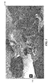
- Figure 1 is an image diagram showing a typical image that, when attached to a surface, can be tracked by the facility.
- Figure 2 is a flow diagram showing steps typically performed by the facility in order to track a surface.
- Figure 3 is a block diagram showing a typical environment in which the facility operates.
- Figure 4 is a pixel diagram showing the relationship between a window used in template matching and a search area within a video frame that contains it.
- Figure 5 is a pixel diagram that illustrates the feature point constraints for a candidate pixel.
- Figure 6A shows the output of this first step of the offline feature extraction algorithm for the original image resolution of 200 dpi.
- Figure 6B shows the output at a lower resolution of 100 dpi. Both of these figures reflect a template size of 25 x 25 pixels.
- Figure 7 is an image diagram showing sample features extracted from the image shown in Figure 1 .
- Figure 8 is a graph showing the experimental efficacy of different combinations of these prediction methods.
- Figures 9A-9C are tracking diagrams showing tracking results for various resolutions in a scene.
- Figures 10A and 10B are tracking diagrams showing tracking results under an occlusion condition.
- Figures 11A-11D are tracking diagrams showing tracking results for scenes under various degrees of rotation.
- Figures 12A and 12B are image diagrams showing sample images tracked by the facility.
- Figure 13 is a coordinate diagram showing the coordinate system used by the facility.
- Figures 14A and 14B are diagrams showing preliminary feature point extraction results.
- Figures 15A and 15B are diagrams showing preliminary feature point extraction results.
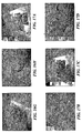
- Figures 16A-16H are tracking diagrams showing the results of sample tracking experiments.
- Figures 17A-17D show template matching results for example images.
- a software facility for tracking a surface in a 3-dimensional scene using natural visual features of the surface (“the facility") is provided.
- the facility acquires an image of the surface, and uses it to select visual features of the surface that the facility will use to track the surface.
- the facility performs this surface analysis and feature selection on a non-real-time basis.
- the facility selects groups of features that are each of a different size, for use when the surface is different distances from the camera.
- the facility locates a fiducial marker attached to the surface within the video scene, and uses it to determine the surface's distance and orientation relative to the camera.
- the facility reiteratively uses earlier tracking results to both (1) select a group of features to search for based upon the distance of the surface from the camera, and (2) delineate search zones in the video scene in which the facility expects to find the natural features based upon their prior positions. The facility then searches these search zones for the natural features in the selected group, and uses their locations in the video scene to determine the surface's location and orientation relative to the camera.
- the key idea to allow real-time tracking of natural features is to select beforehand the "best" features to track using an offline image processing program, and to choose an appropriate and fast matching method that will allow the detection and matching of these features in real-time during the online tracking phase. Based on these considerations, we chose points as the features to track, and template matching as the matching technique.
- Figure 1 is an image diagram showing a typical image that, when attached to a surface, can be tracked by the facility.
- the image has visual contents 100, including a fiducial marker 110.
- the offline extraction of the features to track greatly reduces the computation time and makes it possible to track the features in real-time: since the set of specific pixels to track is defined a priori, natural point features do not have to be extracted from each frame, but only to be tracked over time.
- the offline feature point extraction generates a set of fixed "natural corners" which perform exactly the same function as the artificial corners introduced by a marker, i.e. to be reference points whose coordinates are known in the object frame.
- the level of detail perceived by the camera changes dramatically.
- a black letter on a white background is a good feature to track when the camera is close to the planar scene, it might be that this same letter is not visible when the camera is far away from the scene.
- This problem can be solved by performing the offline feature extraction independently at different resolutions and adapting the set of features online as the camera moves.
- the general principle of natural-feature based tracking is the same as the marker-based tracking.
- Four coplanar feature points whose coordinates are known in the page and their projections in the image plane provide correspondences that allow calculating the planar homography and the extrinsic parameters.
- the main difference is that there are usually a lot more than four feature points available, thus providing a natural mechanism to cope with occlusions: if the tracked planar scene has a reasonable size, it is very unlikely that the user's hand will occlude all the available features in the image.
- the four "best" natural point features detected are selected as input for updating the homography.
- the updated homography is also used to generate new templates around the feature points, since the region around a pixel changes as the camera moves.
- the previous feature points' locations and displacement are used to predict their location in the next frame.
- the tracker estimates the current resolution of the planar scene as seen by the camera and changes the set of predefined features to track if appropriate.
- the camera pose is estimated and the virtual model can be rendered on the top of the book page.
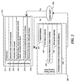
- FIG. 2 is a flow diagram showing steps typically performed by the facility in order to track a surface.
- the facility begins in market based initialization mode 210.
- the facility converts an image of the surface into binary form.
- the facility extracts connected components from the binary version of the image of the surface.
- the facility extracts the contours from the image of the surface.
- the facility rejects any false contours among the extracted contours, and performs sub-pixel recovery of the coordinates of the corners of the marker.
- the facility computes the homography of the surface (that is, its location and orientation relative to the camera), and un-warps the image of the surface by normalizing it with respect to the surface's determined location and orientation with respect to the camera.
- the facility selects the best visual features of the surface, such as the best four features. These selected features are sometimes referred to as "point features.”
- the facility enters a natural feature tracking mode 220.
- the facility updates the templates established during the marker-based initialization phase.
- the facility uses earlier tracking results to predict the locations in the video image at which the surface's point features will occur in the next video frame.
- the facility attempts to detect the point features near the predicted locations in the video frame using a template-matching process.
- the facility updates the surface's homography using the results of step 223.
- the facility evaluates the resolution in feature point selection for the next iteration of the natural feature tracking mode. In some embodiments, step 225 precedes step 221 in the natural feature tracking mode (not shown).
- the facility After completing the steps of natural feature tracking mode 220, the facility performs a test 230 to determine whether the most recent iteration of the natural feature tracking mode failed to track the surface in the video scene. If so, the facility continues in the marker-based initialization mode to re-locate the surface in the video scene, else the facility continues in the natural feature tracking mode to continue tracking the surface.
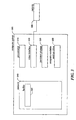
- FIG. 3 is a block diagram showing a typical environment in which the facility operates.
- the environment contains a computer system 300, which includes one or more processors 310 for executing programs, such as the facility; a video interface 320 that is connected to a camera 360 for acquiring individual images and/or video sequences comprised of images; a persistent storage device 330; a memory 340, containing at least the facility 341; and a computer-readable medium drive 350 for reading information or installing programs such as the facility from computer-readable media, such as a floppy disk, a CD-ROM, or a DVD.
- data and/or programs may be transferred between memory and the persistent storage device for purposes of memory management and data integrity. While various embodiments are described in terms of the environment described above, those skilled in the art will appreciate that the facility may be implemented in a variety of other environments including combinations of one or more computer systems or similar devices connected in various ways.
- This subsection illustrates the design of the feature extraction scheme that detects the best candidate points for template matching at different resolutions.
- the offline feature extraction method detects points for which template matching will work well. Therefore, the design of the feature extraction scheme is contingent on the design of the template matching technique. Assuming that the disparity between two successive video frames I k and I k+1 is small, then the criterion that can be used to match a point feature is similarity. For points, the universal measure of intensity similarity is correlation. Let p i be a feature point in I k , and W be a window of size w+1 and h +1 (with w and h odd numbers) centered on p i . W defines the template to look for in I k+1 .
- FIG. 4 is a pixel diagram showing the relationship between a window used in template matching and a search area within a video frame that contains it.
- Rectangle 400 is the video frame I k+1 .
- Rectangle 410 is the search area.
- Rectangle 420 is the search window W, centered on pixel 430 at (y 0 , x 0 ). Window W spans columns x 0 - w/2 through x 0 + w/2, and spans rows y 0 - w/2 through y 0 + w/2.
- Finding the pixel in I k+i that is most likely to correspond to p i is equivalent to finding the region of size w+1 and h +1 in I k+1 that has the highest correlation score with W within the search area.
- NCC scores between -1 and 1 providing an intuitive range to perform similarity thresholding: a value of -1 indicates no similarity at all whereas a value of 1 shows perfect similarity.
- Another benefit of using the NCC comes from its insensitivity to illumination changes. If we model an illumination change by the addition of a constant value to all the pixels of the regions, then the score of the NCC will be the same as without that offset. However, correlation is not insensitive to any affine or perspective transformation. Therefore, templates will be generated for each frame grabbed by the system as mentioned above.
- NCC is computationally expensive and can become inefficient when the values of w, h and the size of the search area become large.
- a coarse to fine technique will be used: firstly, template matching within the search window is carried out every n pixels to reduce the search complexity by a factor n. The three positions for which the NCC score was the highest are stored. Then the fine search is carried out: template matching is performed for every pixel in the regions around the three stored positions. The highest NCC score provides the final detected position.
- a front-facing representation of the planar scene to track containing a marker has to be supplied to the tracker.
- a JPEG or a GIF file is used as the input image file.
- the marker is detected in the input image using well known techniques, such as those described in U.S. Provisional Patent Application No. 60/513,725 (patent counsel's docket no. 37181-8002US00).
- the position and size of the scene in the input image are calculated and stored in a file.
- Figure 5 is a pixel diagram that illustrates the feature point constraints for a candidate pixel.
- the candidate pixel 501 is likely to be a good feature within template 503 if: (1) the similarity within a small circular region 502 about the candidate pixel is high; (2) the similarity inside the template 503 and outside the circular region 502 is low, i.e., there is a high variance; and (3) no similar template regions exist within search area 504.
- the offline feature extraction program proceeds thus: the user gives in the different resolutions for which he or she would like the features to be automatically extracted. The more resolutions are specified, the more accurate the tracker will be but the more processing time will be required.
- the parameters that have to be fixed for the natural feature extraction are:
- Figure 6A shows the output of this first step of the offline feature extraction algorithm for the original image resolution of 200 dpi.
- Figure 6B shows the output at a lower resolution of 100 dpi.
- Both of these figures reflect a template size of 25 x 25 pixels.
- dark regions indicate highly correlated regions (uniform regions) from which feature points should not be chosen.
- bright regions are image regions for which template matching is likely to work well. As expected, fewer details are visible in the image with lower resolution.
- FIG. 7 is an image diagram showing sample features extracted from the image shown in Figure 1 .
- This subsection describes an efficient tracking algorithm of predefined features which allows continued pattern tracking in the presence of significant occlusion.
- the fundamental idea is to track the known point feature from frame to frame, and to update the homography for the planar scene based on these natural features, instead of simply relying on the four artificial corners provided by the marker.
- the initialization of the tracker is made using the fiducial marker as described in Section 1.2.
- the tracker has to decide which natural features are the "best" ones to choose in the current frame. Keeping in mind the fact that our application must run in real-time, we want to choose as few features as possible whose locations are optimal. Therefore, the following heuristic selection method is chosen:
- the first stage of the tracking mode consists of predicting the location of the features in the current frame using the homography computed in the previous frame. Assuming temporal coherency, three simple prediction methods can be derived.
- the estimated positions of the features are subject to errors due to small errors in the homography as well as due to the approximations introduced in Section 4.4.2.
- a search window around that position has to be defined to proceed with template matching. The tricky task is to fix the size of this search area.
- a simple approach is to declare its size constant, and to set it to a value determined empirically by tests in real conditions. This approach is very simple and may not be well adapted to dynamic motions, yet it is the basis of our system since we extracted features assuming a fixed search window size.
- a large search window allows for more movement, but slows down the matching process since normalized cross correlation has to be carried out for a large number of pixels.
- a small search window size increases the speed of the matching process, but increases the chance of tracker failure due to rapid motion. Please refer to Section 3 for the empirical determination of the window size.
- the position of the selected features is determined by the template matching process described in 1.1 (typically, a match is found if the NCC score is greater than 0.7) and the
- ⁇ is smaller than a predefined threshold (a value of 5.0 has proven to be a useful threshold value)
- a predefined threshold a value of 5.0 has proven to be a useful threshold value
- the homography is accepted and another tracking cycle can begin with the next video frame. If ⁇ is greater than the threshold, it may indicate that the set of point correspondences contains a spurious value due to noise or occlusion.
- the search for a fifth feature point is carried out. If one additional feature point is detected, the planar homography is computed for every subset of four points among five and the one that minimizes ⁇ is chosen as the result. If a fifth feature point cannot be detected, tracking fails and the tracker reverts to the initialization mode. The fiducial marker has to be in view for the tracker to be re-initialized.
- an estimate of the viewed resolution of the planar scene is computed as follows: two feature points whose coordinates are known in the world frame and in the image frame are chosen. We know the distance in millimeters separating the two features in the world frame and the distance in pixels separating them in the image frame. Consequently, it is easy to know how many pixels represent a centimeter in world coordinates and to deduce the resolution of the scene that the camera is currently viewing. If necessary, a different set of features corresponding to that resolution is chosen.
- the feature prediction method has a direct influence on the size of the search area.
- a small search area would make faster the matching process but would cause tracking to fail due to the coarse nature of the prediction method. This means that a too small value of w search will give a higher chance of the tracked feature not being in the search area and causing the tracker to fail.
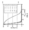
- the error rate representing the percentage of feature points that were not detected in the search area was calculated as a function of the search area size. The results are shown in Figure 8 .
- Figure 8 is a graph showing the experimental efficacy of different combinations of these prediction methods.
- the graph 800 is encoded using a key 810, in which the numeral 1 refers to prediction method (2.3.1), the numeral 2 refers to prediction method (2.3.2), and the numeral 3 refers to prediction method (2.3.3).
- prediction method (2.3.1) gives poor results unless the search window size is large. Furthermore, we observe that any combination of two prediction methods or of the three together gives similar results. To choose a search area size, we look more in details in the range between 41 and 61 pixels to see what value provides an acceptable error rate for every prediction method. The results are shown in Table 1 below.
- the combination of prediction methods (2.3.1) and (2.3.2) is chosen to reduce the time needed by the prediction stage of the tracker. Consequently, a search area size of 49 is selected since it is the minimum size guaranteeing that the feature points will be found in the search area.
- augmented reality system One of the major design goals of our augmented reality system was real-time performance on a standard personal computer.
- the software runs under the Windows XP operating system and the camera used is an off-the-shelf USB web camera delivering 640 pixel x 480 pixel video frames.
- the tracking system is currently implemented in C with OpenGL and VRML used to render the augmented graphics on top of the video. All tests have been run on an Intel Pentium IV 2.4 GHz processor, with a GeForce4 Ti 4600 video card.
- the offline feature extraction is the bottleneck of the whole application because of its algorithmic complexity.
- the processing time can be a few minutes.
- the size of the input becomes large, as it is the case for our application (3800 pixels x 1920 pixels)
- the time needed to generate the feature map at different resolutions is more than five hours. This remains the main drawback of the application.
- the scale invariance is tested by starting tracking with the camera far away from the scene and gradually taking it closer to the scene.
- the multi-resolution template scheme works well as shown in Figures 9A-9C .
- Figures 9A-9C are tracking diagrams showing tracking results for various resolutions in a scene.
- Figure 9A shows tracking results for a low resolution
- Figure 9B for a medium resolution
- Figure 9C for a high resolution.
- the numbered green squares in these figures represents the current point features tracked.
- a zoomed view of the templates can be seen on the left side of each figure.
- Occlusion handling is then tested with a typical user's reaction: putting a hand over the scene to track.
- the tracker succeeds in choosing alternative feature points, thus providing continuous tracking.
- the results for occlusion are shown in Figures 10A and 10B .
- Figures 10A and 10B are tracking diagrams showing tracking results under an occlusion condition.
- Figure 10A shows tracking results for a scene that is not occluded
- Figure 10B shows tracking results for a similar scene that is occluded by a human hand. Because the occlusion of feature 2 shown in Figure 10A is prevented in the scene shown in Figure 10B by the occlusion, the facility proceeds to register a new feature in the scene of Figure 10B , shown there as feature number 4.
- Figures 11A-11D are tracking diagrams showing tracking results for scenes under various degrees of rotation.
- Figure 11A shows tracking results under no rotation
- Figure 11B under rotation of 45°
- Figure 11C under rotation of 60°
- Figure 11D under rotation of 80°.
- One limitation of some embodiments of the tracker is its sensitivity to rapid motion. If the camera is rotated or translated quickly, the tracker usually fails. This is due to the poor image quality delivered by a simple USB web camera. When the camera moves quickly, the frame provided by the camera is too blurred for template matching to succeed. The use of a higher quality camera with higher shutter-speed should increase considerably the robustness of the tracker to rapid image motion.
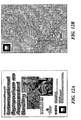
- Figures 12A and 12B are image diagrams showing sample images tracked by the facility.
- the image of Figure 12A consists of letters and photos and has a size of about 20 cm by 28 cm.
- the image of Figure 12B is an example of a color map, and is of size of about 80 cm by 104 cm.
- Figure 13 is a coordinate diagram showing the coordinate system used by the facility.
- the origin of the object coordinates, X o and Y o axes lie on the surface, while the Z o axis is perpendicular to the surface.
- the camera has a camera coordinate frame and there is a perspective relationship between the camera coordinates and the screen coordinates.
- Straight lines in the 3D environment should ideally remain straight when transformed into screen coordinates. However in practice this does not happen because of lens distortion.
- T co minimizes this error function. If n is more than 3 and suitable initial values are given for T co , this calculation is possible. We employ the functions provided by ARToolKit for this calculation. In order to set suitable initial values into T co , the result for previous frame is used in iterative tracking phase. A black square fiducial and ARToolKit functions are used to set the initial values in initial detection phase.
- Template matching can detect similar regions to the template from images.
- templates In general templates have to be prepared beforehand. However this is impossible with this kind of 3D tracking, because the image of a feature point varies by its 6 DOF movement. Therefore the templates have to be generated for each image frame. We assume that the movement of the tracked object is small between each continuous image frame. Then templates are generated from the texture image of the tracked object that is captured beforehand based on the pose and position information in previous frame. Detection of feature positions consists of the following three steps:
- x i is a pixel value
- x i is the mean of pixel values
- y i is a template value
- y i is the mean of template values.
- the calculated value is between -1.0 and 1.0.
- the position where the biggest value is found matches the corresponding position (x di , y di ) in observed screen coordinates to feature position ( X oi , Y oi , 0) in object coordinates.
- T co can be found for the current image frame using the calculation in previous section.
- Templates can be generated by using (eq.6.6), however if the resolution of the texture image is quite different from the resolution of generated templates, the expected templates cannot be found because of the resampling problem. If an interpolation technique is used in resampling, it could be avoided. But it requires much calculation cost. To overcome this some textured images with several resolutions need to be prepared beforehand.
- Feature points in texture images are registered with our software beforehand so they can be used for template matching.
- suitable feature points for template matching depend on the resolution. For example, when the camera is near to the tracked object, the resolution of observed image is high and small letters in the image can be used as feature points. On the other hand, when the camera is far from the tracked object, the resolution of observed image is low and small letters cannot be resolved. To compensate for this suitable feature points are independently registered for different resolutions of the texture image.
- the most important feature selection policy is that four feature points are detected from images. If this is impossible, detection of three feature points is needed. If fewer than three feature points are detected, then tracking fails.
- template matching is done for the selected feature. If the template matching succeeds, in other words the maximal value of normalized correlation is greater than 0.7, the feature point are stored and selection of next feature point is continued. If the template matching fails, the feature point is rejected and selection of an alternative feature point is continued.
- the conditions used by this selection policy are as follows:
- the transformation matrix T co is calculated from them based on (eq.6.4). If the error is less than a certain value (5.0 in experiments), the object tracking succeeds. If not, missed detections might be included and the detection of a fifth feature point is carried out. If one is found, the transformation matrices T co are calculated for all combinations of four feature points in the set of five points. Then the transformation matrix with minimum error is picked up as a result. If the detection of a fifth feature point fails, transformation matrices T co are calculated for all combinations of three feature points in the set of four points. Then the transformation matrix with minimum error is picked up as a result. If the minimum error value is greater than a threshold, the object tracking fails.
- Normalized correlation has a high calculation cost while it detects matching point well.
- template matching To reduce the calculation cost, we employ two steps template matching. First of all, a coarse search is carried out. In scanning on the search area, template matching is done once for every 3 pixels in the x direction and the positions of best three results are stored. Also (eq.6.9) is used for this template matching.
- I ( i,j ) is a pixel value at position ( i, j ) in the region on which template overlaps
- I is an average pixel values in the region in which the template overlaps
- T ( i , j ) is a pixel value at position ( i , j ) in the template
- T is an average pixel value in the template.
- the template size is 24x12 pixels. However this calculation uses one pixel in every two pixels so the calculation cost is reduced.
- a normalized correlation with a 24x12 template size is used based on (eq.6.7) in regions around the previously obtained three positions. Then the position with highest correlation value is found as the result.
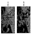
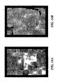
- Figures 14A and 14B are diagrams showing preliminary feature point extraction results.
- Figure 14A shows preliminary feature point extraction results for the image of Figure 12A while Figure 14B shows preliminary feature point extraction results for the image of Figure 12B .
- Bright pixels in these images means little correlation value, that is, bright position are suitable for condition 1 as a feature point.
- the square marker regions in the images are also omitted from this calculation.
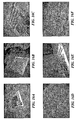
- Figures 15A and 15B are diagrams showing preliminary feature point extraction results.
- Figure 15A shows preliminary feature point extraction results for the image of Figure 12A while Figure 15B shows preliminary feature point extraction results for the image of Figure 12B .
- Each figure shows feature points extracted at three different levels of resolutions: feature points identified by red boxes at a high level of resolution, feature points identified by green boxes at a medium level of resolution, and feature points identified by blue boxes at a low level of resolution.
- Figures 16A-16H are tracking diagrams showing the results of sample tracking experiments. We can see virtual objects are suitably overlaid on the tracked objects in some conditions.
- Figures 17A-17D show template matching results for example images.
- the rectangles arrayed along the left edge of each figure show the feature templates generated by the facility for the matched features. Green rectangle regions in images are accepted matching regions and yellow rectangle regions are rejected regions. We can see template matching is attempted until 4 matching regions are found. So registration works well even when textures are occluded by a hand.
- Another problem was pose and position calculation from 3 feature points. When 3 feature points are almost in a straight line, the registration was bad and it caused tracking to fail in next frame. So the condition to select 3 feature points in the set of 4 points has to be considered.
Abstract
Description
- The present invention is directed to the fields of computer vision and video processing.
- One task faced in the field of computer vision is tracking the movement of an object within a video scene. In many cases, tracking the object consists of tracking the location and orientation of the object with respect to a camera-that is, the point in space that is the perspective from which the video scene is captured.
- One significant subset of the movement tracking task is tracking the movement of a roughly planar, i.e., 2-dimensional, surface within a video scene. Such a surface may be one side of a sheet of paper, either a free-standing sheet of paper or a sheet of paper in a book. It may also a surface presented by virtually any other object. One application of surface tracking is introducing a view of a virtual, 3-dimension object into each frame of the video scene that appears to floal about the surface, termed reality augmentation.
- Surface tracking has conventionally been addressed through the use of fiducial marker tracking. Fiducial marker tracking involves affixing a special, visually distinct symbol (such as a bold black square having a white interior) to the surface to be tracked; locating the symbol-called a fiducial marker-in each video frame; determining the location of the surface with respect to the camera based on the size of the marker in the video frame and its location in the video frame; and determining the orientation of the surface with respect to the camera based on the orientation of the marker in the video frame.
- Fiducial marker tracking has significant disadvantages, however. First, fiducial marker tracking fails any time the fiducial marker is not present in the scene. This can happen in a variety of circumstances, even while the surface remains in the scene. For example, the fiducial marker may be occluded by an object that intervenes in space between the camera and the fiducial marker, such as a person's hand or another inanimate object. The fiducial marker may also move outside of the boundaries of the video scene, such as when the camera moves so close to (or zooms in so close to) the surface that the scene can only contain a portion of the surface that excludes the fiducial marker. This disadvantage can only be overcome by adding larger and larger numbers of fiducial markers to the surface, overwhelming the appearance of the surface and obscuring its innate visual features.
- Second, fiducial marker tracking can fail when the surface is distant from the camera, and the camera's view of the surface is too limited to distinguish the fiducial marker. The only way to address this disadvantage is to use larger and larger fiducial markers, again overwhelming the appearance of the surface and obscuring its innate visual features.
- In view of these shortcomings, an approach to surface tracking that does not rely on the continuous visibility and distinguishability of fiducial markers affixed to the surface would have significant utility. In "Natural Feature Tracking for Augmented Reality", IEEE TRANSACTIONS ON MULTIMEDIA, Vol. 1, No. 1, March 1999, Neumann, U. and You, S. discuss natural feature tracking for augmented reality. It is described that natural scene features stabilize and extend the tracking range of augmented reality pose-tracking systems. Robust computer vision methods to detect and track natural features in video images are disclosed. It is suggested to automatically and adaptively select point and region features for properties that lead to robust tracking. A multistage tracking algorithm is disclosed that produces accurate motion estimates, wherein the entire system operates in a closed loop that stabilizes its performance and accuracy. The disclosed multistage strategy includes three basic steps: image warping, motion residual estimation, and motion model refinement.
In "Markerless Tracking using Planar Structures in the Scene", PROCEEDINGS OF IEEE AND ACM INTERNATIONAL SYMPOSIUM ON AUGMENTED REALITY, October 2000, pages 120-128, Simon G. et al. describe a markerless camera tracking system for augmented reality that operates in environments which contain one or more planes. N interest points are detected in a frame i+1. Then, interest points from frame I are matched to interest points from frame i+1 to generate a set of correspondences, from which a 3x3 planar homography is computed. Then, camera position and rotation is computed from the planar homography, which provides motion estimates.
It is the object of the present invention to enable an improved determination of the 3-dimensional location and orientation of a subject surface in a distinguished perspective image of the subject surface.
The object is solved by the subject matter of the independent claims.
Preferred embodiments of the present invention are defined by the dependent claims. -
Figure 1 is an image diagram showing a typical image that, when attached to a surface, can be tracked by the facility. -
Figure 2 is a flow diagram showing steps typically performed by the facility in order to track a surface. -
Figure 3 is a block diagram showing a typical environment in which the facility operates. -
Figure 4 is a pixel diagram showing the relationship between a window used in template matching and a search area within a video frame that contains it. -
Figure 5 is a pixel diagram that illustrates the feature point constraints for a candidate pixel. -
Figure 6A shows the output of this first step of the offline feature extraction algorithm for the original image resolution of 200 dpi. -
Figure 6B shows the output at a lower resolution of 100 dpi. Both of these figures reflect a template size of 25 x 25 pixels. -
Figure 7 is an image diagram showing sample features extracted from the image shown inFigure 1 . -
Figure 8 is a graph showing the experimental efficacy of different combinations of these prediction methods. -
Figures 9A-9C are tracking diagrams showing tracking results for various resolutions in a scene. -
Figures 10A and 10B are tracking diagrams showing tracking results under an occlusion condition. -
Figures 11A-11D are tracking diagrams showing tracking results for scenes under various degrees of rotation. -
Figures 12A and 12B are image diagrams showing sample images tracked by the facility. -
Figure 13 is a coordinate diagram showing the coordinate system used by the facility. -
Figures 14A and 14B are diagrams showing preliminary feature point extraction results. -
Figures 15A and 15B are diagrams showing preliminary feature point extraction results. -
Figures 16A-16H are tracking diagrams showing the results of sample tracking experiments. -
Figures 17A-17D show template matching results for example images. - A software facility for tracking a surface in a 3-dimensional scene using natural visual features of the surface ("the facility") is provided. In some embodiments, the facility acquires an image of the surface, and uses it to select visual features of the surface that the facility will use to track the surface. In some embodiments, the facility performs this surface analysis and feature selection on a non-real-time basis. In some embodiments, the facility selects groups of features that are each of a different size, for use when the surface is different distances from the camera. To initially identify the surface in the video frame, in some embodiments, the facility locates a fiducial marker attached to the surface within the video scene, and uses it to determine the surface's distance and orientation relative to the camera. After this point, the facility reiteratively uses earlier tracking results to both (1) select a group of features to search for based upon the distance of the surface from the camera, and (2) delineate search zones in the video scene in which the facility expects to find the natural features based upon their prior positions. The facility then searches these search zones for the natural features in the selected group, and uses their locations in the video scene to determine the surface's location and orientation relative to the camera.
- The key idea to allow real-time tracking of natural features is to select beforehand the "best" features to track using an offline image processing program, and to choose an appropriate and fast matching method that will allow the detection and matching of these features in real-time during the online tracking phase. Based on these considerations, we chose points as the features to track, and template matching as the matching technique.
-
Figure 1 is an image diagram showing a typical image that, when attached to a surface, can be tracked by the facility. The image hasvisual contents 100, including afiducial marker 110. - The offline extraction of the features to track greatly reduces the computation time and makes it possible to track the features in real-time: since the set of specific pixels to track is defined a priori, natural point features do not have to be extracted from each frame, but only to be tracked over time. In other words, the offline feature point extraction generates a set of fixed "natural corners" which perform exactly the same function as the artificial corners introduced by a marker, i.e. to be reference points whose coordinates are known in the object frame. However, as the camera pans in or pans out, the level of detail perceived by the camera changes dramatically. For example, a black letter on a white background is a good feature to track when the camera is close to the planar scene, it might be that this same letter is not visible when the camera is far away from the scene. This problem can be solved by performing the offline feature extraction independently at different resolutions and adapting the set of features online as the camera moves.
- In all other respects, the general principle of natural-feature based tracking is the same as the marker-based tracking. Four coplanar feature points whose coordinates are known in the page and their projections in the image plane provide correspondences that allow calculating the planar homography and the extrinsic parameters. The main difference is that there are usually a lot more than four feature points available, thus providing a natural mechanism to cope with occlusions: if the tracked planar scene has a reasonable size, it is very unlikely that the user's hand will occlude all the available features in the image.
- One drawback of the natural feature tracking however is that the tracker's initialization appears to be a delicate task: detecting four natural feature points in the first video frame requires template matching on the whole image for every single possible feature point. This search is computationally expensive and ineffective if the video frame does not provide a perpendicular view of the scene to track. To overcome this drawback, a marker is placed on the page to provide the initial homography as described further below. This homography is used to un-warp the image so that the tracker has a perpendicular view of the scene. From there the tracker knows where to look for the predefined natural point features and no longer needs the marker to be in view. A search size is fixed and template matching is carried out in windows around the predicted feature points' positions. The four "best" natural point features detected are selected as input for updating the homography. The updated homography is also used to generate new templates around the feature points, since the region around a pixel changes as the camera moves. The previous feature points' locations and displacement are used to predict their location in the next frame. Then the tracker estimates the current resolution of the planar scene as seen by the camera and changes the set of predefined features to track if appropriate. Finally, the camera pose is estimated and the virtual model can be rendered on the top of the book page.
-
Figure 2 is a flow diagram showing steps typically performed by the facility in order to track a surface. The facility begins in market basedinitialization mode 210. Instep 211, the facility converts an image of the surface into binary form. Instep 212, the facility extracts connected components from the binary version of the image of the surface. Instep 213, the facility extracts the contours from the image of the surface. Instep 214, the facility rejects any false contours among the extracted contours, and performs sub-pixel recovery of the coordinates of the corners of the marker. Instep 215, the facility computes the homography of the surface (that is, its location and orientation relative to the camera), and un-warps the image of the surface by normalizing it with respect to the surface's determined location and orientation with respect to the camera. Instep 216, the facility selects the best visual features of the surface, such as the best four features. These selected features are sometimes referred to as "point features." - After the steps of the marker-based
initialization mode 210 are completed, the facility enters a naturalfeature tracking mode 220. Instep 221, the facility updates the templates established during the marker-based initialization phase. Instep 222, the facility uses earlier tracking results to predict the locations in the video image at which the surface's point features will occur in the next video frame. Instep 223, the facility attempts to detect the point features near the predicted locations in the video frame using a template-matching process. Instep 224, the facility updates the surface's homography using the results ofstep 223. Instep 225, the facility evaluates the resolution in feature point selection for the next iteration of the natural feature tracking mode. In some embodiments,step 225 precedesstep 221 in the natural feature tracking mode (not shown). - After completing the steps of natural
feature tracking mode 220, the facility performs atest 230 to determine whether the most recent iteration of the natural feature tracking mode failed to track the surface in the video scene. If so, the facility continues in the marker-based initialization mode to re-locate the surface in the video scene, else the facility continues in the natural feature tracking mode to continue tracking the surface. -
Figure 3 is a block diagram showing a typical environment in which the facility operates. The environment contains acomputer system 300, which includes one ormore processors 310 for executing programs, such as the facility; avideo interface 320 that is connected to acamera 360 for acquiring individual images and/or video sequences comprised of images; apersistent storage device 330; amemory 340, containing at least thefacility 341; and a computer-readable medium drive 350 for reading information or installing programs such as the facility from computer-readable media, such as a floppy disk, a CD-ROM, or a DVD. Those skilled in the art will appreciate that data and/or programs may be transferred between memory and the persistent storage device for purposes of memory management and data integrity. While various embodiments are described in terms of the environment described above, those skilled in the art will appreciate that the facility may be implemented in a variety of other environments including combinations of one or more computer systems or similar devices connected in various ways. - This subsection illustrates the design of the feature extraction scheme that detects the best candidate points for template matching at different resolutions.
- The offline feature extraction method detects points for which template matching will work well. Therefore, the design of the feature extraction scheme is contingent on the design of the template matching technique. Assuming that the disparity between two successive video frames Ik and Ik+1 is small, then the criterion that can be used to match a point feature is similarity. For points, the universal measure of intensity similarity is correlation. Let pi be a feature point in Ik, and W be a window of size w+1 and h+1 (with w and h odd numbers) centered on p i. W defines the template to look for in Ik+1.
-
Figure 4 is a pixel diagram showing the relationship between a window used in template matching and a search area within a video frame that contains it.Rectangle 400 is the video frame Ik+1. Rectangle 410 is the search area.Rectangle 420 is the search window W, centered onpixel 430 at (y0, x0). Window W spans columns x0 - w/2 through x0 + w/2, and spans rows y0 - w/2 through y0 + w/2. - Finding the pixel in Ik+i that is most likely to correspond to p i is equivalent to finding the region of size w+1 and h+1 in Ik+1 that has the highest correlation score with W within the search area. Normalized cross-correlation (NCC)-discussed in F. Vial, "State of the Art Report on Natural Feature Tracking for Vision - Based Real-Time Augmented Reality", Technical Report, Human Interface Technology Laboratory New Zealand (HITLab NZ), University of Canterbury, Christchurch, New Zealand, 2003, has shown to be an effective point correlation method. To calculate the NCC between a template Wand a region of the same size around a pixel (x0, y0) in Ik+1, the intensity values for the considered pixels have to be centered. Let i and j be indexes spanning a square region of the same size as W. Then

are the centered values of the pixel (i,j) within the considered region in I k+1, and W respectively, with
and
Then, the normalized cross correlation score between W and the region around (x 0,y 0) yields:
- An advantage is that the NCC scores between -1 and 1, providing an intuitive range to perform similarity thresholding: a value of -1 indicates no similarity at all whereas a value of 1 shows perfect similarity. Another benefit of using the NCC comes from its insensitivity to illumination changes. If we model an illumination change by the addition of a constant value to all the pixels of the regions, then the score of the NCC will be the same as without that offset. However, correlation is not insensitive to any affine or perspective transformation. Therefore, templates will be generated for each frame grabbed by the system as mentioned above.
- Moreover, NCC is computationally expensive and can become inefficient when the values of w, h and the size of the search area become large. To compensate for this, a coarse to fine technique will be used: firstly, template matching within the search window is carried out every n pixels to reduce the search complexity by a factor n. The three positions for which the NCC score was the highest are stored. Then the fine search is carried out: template matching is performed for every pixel in the regions around the three stored positions. The highest NCC score provides the final detected position.
- A front-facing representation of the planar scene to track containing a marker has to be supplied to the tracker. Usually, a JPEG or a GIF file is used as the input image file. Firstly, the marker is detected in the input image using well known techniques, such as those described in
U.S. Provisional Patent Application No. 60/513,725 (patent counsel's docket no. 37181-8002US00). The position and size of the scene in the input image are calculated and stored in a file. - Subsequently, the extraction of the natural features of the scene is performed. The choice of a specific template matching technique to match natural feature points from frame to frame requires that we define a set of constraints for the feature points to be extract from the original image:
- Constraint 1: the similarity between pixels inside the w x h region around the candidate feature point (and outside the circular area defined in
constraint 2.) should be small so that uniform or low contrast regions are rejected. This is equivalent to saying that the template should have a minimum variance. - Constraint 2: the similarity between pixels inside the w x h region within a circular region of radius n around a candidate feature point should be high so that the best three results in the coarse step of template matching include the region around the correct position of the feature. In other words, this constraint ensures that the correct feature position is not missed by the coarse step of the template matching.
- Constraint 3: there should be no similar region within the search area around a candidate feature point for which template matching is carried out. In other words, we want to make sure that there can be no more than one match for a template of size w and h in the search area of size wsearch and hsearch around the candidate pixel so that the tracker does not get confused.
-
Figure 5 is a pixel diagram that illustrates the feature point constraints for a candidate pixel. Thecandidate pixel 501 is likely to be a good feature withintemplate 503 if: (1) the similarity within a smallcircular region 502 about the candidate pixel is high; (2) the similarity inside thetemplate 503 and outside thecircular region 502 is low, i.e., there is a high variance; and (3) no similar template regions exist withinsearch area 504. - The offline feature extraction program proceeds thus: the user gives in the different resolutions for which he or she would like the features to be automatically extracted. The more resolutions are specified, the more accurate the tracker will be but the more processing time will be required. The parameters that have to be fixed for the natural feature extraction are:
- the template dimensions w and h
- the threshold tvar defining the minimum value of the variance described in
constraint 1 above. - the search size for template matching wsearch and hsearch
- the threshold tMaxSim defining the maximum tolerated similarity described in
constraint 3. - the radius r of the small circular region and the threshold tMinSim defining the minimum tolerated similarity described in
constraint 2. - Experimental results have been carried out (see
Section 3 below) that provide default values for these parameters. In a first step, the feature extraction process only tests for theconstraints Code Block 1 below. -
- Generate the template tp of size w and h around pix.
-
Calculate the variance over the region tp excluding the central circular area of radius n.
If (variance < tvar) reject pix and go to next pixel. -
For every w x h region reg included in the wsearch x hsearch window around pix
- → Calculate the similarity sim between reg and tp with the normalized cross correlation.
- → Update the maximum value of similarity within the search area.
- → If (similarity > tMaxSim) reject pix and go to next pixel.
-
Pix = sim
End For
End For -
Code Block 1 - The result of this algorithm performed for the image in
Figure 1 at two different resolutions is shown inFigures 6A and 6B. Figure 6A shows the output of this first step of the offline feature extraction algorithm for the original image resolution of 200 dpi.Figure 6B shows the output at a lower resolution of 100 dpi. Both of these figures reflect a template size of 25 x 25 pixels. In the output images, dark regions indicate highly correlated regions (uniform regions) from which feature points should not be chosen. On the contrary bright regions are image regions for which template matching is likely to work well. As expected, fewer details are visible in the image with lower resolution. - The obtained maps of candidate features at different resolutions are used as input for a second algorithm that selects the best point features to track. This operation is performed by enforcing
constraint 2 and by thresholding the results obtained. Additional restrictions are that the selected template regions must be as evenly distributed as possible and must not overlap. The tvar parameter directly influences the number of features extracted: the higher tvar is the fewer feature points will fulfilconstraint 1.Figure 7 is an image diagram showing sample features extracted from the image shown inFigure 1 .Figure 7 shows the extracted features in the original image for tvar = 10. Each red square identifies a feature extracted for the original resolution (200 dpi) with tvar = 10, tMaxSim = 0.65 and tMinSim = 0.85. Having a large number of extracted features allows the tracker to cope better with occlusions but slows down the tracking process and may confuse the tracker under some occlusive conditions. - On the other hand, few features speeds up the tracking process but leads the system to be much more sensitive to occlusions. As a consequence, a trade-off has to be made to find the optimal balance between a good occlusion handling and a fast tracking. The locations of the extracted feature points relatively to the marker are stored in a file that will be used during the online tracking mode.
- This subsection describes an efficient tracking algorithm of predefined features which allows continued pattern tracking in the presence of significant occlusion. The fundamental idea is to track the known point feature from frame to frame, and to update the homography for the planar scene based on these natural features, instead of simply relying on the four artificial corners provided by the marker.
- As mentioned earlier, the initialization of the tracker is made using the fiducial marker as described in Section 1.2.
- Now that the initial homography has been computed, the tracker has to decide which natural features are the "best" ones to choose in the current frame. Keeping in mind the fact that our application must run in real-time, we want to choose as few features as possible whose locations are optimal. Therefore, the following heuristic selection method is chosen:
- 1. Using the homography of the previous frame, obtain the image coordinates of the features from their known coordinates in the object frame. Using the estimate of the current resolution, reject all features that are not visible in the current video frame.
- 2. Selection of the first feature point: select the one whose position is the furthest from the video frame center.
- 3. Selection of the second feature point: select the one that is the furthest from the first feature point.
- 4. Selection of the third feature point: select the one that maximizes the area of the triangle formed with the two first selected feature points.
- 5. Selection of the fourth feature point: select the point that maximizes the area of the rectangle formed with the three first selected feature points.
- The motivation behind this selection scheme is that the homography computed from point features distant from each other is less prone to errors. Once these four points have been selected, the homography from previous frame is also used to generate new templates around the features. This template updating ensures that the rotated view of the template does not prevent the template matching technique from working.
- The first stage of the tracking mode consists of predicting the location of the features in the current frame using the homography computed in the previous frame. Assuming temporal coherency, three simple prediction methods can be derived.
- Firstly, it can be supposed that the feature in the current frame Ik will be located at the same position as in the previous frame Ik-1 using the small interframe motion hypothesis:

with the superscript "^" designated an estimation. - As the camera image is almost always moving, this assumption is almost always violated, and we may therefore rather assume a constant velocity of the feature. So for any frame Ik with k > 2 , the value of the velocity vector ν yields:

with Δt the time elapsed between the frame I k-1 and I k-2. We will suppose that the time elapsed between two frames is constant and has a unit value. We can subsequently write


In a similar manner, if we consider that the acceleration of the feature is constant, then its position in frame I k can be estimated by :
Those position estimates are coarse and could not compete in accuracy with the widely used Kalman filtering discussed in G. lannizzotto, L. Vita, "On-line Object Tracking for Colour Video Analysis," Real-Time Imaging, 8:2, pp. 145-155, April 2002, and D. Koller, G. Klinker, E. Rose, D. Breen, R. Whitaker, M. Tuceryan, "Real-time Vision-Based Camera Tracking for Augmented Reality Applications," in Proc. of the ACM Symposium on Virtual Reality Software and Technology, pp. 87-94, Lausanne, Switzerland, September 1997, but they have the great advantage of being computationally cheap. Following one, two or all three of these estimations, one can predict the position of pi in the current frame. - The estimated positions of the features are subject to errors due to small errors in the homography as well as due to the approximations introduced in Section 4.4.2. A search window around that position has to be defined to proceed with template matching. The tricky task is to fix the size of this search area. A simple approach is to declare its size constant, and to set it to a value determined empirically by tests in real conditions. This approach is very simple and may not be well adapted to dynamic motions, yet it is the basis of our system since we extracted features assuming a fixed search window size. A large search window allows for more movement, but slows down the matching process since normalized cross correlation has to be carried out for a large number of pixels. Conversely, a small search window size increases the speed of the matching process, but increases the chance of tracker failure due to rapid motion. Please refer to
Section 3 for the empirical determination of the window size. The position of the selected features is determined by the template matching process described in 1.1 (typically, a match is found if the NCC score is greater than 0.7) and the radial distortion is corrected. - Using the four feature point correspondences


- If ε is smaller than a predefined threshold (a value of 5.0 has proven to be a useful threshold value), the homography is accepted and another tracking cycle can begin with the next video frame. If ε is greater than the threshold, it may indicate that the set of point correspondences contains a spurious value due to noise or occlusion. To handle this, the search for a fifth feature point is carried out. If one additional feature point is detected, the planar homography is computed for every subset of four points among five and the one that minimizes ε is chosen as the result. If a fifth feature point cannot be detected, tracking fails and the tracker reverts to the initialization mode. The fiducial marker has to be in view for the tracker to be re-initialized.
- If the tracking succeeds, an estimate of the viewed resolution of the planar scene is computed as follows: two feature points whose coordinates are known in the world frame and in the image frame are chosen. We know the distance in millimeters separating the two features in the world frame and the distance in pixels separating them in the image frame. Consequently, it is easy to know how many pixels represent a centimeter in world coordinates and to deduce the resolution of the scene that the camera is currently viewing. If necessary, a different set of features corresponding to that resolution is chosen.
- Our feature extraction technique necessitates that we set the dimensions w and h of the template as well as dimensions wsearch and hsearch of the search size once and for all for the whole process. For simplicity reasons, we declare that both windows are square, that is, w = h and wsearch = hsearch.
- For normalized cross correlation to be reliable, w has to be large, but this also means that template matching will be computationally expensive. The computation time needed by normalized crossed correlation has been calculated for a range of values of w. A value of 25 pixels has shown to be a good trade-off between reliability and speed for images of dimensions 3800 pixels x 1920 pixels.
- Concerning the online tracking phase, the feature prediction method has a direct influence on the size of the search area. A small search area would make faster the matching process but would cause tracking to fail due to the coarse nature of the prediction method. This means that a too small value of wsearch will give a higher chance of the tracked feature not being in the search area and causing the tracker to fail. To determine search empirically, tracking in real conditions was carried out for four thousand features with different combinations of prediction methods (2.3.1), (2.3.2), and (2.3.3). The error rate representing the percentage of feature points that were not detected in the search area was calculated as a function of the search area size. The results are shown in
Figure 8 . -
Figure 8 is a graph showing the experimental efficacy of different combinations of these prediction methods. Thegraph 800 is encoded using a key 810, in which thenumeral 1 refers to prediction method (2.3.1), thenumeral 2 refers to prediction method (2.3.2), and thenumeral 3 refers to prediction method (2.3.3). - It can be seen that prediction method (2.3.1) gives poor results unless the search window size is large. Furthermore, we observe that any combination of two prediction methods or of the three together gives similar results. To choose a search area size, we look more in details in the range between 41 and 61 pixels to see what value provides an acceptable error rate for every prediction method. The results are shown in Table 1 below.
- The combination of prediction methods (2.3.1) and (2.3.2) is chosen to reduce the time needed by the prediction stage of the tracker. Consequently, a search area size of 49 is selected since it is the minimum size guaranteeing that the feature points will be found in the search area.
- Finally, during the online tracking, the coarse step of template matching is performed every n=3 pixels. This value allows enough speed improvement for the tracker to work in real time.
- One of the major design goals of our augmented reality system was real-time performance on a standard personal computer. The software runs under the Windows XP operating system and the camera used is an off-the-shelf USB web camera delivering 640 pixel x 480 pixel video frames. The tracking system is currently implemented in C with OpenGL and VRML used to render the augmented graphics on top of the video. All tests have been run on an Intel Pentium IV 2.4 GHz processor, with a GeForce4 Ti 4600 video card.
- The offline feature extraction is the bottleneck of the whole application because of its algorithmic complexity. For small images (640 pixels x 480 pixels) the processing time can be a few minutes. However, when the size of the input becomes large, as it is the case for our application (3800 pixels x 1920 pixels), the time needed to generate the feature map at different resolutions is more than five hours. This remains the main drawback of the application.
- The online tracking shows promising results with a frame rate of 25 to 30 frames per second. This proves that the method is suitable for real-time purposes.
- The scale invariance is tested by starting tracking with the camera far away from the scene and gradually taking it closer to the scene. The multi-resolution template scheme works well as shown in
Figures 9A-9C . -
Figures 9A-9C are tracking diagrams showing tracking results for various resolutions in a scene.Figure 9A shows tracking results for a low resolution,Figure 9B for a medium resolution, andFigure 9C for a high resolution. The numbered green squares in these figures represents the current point features tracked. A zoomed view of the templates can be seen on the left side of each figure. - Occlusion handling is then tested with a typical user's reaction: putting a hand over the scene to track. Here again, the tracker succeeds in choosing alternative feature points, thus providing continuous tracking. The results for occlusion are shown in
Figures 10A and 10B . -
Figures 10A and 10B are tracking diagrams showing tracking results under an occlusion condition.Figure 10A shows tracking results for a scene that is not occluded, whileFigure 10B shows tracking results for a similar scene that is occluded by a human hand. Because the occlusion offeature 2 shown inFigure 10A is prevented in the scene shown inFigure 10B by the occlusion, the facility proceeds to register a new feature in the scene ofFigure 10B , shown there as feature number 4. - Note that only the natural feature tracking mode provides any robustness to occlusion. The marker-based initialization mode of the tracker requires the marker to be completely visible. The robustness of the tracker relative to different orientations was also tested. The scene was alternatively viewed from different angles and the tracker succeeded in finding four features, even under severe rotation. An example is shown in
Figures 11A-11D . -
Figures 11A-11D are tracking diagrams showing tracking results for scenes under various degrees of rotation.Figure 11A shows tracking results under no rotation,Figure 11B under rotation of 45°,Figure 11C under rotation of 60°, andFigure 11D under rotation of 80°. - One limitation of some embodiments of the tracker is its sensitivity to rapid motion. If the camera is rotated or translated quickly, the tracker usually fails. This is due to the poor image quality delivered by a simple USB web camera. When the camera moves quickly, the frame provided by the camera is too blurred for template matching to succeed. The use of a higher quality camera with higher shutter-speed should increase considerably the robustness of the tracker to rapid image motion.
- This section contains additional details about the facility and its implementation.
-
Figures 12A and 12B are image diagrams showing sample images tracked by the facility. The image ofFigure 12A consists of letters and photos and has a size of about 20 cm by 28 cm. The image ofFigure 12B is an example of a color map, and is of size of about 80 cm by 104 cm. -
Figure 13 is a coordinate diagram showing the coordinate system used by the facility. There is an object coordinate frame centered on the tracked object. The origin of the object coordinates, Xo and Yo axes lie on the surface, while the Zo axis is perpendicular to the surface. The camera has a camera coordinate frame and there is a perspective relationship between the camera coordinates and the screen coordinates. Straight lines in the 3D environment should ideally remain straight when transformed into screen coordinates. However in practice this does not happen because of lens distortion. To compensate for this we introduce two screen coordinates; ideal screen coordinates which keep the perspective transformation with camera coordinates, and observed screen coordinates which represent the distorted image from the camera. The transformation from object coordinates to ideal screen coordinates is represented by
where matrix C contains the intrinsic camera parameters of focal length, scale factor, optical center, aspect ratio and skew factor based on perspective projection model. Matrix Tco represents the transformation between object coordinates to camera coordinates and consists of a translation component and a rotation component. - The point (xc, yc) in ideal screen coordinates is transformed to the point (xd, yd) in observed screen coordinates by the distortion function

where (xd0, yd0) is the center of distortion, s is the scale parameter and f is the distortion factor. This transformation is a non-linear function but we represent it as follows:
So the registration problem reduces to calculation of the transformation matrix Tco. We describe how to do this in the next section. - Given that there are n feature points (Xoi , Yoi, Zoi ) (i=0,1 ,,n-1) in object coordinates and they are projected into (xdi, ydi) (i=0,1 ,,n-1) in observed screen coordinates, an error function is represented in ideal screen coordinates (eq.6.4).


- The matrix Tco minimizes this error function. If n is more than 3 and suitable initial values are given for Tco, this calculation is possible. We employ the functions provided by ARToolKit for this calculation. In order to set suitable initial values into Tco, the result for previous frame is used in iterative tracking phase. A black square fiducial and ARToolKit functions are used to set the initial values in initial detection phase.
- To calculate subsequent values for Tco we need to detect positions in observed screen coordinates which correspond to n feature points in object coordinates. We employ template matching for this process.
- Template matching can detect similar regions to the template from images. In general templates have to be prepared beforehand. However this is impossible with this kind of 3D tracking, because the image of a feature point varies by its 6 DOF movement. Therefore the templates have to be generated for each image frame. We assume that the movement of the tracked object is small between each continuous image frame. Then templates are generated from the texture image of the tracked object that is captured beforehand based on the pose and position information in previous frame. Detection of feature positions consists of the following three steps:
- The tracked object exists in Xo-Yo surface of the object coordinates. So the feature points can be represented as (Xoi , Yoi, 0) (i=0,1,,n-1). Given transformation matrix from the object coordinates to camera coordinates in previous frame is Tco, observed screen coordinates (xdi , ydi ) corresponding to (Xoi, Yoi , 0) can be calculate by (eq.1) and (eq.2).
- In order to generate the template in which (xdi, ydi) is centered, the transformation from observed screen coordinates to Xo-Yo surface in the object coordinates is needed. Given Zo =0, the following equation is obtained.

Therefore,
By using this equation, object coordinates for every template pixels are calculated and color values can be substituted in the template from the texture image of the tracked object.
Template matching - We employ normalized correlation for the template matching.

where xi is a pixel value,x i is the mean of pixel values, yi is a template value andy i is the mean of template values. The calculated value is between -1.0 and 1.0. The position where the biggest value is found matches the corresponding position (xdi, ydi) in observed screen coordinates to feature position (Xoi, Yoi, 0) in object coordinates. - If at least three corresponding positions can be obtained, Tco can be found for the current image frame using the calculation in previous section.
- Templates can be generated by using (eq.6.6), however if the resolution of the texture image is quite different from the resolution of generated templates, the expected templates cannot be found because of the resampling problem. If an interpolation technique is used in resampling, it could be avoided. But it requires much calculation cost. To overcome this some textured images with several resolutions need to be prepared beforehand.
- We also assume that the camera does not have automatic focus control and that input images are captured with blur in certain distance between the camera and tracked objects. To compensate for this we defocus some texture images by adopting an averaging filter of 3x3 mask.
- Feature points in texture images are registered with our software beforehand so they can be used for template matching. However suitable feature points for template matching depend on the resolution. For example, when the camera is near to the tracked object, the resolution of observed image is high and small letters in the image can be used as feature points. On the other hand, when the camera is far from the tracked object, the resolution of observed image is low and small letters cannot be resolved. To compensate for this suitable feature points are independently registered for different resolutions of the texture image.
- As many feature points as possible are registered, and the best of these are dynamically selected in the tracking phase. Because we don't use special hardware for the template matching, the selection of the least number and optimal locations of feature points is desired in order to reduce the calculation cost as much as possible. In addition, the order of selection of feature points is important and is done iteratively with the tracking of each feature point.
- We employ a heuristic feature selection method as follows. First of all, the most important feature selection policy is that four feature points are detected from images. If this is impossible, detection of three feature points is needed. If fewer than three feature points are detected, then tracking fails. When a feature point is selected, template matching is done for the selected feature. If the template matching succeeds, in other words the maximal value of normalized correlation is greater than 0.7, the feature point are stored and selection of next feature point is continued. If the template matching fails, the feature point is rejected and selection of an alternative feature point is continued. The conditions used by this selection policy are as follows:
- 1) Common condition that is not relative to selection order
- 1.1 - The position of the feature point has to be within the image window when its 3D position is projected into the observed screen coordinates by using the Tco matrix obtained from the previous frame.
- 1.2 - The resolution of the feature point is satisfied with the condition predefined for each feature when it is projected into the observed screen coordinates.
- 2) Selection of the first feature point
The feature position is the farthest from image center. - 3) Selection of the second feature point
The feature position is the farthest from the first feature point. - 4) Selection of the third feature point
The area of the triangle that is made with the first and second feature points is maximum. - 5) Selection of the fourth feature point
The area of the rectangle that is made with the first, second and third feature points is maximum. - 6) Selection of the fifth feature point
- When template matching succeeds for four feature points, the transformation matrix Tco is calculated from them based on (eq.6.4). If the error is less than a certain value (5.0 in experiments), the object tracking succeeds. If not, missed detections might be included and the detection of a fifth feature point is carried out. If one is found, the transformation matrices Tco are calculated for all combinations of four feature points in the set of five points. Then the transformation matrix with minimum error is picked up as a result. If the detection of a fifth feature point fails, transformation matrices Tco are calculated for all combinations of three feature points in the set of four points. Then the transformation matrix with minimum error is picked up as a result. If the minimum error value is greater than a threshold, the object tracking fails.
- Normalized correlation has a high calculation cost while it detects matching point well. Our template size is 24x12 pixels for a 640x240 image. Images of 640x480 are input but field sequential images are used for template matching. To further improve performance, template matching is done for gray-scale pixel values that are calculated by averaging color pixels. At the moment, the dimension of matching data is 24x12x1=288 and its calculation cost is still high.
- To reduce the calculation cost, we employ two steps template matching. First of all, a coarse search is carried out. In scanning on the search area, template matching is done once for every 3 pixels in the x direction and the positions of best three results are stored. Also (eq.6.9) is used for this template matching.

where I(i,j) is a pixel value at position (i, j) in the region on which template overlaps,I is an average pixel values in the region in which the template overlaps, T(i,j) is a pixel value at position (i,j) in the template andT is an average pixel value in the template. As mentioned before, the template size is 24x12 pixels. However this calculation uses one pixel in every two pixels so the calculation cost is reduced. - Next, a fine search is carried out. A normalized correlation with a 24x12 template size is used based on (eq.6.7) in regions around the previously obtained three positions. Then the position with highest correlation value is found as the result.
- In order for this template matching to work well, matching results in the region around the correct position have to keep a high similarity so that they are included in the best three results in the coarse search. Defocusing the texture images aids this 2 step matching process as well.
- Many suitable feature points have to be registered in images of all resolutions so that the template matching described in
section 3 works well. There are two conditions for suitable feature points. - 1) There are no similar regions within the search size of template matching.
- 2) Similarity within three pixels from the feature point is high.
- We have developed a method for automatic detection of the best feature points. Suitability as a feature point is examined at every position for texture images of all resolutions. For each point in the texture image, the region of which the point is center is extracted as a template and the maximum value of the normalized correlation is calculated from a search area of 49x49 pixels, excluding the center 5x5 pixel region. This value is calculated at every position in a texture image.
-
Figures 14A and 14B are diagrams showing preliminary feature point extraction results.Figure 14A shows preliminary feature point extraction results for the image ofFigure 12A whileFigure 14B shows preliminary feature point extraction results for the image ofFigure 12B . Bright pixels in these images means little correlation value, that is, bright position are suitable forcondition 1 as a feature point. The square marker regions in the images are also omitted from this calculation. - Next, normalized correlation is carried out for the 5x5 region, excluding the center position. If the minimum value is greater than 0.6 and the maximum value less than 1.0, then the position is registered as a feature point. However if its template region has overlaps with the template regions of pre-registered feature points, it is cancelled.
Figures 15A and 15B are diagrams showing preliminary feature point extraction results.Figure 15A shows preliminary feature point extraction results for the image ofFigure 12A whileFigure 15B shows preliminary feature point extraction results for the image ofFigure 12B . Each figure shows feature points extracted at three different levels of resolutions: feature points identified by red boxes at a high level of resolution, feature points identified by green boxes at a medium level of resolution, and feature points identified by blue boxes at a low level of resolution. - Experiments were done for texture images in
Fig.1 . We used a PC with an Intel Pentium4 2.0GHz, Linux OS, an analog video capture card and a GeForce3 graphics card. A camera was attached on a HMD and its shutter speed was 1/250sec. 640x480 images were captured and the tracking program was able to work accurately at about 30 frames per seconds. While tracking succeeds, 16 wire-frame cubes are overlaid on the tracked objects. -
Figures 16A-16H are tracking diagrams showing the results of sample tracking experiments. We can see virtual objects are suitably overlaid on the tracked objects in some conditions. -
Figures 17A-17D show template matching results for example images. The rectangles arrayed along the left edge of each figure show the feature templates generated by the facility for the matched features. Green rectangle regions in images are accepted matching regions and yellow rectangle regions are rejected regions. We can see template matching is attempted until 4 matching regions are found. So registration works well even when textures are occluded by a hand. - Tracking sometimes failed when a tracked object rotates quickly because template matching is robust for translation but not robust for rotation of the tracked regions. Another problem was pose and position calculation from 3 feature points. When 3 feature points are almost in a straight line, the registration was bad and it caused tracking to fail in next frame. So the condition to select 3 feature points in the set of 4 points has to be considered.
- It will be appreciated by those skilled in the art that the above-described facility may be straightforwardly adapted or extended in various ways. While the foregoing description makes reference to preferred embodiments, the scope of the invention is defined solely by the claims that follow and the elements recited therein.
Claims (16)
- A method in a computing system for tracking the movement of a surface having an arbitrary appearance relative to a camera, comprising:capturing an image of the surface;analyzing (210) the captured image of the surface to identify visual features present in the captured image;from the identified visual features, selecting (225) a plurality of visual features for use in tracking the movement of the surface;receiving a sequence of images captured by the camera, at least some of which constitute a view of at least a portion of the surface;for each image of the sequence:identifying (223) the 2-dimensional positions at which the selected features occur in the image; andbased upon the 2-dimensional positions at which the features are identified in the image, determining (224) the 3-dimensional location and orientation of the surface in the current image of the sequence with respect to the camera,characterized in thatthe selection of identified features includes selecting visual features in at least two different size ranges, andthe method further comprises selecting one of the size ranges based upon a measure of the distance to the surface's present location,and wherein the selected features in the selected size range are used to determine the location and orientation of the surface.
- The method of claim 1 wherein the identification of the 2-dimensional positions at which the selected features occur in the image is predicated on an assumption that the selected features appear as coplanar in the image.
- The method of claim 1 wherein the surface is a 2-dimensional surface.
- The method of claim 1 wherein the surface is a flat surface.
- The method of claim 1 wherein the surface is an irregular body that appears flat when observed at a distance.
- The method of claim 1, further comprising using the determined location and orientation of the surface to overlay a supplemental image into the images of the sequence at a size, location, and orientation that are relative to those of the surface.
- The method of claim 1, further comprising using the determined location and orientation of the surface to superimpose a view of a 3-dimensional object over the surface.
- The method of claim 1 wherein the selection of identified features is performed based upon a comparison of the levels of contrast provided by each of the identified features.
- The method of claim 1, further comprising, for each image of the sequence:based upon the 2-dimensional positions at which the features are identified in one or more prior images of the sequence, predicting 2-dimensional positions at which the features will occur in the current image; andestablishing search zones about the predicted positions,and wherein identifying the 2-dimensional positions at which the selected features occur in the image comprises searching the established search zones for the selected features.
- The method of claim 1 wherein the surface, in addition to having an arbitrary appearance, is modified to contain one or more fiducial markers,
the method further comprising, in a first image of the sequence, identifying and analyzing a portion of the image corresponding to the fiducial markers to determining the 3-dimensional location and orientation of the surface in the image,
and wherein the determining the 3-dimensional location and orientation of the surface in the first image of the sequence is used to identify the 2-dimensional positions at which the selected features occur in the first image of the sequence. - The method of claim 10 wherein each fiducial marker comprises a unique distinguishing pattern.
- The method of claim 10 wherein each fiducial marker is square-shaped.
- The method of claim 1 wherein the 3-dimensional location and orientation of the surface in the current image of the sequence is determined without the use of explicit fiducial markers.
- The method of claim 1 wherein, between two successive images of the sequence, the camera moves relative to the environment.
- The method of claim 1 wherein, between two successive images of the sequence, the surface moves relative to the environment.
- A computer-readable medium whose contents cause a computing system to track the movement of a dimensional surface having an arbitrary appearance relative to a camera by the method of one of claims 1 to 15.
Applications Claiming Priority (5)
| Application Number | Priority Date | Filing Date | Title |
|---|---|---|---|
| US42063802P | 2002-10-22 | 2002-10-22 | |
| US420638P | 2002-10-22 | ||
| US51372503P | 2003-10-22 | 2003-10-22 | |
| PCT/IB2003/006418 WO2004038657A2 (en) | 2002-10-22 | 2003-10-22 | Tracking a surface in a 3-dimensional scene using natural visual features of the surface |
| US513725P | 2003-10-22 |
Publications (3)
| Publication Number | Publication Date |
|---|---|
| EP1556805A2 EP1556805A2 (en) | 2005-07-27 |
| EP1556805A4 EP1556805A4 (en) | 2009-08-12 |
| EP1556805B1 true EP1556805B1 (en) | 2011-08-24 |
Family
ID=32179808
Family Applications (1)
| Application Number | Title | Priority Date | Filing Date |
|---|---|---|---|
| EP03796236A Expired - Lifetime EP1556805B1 (en) | 2002-10-22 | 2003-10-22 | Tracking a surface in a 3-dimensional scene using natural visual features of the surface |
Country Status (7)
| Country | Link |
|---|---|
| US (2) | US7343278B2 (en) |
| EP (1) | EP1556805B1 (en) |
| JP (1) | JP2006507722A (en) |
| AT (1) | ATE521953T1 (en) |
| AU (1) | AU2003298491A1 (en) |
| NZ (1) | NZ539632A (en) |
| WO (1) | WO2004038657A2 (en) |
Cited By (1)
| Publication number | Priority date | Publication date | Assignee | Title |
|---|---|---|---|---|
| WO2018204419A1 (en) * | 2017-05-01 | 2018-11-08 | Magic Leap, Inc. | Matching content to a spatial 3d environment |
Families Citing this family (87)
| Publication number | Priority date | Publication date | Assignee | Title |
|---|---|---|---|---|
| AU2003298491A1 (en) | 2002-10-22 | 2004-05-13 | Artoolworks | Tracking a surface in a 3-dimensional scene using natural visual features of the surface |
| US7590261B1 (en) * | 2003-07-31 | 2009-09-15 | Videomining Corporation | Method and system for event detection by analysis of linear feature occlusion |
| TWI246338B (en) * | 2004-04-09 | 2005-12-21 | Asustek Comp Inc | A hybrid model sprite generator and a method to form a sprite |
| JP4532982B2 (en) * | 2004-05-14 | 2010-08-25 | キヤノン株式会社 | Arrangement information estimation method and information processing apparatus |
| JP2006221603A (en) * | 2004-08-09 | 2006-08-24 | Toshiba Corp | Three-dimensional-information reconstructing apparatus, method and program |
| US8437502B1 (en) * | 2004-09-25 | 2013-05-07 | Cognex Technology And Investment Corporation | General pose refinement and tracking tool |
| EP1662440A1 (en) * | 2004-11-30 | 2006-05-31 | IEE INTERNATIONAL ELECTRONICS & ENGINEERING S.A. | Method for determining the position of an object from a digital image |
| KR100659888B1 (en) * | 2005-01-07 | 2006-12-20 | 엘지전자 주식회사 | 3d video processing system of mobile device |
| WO2006122009A2 (en) | 2005-05-09 | 2006-11-16 | Lockheed Martin Corporation | Continuous extended range image processing |
| US7817150B2 (en) * | 2005-09-30 | 2010-10-19 | Rockwell Automation Technologies, Inc. | Three-dimensional immersive system for representing an automation control environment |
| GB2432064B (en) * | 2005-10-31 | 2011-01-19 | Hewlett Packard Development Co | Method of triggering a detector to detect a moving feature within a video stream |
| US7769236B2 (en) * | 2005-10-31 | 2010-08-03 | National Research Council Of Canada | Marker and method for detecting said marker |
| US9052161B2 (en) * | 2005-12-19 | 2015-06-09 | Raydon Corporation | Perspective tracking system |
| US20070190495A1 (en) * | 2005-12-22 | 2007-08-16 | Kendir O T | Sensing device for firearm laser training system and method of simulating firearm operation with various training scenarios |
| US8131014B2 (en) * | 2006-03-01 | 2012-03-06 | Nikon Corporation | Object-tracking computer program product, object-tracking device, and camera |
| KR101195942B1 (en) * | 2006-03-20 | 2012-10-29 | 삼성전자주식회사 | Camera calibration method and 3D object reconstruction method using the same |
| TWI321297B (en) * | 2006-09-29 | 2010-03-01 | Ind Tech Res Inst | A method for corresponding, evolving and tracking feature points in three-dimensional space |
| US7835592B2 (en) * | 2006-10-17 | 2010-11-16 | Seiko Epson Corporation | Calibration technique for heads up display system |
| US20080170750A1 (en) * | 2006-11-01 | 2008-07-17 | Demian Gordon | Segment tracking in motion picture |
| US8089635B2 (en) | 2007-01-22 | 2012-01-03 | California Institute Of Technology | Method and system for fast three-dimensional imaging using defocusing and feature recognition |
| FR2911707B1 (en) * | 2007-01-22 | 2009-07-10 | Total Immersion Sa | METHOD AND DEVICES FOR INCREASED REALITY USING REAL - TIME AUTOMATIC TRACKING OF TEXTURED, MARKER - FREE PLANAR GEOMETRIC OBJECTS IN A VIDEO STREAM. |
| WO2008091691A1 (en) * | 2007-01-22 | 2008-07-31 | California Institute Of Technology | Method and apparatus for quantitative 3-d imaging |
| JP2010526481A (en) | 2007-04-23 | 2010-07-29 | カリフォルニア インスティテュート オブ テクノロジー | Single lens 3D imaging device using a diaphragm aperture mask encoded with polarization combined with a sensor sensitive to polarization |
| JP4871226B2 (en) * | 2007-07-06 | 2012-02-08 | 株式会社エヌ・ティ・ティ・ドコモ | Recognition device and recognition method |
| JP2009053815A (en) * | 2007-08-24 | 2009-03-12 | Nikon Corp | Subject tracking program and subject tracking device |
| KR101742256B1 (en) | 2007-09-26 | 2017-05-31 | 에이큐 미디어 인크 | Audio-visual navigation and communication |
| WO2009067223A2 (en) * | 2007-11-19 | 2009-05-28 | California Institute Of Technology | Method and system for fast three-dimensional imaging using defocusing and feature recognition |
| US20100045701A1 (en) * | 2008-08-22 | 2010-02-25 | Cybernet Systems Corporation | Automatic mapping of augmented reality fiducials |
| WO2010027391A2 (en) | 2008-08-27 | 2010-03-11 | California Institute Of Technology | Method and device for high-resolution three-dimensional imaging which obtains camera pose using defocusing |
| WO2010029553A1 (en) | 2008-09-11 | 2010-03-18 | Netanel Hagbi | Method and system for compositing an augmented reality scene |
| KR100974900B1 (en) * | 2008-11-04 | 2010-08-09 | 한국전자통신연구원 | Marker recognition apparatus using dynamic threshold and method thereof |
| JP5029647B2 (en) * | 2009-04-08 | 2012-09-19 | 株式会社ニコン | Subject tracking device and camera |
| US8773507B2 (en) * | 2009-08-11 | 2014-07-08 | California Institute Of Technology | Defocusing feature matching system to measure camera pose with interchangeable lens cameras |
| US8773514B2 (en) * | 2009-08-27 | 2014-07-08 | California Institute Of Technology | Accurate 3D object reconstruction using a handheld device with a projected light pattern |
| EP2489033A4 (en) * | 2009-10-15 | 2017-01-25 | Apple Inc. | Systems and methods for tracking natural planar shapes for augmented reality applications |
| TWI396116B (en) * | 2009-12-18 | 2013-05-11 | Pixart Imaging Inc | Displacement detecting apparatus and method |
| GB201009725D0 (en) * | 2010-06-11 | 2010-07-21 | Univ Leuven Kath | Method of quantifying local bone loss |
| WO2012030357A1 (en) | 2010-09-03 | 2012-03-08 | Arges Imaging, Inc. | Three-dimensional imaging system |
| US9013550B2 (en) * | 2010-09-09 | 2015-04-21 | Qualcomm Incorporated | Online reference generation and tracking for multi-user augmented reality |
| WO2012063468A1 (en) * | 2010-11-11 | 2012-05-18 | パナソニック株式会社 | Image processing device, image processing method and program |
| US9092864B2 (en) * | 2010-11-30 | 2015-07-28 | Pixart Imaging Inc | Displacement detection apparatus and method |
| JP5627439B2 (en) * | 2010-12-15 | 2014-11-19 | キヤノン株式会社 | Feature detection apparatus, feature detection method, and program thereof |
| US9721387B2 (en) | 2010-12-21 | 2017-08-01 | Cyberlink Corp. | Systems and methods for implementing augmented reality |
| US10133950B2 (en) * | 2011-03-04 | 2018-11-20 | Qualcomm Incorporated | Dynamic template tracking |
| JP5781682B2 (en) * | 2011-03-23 | 2015-09-24 | メタイオ ゲゼルシャフト ミット ベシュレンクテル ハフツングmetaio GmbH | Method for aligning at least a portion of a first image and at least a portion of a second image using a collinear transform warp function |
| US9026242B2 (en) | 2011-05-19 | 2015-05-05 | Taktia Llc | Automatically guided tools |
| US8686851B2 (en) | 2011-06-08 | 2014-04-01 | General Electric Company | System and method for rapid location of an alarm condition |
| KR101569600B1 (en) | 2011-06-08 | 2015-11-16 | 엠파이어 테크놀로지 디벨롭먼트 엘엘씨 | Two-dimensional image capture for an augmented reality representation |
| WO2012178202A1 (en) * | 2011-06-23 | 2012-12-27 | Oblong Industries, Inc. | Adaptive tracking system for spatial input devices |
| US10242456B2 (en) | 2011-06-23 | 2019-03-26 | Limitless Computing, Inc. | Digitally encoded marker-based augmented reality (AR) |
| US8948447B2 (en) * | 2011-07-12 | 2015-02-03 | Lucasfilm Entertainment Companyy, Ltd. | Scale independent tracking pattern |
| US9153025B2 (en) * | 2011-08-19 | 2015-10-06 | Adobe Systems Incorporated | Plane detection and tracking for structure from motion |
| JP5872923B2 (en) * | 2012-02-22 | 2016-03-01 | 株式会社マイクロネット | AR image processing apparatus and method |
| US10556356B2 (en) | 2012-04-26 | 2020-02-11 | Sharper Tools, Inc. | Systems and methods for performing a task on a material, or locating the position of a device relative to the surface of the material |
| US9299160B2 (en) | 2012-06-25 | 2016-03-29 | Adobe Systems Incorporated | Camera tracker target user interface for plane detection and object creation |
| US9208577B2 (en) * | 2012-06-25 | 2015-12-08 | Adobe Systems Incorporated | 3D tracked point visualization using color and perspective size |
| US9418480B2 (en) * | 2012-10-02 | 2016-08-16 | Augmented Reailty Lab LLC | Systems and methods for 3D pose estimation |
| EP2818948B1 (en) * | 2013-06-27 | 2016-11-16 | ABB Schweiz AG | Method and data presenting device for assisting a remote user to provide instructions |
| JP6237326B2 (en) * | 2014-02-25 | 2017-11-29 | 富士通株式会社 | Posture estimation apparatus, posture estimation method, and computer program for posture estimation |
| KR20150116260A (en) | 2014-04-07 | 2015-10-15 | 삼성전자주식회사 | Method for marker tracking and an electronic device thereof |
| JP6405891B2 (en) * | 2014-10-29 | 2018-10-17 | 富士通株式会社 | Position / attitude estimation apparatus, position / attitude estimation method, and program |
| WO2016132151A1 (en) | 2015-02-19 | 2016-08-25 | Magic Pony Technology Limited | Enhancing visual data using strided convolutions |
| GB201604672D0 (en) | 2016-03-18 | 2016-05-04 | Magic Pony Technology Ltd | Generative methods of super resolution |
| GB201603144D0 (en) | 2016-02-23 | 2016-04-06 | Magic Pony Technology Ltd | Training end-to-end video processes |
| WO2016156864A1 (en) | 2015-03-31 | 2016-10-06 | Magic Pony Technology Limited | Training end-to-end video processes |
| JP6968700B2 (en) | 2015-05-13 | 2021-11-17 | シェイパー ツールズ, インク.Shaper Tools, Inc. | Systems, methods, and equipment for guide tools |
| JP2017045124A (en) * | 2015-08-24 | 2017-03-02 | 株式会社日本自動車部品総合研究所 | Parallax detection device |
| KR102410268B1 (en) * | 2015-11-20 | 2022-06-20 | 한국전자통신연구원 | Object tracking method and object tracking apparatus for performing the method |
| US10823950B2 (en) * | 2016-01-07 | 2020-11-03 | Digital Surigcals PTE. LTD. | Camera system with balanced monocular cues for use in digital stereo microscopes |
| US11406264B2 (en) | 2016-01-25 | 2022-08-09 | California Institute Of Technology | Non-invasive measurement of intraocular pressure |
| EP3298579B1 (en) | 2016-04-12 | 2021-07-21 | Magic Pony Technology Limited | Visual data processing using energy networks |
| GB201607994D0 (en) | 2016-05-06 | 2016-06-22 | Magic Pony Technology Ltd | Encoder pre-analyser |
| US11577159B2 (en) | 2016-05-26 | 2023-02-14 | Electronic Scripting Products Inc. | Realistic virtual/augmented/mixed reality viewing and interactions |
| WO2018035499A2 (en) | 2016-08-19 | 2018-02-22 | Shaper Tools, Inc. | Systems, methods and apparatus for sharing tool fabrication and design data |
| TWI619093B (en) * | 2016-10-19 | 2018-03-21 | 財團法人資訊工業策進會 | Visual positioning apparatus, method, and computer program product thereof |
| US10311593B2 (en) * | 2016-11-16 | 2019-06-04 | International Business Machines Corporation | Object instance identification using three-dimensional spatial configuration |
| US10891502B1 (en) * | 2017-01-19 | 2021-01-12 | State Farm Mutual Automobile Insurance Company | Apparatuses, systems and methods for alleviating driver distractions |
| US11055538B2 (en) * | 2017-03-31 | 2021-07-06 | Disney Enterprises, Inc. | Object re-identification with temporal context |
| US10565802B2 (en) * | 2017-08-31 | 2020-02-18 | Disney Enterprises, Inc. | Collaborative multi-modal mixed-reality system and methods leveraging reconfigurable tangible user interfaces for the production of immersive, cinematic, and interactive content |
| US11024086B2 (en) | 2017-12-22 | 2021-06-01 | Magic Leap, Inc. | Methods and system for managing and displaying virtual content in a mixed reality system |
| CA3091026A1 (en) | 2018-02-22 | 2019-08-29 | Magic Leap, Inc. | Object creation with physical manipulation |
| CA3089646A1 (en) | 2018-02-22 | 2019-08-20 | Magic Leap, Inc. | Browser for mixed reality systems |
| US11017548B2 (en) | 2018-06-21 | 2021-05-25 | Hand Held Products, Inc. | Methods, systems, and apparatuses for computing dimensions of an object using range images |
| US11113837B2 (en) * | 2019-10-25 | 2021-09-07 | 7-Eleven, Inc. | Sensor mapping to a global coordinate system |
| EP3948747A4 (en) | 2019-04-03 | 2022-07-20 | Magic Leap, Inc. | Managing and displaying webpages in a virtual three-dimensional space with a mixed reality system |
| US10600210B1 (en) | 2019-07-25 | 2020-03-24 | Second Spectrum, Inc. | Data processing systems for real-time camera parameter estimation |
| US11782254B2 (en) * | 2020-07-24 | 2023-10-10 | United Scope LLC | Digital microscopy system and graphical user interface |
Family Cites Families (32)
| Publication number | Priority date | Publication date | Assignee | Title |
|---|---|---|---|---|
| JPH08101924A (en) * | 1994-09-30 | 1996-04-16 | Hitachi Ltd | Picture composition method |
| US5850352A (en) | 1995-03-31 | 1998-12-15 | The Regents Of The University Of California | Immersive video, including video hypermosaicing to generate from multiple video views of a scene a three-dimensional video mosaic from which diverse virtual video scene images are synthesized, including panoramic, scene interactive and stereoscopic images |
| JPH1032751A (en) * | 1996-07-17 | 1998-02-03 | Canon Inc | Image pickup device and image processor |
| US6858826B2 (en) * | 1996-10-25 | 2005-02-22 | Waveworx Inc. | Method and apparatus for scanning three-dimensional objects |
| JP3811238B2 (en) * | 1996-12-16 | 2006-08-16 | トヨタ自動車株式会社 | Voice guidance device for vehicles using image information |
| JP3512992B2 (en) * | 1997-01-07 | 2004-03-31 | 株式会社東芝 | Image processing apparatus and image processing method |
| US6084590A (en) * | 1997-04-07 | 2000-07-04 | Synapix, Inc. | Media production with correlation of image stream and abstract objects in a three-dimensional virtual stage |
| US6160907A (en) | 1997-04-07 | 2000-12-12 | Synapix, Inc. | Iterative three-dimensional process for creating finished media content |
| JPH10339646A (en) * | 1997-06-10 | 1998-12-22 | Toyota Motor Corp | Guide display system for car |
| US6175652B1 (en) * | 1997-12-31 | 2001-01-16 | Cognex Corporation | Machine vision system for analyzing features based on multiple object images |
| EP0930585B1 (en) * | 1998-01-14 | 2004-03-31 | Canon Kabushiki Kaisha | Image processing apparatus |
| US6757422B1 (en) * | 1998-11-12 | 2004-06-29 | Canon Kabushiki Kaisha | Viewpoint position detection apparatus and method, and stereoscopic image display system |
| US7483049B2 (en) * | 1998-11-20 | 2009-01-27 | Aman James A | Optimizations for live event, real-time, 3D object tracking |
| US6567116B1 (en) * | 1998-11-20 | 2003-05-20 | James A. Aman | Multiple object tracking system |
| CA2278108C (en) * | 1999-07-20 | 2008-01-29 | The University Of Western Ontario | Three-dimensional measurement method and apparatus |
| US6618076B1 (en) * | 1999-12-23 | 2003-09-09 | Justsystem Corporation | Method and apparatus for calibrating projector-camera system |
| AU2001233019A1 (en) * | 2000-01-28 | 2001-08-07 | Intersense, Inc. | Self-referenced tracking |
| US6525306B1 (en) * | 2000-04-25 | 2003-02-25 | Hewlett-Packard Company | Computer mouse with integral digital camera and method for using the same |
| US20020039111A1 (en) * | 2000-06-27 | 2002-04-04 | James Gips | Automated visual tracking for computer access |
| US7523411B2 (en) * | 2000-08-22 | 2009-04-21 | Bruce Carlin | Network-linked interactive three-dimensional composition and display of saleable objects in situ in viewer-selected scenes for purposes of object promotion and procurement, and generation of object advertisements |
| US6753828B2 (en) * | 2000-09-25 | 2004-06-22 | Siemens Corporated Research, Inc. | System and method for calibrating a stereo optical see-through head-mounted display system for augmented reality |
| US20020105484A1 (en) | 2000-09-25 | 2002-08-08 | Nassir Navab | System and method for calibrating a monocular optical see-through head-mounted display system for augmented reality |
| JP2002164066A (en) * | 2000-11-22 | 2002-06-07 | Mitsubishi Heavy Ind Ltd | Stacked heat exchanger |
| JP3804916B2 (en) * | 2001-02-09 | 2006-08-02 | シャープ株式会社 | Imaging system, program used for controlling image data thereof, method for correcting distortion of captured image in imaging system, and storage medium storing procedure thereof |
| US6834119B2 (en) * | 2001-04-03 | 2004-12-21 | Stmicroelectronics, Inc. | Methods and apparatus for matching multiple images |
| US9400921B2 (en) * | 2001-05-09 | 2016-07-26 | Intel Corporation | Method and system using a data-driven model for monocular face tracking |
| US6639594B2 (en) * | 2001-06-03 | 2003-10-28 | Microsoft Corporation | View-dependent image synthesis |
| CN100346633C (en) * | 2001-07-12 | 2007-10-31 | 杜莱布斯公司 | Method and system for correcting chromatic aberrations of a colour image produced by an optical system |
| JP4573085B2 (en) * | 2001-08-10 | 2010-11-04 | 日本電気株式会社 | Position and orientation recognition device, position and orientation recognition method, and position and orientation recognition program |
| US20030076980A1 (en) * | 2001-10-04 | 2003-04-24 | Siemens Corporate Research, Inc.. | Coded visual markers for tracking and camera calibration in mobile computing systems |
| US7231063B2 (en) * | 2002-08-09 | 2007-06-12 | Intersense, Inc. | Fiducial detection system |
| AU2003298491A1 (en) | 2002-10-22 | 2004-05-13 | Artoolworks | Tracking a surface in a 3-dimensional scene using natural visual features of the surface |
-
2003
- 2003-10-22 AU AU2003298491A patent/AU2003298491A1/en not_active Abandoned
- 2003-10-22 NZ NZ539632A patent/NZ539632A/en not_active IP Right Cessation
- 2003-10-22 WO PCT/IB2003/006418 patent/WO2004038657A2/en active Application Filing
- 2003-10-22 JP JP2004546322A patent/JP2006507722A/en active Pending
- 2003-10-22 US US10/692,020 patent/US7343278B2/en active Active
- 2003-10-22 EP EP03796236A patent/EP1556805B1/en not_active Expired - Lifetime
- 2003-10-22 AT AT03796236T patent/ATE521953T1/en not_active IP Right Cessation
-
2008
- 2008-03-11 US US12/046,389 patent/US7987079B2/en active Active
Cited By (2)
| Publication number | Priority date | Publication date | Assignee | Title |
|---|---|---|---|---|
| WO2018204419A1 (en) * | 2017-05-01 | 2018-11-08 | Magic Leap, Inc. | Matching content to a spatial 3d environment |
| US10930076B2 (en) | 2017-05-01 | 2021-02-23 | Magic Leap, Inc. | Matching content to a spatial 3D environment |
Also Published As
| Publication number | Publication date |
|---|---|
| US20080232645A1 (en) | 2008-09-25 |
| US7987079B2 (en) | 2011-07-26 |
| WO2004038657A2 (en) | 2004-05-06 |
| AU2003298491A8 (en) | 2004-05-13 |
| US7343278B2 (en) | 2008-03-11 |
| AU2003298491A1 (en) | 2004-05-13 |
| WO2004038657A3 (en) | 2004-12-29 |
| US20040136567A1 (en) | 2004-07-15 |
| JP2006507722A (en) | 2006-03-02 |
| NZ539632A (en) | 2008-01-31 |
| WO2004038657A8 (en) | 2004-06-24 |
| EP1556805A2 (en) | 2005-07-27 |
| WO2004038657A9 (en) | 2004-07-29 |
| ATE521953T1 (en) | 2011-09-15 |
| EP1556805A4 (en) | 2009-08-12 |
Similar Documents
| Publication | Publication Date | Title |
|---|---|---|
| EP1556805B1 (en) | Tracking a surface in a 3-dimensional scene using natural visual features of the surface | |
| Wagner et al. | Robust and unobtrusive marker tracking on mobile phones | |
| JP6430064B2 (en) | Method and system for aligning data | |
| Gee et al. | Real-time model-based SLAM using line segments | |
| Klein et al. | Improving the agility of keyframe-based SLAM | |
| KR101469398B1 (en) | Text-based 3d augmented reality | |
| JP6464934B2 (en) | Camera posture estimation apparatus, camera posture estimation method, and camera posture estimation program | |
| US9292734B2 (en) | Method and system for head tracking and pose estimation | |
| JP5940453B2 (en) | Method, computer program, and apparatus for hybrid tracking of real-time representations of objects in a sequence of images | |
| US10033985B2 (en) | Camera pose estimation apparatus and method for augmented reality imaging | |
| US9020187B2 (en) | Planar mapping and tracking for mobile devices | |
| US6865289B1 (en) | Detection and removal of image occlusion errors | |
| US20060188131A1 (en) | System and method for camera tracking and pose estimation | |
| CN103492899A (en) | Online reference patch generation and pose estimation for augmented reality | |
| Herling et al. | Markerless tracking for augmented reality | |
| Yoon et al. | Increasing camera pose estimation accuracy using multiple markers | |
| JP5702663B2 (en) | Face image recognition apparatus and face image recognition program | |
| JP4266798B2 (en) | Pattern detection apparatus and pattern detection method | |
| Quesada et al. | Unsupervised markerless 3-DOF motion tracking in real time using a single low-budget camera | |
| Herling et al. | Random model variation for universal feature tracking | |
| Ghita et al. | Epipolar line extraction using feature matching | |
| AlBasiouny et al. | Mean-shift-FAST algorithm to handle motion-blur with tracking fiducial markers | |
| Hirose et al. | A vision-based ar registration method utilizing edges and vertices of 3d model | |
| Chen et al. | High Precision ORB-SLAM Dense Reconstruction Based on Depth Visual Odometer in Dynamic Environments | |
| Moro et al. | Dynamic background modeling for moving objects detection using a mobile stereo camera |
Legal Events
| Date | Code | Title | Description |
|---|---|---|---|
| PUAI | Public reference made under article 153(3) epc to a published international application that has entered the european phase |
Free format text: ORIGINAL CODE: 0009012 |
|
| 17P | Request for examination filed |
Effective date: 20050506 |
|
| AK | Designated contracting states |
Kind code of ref document: A2 Designated state(s): AT BE BG CH CY CZ DE DK EE ES FI FR GB GR HU IE IT LI LU MC NL PT RO SE SI SK TR |
|
| AX | Request for extension of the european patent |
Extension state: AL LT LV MK |
|
| DAX | Request for extension of the european patent (deleted) | ||
| RIC1 | Information provided on ipc code assigned before grant |
Ipc: G06T 15/00 20060101AFI20090701BHEP Ipc: G06T 7/00 20060101ALI20090701BHEP Ipc: G06T 7/20 20060101ALI20090701BHEP |
|
| A4 | Supplementary search report drawn up and despatched |
Effective date: 20090710 |
|
| 17Q | First examination report despatched |
Effective date: 20091105 |
|
| GRAP | Despatch of communication of intention to grant a patent |
Free format text: ORIGINAL CODE: EPIDOSNIGR1 |
|
| RIC1 | Information provided on ipc code assigned before grant |
Ipc: G06T 7/20 20060101ALI20110120BHEP Ipc: G06T 7/00 20060101ALI20110120BHEP Ipc: G06T 15/00 20110101AFI20110120BHEP |
|
| GRAS | Grant fee paid |
Free format text: ORIGINAL CODE: EPIDOSNIGR3 |
|
| GRAA | (expected) grant |
Free format text: ORIGINAL CODE: 0009210 |
|
| AK | Designated contracting states |
Kind code of ref document: B1 Designated state(s): AT BE BG CH CY CZ DE DK EE ES FI FR GB GR HU IE IT LI LU MC NL PT RO SE SI SK TR |
|
| REG | Reference to a national code |
Ref country code: GB Ref legal event code: FG4D |
|
| REG | Reference to a national code |
Ref country code: CH Ref legal event code: EP |
|
| REG | Reference to a national code |
Ref country code: IE Ref legal event code: FG4D |
|
| REG | Reference to a national code |
Ref country code: DE Ref legal event code: R096 Ref document number: 60338213 Country of ref document: DE Effective date: 20111027 |
|
| REG | Reference to a national code |
Ref country code: NL Ref legal event code: VDEP Effective date: 20110824 |
|
| PG25 | Lapsed in a contracting state [announced via postgrant information from national office to epo] |
Ref country code: SE Free format text: LAPSE BECAUSE OF FAILURE TO SUBMIT A TRANSLATION OF THE DESCRIPTION OR TO PAY THE FEE WITHIN THE PRESCRIBED TIME-LIMIT Effective date: 20110824 Ref country code: FI Free format text: LAPSE BECAUSE OF FAILURE TO SUBMIT A TRANSLATION OF THE DESCRIPTION OR TO PAY THE FEE WITHIN THE PRESCRIBED TIME-LIMIT Effective date: 20110824 Ref country code: PT Free format text: LAPSE BECAUSE OF FAILURE TO SUBMIT A TRANSLATION OF THE DESCRIPTION OR TO PAY THE FEE WITHIN THE PRESCRIBED TIME-LIMIT Effective date: 20111226 Ref country code: NL Free format text: LAPSE BECAUSE OF FAILURE TO SUBMIT A TRANSLATION OF THE DESCRIPTION OR TO PAY THE FEE WITHIN THE PRESCRIBED TIME-LIMIT Effective date: 20110824 |
|
| REG | Reference to a national code |
Ref country code: AT Ref legal event code: MK05 Ref document number: 521953 Country of ref document: AT Kind code of ref document: T Effective date: 20110824 |
|
| PG25 | Lapsed in a contracting state [announced via postgrant information from national office to epo] |
Ref country code: AT Free format text: LAPSE BECAUSE OF FAILURE TO SUBMIT A TRANSLATION OF THE DESCRIPTION OR TO PAY THE FEE WITHIN THE PRESCRIBED TIME-LIMIT Effective date: 20110824 Ref country code: CY Free format text: LAPSE BECAUSE OF FAILURE TO SUBMIT A TRANSLATION OF THE DESCRIPTION OR TO PAY THE FEE WITHIN THE PRESCRIBED TIME-LIMIT Effective date: 20110824 Ref country code: GR Free format text: LAPSE BECAUSE OF FAILURE TO SUBMIT A TRANSLATION OF THE DESCRIPTION OR TO PAY THE FEE WITHIN THE PRESCRIBED TIME-LIMIT Effective date: 20111125 Ref country code: SI Free format text: LAPSE BECAUSE OF FAILURE TO SUBMIT A TRANSLATION OF THE DESCRIPTION OR TO PAY THE FEE WITHIN THE PRESCRIBED TIME-LIMIT Effective date: 20110824 |
|
| PG25 | Lapsed in a contracting state [announced via postgrant information from national office to epo] |
Ref country code: BE Free format text: LAPSE BECAUSE OF FAILURE TO SUBMIT A TRANSLATION OF THE DESCRIPTION OR TO PAY THE FEE WITHIN THE PRESCRIBED TIME-LIMIT Effective date: 20110824 |
|
| PG25 | Lapsed in a contracting state [announced via postgrant information from national office to epo] |
Ref country code: CZ Free format text: LAPSE BECAUSE OF FAILURE TO SUBMIT A TRANSLATION OF THE DESCRIPTION OR TO PAY THE FEE WITHIN THE PRESCRIBED TIME-LIMIT Effective date: 20110824 Ref country code: SK Free format text: LAPSE BECAUSE OF FAILURE TO SUBMIT A TRANSLATION OF THE DESCRIPTION OR TO PAY THE FEE WITHIN THE PRESCRIBED TIME-LIMIT Effective date: 20110824 |
|
| PGFP | Annual fee paid to national office [announced via postgrant information from national office to epo] |
Ref country code: FR Payment date: 20120221 Year of fee payment: 9 |
|
| PG25 | Lapsed in a contracting state [announced via postgrant information from national office to epo] |
Ref country code: MC Free format text: LAPSE BECAUSE OF NON-PAYMENT OF DUE FEES Effective date: 20111031 Ref country code: RO Free format text: LAPSE BECAUSE OF FAILURE TO SUBMIT A TRANSLATION OF THE DESCRIPTION OR TO PAY THE FEE WITHIN THE PRESCRIBED TIME-LIMIT Effective date: 20110824 Ref country code: EE Free format text: LAPSE BECAUSE OF FAILURE TO SUBMIT A TRANSLATION OF THE DESCRIPTION OR TO PAY THE FEE WITHIN THE PRESCRIBED TIME-LIMIT Effective date: 20110824 Ref country code: IT Free format text: LAPSE BECAUSE OF FAILURE TO SUBMIT A TRANSLATION OF THE DESCRIPTION OR TO PAY THE FEE WITHIN THE PRESCRIBED TIME-LIMIT Effective date: 20110824 |
|
| REG | Reference to a national code |
Ref country code: CH Ref legal event code: PL |
|
| PG25 | Lapsed in a contracting state [announced via postgrant information from national office to epo] |
Ref country code: DK Free format text: LAPSE BECAUSE OF FAILURE TO SUBMIT A TRANSLATION OF THE DESCRIPTION OR TO PAY THE FEE WITHIN THE PRESCRIBED TIME-LIMIT Effective date: 20110824 |
|
| PLBE | No opposition filed within time limit |
Free format text: ORIGINAL CODE: 0009261 |
|
| STAA | Information on the status of an ep patent application or granted ep patent |
Free format text: STATUS: NO OPPOSITION FILED WITHIN TIME LIMIT |
|
| PG25 | Lapsed in a contracting state [announced via postgrant information from national office to epo] |
Ref country code: CH Free format text: LAPSE BECAUSE OF NON-PAYMENT OF DUE FEES Effective date: 20111031 Ref country code: DE Free format text: LAPSE BECAUSE OF NON-PAYMENT OF DUE FEES Effective date: 20120501 Ref country code: LI Free format text: LAPSE BECAUSE OF NON-PAYMENT OF DUE FEES Effective date: 20111031 |
|
| 26N | No opposition filed |
Effective date: 20120525 |
|
| REG | Reference to a national code |
Ref country code: IE Ref legal event code: MM4A |
|
| REG | Reference to a national code |
Ref country code: DE Ref legal event code: R119 Ref document number: 60338213 Country of ref document: DE Effective date: 20120501 |
|
| PG25 | Lapsed in a contracting state [announced via postgrant information from national office to epo] |
Ref country code: IE Free format text: LAPSE BECAUSE OF NON-PAYMENT OF DUE FEES Effective date: 20111022 |
|
| PG25 | Lapsed in a contracting state [announced via postgrant information from national office to epo] |
Ref country code: ES Free format text: LAPSE BECAUSE OF FAILURE TO SUBMIT A TRANSLATION OF THE DESCRIPTION OR TO PAY THE FEE WITHIN THE PRESCRIBED TIME-LIMIT Effective date: 20111205 |
|
| PG25 | Lapsed in a contracting state [announced via postgrant information from national office to epo] |
Ref country code: LU Free format text: LAPSE BECAUSE OF NON-PAYMENT OF DUE FEES Effective date: 20111022 |
|
| PG25 | Lapsed in a contracting state [announced via postgrant information from national office to epo] |
Ref country code: BG Free format text: LAPSE BECAUSE OF FAILURE TO SUBMIT A TRANSLATION OF THE DESCRIPTION OR TO PAY THE FEE WITHIN THE PRESCRIBED TIME-LIMIT Effective date: 20111124 |
|
| REG | Reference to a national code |
Ref country code: FR Ref legal event code: ST Effective date: 20130628 |
|
| PG25 | Lapsed in a contracting state [announced via postgrant information from national office to epo] |
Ref country code: FR Free format text: LAPSE BECAUSE OF NON-PAYMENT OF DUE FEES Effective date: 20121031 |
|
| PG25 | Lapsed in a contracting state [announced via postgrant information from national office to epo] |
Ref country code: TR Free format text: LAPSE BECAUSE OF FAILURE TO SUBMIT A TRANSLATION OF THE DESCRIPTION OR TO PAY THE FEE WITHIN THE PRESCRIBED TIME-LIMIT Effective date: 20110824 |
|
| PG25 | Lapsed in a contracting state [announced via postgrant information from national office to epo] |
Ref country code: HU Free format text: LAPSE BECAUSE OF FAILURE TO SUBMIT A TRANSLATION OF THE DESCRIPTION OR TO PAY THE FEE WITHIN THE PRESCRIBED TIME-LIMIT Effective date: 20110824 |
|
| REG | Reference to a national code |
Ref country code: GB Ref legal event code: 732E Free format text: REGISTERED BETWEEN 20150827 AND 20150902 |
|
| REG | Reference to a national code |
Ref country code: GB Ref legal event code: 732E Free format text: REGISTERED BETWEEN 20210603 AND 20210609 |
|
| PGFP | Annual fee paid to national office [announced via postgrant information from national office to epo] |
Ref country code: GB Payment date: 20221026 Year of fee payment: 20 |
|
| P01 | Opt-out of the competence of the unified patent court (upc) registered |
Effective date: 20230525 |
|
| REG | Reference to a national code |
Ref country code: GB Ref legal event code: PE20 Expiry date: 20231021 |
|
| PG25 | Lapsed in a contracting state [announced via postgrant information from national office to epo] |
Ref country code: GB Free format text: LAPSE BECAUSE OF EXPIRATION OF PROTECTION Effective date: 20231021 |
|
| PG25 | Lapsed in a contracting state [announced via postgrant information from national office to epo] |
Ref country code: GB Free format text: LAPSE BECAUSE OF EXPIRATION OF PROTECTION Effective date: 20231021 |