EP1698301A1 - Dental device for ultrasound treatment - Google Patents
Dental device for ultrasound treatment Download PDFInfo
- Publication number
- EP1698301A1 EP1698301A1 EP06110682A EP06110682A EP1698301A1 EP 1698301 A1 EP1698301 A1 EP 1698301A1 EP 06110682 A EP06110682 A EP 06110682A EP 06110682 A EP06110682 A EP 06110682A EP 1698301 A1 EP1698301 A1 EP 1698301A1
- Authority
- EP
- European Patent Office
- Prior art keywords
- transformer
- instrument
- piezoelectric
- dental
- transducer
- Prior art date
- Legal status (The legal status is an assumption and is not a legal conclusion. Google has not performed a legal analysis and makes no representation as to the accuracy of the status listed.)
- Granted
Links
Images
Classifications
-
- A—HUMAN NECESSITIES
- A61—MEDICAL OR VETERINARY SCIENCE; HYGIENE
- A61C—DENTISTRY; APPARATUS OR METHODS FOR ORAL OR DENTAL HYGIENE
- A61C17/00—Devices for cleaning, polishing, rinsing or drying teeth, teeth cavities or prostheses; Saliva removers; Dental appliances for receiving spittle
- A61C17/16—Power-driven cleaning or polishing devices
- A61C17/20—Power-driven cleaning or polishing devices using ultrasonics
-
- A—HUMAN NECESSITIES
- A61—MEDICAL OR VETERINARY SCIENCE; HYGIENE
- A61B—DIAGNOSIS; SURGERY; IDENTIFICATION
- A61B17/00—Surgical instruments, devices or methods, e.g. tourniquets
- A61B17/32—Surgical cutting instruments
- A61B17/320068—Surgical cutting instruments using mechanical vibrations, e.g. ultrasonic
- A61B2017/320089—Surgical cutting instruments using mechanical vibrations, e.g. ultrasonic node location
Definitions
- the present invention relates to a dental ultrasound treatment apparatus comprising a transformer for converting an input electrical voltage to a higher electrical output voltage required for higher powers, and an instrument having a converter for converting the electrical output voltage into a mechanical ultrasonic vibration.
- Different dental ultrasonic devices are known from the prior art, which serve for example the removal of tartar.
- the known devices regularly comprise the following components.
- a transformer is provided.
- the transformer is used to convert an electrical input voltage into a higher electrical output voltage. This is necessary to achieve a higher removal rate of the scaler or the like. to achieve.
- the transformers used in conventional devices are based on the electromagnetic principle and therefore require a large structure. As a result, the known transformers are large or voluminous.
- the known devices have an instrument with which the dentist works on the areas to be treated on the teeth.
- a converter is integrated. This converter is used to convert the electrical output voltage into a mechanical ultrasonic vibration of a corresponding tool.
- Such transducers conventionally operate according to the magnetostrictive principle or the piezoelectric principle, wherein the magnetostrictive transducers require a lower electrical output voltage than the piezoelectric transducers.
- the known devices comprise corresponding control devices for controlling the device.
- the known devices are constructed such that the transformer and the control device are housed in a separate device to be connected via a cable or a line indirectly with the instrument and the transducer arranged therein. Both the power supply and the transmission of the control commands from the control device takes place via the cable or the line.
- the control device and the transformer receiving device must be placed in the treatment environment and is perceived by the operator, such as the dentist or dental assistant, disturbing, especially since this is very bulky, which makes handling difficult.
- the present invention is therefore an object of the invention to provide a dental device for treatment by means of ultrasound, which has a compact design with high performance and their handling is simplified.
- the device according to the invention is a dental device for treatment by means of ultrasound. It may be, for example, a device for removing Tartar or similar act.
- the device has a transformer.
- the transformer is used to convert an electrical input voltage into a higher electrical output voltage required for higher powers.
- a transformer for example, conventional, based on the electromagnetic principle transformers in question.
- the device according to the invention also has an instrument with which the treatment of the site to be treated takes place in the mouth of the patient.
- the instrument is provided with a transducer which converts the electrical output voltage into a mechanical ultrasonic vibration.
- Suitable converters are, for example, magnetostrictive converters which are known from the prior art.
- the transformer is arranged directly on the instrument. Under immediacy here u.a. to understand that the transformer is not placed elsewhere to the instrument via a cable o. ⁇ . to be connected.
- the transformer can be integrated into the instrument. In this way, although the instrument may be larger, but this is less obstructive than a large external device, so that an easier handling of the entire device is achieved.
- the transformer is a piezoelectric transformer.
- a piezoelectric transformer for example, consists of two piezoelectric elements, wherein the electrical energy end in a mechanical energy and the other again in electrical Energy is converted, whereby the low electrical input voltage can be converted into an increased electrical output voltage. Also, this can generate a high-frequency current.
- the piezoelectric transformer has the advantage that it has a lower weight and a smaller volume compared to the conventional wound transformers. Thus, neither the weight nor the volume of the instrument despite the involvement of the transformer is significantly increased, resulting in a further improvement in the handling of the device according to the invention.
- the piezoelectric transformer is arranged on a resonant / oscillating mass oscillated by the transducer. This allows a particularly small construction of the instrument, whereby the handling of the device can be further simplified.
- the piezoelectric transformer is arranged in the region of a vibration antinode of the resonance / flywheel mass.
- the resonance / flywheel mass is usually operated in a mode which also causes elastic deformation of the resonance / flywheel mass.
- at least one vibration node and two antinodes arise along the resonance / flywheel mass.
- An arrangement in a vibration node would excite the piezoelectric transformer by the accelerations pointing in different directions to produce an alternating voltage with the oscillation frequency of the resonance / flywheel mass. On the one hand, this would deprive the oscillating system of energy and, on the other hand, would re-feed the high-frequency energy AC voltage arise that would have to be filtered out.
- the piezoelectric transformer is arranged mechanically decoupled on the resonance / flywheel mass. This can achieve the same advantages as with an arrangement in a vibration abdomen.
- the transducer is a piezoelectric transducer.
- a piezoelectric transducer in contrast to the magnetostrictive transducers conventionally used, can be made particularly small and lightweight, which results in a low weight and a small size of the instrument, which in turn improves the handling of the device.
- the piezoelectric transformer and / or the piezoelectric transducer in a particularly preferred embodiment of the invention comprise a plurality of planar piezo elements stacked one above the other.
- the piezo elements are quartz, tourmaline or Soundedtesalz components or piezoceramics such as preferably PZT.
- the piezoelectric materials are thus natural crystals, which are particularly well suited for this purpose.
- a control device such as control electronics, is provided for controlling the device.
- the control device is integrated in the instrument.
- the control device can In addition to the electronics also include appropriate controls that can now be operated directly on the instrument. In any case, the size of the set-top box can be further reduced.
- the instrument is comprised of a housing.
- the housing all components of the instrument can be accommodated, which serve to generate vibration energy.
- a power supply device is provided, which is integrated in the housing of the instrument.
- This may be, for example, accumulators o. ⁇ . act. Since in this embodiment both the transformer and the power supply device are integrated in the housing of the instrument, the instrument can also be operated wirelessly, since neither the control signals nor the necessary energy would have to be transmitted via a cable.
- the instrument has a tool which can be set into mechanical ultrasonic vibrations by the transducer.
- This tool may be, for example, a tartar chisel, which is hook-like design.
- the tool arranged on the instrument can be exchanged. In this way, when changing the patient only the appropriate tool needs to be replaced to meet the existing hygienic requirements.
- a lamp is connected to the low voltage part and integrated into the housing.
- the low voltage part is the part on the input side of the transformer. The voltage then does not have to be transformed again to operate the lamp. Such lighting, which is directed to the Beahndlungsfeld, provides for a better view.
- a particularly preferred embodiment of the dental device according to the invention provides a device for cooling the instrument, wherein the cooling device is designed so that the transformer is mitgekühlt by the cooling device.
- a cooling device is often used in ultrasonic instruments for cooling the tool and can be realized for example by the supply and discharge of water.
- a transformer always generates heat energy which can be removed particularly easily by such a cooling device.
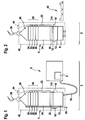
- Fig. 1 shows the schematic representation of a first embodiment of the dental device 2 according to the invention for the treatment by means of ultrasound.
- the device 2 can be subdivided essentially into two units, namely in an instrument 4 and a peripheral device 6.
- a power supply device 8 is provided which provides the necessary for the operation of the instrument 4 electrical energy.
- the instrument 4 is connected via a cable 10 to the peripheral device 6 and thus to the power supply device 8.
- the instrument 4 has a control device 12 for controlling the device 2.
- the control device 12 is integrated into the instrument 4, the handling of the device 2 according to the invention is greatly simplified and the size of the peripheral device 6 is reduced.
- the power supply device 8 supplies a transformer 14 with an electrical input voltage, which is indicated by the line 16.
- the transformer 14 is disposed directly on the instrument 4 and not in the peripheral device 6.
- the transformer 14 is a piezoelectric transformer 14.
- the piezoelectric transformer 14 comprises two planar piezoelectric elements stacked on top of each other, namely an input-side piezoelectric element 18 and an output-side piezoelectric element 20. While at the input-side piezoelectric element 18 - as described above - An electrical input voltage is applied, an electrical output voltage is tapped at the output-side piezoelectric element 20, as indicated by the line 22.
- the control device 12 decouples the piezoelectric elements 18, 20, 28, 30, 32, 34 by a corresponding wiring electrically against the supply network, since the oscillating piezoelectric elements always generate high-frequency voltages that could possibly disturb the supply network.
- the decoupling could also be provided in the power supply device 8.
- the input-side piezoelectric element 18 By the input-side piezoelectric element 18 is acted upon by the electrical input voltage, the electrical energy is converted into a mechanical energy, namely in a vibration of the input-side piezoelectric element 18, which expands and contracts alternately (piezoelectric effect).
- This mechanical energy now acts on the output side piezoelectric element 20, which is compressed accordingly or expands again. Due to this mechanical stress, electrical charges (inverse piezoelectric effect) are produced on the output-side piezoelectric element 20, so that an electrical output voltage can be tapped on the output-side piezoelectric element 20.
- the piezoelectric transformer 14 or its piezo elements 16, 18 are designed so that the electrical output voltage is higher than the electrical input voltage.
- the piezo elements 18, 20 are quartz components. Alternatively, the use of piezoceramics is conceivable.
- the piezoelectric transformer 14 is disposed on a resonance / flywheel 24, which consists for example of steel and is vibrated by a transducer 26 described below.
- the mass of the resonance / flywheel at the same time determines the resonant frequency of the oscillating system.
- the control device 12 could also be integrated into this resonance / flywheel mass 24 in order to achieve a further reduction of the instrument 4.
- the converter 26 provided on the instrument 4 adjoins the previously mentioned resonance / flywheel 24.
- the transducer 26 is a piezoelectric transducer 26, which in the present embodiment has a similar structure to the piezoelectric transformer 14 described above.
- the piezoelectric transducer 26 is composed of a plurality of layered planar piezoelectric elements together, in which case four piezoelectric elements 28, 30, 32, 34 are provided, which are quartz components.
- the electrical output voltage provided via the line 22, however, is converted into a mechanical ultrasonic vibration of each individual piezoelectric element 28, 30, 32, 34 of the transducer 26, which transmit to the resonance / flywheel 24 and a tool holder 36 becomes.
- a tool 38 is arranged, which is a tartar bit for the removal of tartar.
- the tool 38 has the classic hook-shaped shape of a tartar chisel and is interchangeably attached to the tool holder 36 so that the operator can replace the tool 38 according to the particular application or wear of the tool 38 and exchange the tool 38 when the patient changes can.
- the transmitted from the transducer 26 via the tool holder 36 on the tool 38 mechanical ultrasonic vibration leads to destruction the tartar as soon as the tool 38 comes into contact with it.
- a cooling device in the form of a liquid circuit 40 is provided, which absorbs the waste heat of the system, including the waste heat of the transformer by means of unillustrated heat exchanger and transported away.
- the resonance / flywheel 24 with all piezo elements of the excitation and the transformation, the control device 12 and the cooling 40 are housed in a housing 42, on the processing side still a light 44 is provided, which is connected to the low voltage part to the controller 12.
- Fig. 2 shows the schematic representation of a second embodiment of the dental device 40 according to the invention for the treatment by means of ultrasound.
- the second embodiment largely corresponds to the first embodiment, so that in the following only the differences from the first embodiment are shown and, moreover, should be made to the above description, wherein the same reference numerals have been used for similar components.
- the essential difference between the first device 2 and the second device 2 ' is that the energy supply device 8' in the second device 2 'in the instrument 4' is integrated. In this way, no cable 10 to supply the instrument 4 'more necessary, which simplifies its handling enormous.
- the peripheral device 6 can be completely eliminated.
- the energy supply device 8 ' may be energy storage, such as batteries or accumulators act. In the latter case it makes sense to have one provide separate charging device 40 through which the batteries can be recharged.
Abstract
Description
Die vorliegende Erfindung betrifft eine zahnärztliche Vorrichtung zur Behandlung mittels Ultraschall mit einem Transformator zur Umwandlung einer elektrischen Eingangsspannung in eine für höhere Leistungen erforderliche höhere elektrische Ausgangsspannung sowie ein Instrument, das einen Wandler zur Umwandlung der elektrischen Ausgangsspannung in eine mechanische Ultraschallschwingung aufweist.The present invention relates to a dental ultrasound treatment apparatus comprising a transformer for converting an input electrical voltage to a higher electrical output voltage required for higher powers, and an instrument having a converter for converting the electrical output voltage into a mechanical ultrasonic vibration.
Aus dem Stand der Technik sind unterschiedliche zahnärztliche Ultraschallgeräte bekannt, die beispielsweise der Entfernung von Zahnstein dienen. Die bekannten Vorrichtungen umfassen regelmäßig die folgenden Komponenten.Different dental ultrasonic devices are known from the prior art, which serve for example the removal of tartar. The known devices regularly comprise the following components.
Zum einen ist ein Transformator vorgesehen. Der Transformator dient der Umwandlung einer elektrischen Eingangsspannung in eine höhere elektrische Ausgangsspannung. Dies ist erforderlich, um eine höhere Abtragsleistung des Zahnsteinentferners o. Ä. zu erzielen. Die in herkömmlichen Geräten verwendeten Transformatoren beruhen auf dem elektromagnetischen Prinzip und bedürfen daher eines großen Aufbaus. Demzufolge sind die bekannten Transformatoren groß bzw. voluminös.First, a transformer is provided. The transformer is used to convert an electrical input voltage into a higher electrical output voltage. This is necessary to achieve a higher removal rate of the scaler or the like. to achieve. The transformers used in conventional devices are based on the electromagnetic principle and therefore require a large structure. As a result, the known transformers are large or voluminous.
Zum anderen weisen die bekannten Vorrichtungen ein Instrument auf, mit dem der Zahnarzt die zu behandelnden Stellen an den Zähnen bearbeitet. In das Handgerät ist ein Wandler integriert. Dieser Wandler dient der Umwandlung der elektrischen Ausgangsspannung in eine mechanische Ultraschallschwingung eines entsprechenden Werkzeuges. Derartige Wandler arbeiten herkömmlicherweise nach dem magnetostriktiven Prinzip oder dem piezoelektrischen Prinzip, wobei die magnetostriktiven Wandler eine geringere elektrische Ausgangsspannung benötigen als die piezoelektrischen Wandler.On the other hand, the known devices have an instrument with which the dentist works on the areas to be treated on the teeth. In the handset, a converter is integrated. This converter is used to convert the electrical output voltage into a mechanical ultrasonic vibration of a corresponding tool. Such transducers conventionally operate according to the magnetostrictive principle or the piezoelectric principle, wherein the magnetostrictive transducers require a lower electrical output voltage than the piezoelectric transducers.
Darüber hinaus umfassen die bekannten Vorrichtungen entsprechende Steuerungseinrichtungen zur Steuerung der Vorrichtung. Die bekannten Vorrichtungen sind dabei derart aufgebaut, dass der Transformator und die Steuerungseinrichtung in einem separaten Gerät untergebracht sind, um über ein Kabel bzw. eine Leitung mittelbar mit dem Instrument und dem darin angeordneten Wandler verbunden zu sein. Über das Kabel bzw. die Leitung erfolgt sowohl die Energieversorgung als auch die Übermittlung der Steuerbefehle von der Steuerungseinrichtung. Das die Steuerungseinrichtung und den Transformator aufnehmende Gerät muss im Behandlungsumfeld angeordnet werden und wird von der Bedienungsperson, wie beispielsweise dem Zahnarzt oder der Zahnarzthelferin, als störend empfunden, zumal dieses sehr voluminös ist, was die Handhabung nachhaltig erschwert.Moreover, the known devices comprise corresponding control devices for controlling the device. The known devices are constructed such that the transformer and the control device are housed in a separate device to be connected via a cable or a line indirectly with the instrument and the transducer arranged therein. Both the power supply and the transmission of the control commands from the control device takes place via the cable or the line. The control device and the transformer receiving device must be placed in the treatment environment and is perceived by the operator, such as the dentist or dental assistant, disturbing, especially since this is very bulky, which makes handling difficult.
Der vorliegenden Erfindung liegt somit die Aufgabe zugrunde, eine zahnärztliche Vorrichtung zur Behandlung mittels Ultraschall zu schaffen, die einen kompakten Aufbau bei gleichzeitig hoher Leistung hat und deren Handhabung vereinfacht ist.The present invention is therefore an object of the invention to provide a dental device for treatment by means of ultrasound, which has a compact design with high performance and their handling is simplified.
Die Lösung der vorgenannten Aufgabe erfolgt anhand der Merkmale des Patentanspruches 1. Vorteilhafte Ausführungsformen der Erfindung sind Gegenstand der Unteransprüche.The solution of the above object is based on the features of claim 1. Advantageous embodiments of the invention are the subject of the dependent claims.
Die erfindungsgemäße Vorrichtung ist eine zahnärztliche Vorrichtung zur Behandlung mittels Ultraschall. Es kann sich beispielsweise um eine Vorrichtung zum Entfernen von Zahnstein o. Ä. handeln. Die Vorrichtung weist einen Transformator auf. Der Transformator dient der Umwandlung einer elektrischen Eingangsspannung in eine für höhere Leistungen erforderliche höhere elektrische Ausgangsspannung. Als Transformator kommen beispielsweise herkömmliche, auf dem elektromagnetischen Prinzip beruhende Transformatoren in Frage.The device according to the invention is a dental device for treatment by means of ultrasound. It may be, for example, a device for removing Tartar or similar act. The device has a transformer. The transformer is used to convert an electrical input voltage into a higher electrical output voltage required for higher powers. As a transformer, for example, conventional, based on the electromagnetic principle transformers in question.
Die erfindungsgemäße Vorrichtung weist ferner ein Instrument auf, mit dem die Bearbeitung der zu behandelnden Stelle im Mund des Patienten erfolgt. Das Instrument ist mit einem Wandler versehen, der der Umwandlung der elektrischen Ausgangsspannung in eine mechanische Ultraschallschwingung dient. Als Wandler kommen beispielsweise magnetostriktive Wandler in Betracht, die aus dem Stand der Technik bekannt sind.The device according to the invention also has an instrument with which the treatment of the site to be treated takes place in the mouth of the patient. The instrument is provided with a transducer which converts the electrical output voltage into a mechanical ultrasonic vibration. Suitable converters are, for example, magnetostrictive converters which are known from the prior art.
Um einen kompakteren Aufbau der erfindungsgemäßen Vorrichtung zu erzielen, ist der Transformator unmittelbar an dem Instrument angeordnet. Unter Unmittelbarkeit ist hierbei u.a. zu verstehen, dass der Transformator nicht anderenorts aufgestellt ist, um mit dem Instrument über ein Kabel o. Ä. verbunden werden zu müssen. So kann der Transformator beispielsweise in das Instrument integriert sein. Auf diese Weise wird zwar das Instrument gegebenenfalls größer, jedoch ist dies weniger behindernd als ein großes externes Gerät, so dass eine leichtere Handhabbarkeit der gesamten Vorrichtung erzielt ist.In order to achieve a more compact construction of the device according to the invention, the transformer is arranged directly on the instrument. Under immediacy here u.a. to understand that the transformer is not placed elsewhere to the instrument via a cable o. Ä. to be connected. For example, the transformer can be integrated into the instrument. In this way, although the instrument may be larger, but this is less obstructive than a large external device, so that an easier handling of the entire device is achieved.
In einer besonders vorteilhaften Ausführungsform der erfindungsgemäßen zahnärztlichen Vorrichtung ist der Transformator ein piezoelektrischer Transformator. Ein derartiger piezoelektrischer Transformator besteht beispielsweise aus zwei Piezoelementen, wobei die elektrische Energie einenendes in mechanische Energie und anderenendes wieder in elektrische Energie gewandelt wird, wodurch die niedrige elektrische Eingangsspannung in eine erhöhte elektrische Ausgangsspannung umgewandelt werden kann. Auch kann dadurch ein hochfrequenterer Strom erzeugt werden. Der piezoelektrische Transformator hat den Vorteil, dass er im Vergleich zu den herkömmlichen gewickelten Transformatoren ein geringeres Gewicht und ein geringeres Volumen hat. Somit wird weder das Gewicht noch das Volumen des Instruments trotz der Einbindung des Transformators merklich vergrößert, was zu einer weiteren Verbesserung der Handhabung der erfindungsgemäßen Vorrichtung führt.In a particularly advantageous embodiment of the dental device according to the invention, the transformer is a piezoelectric transformer. Such a piezoelectric transformer, for example, consists of two piezoelectric elements, wherein the electrical energy end in a mechanical energy and the other again in electrical Energy is converted, whereby the low electrical input voltage can be converted into an increased electrical output voltage. Also, this can generate a high-frequency current. The piezoelectric transformer has the advantage that it has a lower weight and a smaller volume compared to the conventional wound transformers. Thus, neither the weight nor the volume of the instrument despite the involvement of the transformer is significantly increased, resulting in a further improvement in the handling of the device according to the invention.
In einer weiteren bevorzugten Ausführungsform der erfindungsgemäßen zahnärztlichen Vorrichtung ist der piezoelektrische Transformator an einer durch den Wandler in Schwingung versetzten Resonanz-/Schwungmasse angeordnet. Dies ermöglicht eine besonders kleine Bauweise des Instrumentes, wodurch die Handhabung der Vorrichtung weiter vereinfacht werden kann.In a further preferred embodiment of the dental device according to the invention, the piezoelectric transformer is arranged on a resonant / oscillating mass oscillated by the transducer. This allows a particularly small construction of the instrument, whereby the handling of the device can be further simplified.
In einer besonders bevorzugten Ausführungsform ist der piezoelektrische Transformator im Bereich eines Schwingungsbauchs der Resonanz-/Schwungmasse angeordnet. Die Resonanz-/Schwungmasse wird üblicherweise in einer Mode betrieben, die auch eine elastische Verformung der Resonanz-/Schwungmasse bewirkt. Dadurch entstehen entlang der Resonanz-/Schwungmasse mindestens ein Schwingungsknoten und zwei Schwingungsbäuche. Eine Anordnung in einem Schwingungsknoten würde den piezoelektrischen Transformator durch die in unterschiedliche Richtungen weisenden Beschleunigungen zur Erzeugung einer Wechselspannung mit der Schwingfrequenz der Resonanz-/Schwungmasse anregen. Einerseits würde dem schwingenden System dadurch Energie entzogen werden und andererseits würde eine Rückspeisung der hochfrequenten Wechselspannung entstehen, die herausgefiltert werden müsste.In a particularly preferred embodiment, the piezoelectric transformer is arranged in the region of a vibration antinode of the resonance / flywheel mass. The resonance / flywheel mass is usually operated in a mode which also causes elastic deformation of the resonance / flywheel mass. As a result, at least one vibration node and two antinodes arise along the resonance / flywheel mass. An arrangement in a vibration node would excite the piezoelectric transformer by the accelerations pointing in different directions to produce an alternating voltage with the oscillation frequency of the resonance / flywheel mass. On the one hand, this would deprive the oscillating system of energy and, on the other hand, would re-feed the high-frequency energy AC voltage arise that would have to be filtered out.
In einer alternativen besonders bevorzugten Ausführungsform ist der piezoelektrische Transformator mechanisch entkoppelt an der Resonanz-/Schwungmasse angeordnet. Damit lassen sich dieselben Vorteile wie bei einer Anordnung in einem Schwingungsbauch erzielen.In an alternative particularly preferred embodiment, the piezoelectric transformer is arranged mechanically decoupled on the resonance / flywheel mass. This can achieve the same advantages as with an arrangement in a vibration abdomen.
In einer weiteren vorteilhaften Ausführungsform der erfindungsgemäßen zahnärztlichen Vorrichtung ist der Wandler ein piezoelektrischer Wandler. Ein piezoelektrischer Wandler kann im Gegensatz zu den herkömmlicherweise eingesetzten magnetostriktiven Wandlern besonders klein und leichtgewichtig aufgebaut sein, was zu einem geringen Gewicht und zu einer geringen Größe des Instrumentes führt, wodurch wiederum die Handhabbarkeit der Vorrichtung verbessert ist.In a further advantageous embodiment of the dental device according to the invention, the transducer is a piezoelectric transducer. A piezoelectric transducer, in contrast to the magnetostrictive transducers conventionally used, can be made particularly small and lightweight, which results in a low weight and a small size of the instrument, which in turn improves the handling of the device.
Um eine besonders kleine Bauweise des Instrumentes zu ermöglichen, umfassen der piezoelektrische Transformator und/oder der piezoelektrische Wandler in einer besonders bevorzugten Ausführungsform der Erfindung mehrere übereinander geschichtete, ebene Piezoelemente.In order to allow a particularly small construction of the instrument, the piezoelectric transformer and / or the piezoelectric transducer in a particularly preferred embodiment of the invention comprise a plurality of planar piezo elements stacked one above the other.
In einer weiteren vorteilhaften Ausführungsform der erfindungsgemäßen zahnärztlichen Vorrichtung sind die Piezoelemente Quarz-, Turmalin- oder Seignettesalz-Bauelemente oder Piezokeramiken wie vorzugsweise PZT. Die piezoelektrischen Materialien sind somit natürliche Kristalle, die besonders gut hierfür geeignet sind.In a further advantageous embodiment of the dental device according to the invention, the piezo elements are quartz, tourmaline or Seignettesalz components or piezoceramics such as preferably PZT. The piezoelectric materials are thus natural crystals, which are particularly well suited for this purpose.
In einer weiteren bevorzugten Ausführungsform der erfindungsgemäßen Vorrichtung ist eine Steuerungseinrichtung, wie beispielsweise eine Steuerelektronik, zur Steuerung der Vorrichtung vorgesehen. Die Steuerungseinrichtung ist in das Instrument integriert. Die Steuerungseinrichtung kann neben der Elektronik auch entsprechende Bedienelemente umfassen, die fortan direkt an dem Instrument betätigt werden können. In jedem Fall kann die Größe des Beistellgerätes weiter verringert werden.In a further preferred embodiment of the device according to the invention, a control device, such as control electronics, is provided for controlling the device. The control device is integrated in the instrument. The control device can In addition to the electronics also include appropriate controls that can now be operated directly on the instrument. In any case, the size of the set-top box can be further reduced.
Vorteilhafterweise ist das Instrument von einem Gehäuse umfasst. In dem Gehäuse können alle Bauteile des Instruments untergebracht sein, die zur Erzeugung von Schwingenergie dienen.Advantageously, the instrument is comprised of a housing. In the housing all components of the instrument can be accommodated, which serve to generate vibration energy.
Gemäß einer weiteren vorteilhaften Ausführungsform der Erfindung ist eine Energieversorgungseinrichtung vorgesehen, die in das Gehäuse des Instruments integriert ist. Hierbei kann es sich beispielsweise um Akkumulatoren o. Ä. handeln. Da bei dieser Ausführungsform sowohl der Transformator als auch die Energieversorgungseinrichtung in das Gehäuse des Instruments integriert sind, kann das Instrument auch drahtlos betrieben werden, da weder die Steuersignale noch die notwendige Energie über ein Kabel übertragen werden müssten.According to a further advantageous embodiment of the invention, a power supply device is provided, which is integrated in the housing of the instrument. This may be, for example, accumulators o. Ä. act. Since in this embodiment both the transformer and the power supply device are integrated in the housing of the instrument, the instrument can also be operated wirelessly, since neither the control signals nor the necessary energy would have to be transmitted via a cable.
In einer weiteren bevorzugten Ausführungsform der erfindungsgemäßen zahnärztlichen Vorrichtung weist das Instrument ein Werkzeug auf, das durch den Wandler in mechanische Ultraschallschwingungen versetzt werden kann. Bei diesem Werkzeug kann es sich beispielsweise um einen Zahnsteinmeißel handeln, der hakenähnlich ausgebildet ist.In a further preferred embodiment of the dental device according to the invention, the instrument has a tool which can be set into mechanical ultrasonic vibrations by the transducer. This tool may be, for example, a tartar chisel, which is hook-like design.
In einer besonders bevorzugten Ausführungsform der erfindungsgemäßen zahnärztlichen Vorrichtung kann das an dem Instrument angeordnete Werkzeug ausgetauscht werden. Auf diese Weise muss bei einem Wechsel des Patienten lediglich das entsprechende Werkzeug ausgetauscht werden, um den bestehenden hygienischen Anforderungen zu genügen.In a particularly preferred embodiment of the dental device according to the invention, the tool arranged on the instrument can be exchanged. In this way, when changing the patient only the appropriate tool needs to be replaced to meet the existing hygienic requirements.
In einer bevorzugten Ausführungsform der zahnärztlichen Vorrichtung ist eine Lampe am Niederspannungsteil angeschlossen und in das Gehäuse integriert. Der Niederspannungsteil ist der Teil auf der Eingangsseite des Transformators. Die Spannung muss dann nicht erneut zum Betrieb der Lampe transformiert werden. Eine derartige Beleuchtung, die auf das Beahndlungsfeld gerichtet ist, sorgt für eine bessere Sicht.In a preferred embodiment of the dental device, a lamp is connected to the low voltage part and integrated into the housing. The low voltage part is the part on the input side of the transformer. The voltage then does not have to be transformed again to operate the lamp. Such lighting, which is directed to the Beahndlungsfeld, provides for a better view.
Eine besonders bevorzugte Ausführungsform der erfindungsgemäßen zahnärztlichen Vorrichtung sieht eine Einrichtung zur Kühlung des Instruments vor, wobei die Kühleinrichtung so ausgelegt ist, dass der Transformator durch die Kühleinrichtung mitgekühlt wird. Eine solche Kühleinrichtung dient bei Ultraschallinstrumenten häufig zur Kühlung des Werkzeugs und kann beispielsweise durch die Zu- und Ableitung von Wasser realisiert werden. Ein Transformator erzeugt prinzipbedingt immer Wärmeenergie, die durch eine solche Kühleinrichtung besonders leicht abgeführt werden kann.A particularly preferred embodiment of the dental device according to the invention provides a device for cooling the instrument, wherein the cooling device is designed so that the transformer is mitgekühlt by the cooling device. Such a cooling device is often used in ultrasonic instruments for cooling the tool and can be realized for example by the supply and discharge of water. As a matter of principle, a transformer always generates heat energy which can be removed particularly easily by such a cooling device.
- Fig. 1 zeigt die schematische Darstellung einer ersten Ausführungsform der erfindungsgemäßen zahnärztlichen Vorrichtung zur Behandlung mittels Ultraschall undFig. 1 shows the schematic representation of a first embodiment of the dental device according to the invention for the treatment by means of ultrasound and
- Fig. 2 zeigt die schematische Darstellung einer zweiten Ausführungsform der erfindungsgemäßen zahnärztlichen Vorrichtung zur Behandlung mittels Ultraschall.Fig. 2 shows the schematic representation of a second embodiment of the dental device according to the invention for the treatment by means of ultrasound.
Fig. 1 zeigt die schematische Darstellung einer ersten Ausführungsform der erfindungsgemäßen zahnärztlichen Vorrichtung 2 zur Behandlung mittels Ultraschall.Fig. 1 shows the schematic representation of a first embodiment of the
In der ersten Ausführungsform der Erfindung lässt sich die Vorrichtung 2 im Wesentlichen in zwei Einheiten unterteilen, nämlich in ein Instrument 4 und ein peripheres Gerät 6. In dem peripheren Gerät 6 ist eine Energieversorgungseinrichtung 8 vorgesehen, die die zum Betrieb des Instrumentes 4 notwendige elektrische Energie zur Verfügung stellt. Das Instrument 4 ist über ein Kabel 10 mit dem peripheren Gerät 6 und somit mit der Energieversorgungseinrichtung 8 verbunden.In the first embodiment of the invention, the
Das Instrument 4 weist eine Steuerungseinrichtung 12 zur Steuerung der Vorrichtung 2 auf. Indem die Steuerungseinrichtung 12 in das Instrument 4 integriert ist, wird die Handhabung der erfindungsgemäßen Vorrichtung 2 stark vereinfacht und die Größe des peripheren Gerätes 6 ist reduziert. Die Steuerungseinrichtung 12, die in der vorliegenden Ausführungsform von einer leistungsstarken Steuerelektronik gebildet wird, ist mit dem Kabel 10 verbunden.The instrument 4 has a
Über das Kabel 10 und die Steuerungseinrichtung 12 versorgt die Energieversorgungseinrichtung 8 einen Transformator 14 mit einer elektrischen Eingangsspannung, was anhand der Leitung 16 angedeutet ist. Der Transformator 14 ist unmittelbar an dem Instrument 4 und nicht in dem peripheren Gerät 6 angeordnet. Bei dem Transformator 14 handelt es sich um einen piezoelektrischen Transformator 14. Der piezoelektrische Transformator 14 umfasst in der vorliegenden Ausführungsform zwei übereinander geschichtete, ebene Piezoelemente, nämlich ein eingangsseitiges Piezoelement 18 und ein ausgangsseitiges Piezoelement 20. Während an das eingangsseitige Piezoelement 18 - wie zuvor beschrieben - eine elektrische Eingangsspannung angelegt wird, wird an dem ausgangsseitigen Piezoelement 20 eine elektrische Ausgangsspannung abgegriffen, wie dies anhand der Leitung 22 angedeutet ist.Via the
Die Steuerungseinrichtung 12 entkoppelt die Piezoelemente 18, 20, 28, 30, 32, 34 durch eine entsprechende Beschaltung elektrisch gegen das Versorgungsnetz, da die schwingenden Piezoelemente immer hochfrequente Spannungen erzeugen, die gegebenenfalls das Versorgungsnetz stören könnten.The
Die Entkopplung könnte auch in der Energieversorgungseinrichtung 8 vorgesehen sein.The decoupling could also be provided in the
Indem das eingangsseitige Piezoelement 18 mit der elektrischen Eingangsspannung beaufschlagt wird, wird die elektrische Energie in eine mechanische Energie umgewandelt, nämlich in eine Schwingung des eingangsseitigen Piezoelementes 18, das sich abwechselnd ausdehnt und wieder zusammenzieht (Piezoeffekt). Diese mechanische Energie wirkt nunmehr auf das ausgangsseitige Piezoelement 20, das entsprechend zusammengedrückt wird bzw. sich wieder ausdehnt. Auf Grund dieser mechanischen Beanspruchung entstehen auf dem ausgangsseitigen Piezoelement 20 elektrische Ladungen (inverser Piezoeffekt), so dass an dem ausgangsseitigen Piezoelement 20 eine elektrische Ausgangsspannung abgegriffen werden kann.By the input-side
Der piezoelektrische Transformator 14 bzw. dessen Piezoelemente 16, 18 sind so ausgelegt, dass die elektrische Ausgangsspannung höher als die elektrische Eingangsspannung ist. Bei den Piezoelementen 18, 20 handelt es sich um Quarz-Bauelemente. Alternativ ist der Einsatz von Piezokeramiken denkbar.The
Der piezoelektrische Transformator 14 ist an einer Resonanz-/Schwungmasse 24 angeordnet, die beispielsweise aus Stahl besteht und durch einen nachfolgend beschriebenen Wandler 26 in Schwingung versetzt wird. Die Masse der Resonanz-/Schwungmasse bestimmt gleichzeitig die Resonanzfrequenz des schwingenden Systems. Ergänzend sei angemerkt, dass die Steuerungseinrichtung 12 auch in diese Resonanz-/Schwungmasse 24 integriert sein könnte, um eine weitere Verkleinerung des Instrumentes 4 zu erreichen. Der an dem Instrument 4 vorgesehene Wandler 26 grenzt an die zuvor erwähnte Resonanz-/Schwungmasse 24 an. Bei dem Wandler 26 handelt es sich um einen piezoelektrischen Wandler 26, der in der vorliegenden Ausführungsform einen ähnlichen Aufbau wie der zuvor beschriebene piezoelektrische Transformator 14 hat. Auch der piezoelektrische Wandler 26 setzt sich aus mehreren übereinander geschichteten, ebenen Piezoelementen zusammen, wobei hier vier Piezoelemente 28, 30, 32, 34 vorgesehen sind, bei denen es sich um Quarz-Bauelemente handelt. Im Gegensatz zu dem Transformator 14 wird die über die Leitung 22 zur Verfügung gestellte elektrische Ausgangsspannung jedoch in eine mechanische Ultraschallschwingung jedes einzelnen Piezoelementes 28, 30, 32, 34 des Wandlers 26 umgewandelt, die auf die Resonanz-/Schwungmasse 24 und einen Werkzeughalter 36 übertragen wird.The
Andere Ausführungsformen mit mehr oder auch mit weniger Piezoelementen und/oder Piezoelementen aus Piezokeramik statt Quarz sind denkbar.Other embodiments with more or fewer piezo elements and / or piezo elements made of piezoceramic instead of quartz are conceivable.
An dem Werkzeughalter 36 ist ein Werkzeug 38 angeordnet, bei dem es sich um einen Zahnsteinmeißel zur Entfernung von Zahnstein handelt. Das Werkzeug 38 weist die klassische hakenförmige Gestalt eines Zahnsteinmeißels auf und ist austauschbar an dem Werkzeughalter 36 befestigt, so dass die Bedienungsperson das Werkzeug 38 entsprechend der jeweiligen Anwendung oder bei Verschleiß des Werkzeugs 38 austauschen und einen Austausch des Werkzeugs 38 bei einem Wechsel des Patienten durchführen kann. Die von dem Wandler 26 über den Werkzeughalter 36 auf das Werkzeug 38 übertragene mechanische Ultraschallschwingung führt zu einer Zerstörung des Zahnsteines, sobald das Werkzeug 38 mit diesem in Berührung kommt.At the
Zur Kühlung des Systems ist eine Kühlvorrichtung in Form einer Flüssigkeitskreislaufs 40 vorgesehen, der mittels nicht dargestellter Wärmetauscher die Abwärme des Systems einschließlich der Abwärme des Transformators aufnimmt und abtransportiert.For cooling the system, a cooling device in the form of a
Die Resonanz-/Schwungmasse 24 mit allen Piezoelementen der Anregung und der Transformation, die Steuerungseinrichtung 12 sowie die Kühlung 40 sind in einem Gehäuse 42 untergebracht, an dessen Bearbeitungsseite noch eine Leuchte 44 vorgesehen ist, die an den Niederspannungsteil an die Steuerungseinrichtung 12 angeschlossen ist.The resonance /
Fig. 2 zeigt die schematische Darstellung einer zweiten Ausführungsform der erfindungsgemäßen zahnärztlichen Vorrichtung 40 zur Behandlung mittels Ultraschall. Die zweite Ausführungsform entspricht weitgehend der ersten Ausführungsform, so dass im Folgenden lediglich die Unterschiede zu der ersten Ausführungsform dargestellt werden und im Übrigen auf die vorstehende Beschreibung verwiesen sein soll, wobei für gleichartige Komponenten die gleichen Bezugszeichen verwendet wurden.Fig. 2 shows the schematic representation of a second embodiment of the
Der wesentliche Unterschied zwischen der ersten Vorrichtung 2 und der zweiten Vorrichtung 2' besteht darin, dass die Energieversorgungseinrichtung 8' bei der zweiten Vorrichtung 2' in das Instrument 4' integriert ist. Auf diese Weise ist kein Kabel 10 zur Versorgung des Instrumentes 4' mehr erforderlich, was dessen Handhabung ungemein vereinfacht. Auch das periphere Gerät 6 kann vollständig entfallen. Bei der Energieversorgungseinrichtung 8' kann es sich um Energiespeicher, wie beispielsweise Batterien oder Akkumulatoren, handeln. Im letzteren Fall ist es sinnvoll, eine separate Ladeeinrichtung 40 vorzusehen, über die die Akkumulatoren wieder aufgeladen werden können.The essential difference between the
Claims (10)
Applications Claiming Priority (1)
| Application Number | Priority Date | Filing Date | Title |
|---|---|---|---|
| DE102005010556A DE102005010556B4 (en) | 2005-03-04 | 2005-03-04 | Dental device for treatment by means of ultrasound |
Publications (2)
| Publication Number | Publication Date |
|---|---|
| EP1698301A1 true EP1698301A1 (en) | 2006-09-06 |
| EP1698301B1 EP1698301B1 (en) | 2011-10-12 |
Family
ID=36540226
Family Applications (1)
| Application Number | Title | Priority Date | Filing Date |
|---|---|---|---|
| EP06110682A Active EP1698301B1 (en) | 2005-03-04 | 2006-03-06 | Dental device for ultrasound treatment |
Country Status (3)
| Country | Link |
|---|---|
| EP (1) | EP1698301B1 (en) |
| AT (1) | ATE527962T1 (en) |
| DE (1) | DE102005010556B4 (en) |
Cited By (3)
| Publication number | Priority date | Publication date | Assignee | Title |
|---|---|---|---|---|
| EP2055257A2 (en) | 2007-11-02 | 2009-05-06 | VOCO GmbH | Vibrating application brush |
| CN104758072A (en) * | 2015-04-27 | 2015-07-08 | 桂林市啄木鸟医疗器械有限公司 | Constant power output circuit and ultrasonic tooth cleaner constant power control method |
| CN104215203B (en) * | 2014-08-19 | 2017-03-15 | 上海交通大学 | A kind of deformation of transformer winding online test method and system based on ultrasonic wave |
Citations (6)
| Publication number | Priority date | Publication date | Assignee | Title |
|---|---|---|---|---|
| US4012647A (en) * | 1974-01-31 | 1977-03-15 | Ultrasonic Systems, Inc. | Ultrasonic motors and converters |
| US4038571A (en) * | 1974-01-03 | 1977-07-26 | Litton Industrial Products, Inc. | Piezoelectric dental cleaning device |
| US5309590A (en) * | 1990-12-13 | 1994-05-10 | Gemtech, Inc. | Dentifrice/medication dispensing toothbrush |
| EP0914809A1 (en) * | 1997-11-10 | 1999-05-12 | Mectron di Bianchetti Fernando e Vercellotti Domenico S.N.C. | Dental hand instrument with incorporated light source for diagnostics purposes |
| US6139320A (en) * | 1994-02-27 | 2000-10-31 | Hahn; Rainer | Apparatus, method and expedient materials for ultrasonic preparation of human and animal hard or soft tissues and of dental or bone replacement materials as well as object obtained thereby |
| US20020138090A1 (en) * | 2001-03-26 | 2002-09-26 | Jewett Warren R. | Ultrasonic scalpel |
Family Cites Families (6)
| Publication number | Priority date | Publication date | Assignee | Title |
|---|---|---|---|---|
| US3518766A (en) * | 1969-01-30 | 1970-07-07 | Emanuel Burt | Piezoelectric cleaning device with removable workpiece |
| DE2219657B2 (en) * | 1972-04-21 | 1974-04-25 | Siemens Ag, 1000 Berlin U. 8000 Muenchen | Dental handpiece |
| DE8507777U1 (en) * | 1985-03-15 | 1985-05-09 | Siemens AG, 1000 Berlin und 8000 München | Dental ultrasonic handpiece |
| DE3706934A1 (en) * | 1987-03-04 | 1988-09-15 | Medtronic Medizinisch Elektron | Dental hand-held ultrasound instrument |
| DE29504619U1 (en) * | 1995-03-17 | 1995-07-27 | Breiter Ulrich | Ultrasound device for removing plaque |
| IT1296088B1 (en) * | 1997-11-10 | 1999-06-09 | Mectron Di Bianchetti Fernando | DENTAL HANDPIECE WITH BUILT-IN LIGHT SOURCE |
-
2005
- 2005-03-04 DE DE102005010556A patent/DE102005010556B4/en not_active Expired - Fee Related
-
2006
- 2006-03-06 AT AT06110682T patent/ATE527962T1/en active
- 2006-03-06 EP EP06110682A patent/EP1698301B1/en active Active
Patent Citations (6)
| Publication number | Priority date | Publication date | Assignee | Title |
|---|---|---|---|---|
| US4038571A (en) * | 1974-01-03 | 1977-07-26 | Litton Industrial Products, Inc. | Piezoelectric dental cleaning device |
| US4012647A (en) * | 1974-01-31 | 1977-03-15 | Ultrasonic Systems, Inc. | Ultrasonic motors and converters |
| US5309590A (en) * | 1990-12-13 | 1994-05-10 | Gemtech, Inc. | Dentifrice/medication dispensing toothbrush |
| US6139320A (en) * | 1994-02-27 | 2000-10-31 | Hahn; Rainer | Apparatus, method and expedient materials for ultrasonic preparation of human and animal hard or soft tissues and of dental or bone replacement materials as well as object obtained thereby |
| EP0914809A1 (en) * | 1997-11-10 | 1999-05-12 | Mectron di Bianchetti Fernando e Vercellotti Domenico S.N.C. | Dental hand instrument with incorporated light source for diagnostics purposes |
| US20020138090A1 (en) * | 2001-03-26 | 2002-09-26 | Jewett Warren R. | Ultrasonic scalpel |
Cited By (4)
| Publication number | Priority date | Publication date | Assignee | Title |
|---|---|---|---|---|
| EP2055257A2 (en) | 2007-11-02 | 2009-05-06 | VOCO GmbH | Vibrating application brush |
| DE102007052442A1 (en) | 2007-11-02 | 2009-05-07 | Voco Gmbh | Vibrating application brush |
| CN104215203B (en) * | 2014-08-19 | 2017-03-15 | 上海交通大学 | A kind of deformation of transformer winding online test method and system based on ultrasonic wave |
| CN104758072A (en) * | 2015-04-27 | 2015-07-08 | 桂林市啄木鸟医疗器械有限公司 | Constant power output circuit and ultrasonic tooth cleaner constant power control method |
Also Published As
| Publication number | Publication date |
|---|---|
| EP1698301B1 (en) | 2011-10-12 |
| DE102005010556B4 (en) | 2007-05-24 |
| ATE527962T1 (en) | 2011-10-15 |
| DE102005010556A1 (en) | 2006-09-07 |
Similar Documents
| Publication | Publication Date | Title |
|---|---|---|
| DE102009013034B4 (en) | Autoclavable charging device for an energy store of a surgical instrument and method for charging a rechargeable energy store in an autoclaved surgical instrument or for an autoclaved surgical instrument | |
| DE60205788T2 (en) | Ultrasonic device for cosmetic treatment | |
| EP0857088A1 (en) | Device for transferring ultrasonic energy into a liquid or pasty medium | |
| EP2490863B1 (en) | Electric power tool with ultrasonic excitation | |
| DE3826414A1 (en) | ULTRASONIC THERAPY DEVICE | |
| EP2644320A1 (en) | Handheld electric power tool | |
| WO1991007917A2 (en) | Ultrasonic surgical instrument | |
| EP1698301B1 (en) | Dental device for ultrasound treatment | |
| DE3833342A1 (en) | Piezoelectric motor | |
| DE112015007231T5 (en) | ultrasound transducer | |
| DE2752437C2 (en) | ||
| DE1488698A1 (en) | Electric drive device, in particular drive device for a small mechanical payload | |
| EP2003709B1 (en) | Piezo converter with primary automatic control and pertinent piezo transformer | |
| WO2016029326A1 (en) | Measuring device for characterising a test piece using ultrasonic transverse waves and longitudinal waves | |
| DE1812526A1 (en) | Method and device for turning screw connections | |
| DE3032022C2 (en) | Vibration device for denture care | |
| EP0340422A2 (en) | Apparatus for dissolving concretions in a body cavity | |
| DE4436812B4 (en) | driving device | |
| WO2002087459A2 (en) | Handpiece for linear actuation of a tool, preferably a dental tool | |
| DE60222610T2 (en) | Improved system and method for monitoring vibrations | |
| DE2219657B2 (en) | Dental handpiece | |
| DE102004022663A1 (en) | Electric toothbrush has brush head with bristles which are vibrated by vibration motor depending on contact pressure of bristles against teeth | |
| DE2219761A1 (en) | DENTAL HANDPIECE | |
| EP4341010A1 (en) | Ultrasonic generator for feeding electrical power for fragmenting calculi, lithotripsy device, lithotripsy system and method for identifying a sonotrode | |
| DE102006016359B4 (en) | Method for controlling an ultrasonic unit of an ultrasonic cleaning system and ultrasonic cleaning system |
Legal Events
| Date | Code | Title | Description |
|---|---|---|---|
| PUAI | Public reference made under article 153(3) epc to a published international application that has entered the european phase |
Free format text: ORIGINAL CODE: 0009012 |
|
| AK | Designated contracting states |
Kind code of ref document: A1 Designated state(s): AT BE BG CH CY CZ DE DK EE ES FI FR GB GR HU IE IS IT LI LT LU LV MC NL PL PT RO SE SI SK TR |
|
| AX | Request for extension of the european patent |
Extension state: AL BA HR MK YU |
|
| 17P | Request for examination filed |
Effective date: 20070301 |
|
| AKX | Designation fees paid |
Designated state(s): AT BE BG CH CY CZ DE DK EE ES FI FR GB GR HU IE IS IT LI LT LU LV MC NL PL PT RO SE SI SK TR |
|
| GRAP | Despatch of communication of intention to grant a patent |
Free format text: ORIGINAL CODE: EPIDOSNIGR1 |
|
| GRAS | Grant fee paid |
Free format text: ORIGINAL CODE: EPIDOSNIGR3 |
|
| GRAA | (expected) grant |
Free format text: ORIGINAL CODE: 0009210 |
|
| AK | Designated contracting states |
Kind code of ref document: B1 Designated state(s): AT BE BG CH CY CZ DE DK EE ES FI FR GB GR HU IE IS IT LI LT LU LV MC NL PL PT RO SE SI SK TR |
|
| REG | Reference to a national code |
Ref country code: GB Ref legal event code: FG4D Free format text: NOT ENGLISH |
|
| REG | Reference to a national code |
Ref country code: CH Ref legal event code: EP |
|
| REG | Reference to a national code |
Ref country code: IE Ref legal event code: FG4D |
|
| REG | Reference to a national code |
Ref country code: DE Ref legal event code: R096 Ref document number: 502006010381 Country of ref document: DE Effective date: 20111215 |
|
| REG | Reference to a national code |
Ref country code: NL Ref legal event code: VDEP Effective date: 20111012 |
|
| LTIE | Lt: invalidation of european patent or patent extension |
Effective date: 20111012 |
|
| PG25 | Lapsed in a contracting state [announced via postgrant information from national office to epo] |
Ref country code: IS Free format text: LAPSE BECAUSE OF FAILURE TO SUBMIT A TRANSLATION OF THE DESCRIPTION OR TO PAY THE FEE WITHIN THE PRESCRIBED TIME-LIMIT Effective date: 20120212 Ref country code: LT Free format text: LAPSE BECAUSE OF FAILURE TO SUBMIT A TRANSLATION OF THE DESCRIPTION OR TO PAY THE FEE WITHIN THE PRESCRIBED TIME-LIMIT Effective date: 20111012 |
|
| REG | Reference to a national code |
Ref country code: IE Ref legal event code: FD4D |
|
| PG25 | Lapsed in a contracting state [announced via postgrant information from national office to epo] |
Ref country code: GR Free format text: LAPSE BECAUSE OF FAILURE TO SUBMIT A TRANSLATION OF THE DESCRIPTION OR TO PAY THE FEE WITHIN THE PRESCRIBED TIME-LIMIT Effective date: 20120113 Ref country code: SI Free format text: LAPSE BECAUSE OF FAILURE TO SUBMIT A TRANSLATION OF THE DESCRIPTION OR TO PAY THE FEE WITHIN THE PRESCRIBED TIME-LIMIT Effective date: 20111012 Ref country code: NL Free format text: LAPSE BECAUSE OF FAILURE TO SUBMIT A TRANSLATION OF THE DESCRIPTION OR TO PAY THE FEE WITHIN THE PRESCRIBED TIME-LIMIT Effective date: 20111012 Ref country code: PT Free format text: LAPSE BECAUSE OF FAILURE TO SUBMIT A TRANSLATION OF THE DESCRIPTION OR TO PAY THE FEE WITHIN THE PRESCRIBED TIME-LIMIT Effective date: 20120213 Ref country code: LV Free format text: LAPSE BECAUSE OF FAILURE TO SUBMIT A TRANSLATION OF THE DESCRIPTION OR TO PAY THE FEE WITHIN THE PRESCRIBED TIME-LIMIT Effective date: 20111012 Ref country code: SE Free format text: LAPSE BECAUSE OF FAILURE TO SUBMIT A TRANSLATION OF THE DESCRIPTION OR TO PAY THE FEE WITHIN THE PRESCRIBED TIME-LIMIT Effective date: 20111012 |
|
| PG25 | Lapsed in a contracting state [announced via postgrant information from national office to epo] |
Ref country code: CY Free format text: LAPSE BECAUSE OF FAILURE TO SUBMIT A TRANSLATION OF THE DESCRIPTION OR TO PAY THE FEE WITHIN THE PRESCRIBED TIME-LIMIT Effective date: 20111012 |
|
| PG25 | Lapsed in a contracting state [announced via postgrant information from national office to epo] |
Ref country code: DK Free format text: LAPSE BECAUSE OF FAILURE TO SUBMIT A TRANSLATION OF THE DESCRIPTION OR TO PAY THE FEE WITHIN THE PRESCRIBED TIME-LIMIT Effective date: 20111012 Ref country code: SK Free format text: LAPSE BECAUSE OF FAILURE TO SUBMIT A TRANSLATION OF THE DESCRIPTION OR TO PAY THE FEE WITHIN THE PRESCRIBED TIME-LIMIT Effective date: 20111012 Ref country code: IE Free format text: LAPSE BECAUSE OF FAILURE TO SUBMIT A TRANSLATION OF THE DESCRIPTION OR TO PAY THE FEE WITHIN THE PRESCRIBED TIME-LIMIT Effective date: 20111012 Ref country code: BG Free format text: LAPSE BECAUSE OF FAILURE TO SUBMIT A TRANSLATION OF THE DESCRIPTION OR TO PAY THE FEE WITHIN THE PRESCRIBED TIME-LIMIT Effective date: 20120112 Ref country code: EE Free format text: LAPSE BECAUSE OF FAILURE TO SUBMIT A TRANSLATION OF THE DESCRIPTION OR TO PAY THE FEE WITHIN THE PRESCRIBED TIME-LIMIT Effective date: 20111012 Ref country code: CZ Free format text: LAPSE BECAUSE OF FAILURE TO SUBMIT A TRANSLATION OF THE DESCRIPTION OR TO PAY THE FEE WITHIN THE PRESCRIBED TIME-LIMIT Effective date: 20111012 |
|
| PLBE | No opposition filed within time limit |
Free format text: ORIGINAL CODE: 0009261 |
|
| STAA | Information on the status of an ep patent application or granted ep patent |
Free format text: STATUS: NO OPPOSITION FILED WITHIN TIME LIMIT |
|
| PG25 | Lapsed in a contracting state [announced via postgrant information from national office to epo] |
Ref country code: RO Free format text: LAPSE BECAUSE OF FAILURE TO SUBMIT A TRANSLATION OF THE DESCRIPTION OR TO PAY THE FEE WITHIN THE PRESCRIBED TIME-LIMIT Effective date: 20111012 Ref country code: PL Free format text: LAPSE BECAUSE OF FAILURE TO SUBMIT A TRANSLATION OF THE DESCRIPTION OR TO PAY THE FEE WITHIN THE PRESCRIBED TIME-LIMIT Effective date: 20111012 |
|
| 26N | No opposition filed |
Effective date: 20120713 |
|
| BERE | Be: lapsed |
Owner name: SIRONA DENTAL SYSTEMS G.M.B.H. Effective date: 20120331 |
|
| PG25 | Lapsed in a contracting state [announced via postgrant information from national office to epo] |
Ref country code: MC Free format text: LAPSE BECAUSE OF NON-PAYMENT OF DUE FEES Effective date: 20120331 |
|
| REG | Reference to a national code |
Ref country code: DE Ref legal event code: R097 Ref document number: 502006010381 Country of ref document: DE Effective date: 20120713 |
|
| GBPC | Gb: european patent ceased through non-payment of renewal fee |
Effective date: 20120306 |
|
| PG25 | Lapsed in a contracting state [announced via postgrant information from national office to epo] |
Ref country code: BE Free format text: LAPSE BECAUSE OF NON-PAYMENT OF DUE FEES Effective date: 20120331 Ref country code: GB Free format text: LAPSE BECAUSE OF NON-PAYMENT OF DUE FEES Effective date: 20120306 |
|
| PG25 | Lapsed in a contracting state [announced via postgrant information from national office to epo] |
Ref country code: ES Free format text: LAPSE BECAUSE OF FAILURE TO SUBMIT A TRANSLATION OF THE DESCRIPTION OR TO PAY THE FEE WITHIN THE PRESCRIBED TIME-LIMIT Effective date: 20120123 |
|
| PG25 | Lapsed in a contracting state [announced via postgrant information from national office to epo] |
Ref country code: FI Free format text: LAPSE BECAUSE OF FAILURE TO SUBMIT A TRANSLATION OF THE DESCRIPTION OR TO PAY THE FEE WITHIN THE PRESCRIBED TIME-LIMIT Effective date: 20111012 |
|
| PG25 | Lapsed in a contracting state [announced via postgrant information from national office to epo] |
Ref country code: TR Free format text: LAPSE BECAUSE OF FAILURE TO SUBMIT A TRANSLATION OF THE DESCRIPTION OR TO PAY THE FEE WITHIN THE PRESCRIBED TIME-LIMIT Effective date: 20111012 |
|
| PG25 | Lapsed in a contracting state [announced via postgrant information from national office to epo] |
Ref country code: LU Free format text: LAPSE BECAUSE OF NON-PAYMENT OF DUE FEES Effective date: 20120306 |
|
| PG25 | Lapsed in a contracting state [announced via postgrant information from national office to epo] |
Ref country code: HU Free format text: LAPSE BECAUSE OF FAILURE TO SUBMIT A TRANSLATION OF THE DESCRIPTION OR TO PAY THE FEE WITHIN THE PRESCRIBED TIME-LIMIT Effective date: 20060306 |
|
| REG | Reference to a national code |
Ref country code: FR Ref legal event code: PLFP Year of fee payment: 11 |
|
| REG | Reference to a national code |
Ref country code: FR Ref legal event code: PLFP Year of fee payment: 12 |
|
| REG | Reference to a national code |
Ref country code: FR Ref legal event code: PLFP Year of fee payment: 13 |
|
| REG | Reference to a national code |
Ref country code: DE Ref legal event code: R082 Ref document number: 502006010381 Country of ref document: DE |
|
| PGFP | Annual fee paid to national office [announced via postgrant information from national office to epo] |
Ref country code: FR Payment date: 20230208 Year of fee payment: 18 Ref country code: AT Payment date: 20230227 Year of fee payment: 18 |
|
| PGFP | Annual fee paid to national office [announced via postgrant information from national office to epo] |
Ref country code: IT Payment date: 20230213 Year of fee payment: 18 Ref country code: DE Payment date: 20230131 Year of fee payment: 18 |
|
| PGFP | Annual fee paid to national office [announced via postgrant information from national office to epo] |
Ref country code: CH Payment date: 20230402 Year of fee payment: 18 |