EP1743547A1 - Improved interdental brush device with sliding cap - Google Patents
Improved interdental brush device with sliding cap Download PDFInfo
- Publication number
- EP1743547A1 EP1743547A1 EP06117059A EP06117059A EP1743547A1 EP 1743547 A1 EP1743547 A1 EP 1743547A1 EP 06117059 A EP06117059 A EP 06117059A EP 06117059 A EP06117059 A EP 06117059A EP 1743547 A1 EP1743547 A1 EP 1743547A1
- Authority
- EP
- European Patent Office
- Prior art keywords
- cap
- support
- interdental brush
- opening
- pin
- Prior art date
- Legal status (The legal status is an assumption and is not a legal conclusion. Google has not performed a legal analysis and makes no representation as to the accuracy of the status listed.)
- Granted
Links
- 230000003247 decreasing effect Effects 0.000 claims description 2
- 230000001747 exhibiting effect Effects 0.000 claims description 2
- 230000000717 retained effect Effects 0.000 description 1
- 230000003313 weakening effect Effects 0.000 description 1
Images

Classifications
-
- A—HUMAN NECESSITIES
- A61—MEDICAL OR VETERINARY SCIENCE; HYGIENE
- A61C—DENTISTRY; APPARATUS OR METHODS FOR ORAL OR DENTAL HYGIENE
- A61C15/00—Devices for cleaning between the teeth
-
- A—HUMAN NECESSITIES
- A46—BRUSHWARE
- A46B—BRUSHES
- A46B7/00—Bristle carriers arranged in the brush body
- A46B7/04—Bristle carriers arranged in the brush body interchangeably removable bristle carriers
-
- A—HUMAN NECESSITIES
- A46—BRUSHWARE
- A46B—BRUSHES
- A46B2200/00—Brushes characterized by their functions, uses or applications
- A46B2200/10—For human or animal care
- A46B2200/1066—Toothbrush for cleaning the teeth or dentures
- A46B2200/108—Inter-dental toothbrush, i.e. for cleaning interdental spaces specifically
Landscapes
- Health & Medical Sciences (AREA)
- Dentistry (AREA)
- Epidemiology (AREA)
- Life Sciences & Earth Sciences (AREA)
- Animal Behavior & Ethology (AREA)
- General Health & Medical Sciences (AREA)
- Public Health (AREA)
- Veterinary Medicine (AREA)
- Brushes (AREA)
Abstract
Description
- The present invention concerns an interdental brush device, in particular a device equipped with a sliding cap.
- A known interdental brush, which proved particularly effective, is the one shown in
EP537663 - This device consists of a handle support, at the end whereof a transversal through-hole and a sliding cap are provided. The cap has two elongated openings, a front one and a rear one, through which the deformable stem of the replaceable brush is introduced, which is then folded down and retained on the support. The front opening - i.e. on the side from which the brush projects - also defines the upper and lower end-stop of the cap, since the shorter sides thereof are intended to come into abutment with a small projecting pin coaxial with the transversal hole for brush introduction.
- The cross section of the cap and, consequently, of the support end, is substantially rectangular.
- This specific configuration, as well as the dimensioning adopted so far, have required to provide a flexible flap on the front side, on the edge of the elongated opening, the deformation whereof allows to fit the cap on the support upon assembling the device, introducing said cap from the end thereof, despite the presence of the projecting pin.
- This flap is defined as a portion of the cap wall limited by two parallel slits.
- However, it has been detected that this configuration may be improved, since flap flexibility also tends to allow full cap removal if the user applies excessive traction on the cap pulling in an opposite direction to the support end. Moreover, the presence of two slits to the sides of the flap represents possible starting points for cracks which end up breaking the cap.
- For both safety and practical reasons, it is instead desired to provide an interdental brush wherein the cap may still be fitted introducing the same from the support end, but may not be easily removed, not even applying considerable traction. Moreover, it is desired to provide a cap which, in order to be fitted, does not necessarily require the presence of a flexible flap equipped with side slits, which ends up weakening the cap structure.
- Such object is perfectly achieved by a device as described in its essential features in the accompanying main claim, i.e. a device with an interdental brush of the type comprising a support end, provided with a transversal hole capable of housing a deformable stem of a replaceable interdental brush, onto which a cap may be fitted, slidable between two end-stop positions determined by the abutment of a first opening thereof with a pin projecting coaxially with said transversal hole, the cap further exhibiting a second opening opposite to the first one allowing said deformable stem to pass through, the end of said support having a curved back profile connecting with the top end of said support and the cross-section profile of said support end being rounded at least on its back side.
- According to another aspect of the invention, said portion connecting the back profile with the top end of the support has a curvature radius gently decreasing towards the top end from about 25 cm to about 2 cm.
- According to a further aspect, the cap has a base segment, between a mouth rim thereof and the proximal edge of the first opening, over 5mm, preferably over 7 mm, long. Preferably, the cross-section of said support end is D-shaped with rounded-off edges.
- Further features and advantages of the interdental brush according to the invention will in any case be more evident from the following detailed description, given by way of example and illustrated in the accompanying drawings, wherein:
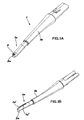
- fig. 1A is a perspective view, from the right front side, of a preferred embodiment of the support of the invention;
- fig. 1B is a similar view to that of fig. 1A taken from the rear left side;
- fig. 2A is a view of the cap according to the invention taken according to the perspective of fig. 1A;
- fig. 2B is a view of the cap according to the invention taken according to the perspective of fig. 1B;
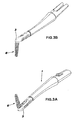
- figs. 3A and 3B are similar views of the interdental brush according to the present invention in a full embodiment;
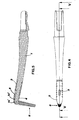
- fig. 4 is a rear elevation view of the device of figs. 3A and 3B;
- fig. 5 is a cross-section view taken along line V-V of fig. 4; and
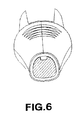
- fig. 6 is a cross-section view of the cap portion according to the invention.
- In the following description, reference will be made to an interdental brush device wherein the support portion may be disengaged from a handle portion. This particular embodiment must not be intended as a limiting one, since the same teachings offered here may be applied to a support integral with the handle. In any case, the handle portion and the engaging elements will not be described here in further detail because they do not form the subject of the present application.
- As shown in figs. 1A and 1B, a support 1 of an interdental brush is formed as an elongated body, for example moulded of a plastic material, at the end whereof a through-
hole 2 is provided lying transversally to the main axis of the support.Hole 2 is obtained coaxially to apin 2a which projects transversally from the end portion. - A significant length of the
end portion 1a is advantageously of a smaller section than theremaining neck part 1b, allowing to house a cap capable of being flush with the support main portion. - As can be appreciated, in particular from fig. 6, according to the invention at least
end portion 1a has a substantially D-shaped cross-section, in particular with a wide curvature on its rear or back side (the one visible in fig. 1B) and a substantially flat front side (fig. 1A), connected with the rear side. This shape is particularly advantageous for the reasons highlighted here below. - Moreover, according to the invention, the
top portion 1a' of support end 1 has a back profile - i.e. the one on the side opposite to the front side from wherepin 2a projects - which gently curves down towardspin 2a, as is well visible in figs. 1B and 5. Although the curvature of this area may well be defined through a "spline", it may be exemplarily approximated as having a curvature radius which, for example, is initially 25 cm, then about 8 cm and finally, at its point of connection withpin 2a, about 2 cm. - Along the back line of such profile, a
groove 1a'' is further provided, intended to house the deformable stem of a replaceable interdental brush, as will be shown further down. - On the
end portion 1a of the support, as already mentioned, a cap 3 - clearly shown in figs. 2A and 2B - is intended to be fitted. The cap is shaped as a hollow body, with an opening 3a in correspondence of the base thereof, and has an inner surface which matches the one of theend portion 1a of support 1 and allows longitudinal sliding thereof. - On the front side of
cap 3, said cap has anaperture 4 flaring out at its ends into two round-shaped eyes pin 2a. Thereby,cap 3 may slide between two end-stop positions determined by the engagement of eacheye pin 2a. Therefore, the distance between the centres of these two round-shaped eyes cap 3. - On the back side the cap has a
second opening 5, suitable for the stem of the replaceable interdental brush to run across in a manner known per se. -
Cap 3 has an overall length of about 20 mm; advantageously, the length of the base portion, i.e. the distance between themouth 3a and the eye of inner end-stop 4b, is about 8 mm, in any case above 7 mm. This feature causes the base portion ofcap 3 to offer a significant resistance to deformation and flexure: this makes it very unlikely, given the clearance existing between the cap and theend portion 1a of the support, for the edge ofinner eye 4b to rise overpin 2a - for example due to excessive traction - and hence forcap 3 to accidentally slide off the support. - Conversely, the
rounded top 1a' of the support defines a bevel sufficient to allow to easily fitcap 3 on theend portion 1a, despite the presence ofpin 2a. As a matter of fact, thanks to the bevel of rounded offprofile 1a', the edge of the base rim of the cap may be brought up to abovepin 2a, the subsequent thrust causing a local deformation ofcap 3, which ends up sliding into its operating position with the pin between the twoeyes end portion 1a of the support: as a matter of fact, the curved back of the D-section of the same cap is intended to slide on thebevelled profile 1a' of the support top, resulting in a wide gap or initial clearance betweencap 3 and support 1, which improves deformability of the former and hence an easy fitting of the same. - As already mentioned, the opposite process - i.e. removal of the cap - is instead prevented by the fact that no bevel exists allowing the edge of
inner eye 4b to overcomepin 2a. - Thereby, a better guarantee over the prior art that
cap 3 may not be accidentally removed is provided. - In figs. 3A, 3B, 4 and 5 a support 1 is shown assembled with its
cap 3 in an operating position. It should be appreciated that the assembly is also equipped with aninterdental brush 6, whose deformable stem (for example a double twisted wire) has been introduced intohole 2 whilecap 3 was in its outer end-stop position - i.e. witheye 4b engaged withpin 2a andopening 5 in correspondence of hole 2 - end it has then been folded back and steadily housed ingroove 1a'', moving the cap into the inner end-stop position - witheye 4a in correspondence of pin 2 (position of figs. 4 and 5). - The interdental brush support according to the invention fully achieves the objects set forth in the preliminary remarks, since it offers a structure which is much more efficient over the prior art to be able to comfortably fit the cap and avoid any accidental disengagement, thereby contributing to pleasantness and safety of use for the end user.
- However, it is understood that protection of the invention described above is not limited to the particular embodiment shown, but extends to any other equivalent embodiment.
- In particular, as already mentioned, the interdental brush support may be manufactured integrally with a corresponding handle, rather than as two engageable components.
- Moreover, despite what has been shown in the drawings in an exemplificative way (figs. 2A and 3A), thanks to the innovative configuration offered here, it is no longer necessary for the cap to be equipped with a flexible flap and side slits.
Claims (4)
- Device with an interdental brush of the type comprising a support end, provided with a transversal hole (2) capable of housing a deformable stem of a replaceable interdental brush, onto which a cap (3) may be fitted, slidable between two end-stop positions determined by the abutment of a first opening (4, 4a, 4b) thereof with a pin (2a) projecting coaxially with said transversal hole (2), the cap (3) further exhibiting a second opening (5) opposite to the first one allowing said deformable stem to pass through,
characterised in that the end of said support has a curved back profile with a portion connecting with the top end of said support, and in that the cross-section profile of said support end is rounded at least on its back side. - Device as in claim 1), wherein said connecting portion has a curvature radius decreasing towards the top end from about 25 cm to about 2 cm.
- Device as in claim 1) or 2), wherein said cap (3) has a base segment, between a mouth rim (3a) thereof and the proximal edge (4b) of said first opening (4), over 5 mm long.
- Device as in any one of the preceding claims, wherein the cross-section of said support end is D-shaped with rounded-off edges.
Applications Claiming Priority (1)
| Application Number | Priority Date | Filing Date | Title |
|---|---|---|---|
| IT000258U ITMI20050258U1 (en) | 2005-07-14 | 2005-07-14 | PERFECTED INTERDENTAL BRUSH DEVICE WITH SLIDING HOOD |
Publications (2)
| Publication Number | Publication Date |
|---|---|
| EP1743547A1 true EP1743547A1 (en) | 2007-01-17 |
| EP1743547B1 EP1743547B1 (en) | 2013-05-08 |
Family
ID=37507400
Family Applications (1)
| Application Number | Title | Priority Date | Filing Date |
|---|---|---|---|
| EP06117059.3A Active EP1743547B1 (en) | 2005-07-14 | 2006-07-12 | Improved interdental brush device with sliding cap |
Country Status (3)
| Country | Link |
|---|---|
| US (1) | US20070017048A1 (en) |
| EP (1) | EP1743547B1 (en) |
| IT (1) | ITMI20050258U1 (en) |
Cited By (1)
| Publication number | Priority date | Publication date | Assignee | Title |
|---|---|---|---|---|
| EP2452799A2 (en) | 2007-10-24 | 2012-05-16 | Trisa Holding AG | Method of producing a brush handle using injection moulding and injection moulding tool |
Families Citing this family (4)
| Publication number | Priority date | Publication date | Assignee | Title |
|---|---|---|---|---|
| US9168115B2 (en) | 2013-10-25 | 2015-10-27 | Zee Zee Corporation | Bristled toothpick assembly and method of using the same |
| DE202014008036U1 (en) | 2014-10-10 | 2016-01-25 | Jens Leber | Device for cleaning a tooth gap |
| JP7020774B2 (en) * | 2016-10-26 | 2022-02-16 | サンスター株式会社 | Interdental brush |
| JP7307142B2 (en) * | 2016-10-26 | 2023-07-11 | サンスター株式会社 | interdental brush |
Citations (2)
| Publication number | Priority date | Publication date | Assignee | Title |
|---|---|---|---|---|
| EP0537663A1 (en) * | 1991-10-16 | 1993-04-21 | PONZINI S.p.A. | Interdental tooth-brush |
| US5435033A (en) * | 1994-07-18 | 1995-07-25 | Millner; Don E. | Interdental toothcleaner holder |
Family Cites Families (2)
| Publication number | Priority date | Publication date | Assignee | Title |
|---|---|---|---|---|
| DE19701891C1 (en) * | 1997-01-21 | 1998-06-10 | Rueb F A Holding Gmbh | Tooth cleaning device with a handle |
| CA101826S (en) * | 2002-07-25 | 2003-11-24 | Gillette Co | Interdental brush |
-
2005
- 2005-07-14 IT IT000258U patent/ITMI20050258U1/en unknown
-
2006
- 2006-07-12 EP EP06117059.3A patent/EP1743547B1/en active Active
- 2006-07-13 US US11/485,254 patent/US20070017048A1/en not_active Abandoned
Patent Citations (2)
| Publication number | Priority date | Publication date | Assignee | Title |
|---|---|---|---|---|
| EP0537663A1 (en) * | 1991-10-16 | 1993-04-21 | PONZINI S.p.A. | Interdental tooth-brush |
| US5435033A (en) * | 1994-07-18 | 1995-07-25 | Millner; Don E. | Interdental toothcleaner holder |
Cited By (4)
| Publication number | Priority date | Publication date | Assignee | Title |
|---|---|---|---|---|
| EP2452799A2 (en) | 2007-10-24 | 2012-05-16 | Trisa Holding AG | Method of producing a brush handle using injection moulding and injection moulding tool |
| EP2574304A2 (en) | 2007-10-24 | 2013-04-03 | Trisa Holding AG | Tooth cleaning device and method of its manufacture |
| US8540918B2 (en) | 2007-10-24 | 2013-09-24 | Trisa Holding Ag | Method of producing a tooth-cleaning device |
| US9526595B2 (en) | 2007-10-24 | 2016-12-27 | Trisa Holding Ag | Method of producing a brush for the personal care field |
Also Published As
| Publication number | Publication date |
|---|---|
| US20070017048A1 (en) | 2007-01-25 |
| ITMI20050258U1 (en) | 2007-01-15 |
| EP1743547B1 (en) | 2013-05-08 |
Similar Documents
| Publication | Publication Date | Title |
|---|---|---|
| EP1743547B1 (en) | Improved interdental brush device with sliding cap | |
| CN105246745B (en) | General connector for windshield wiper piece and a plurality of types of windshield wipers to be attached | |
| US8074360B2 (en) | Slitting tool | |
| EP2086479B1 (en) | Monocanaliculonasal and/or monocanalicular intubation assembly for nasolacrimal imperforation | |
| US20110094114A1 (en) | Razor handle extension shaving assembly | |
| EP0602269A1 (en) | Eye shield assembly for cap visor | |
| CA2500148A1 (en) | Flush mounted louver end cap with tolerance flashing | |
| USD806873S1 (en) | Optical forceps | |
| EP1277420B1 (en) | Toothbrush | |
| EP1683439B1 (en) | Interdental brush | |
| DE19720907B4 (en) | Protective goggles, in particular safety goggles | |
| US6606814B1 (en) | Case for fishing pole and lures | |
| US5809605A (en) | Squeegee assembly | |
| EP2018141A1 (en) | Pacifier | |
| ES2696850T3 (en) | Adapter for connecting a wiper blade to a drive arm | |
| KR970019847A (en) | Fishing rod | |
| USD900000S1 (en) | Adapter for windscreen wiper | |
| US4227389A (en) | Key holder | |
| EP1399775B1 (en) | Eyewear | |
| EP1176070A2 (en) | Windscreen wiper end-cap | |
| CN106426310A (en) | Razor accessory | |
| KR101039883B1 (en) | Connector | |
| CN216102017U (en) | Windshield wiper adhesive tape protective sheath | |
| ES2914036T3 (en) | Lockable Grill Tongs | |
| JP2020192267A (en) | Inserter |
Legal Events
| Date | Code | Title | Description |
|---|---|---|---|
| PUAI | Public reference made under article 153(3) epc to a published international application that has entered the european phase |
Free format text: ORIGINAL CODE: 0009012 |
|
| AK | Designated contracting states |
Kind code of ref document: A1 Designated state(s): AT BE BG CH CY CZ DE DK EE ES FI FR GB GR HU IE IS IT LI LT LU LV MC NL PL PT RO SE SI SK TR |
|
| AX | Request for extension of the european patent |
Extension state: AL BA HR MK YU |
|
| 17P | Request for examination filed |
Effective date: 20070703 |
|
| 17Q | First examination report despatched |
Effective date: 20070817 |
|
| AKX | Designation fees paid |
Designated state(s): AT BE BG CH CY CZ DE DK EE ES FI FR GB GR HU IE IS IT LI LT LU LV MC NL PL PT RO SE SI SK TR |
|
| GRAP | Despatch of communication of intention to grant a patent |
Free format text: ORIGINAL CODE: EPIDOSNIGR1 |
|
| GRAS | Grant fee paid |
Free format text: ORIGINAL CODE: EPIDOSNIGR3 |
|
| GRAA | (expected) grant |
Free format text: ORIGINAL CODE: 0009210 |
|
| AK | Designated contracting states |
Kind code of ref document: B1 Designated state(s): AT BE BG CH CY CZ DE DK EE ES FI FR GB GR HU IE IS IT LI LT LU LV MC NL PL PT RO SE SI SK TR |
|
| REG | Reference to a national code |
Ref country code: GB Ref legal event code: FG4D |
|
| REG | Reference to a national code |
Ref country code: AT Ref legal event code: REF Ref document number: 610632 Country of ref document: AT Kind code of ref document: T Effective date: 20130515 Ref country code: CH Ref legal event code: EP |
|
| REG | Reference to a national code |
Ref country code: IE Ref legal event code: FG4D |
|
| REG | Reference to a national code |
Ref country code: DE Ref legal event code: R096 Ref document number: 602006036135 Country of ref document: DE Effective date: 20130704 |
|
| REG | Reference to a national code |
Ref country code: CH Ref legal event code: NV Representative=s name: OK PAT AG PATENTE MARKEN LIZENZEN, CH |
|
| REG | Reference to a national code |
Ref country code: NL Ref legal event code: T3 |
|
| REG | Reference to a national code |
Ref country code: AT Ref legal event code: MK05 Ref document number: 610632 Country of ref document: AT Kind code of ref document: T Effective date: 20130508 |
|
| REG | Reference to a national code |
Ref country code: LT Ref legal event code: MG4D |
|
| PG25 | Lapsed in a contracting state [announced via postgrant information from national office to epo] |
Ref country code: PT Free format text: LAPSE BECAUSE OF FAILURE TO SUBMIT A TRANSLATION OF THE DESCRIPTION OR TO PAY THE FEE WITHIN THE PRESCRIBED TIME-LIMIT Effective date: 20130909 Ref country code: FI Free format text: LAPSE BECAUSE OF FAILURE TO SUBMIT A TRANSLATION OF THE DESCRIPTION OR TO PAY THE FEE WITHIN THE PRESCRIBED TIME-LIMIT Effective date: 20130508 Ref country code: ES Free format text: LAPSE BECAUSE OF FAILURE TO SUBMIT A TRANSLATION OF THE DESCRIPTION OR TO PAY THE FEE WITHIN THE PRESCRIBED TIME-LIMIT Effective date: 20130819 Ref country code: AT Free format text: LAPSE BECAUSE OF FAILURE TO SUBMIT A TRANSLATION OF THE DESCRIPTION OR TO PAY THE FEE WITHIN THE PRESCRIBED TIME-LIMIT Effective date: 20130508 Ref country code: LT Free format text: LAPSE BECAUSE OF FAILURE TO SUBMIT A TRANSLATION OF THE DESCRIPTION OR TO PAY THE FEE WITHIN THE PRESCRIBED TIME-LIMIT Effective date: 20130508 Ref country code: IS Free format text: LAPSE BECAUSE OF FAILURE TO SUBMIT A TRANSLATION OF THE DESCRIPTION OR TO PAY THE FEE WITHIN THE PRESCRIBED TIME-LIMIT Effective date: 20130908 Ref country code: GR Free format text: LAPSE BECAUSE OF FAILURE TO SUBMIT A TRANSLATION OF THE DESCRIPTION OR TO PAY THE FEE WITHIN THE PRESCRIBED TIME-LIMIT Effective date: 20130809 Ref country code: SI Free format text: LAPSE BECAUSE OF FAILURE TO SUBMIT A TRANSLATION OF THE DESCRIPTION OR TO PAY THE FEE WITHIN THE PRESCRIBED TIME-LIMIT Effective date: 20130508 Ref country code: SE Free format text: LAPSE BECAUSE OF FAILURE TO SUBMIT A TRANSLATION OF THE DESCRIPTION OR TO PAY THE FEE WITHIN THE PRESCRIBED TIME-LIMIT Effective date: 20130508 |
|
| PG25 | Lapsed in a contracting state [announced via postgrant information from national office to epo] |
Ref country code: PL Free format text: LAPSE BECAUSE OF FAILURE TO SUBMIT A TRANSLATION OF THE DESCRIPTION OR TO PAY THE FEE WITHIN THE PRESCRIBED TIME-LIMIT Effective date: 20130508 Ref country code: CY Free format text: LAPSE BECAUSE OF FAILURE TO SUBMIT A TRANSLATION OF THE DESCRIPTION OR TO PAY THE FEE WITHIN THE PRESCRIBED TIME-LIMIT Effective date: 20130508 Ref country code: BG Free format text: LAPSE BECAUSE OF FAILURE TO SUBMIT A TRANSLATION OF THE DESCRIPTION OR TO PAY THE FEE WITHIN THE PRESCRIBED TIME-LIMIT Effective date: 20130808 |
|
| PG25 | Lapsed in a contracting state [announced via postgrant information from national office to epo] |
Ref country code: LV Free format text: LAPSE BECAUSE OF FAILURE TO SUBMIT A TRANSLATION OF THE DESCRIPTION OR TO PAY THE FEE WITHIN THE PRESCRIBED TIME-LIMIT Effective date: 20130508 |
|
| PG25 | Lapsed in a contracting state [announced via postgrant information from national office to epo] |
Ref country code: EE Free format text: LAPSE BECAUSE OF FAILURE TO SUBMIT A TRANSLATION OF THE DESCRIPTION OR TO PAY THE FEE WITHIN THE PRESCRIBED TIME-LIMIT Effective date: 20130508 Ref country code: DK Free format text: LAPSE BECAUSE OF FAILURE TO SUBMIT A TRANSLATION OF THE DESCRIPTION OR TO PAY THE FEE WITHIN THE PRESCRIBED TIME-LIMIT Effective date: 20130508 Ref country code: BE Free format text: LAPSE BECAUSE OF FAILURE TO SUBMIT A TRANSLATION OF THE DESCRIPTION OR TO PAY THE FEE WITHIN THE PRESCRIBED TIME-LIMIT Effective date: 20130508 Ref country code: CZ Free format text: LAPSE BECAUSE OF FAILURE TO SUBMIT A TRANSLATION OF THE DESCRIPTION OR TO PAY THE FEE WITHIN THE PRESCRIBED TIME-LIMIT Effective date: 20130508 Ref country code: SK Free format text: LAPSE BECAUSE OF FAILURE TO SUBMIT A TRANSLATION OF THE DESCRIPTION OR TO PAY THE FEE WITHIN THE PRESCRIBED TIME-LIMIT Effective date: 20130508 |
|
| PG25 | Lapsed in a contracting state [announced via postgrant information from national office to epo] |
Ref country code: MC Free format text: LAPSE BECAUSE OF FAILURE TO SUBMIT A TRANSLATION OF THE DESCRIPTION OR TO PAY THE FEE WITHIN THE PRESCRIBED TIME-LIMIT Effective date: 20130508 Ref country code: RO Free format text: LAPSE BECAUSE OF FAILURE TO SUBMIT A TRANSLATION OF THE DESCRIPTION OR TO PAY THE FEE WITHIN THE PRESCRIBED TIME-LIMIT Effective date: 20130508 |
|
| PLBE | No opposition filed within time limit |
Free format text: ORIGINAL CODE: 0009261 |
|
| STAA | Information on the status of an ep patent application or granted ep patent |
Free format text: STATUS: NO OPPOSITION FILED WITHIN TIME LIMIT |
|
| 26N | No opposition filed |
Effective date: 20140211 |
|
| REG | Reference to a national code |
Ref country code: IE Ref legal event code: MM4A |
|
| REG | Reference to a national code |
Ref country code: DE Ref legal event code: R097 Ref document number: 602006036135 Country of ref document: DE Effective date: 20140211 |
|
| PG25 | Lapsed in a contracting state [announced via postgrant information from national office to epo] |
Ref country code: IE Free format text: LAPSE BECAUSE OF NON-PAYMENT OF DUE FEES Effective date: 20130712 |
|
| PG25 | Lapsed in a contracting state [announced via postgrant information from national office to epo] |
Ref country code: TR Free format text: LAPSE BECAUSE OF FAILURE TO SUBMIT A TRANSLATION OF THE DESCRIPTION OR TO PAY THE FEE WITHIN THE PRESCRIBED TIME-LIMIT Effective date: 20130508 |
|
| PG25 | Lapsed in a contracting state [announced via postgrant information from national office to epo] |
Ref country code: LU Free format text: LAPSE BECAUSE OF NON-PAYMENT OF DUE FEES Effective date: 20130712 Ref country code: HU Free format text: LAPSE BECAUSE OF FAILURE TO SUBMIT A TRANSLATION OF THE DESCRIPTION OR TO PAY THE FEE WITHIN THE PRESCRIBED TIME-LIMIT; INVALID AB INITIO Effective date: 20060712 |
|
| REG | Reference to a national code |
Ref country code: FR Ref legal event code: PLFP Year of fee payment: 11 |
|
| REG | Reference to a national code |
Ref country code: FR Ref legal event code: PLFP Year of fee payment: 12 |
|
| REG | Reference to a national code |
Ref country code: FR Ref legal event code: PLFP Year of fee payment: 13 |
|
| REG | Reference to a national code |
Ref country code: CH Ref legal event code: PFUS Owner name: PONZINI S.P.A., IT Free format text: FORMER OWNER: PONZINI S.P.A., IT |
|
| P01 | Opt-out of the competence of the unified patent court (upc) registered |
Effective date: 20230515 |
|
| PGFP | Annual fee paid to national office [announced via postgrant information from national office to epo] |
Ref country code: IT Payment date: 20230614 Year of fee payment: 18 Ref country code: FR Payment date: 20230612 Year of fee payment: 18 |
|
| PGFP | Annual fee paid to national office [announced via postgrant information from national office to epo] |
Ref country code: NL Payment date: 20230719 Year of fee payment: 18 |
|
| PGFP | Annual fee paid to national office [announced via postgrant information from national office to epo] |
Ref country code: GB Payment date: 20230612 Year of fee payment: 18 Ref country code: CH Payment date: 20230801 Year of fee payment: 18 |
|
| PGFP | Annual fee paid to national office [announced via postgrant information from national office to epo] |
Ref country code: DE Payment date: 20230612 Year of fee payment: 18 |