EP1962637B1 - Zahnbürste - Google Patents
Zahnbürste Download PDFInfo
- Publication number
- EP1962637B1 EP1962637B1 EP06829544A EP06829544A EP1962637B1 EP 1962637 B1 EP1962637 B1 EP 1962637B1 EP 06829544 A EP06829544 A EP 06829544A EP 06829544 A EP06829544 A EP 06829544A EP 1962637 B1 EP1962637 B1 EP 1962637B1
- Authority
- EP
- European Patent Office
- Prior art keywords
- valve
- head
- hand
- toothbrush
- piece
- Prior art date
- Legal status (The legal status is an assumption and is not a legal conclusion. Google has not performed a legal analysis and makes no representation as to the accuracy of the status listed.)
- Not-in-force
Links
Images
Classifications
-
- A—HUMAN NECESSITIES
- A46—BRUSHWARE
- A46B—BRUSHES
- A46B11/00—Brushes with reservoir or other means for applying substances, e.g. paints, pastes, water
- A46B11/001—Brushes with reservoir or other means for applying substances, e.g. paints, pastes, water with integral reservoirs
- A46B11/002—Brushes with reservoir or other means for applying substances, e.g. paints, pastes, water with integral reservoirs pressurised at moment of use manually or by powered means
-
- A—HUMAN NECESSITIES
- A46—BRUSHWARE
- A46B—BRUSHES
- A46B11/00—Brushes with reservoir or other means for applying substances, e.g. paints, pastes, water
- A46B11/0072—Details
- A46B11/0079—Arrangements for preventing undesired leakage or dispensing
-
- A—HUMAN NECESSITIES
- A46—BRUSHWARE
- A46B—BRUSHES
- A46B7/00—Bristle carriers arranged in the brush body
- A46B7/04—Bristle carriers arranged in the brush body interchangeably removable bristle carriers
-
- A—HUMAN NECESSITIES
- A61—MEDICAL OR VETERINARY SCIENCE; HYGIENE
- A61C—DENTISTRY; APPARATUS OR METHODS FOR ORAL OR DENTAL HYGIENE
- A61C17/00—Devices for cleaning, polishing, rinsing or drying teeth, teeth cavities or prostheses; Saliva removers; Dental appliances for receiving spittle
- A61C17/16—Power-driven cleaning or polishing devices
- A61C17/22—Power-driven cleaning or polishing devices with brushes, cushions, cups, or the like
- A61C17/222—Brush body details, e.g. the shape thereof or connection to handle
-
- A—HUMAN NECESSITIES
- A46—BRUSHWARE
- A46B—BRUSHES
- A46B2200/00—Brushes characterized by their functions, uses or applications
- A46B2200/10—For human or animal care
- A46B2200/1066—Toothbrush for cleaning the teeth or dentures
Definitions
- the present invention relates to a preferably electric toothbrush with a handle and a removable toothbrush head.
- the invention relates on the one hand to the toothbrush head of the toothbrush, which has a bristle field and a coupling device for coupling to a handpiece of the toothbrush, wherein a line for conveying a pasty, gelatinous and / or liquid application substance, in particular toothpaste, is provided on the toothbrush head and the coupling device Having a line coupling for coupling the line to a handpiece side line section.
- the invention also relates to the handle of such a toothbrush with a coupling direction for coupling the toothbrush head, wherein the handpiece also has a conduit for conveying a pasty, gelatinous and / or liquid Ap bearingsstoffs, in particular toothpaste, and the coupling means a line coupling for coupling the handpiece eleganten line having on the brush head side line.
- a manual toothbrush in which toothpaste can be delivered from a reservoir in the handpiece through a conduit formed inside a removable toothbrush head to a bristle field on the toothbrush head.
- the available space in the toothbrush head is very limited, since there is at the same time to accommodate the drive train for transmitting the drive movement to the brush head.
- the toothpaste line and in particular the line coupling associated therewith must be very small-sized, in order to accommodate them at all in the toothbrush head.
- the brush heads are often changed in electric toothbrushes, z. B. when a handset is used by multiple users, so that each plugged his essay brush on the handle and decreases again. Remains toothpaste in the removed toothbrush head or the line provided thereon, it can dry and thereby clog the line.
- a simple small-construction line coupling is to be created, which prevents drying of toothpaste in the line.
- this object is achieved by a toothbrush head according to claim 1, a toothbrush handpiece according to claim 14 and a toothbrush according to claim 27.
- Preferred embodiments of the invention are the subject of the dependent claims.
- the line coupling which connects the handpiece-side line and the brush head side line for conveying the application material, form such that the line cross-section is automatically closed when disconnecting the toothbrush head from the handpiece and automatically opened when rejoining.
- the line coupling for this purpose comprises a control valve that automatically opens when coupling the brush head to the handle of the toothbrush by the intervention of a valve actuator and a handteil disorderen line section connects to a brush head side line section and automatically closes the line when uncoupling from the handset.
- the control valve may in principle be provided both on the toothbrush head and on the handpiece, wherein the valve actuator is then arranged on the respective other toothbrush section.
- a control valve arranged on the toothbrush head is opened by a valve actuator provided on the handpiece, while a control valve arranged on the handpiece is opened by a valve actuator provided on the toothbrush head.
- the respective line end to be connected can serve as a valve actuator.
- the control valve When the control valve is brought into engagement with the handpiece with the pipe section to be coupled when the toothbrush head is being coupled, the control valve thereby opens.
- control valve may for this purpose have an elastic valve opener which is elastically deformable and operable by the line end to be coupled.
- the valve opener deforms elastically and thereby opens the valve.
- the toothbrush head is removed from the handle of the toothbrush, so that the coupled line end disengaged from the valve opener, this is due to its elasticity automatically returns to its original position, whereby the valve is closed again.
- the valve opener simultaneously forms a coupling section through which the line section to be coupled is fluid-tight or material-tight with the valve connected to the control valve Line section can be brought into flow communication.
- the valve opener thus receives a double function. On the one hand, it serves for opening and closing the control valve when coupling and uncoupling. On the other hand, it ensures the flow-tight connection with the line to be coupled.
- the valve opener can in particular form a receiving socket which can be pushed onto the end of the line to be coupled when coupling the toothbrush head to the handpiece.
- the receiving socket is advantageously formed with its inner diameter smaller than the outer diameter of the line end to be inserted, so that undergoes a radial expansion when pushed onto the line end to be coupled. This elastic expansion movement is converted by the control valve into an opening of the valve cross-section.
- At least one sealing lip may be provided, which forms the bottom of the aforementioned receiving nozzle and is connected thereto, so that it opens by widening of the receiving nozzle and closes the valve passage again in a contraction of the receiving nozzle.
- said sealing lip is formed on the mantle-surface-side inner wall of the receiving nozzle and projects from this inwards into the valve channel, so that it can move through the valve transversely to the direction of flow when the receiving nozzle widens.
- said sealing lip for opening and closing the valve channel may be formed by an elastic crosspiece or an elastic barrier wall, which is seated in the valve channel of the control valve and annularly connected circumferentially with the Ventilkanalwandung and preferably approximately centrally preferably has approximately slot-shaped valve opening whose edges form sealing lips and in the non-open state of the control valve fluid-tightly against each other or sit together. If the aforementioned receiving nozzle and thus the valve channel expanded, the elastic barrier wall is pulled apart radially at their edges because of their connection to the Ventilkanalwandung, causing the valve lips move apart and opens the slot-shaped valve opening and increases.
- the cross-section of the valve body in the region of the barrier wall may have a taper.
- the control valve on its outer circumference in the region of the barrier wall a Having constriction, which facilitates the expansion of the adjoining the constriction connecting piece and thus the pulling apart of the sealing lips.
- the expansion of the connection piece is decoupled from the arranged on the opposite side of the sealing lips valve portion, ie it is only the connecting piece widened with the associated sealing lips, while the remaining valve member is not or at least only slightly expanded.
- the control valve With the portion of the line, which is assigned to the control valve, the control valve may be firmly connected by a connecting portion.
- the connecting portion of the control valve can be designed such that it can be plugged onto or into the corresponding line.
- the connecting portion thereby has a circumferential sealing bead, with which a fluid-tight seal of the control valve with respect to the respective line or this limiting wall sections can be achieved.
- control valve may be constructed in several parts and comprise components made of different materials.
- control valve is integrally formed and consists of a fully elastic valve body made of soft plastic, possibly also rubber or a rubber-like material.
- Toothbrush shown comprises a handle 1 and a toothbrush head 2, which sits on a brush tube 3, which forms an end face of the handle 1 and is connected thereto.
- the handpiece 1 is formed by a toothbrush housing 4, in which batteries or accumulators and a drive motor are arranged, which can be switched on and off by means of a switch 6 on the lateral surface of the housing 4.
- a toothpaste reservoir from which via a housed in the brush tube 3 line 7a toothpaste can be promoted to the brush head 2, with a manual, but also a motorized promotion, z. B. by means of a driven by the drive motor 5 pump may be provided.
- the toothbrush head 2 has a drivable bristle field 9, which can be rotationally driven in an oscillating manner by the drive motor via a drive train received in the interior of the brush tube 3 and not shown in greater detail.
- the toothbrush head 2 can be separated at an interface 8 of the handle 1.
- the detachable connection between the toothbrush head 2 and the handpiece 1 is effected by a coupling device 10.
- the interface 8 can also be arranged between the brush tube 3 and the toothbrush housing 4, ie the brush tube 3 and the toothbrush head 2 can be formed in one piece.
- the line 7 for conveying the toothpaste is passed over the interface 8, wherein in the line 7, a fluid or line coupling 11 is connected, which is part of the coupling device 10 and when attaching the toothbrush head 2 to the handle 1, the handpiece kiten section 7a of the line 7 with the brush head side portion 7b of the line 7 couples and on the other hand, when removing the toothbrush head 2, a separation of the two line sections 7a and 7b allowed.
- the line coupling 11 comprises the in the FIGS. 2 and 3 shown control valve 12 which is fixedly connected in the illustrated embodiment with the brush head side portion 7b of the line 7 and with the handpiece side portion 7a of the line 7 is detachably connectable.
- control valve 12 can also be seated on the handpiece-side section 7a of the line 7.
- the control valve 12 consists of a one-piece, fully elastic valve body 13, which is formed in the illustrated embodiment substantially rotationally symmetrical about a valve longitudinal axis 14.
- a valve channel 15 is formed, which can be closed and opened by a likewise elastic control body 17.
- a control body 17 serves a membrane or an elastic transverse wall 18 which is formed substantially plate-shaped or plate-shaped and extending substantially radially.
- the transverse or barrier wall 18 is annularly formed circumferentially on the inner wall of the valve channel 15 and forms, so to speak a Partition wall which divides the valve channel 15 into the coaxially successive valve channel sections 15a and 15b.
- a slot-shaped valve channel opening 19 is formed, so that the adjoining sections of the transverse wall 18 form sealing lips 16, which in the closed state of the valve according to FIG. 2 abut each other and close the valve port 19.
- valve body 13 has in the region of the sealing lips 16 on its outer circumference a constriction 20, in the region of the outer diameter of the valve body 13 is tapered and the wall thickness of the valve body 13 is reduced with respect to the axially adjacent portions. This makes it easier to open the sealing lips 16.
- the entire valve body 13 in the region of the channel portion 15a is radially expandable.
- the valve channel section 15a forms a receiving socket into which the handpiece-side line section 7a can be inserted.
- valve body portion 13a forms on the one hand the valve opener, by means of which the control valve 12, more precisely its elastic sealing lips 16, can be opened.
- said valve body portion 13a forms a coupling portion by means of which the control valve 12 can be detachably connected to the pipe portion 7a to be coupled.
- valve body portion 13a extending in the illustrated embodiment of the constriction 20, starting at the one end of the valve body 13 and is formed substantially cylindrical, wherein at the front End of the valve body portion 13 a, a flange-shaped, radial edge web is formed, which can act as a seal.
- valve body portion 13b which also has at its front end a radially outwardly directed sealing bead 22.
- the valve body portion 13b serves to connect the control valve 12 to the brush head side conduit portion 7b, to which the control valve 12 may be attached.
- valve body 13 Due to the freely selectable geometry of the valve body 13, in particular its valve body sections 13a and 13b, an optimal sealing function with respect to the brush tube 3 and the brush head 2 can be achieved.
- the actual switching function of the valve is in the region of the sealing lips 16 and the diameter of the receiving nozzle 15a. If the toothbrush head 2 is coupled to the handpiece 1, the handpiece-side line section 7a is inserted into said receiving connection 15a, whereby the sealing lips 16 open and the application material, in particular the toothpaste, can flow through unhindered. Conversely, when uncoupling the toothbrush head 2 from the handle part 1, said line section 7a in turn pulled out of the receiving socket 15a, whereby the sealing lips 16 close and drying of the toothpaste is prevented.
Description
- Die vorliegende Erfindung betrifft eine vorzugsweise elektrische Zahnbürste mit einem Handteil und einem abnehmbaren Zahnbürstenkopf. Die Erfindung betrifft dabei einerseits den Zahnbürstenkopf der Zahnbürste, der ein Borstenfeld und eine Kupplungseinrichtung zum Ankuppeln an ein Handteil der Zahnbürste aufweist, wobei am Zahnbürstenkopf eine Leitung zum Fördern eines pastösen, gelartigen und/oder flüssigen Applikationsstoffs, insbesondere Zahnpasta, vorgesehen ist und die Kupplungseinrichtung eine Leitungskupplung zum Ankuppeln der Leitung an einen handteilseitigen Leitungsabschnitt aufweist. Andererseits betrifft die Erfindung auch das Handteil einer solchen Zahnbürste mit einer Kupplungsrichtung zum Ankuppeln des Zahnbürstenkopfs, wobei das Handteil ebenfalls eine Leitung zum Fördern eines pastösen, gelartigen und/oder flüssigen Applikationsstoffs, insbesondere Zahnpasta, besitzt und die Kupplungseinrichtung eine Leitungskupplung zum Ankuppeln der handteilseitigen Leitung an die bürstenkopfseitige Leitung aufweist.
- Aus der
DE 197 29 516 ist eine manuelle Zahnbürste bekannt, bei der Zahnpasta aus einem Speicher im Handteil durch eine Leitung, die im Inneren eines abnehmbaren Zahnbürstenkopfs ausgebildet ist, auf ein Borstenfeld am Zahnbürstenkopf gefördert werden kann. Bei elektrischen Zahnbürsten ist der zur Verfügung stehende Raum im Zahnbürstenkopf sehr beschränkt, da dort gleichzeitig der Antriebsstrang zur Übertragung der Antriebsbewegung auf den Bürstenkopf unterzubringen ist. Die Zahnpastaleitung und insbesondere die dieser zugeordnete Leitungskupplung muss sehr kleinbauend sein, um sie überhaupt im Zahnbürstenkopf unterbringen zu können. Außerdem werden bei elektrischen Zahnbürsten häufig die Bürstenköpfe gewechselt, z. B. wenn ein Handteil von mehreren Anwendern genutzt wird, so dass jeder sein Aufsatzbürstchen auf das Handteil aufsteckt und wieder abnimmt. Verbleibt im abgenommenen Zahnbürstenkopf bzw. der daran vorgesehenen Leitung Zahnpasta, kann diese eintrocknen und hierdurch die Leitung verstopfen. - Der vorliegenden Erfindung liegt hiervon ausgehend die Aufgabe zugrunde, eine verbesserte Zahnbürste, einen verbesserten Zahnbürstenkopf und ein verbessertes Handteil einer solchen Zahnbürste zu schaffen, die Nachteile des Standes der Technik vermeiden und letzteren in vorteilhafter Weise weiterbilden. Vorzugsweise soll eine einfache kleinbauende Leitungskupplung geschaffen werden, die ein Eintrocknen von Zahnpasta in der Leitung verhindert.
- Erfindungsgemäß wird diese Aufgabe durch einen Zahnbürstenkopf gemäß Anspruch 1, ein Zahnbürstenhandteil gemäß Anspruch 14 sowie eine Zahnbürste gemäß Anspruch 27 gelöst. Bevorzugte Ausgestaltungen der Erfindung sind Gegenstand der abhängigen Ansprüche.
- Es wird also vorgeschlagen, die Leitungskupplung, die die handteilseitige Leitung und die bürstenkopfseitige Leitung zur Förderung des Applikationsstoffes verbindet, derart auszubilden, dass der Leitungsquerschnitt beim Abkuppeln des Zahnbürstenkopfs vom Handteil automatisch verschlossen und beim Wiederankuppeln automatisch geöffnet wird. Die Leitungskupplung umfasst hierzu erfindungsgemäß ein Steuerventil, das beim Ankuppeln des Bürstenkopfs ans Handteil der Zahnbürste automatisch durch den Eingriff eines Ventilbetätigers öffnet und einen handteilseitigen Leitungsabschnitt mit einem bürstenkopfseitigen Leitungsabschnitt verbindet sowie beim Abkuppeln vom Handteil die Leitung automatisch verschließt. Das Steuerventil kann dabei grundsätzlich sowohl am Zahnbürstenkopf als auch am Handteil vorgesehen sein, wobei der Ventilbetätiger dann an dem jeweils anderen Zahnbürstenabschnitt angeordnet ist. Ein am Zahnbürstenkopf angeordnetes Steuerventil wird von einem am Handteil vorgesehenen Ventilbetätiger geöffnet, während ein am Handteil angeordnetes Steuerventil von einem am Zahnbürstenkopf vorgesehenen Ventilbetätiger geöffnet wird.
- Als Ventilbetätiger kann dabei insbesondere das jeweils anzuschließende Leitungsende dienen. Wird das Steuerventil beim Ankuppeln des Zahnbürstenkopfs ans Handteil mit dem anzukuppelnden Leitungsabschnitt in Eingriff gebracht, öffnet sich dadurch das Steuerventil.
- In Weiterbildung der Erfindung kann das Steuerventil hierzu einen elastischen Ventilöffner aufweisen, der von dem anzukuppelnden Leitungsende elastisch verform- und betätigbar ist. Wird beim Ankuppeln des Zahnbürstenkopfs ans Handteil das Steuerventil bzw. dessen elastischer Ventilöffnerabschnitt mit dem Endabschnitt der anzukuppelnden Leitung in Eingriff gebracht, verformt sich der Ventilöffner elastisch und öffnet hierdurch das Ventil. Wird umgekehrt der Zahnbürstenkopf vom Handteil der Zahnbürste abgenommen, so dass das angekuppelte Leitungsende außer Eingriff von dem Ventilöffner gerät, stellt sich dieser aufgrund seiner Elastizität automatisch in seine Ausgangsstellung zurück, wodurch das Ventil wieder verschlossen wird.
- Vorteilhafterweise bildet der Ventilöffner gleichzeitig einen Kupplungsabschnitt, durch den der anzukuppelnde Leitungsabschnitt fluid- bzw. stoffdicht mit dem am Steuerventil angeschlossenen Leitungsabschnitt in Strömungsverbindung bringbar ist. Der Ventilöffner erhält hierdurch eine Doppelfunktion. Einerseits dient er beim An- und Abkuppeln dem Öffnen des Steuerventils. Andererseits stellt er den strömungsdichten Anschluss mit der anzukuppelnden Leitung sicher.
- Der Ventilöffner kann insbesondere einen Aufnahmestutzen bilden, der beim Ankuppeln des Zahnbürstenkopfs ans Handteil auf das Ende der anzukuppelnden Leitung aufschiebbar ist. Dabei ist der Aufnahmestutzen vorteilhafterweise mit seinem Innendurchmesser kleiner als der Außendurchmesser des einzuschiebenden Leitungsendes ausgebildet, so dass beim Aufschieben auf das anzukuppelnde Leitungsende der Aufnahmestutzen eine radiale Aufweitung erfährt. Diese elastische Aufweitbewegung wird von dem Steuerventil umgesetzt in ein Öffnen des Ventilquerschnitts.
- Um ein präzises Öffnen und Schließen des Ventils zu erreichen, kann zumindest eine Dichtlippe vorgesehen sein, die den Boden des vorgenannten Aufnahmestutzens bildet und mit diesem verbunden ist, so dass sie durch Aufweiten des Aufnahmestutzens aufmacht und bei einer Kontraktion des Aufnahmestutzens den Ventildurchtritt wieder schließt. Insbesondere ist die genannte Dichtlippe dabei an der mantelflächenseitigen Innenwandung des Aufnahmestutzens angeformt und springt von diesem nach innen in den Ventilkanal hinein vor, so dass sie sich bei einem Aufweiten des Aufnahmestutzens quer zur Strömungsrichtung durch das Ventil bewegen kann.
- Nach einer besonders vorteilhaften Ausführung der Erfindung kann die genannte Dichtlippe zum Öffnen und Schließen des Ventilkanals von einem elastischen Quersteg bzw. einer elastischen Sperrwand gebildet sein, die in dem Ventilkanal des Steuerventils sitzt und ringförmig umlaufend mit der Ventilkanalwandung verbunden ist und vorzugsweise etwa mittig eine vorzugsweise etwa schlitzförmige Ventilöffnung aufweist, deren Ränder Dichtlippen bilden und im nicht geöffneten Zustand des Steuerventils fluiddicht aufeinander bzw. aneinander sitzen. Wird der vorgenannte Aufnahmestutzen und damit der Ventilkanal aufgeweitet, wird die elastische Sperrwand an ihren Rändern wegen ihrer Anbindung an die Ventilkanalwandung radial auseinander gezogen, wodurch sich die Ventillippen auseinander bewegen und die schlitzförmige Ventilöffnung aufmacht und vergrößert.
- Um das Öffnen der Dichtlippen zu erleichtern, kann in Weiterbildung der Erfindung der Querschnitt des Ventilkorpus im Bereich der Sperrwand eine Verjüngung aufweisen. Insbesondere kann das Steuerventil auf seinem Außenumfang im Bereich der Sperrwand eine Einschnürung aufweisen, die das Aufweiten des an die Einschnürung anschließenden Anschlussstutzens und damit das Auseinanderziehen der Dichtlippen erleichtert. Zudem wird sozusagen das Aufweiten des Anschlussstutzens von dem auf der gegenüberliegenden Seite der Dichtlippen angeordneten Ventilabschnitt entkoppelt, d.h. es wird lediglich der Anschlussstutzen mit den damit verbundenen Dichtlippen aufgeweitet, während der restliche Ventilteil nicht oder zumindest nur unwesentlich aufgeweitet wird.
- Mit dem Abschnitt der Leitung, der das Steuerventil fest zugeordnet ist, kann das Steuerventil durch einen Verbindungsabschnitt fest verbunden sein. Der Verbindungsabschnitt des Steuerventils kann dabei derart ausgebildet sein, dass er auf oder in die entsprechende Leitung steckbar ist. Vorteilhafterweise besitzt der Verbindungsabschnitt dabei einen umlaufenden Dichtungswulst, mit dem eine fluiddichte Abdichtung des Steuerventils gegenüber der jeweiligen Leitung bzw. den dieses begrenzenden Wandungsabschnitten erreichbar ist.
- Das Steuerventil kann mehrteilig aufgebaut sein und Komponenten aus verschiedenen Materialien umfassen. In Weiterbildung der Erfindung jedoch ist das Steuerventil einstückig ausgebildet und besteht aus einem vollelastischen Ventilkorpus aus Weichkunststoff, ggf. auch Gummi oder einem gummiähnlichen Werkstoff.
- Die Erfindung wird nachfolgend anhand eines Ausführungsbeispiels für eine elektrische Zahnbürste erläutert, die in den Zeichnungen dargestellt ist. Es zeigt:
- Fig. 1:
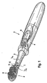
- eine perspektivische Gesamtansicht einer elektrischen Zahnbürste mit einer Leitung zur Förderung von Zahnpasta zum Zahnbürstenkopf,
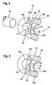
- Fig. 2:
- eine perspektivische Schnittansicht eines Steuerventils im geschlossenen Zustand, und
- Fig. 3:
- eine perspektivische Schnittansicht des Steuerventils aus
Fig. 2 im geöffneten Zustand. - Die in
Figur 1 gezeigte Zahnbürste umfasst ein Handteil 1 sowie einen Zahnbürstenkopf 2, der auf einem Bürstenrohr 3 sitzt, das ein stirnseitiges Ende des Handteils 1 bildet bzw. damit verbunden ist. Das Handteil 1 wird von einem Zahnbürstengehäuse 4 gebildet, in dem Batterien bzw. Akkus sowie ein Antriebsmotor angeordnet sind, der mittels eines Schalters 6 auf der Mantelfläche des Gehäuses 4 ein- und ausgeschaltet werden kann. Weiterhin ist im Handteil 1 ein Zahnpasta-Reservoir untergebracht, aus dem über eine im Bürstenrohr 3 untergebrachte Leitung 7a Zahnpasta zum Bürstenkopf 2 hin gefördert werden kann, wobei eine manuelle, aber auch eine motorische Förderung, z. B. mittels einer vom Antriebsmotor 5 angetriebenen Pumpe, vorgesehen sein kann. - Der Zahnbürstenkopf 2 besitzt ein antreibbares Borstenfeld 9, das über einen im Inneren des Bürstenrohres 3 aufgenommenen, nicht näher dargestellten Antriebsstrang rotatorisch oszillierend vom Antriebsmotor her angetrieben werden kann.
- Wie
Figur 1 zeigt, kann der Zahnbürstenkopf 2 an einer Schnittstelle 8 vom Handteil 1 getrennt werden. Die lösbare Verbindung zwischen dem Zahnbürstenkopf 2 und dem Handteil 1 wird durch eine Kupplungseinrichtung 10 bewirkt. Die Schnittstelle 8 kann auch zwischen dem Bürstenrohr 3 und dem Zahnbürstengehäuse 4 angeordnet sein, d.h. das Bürstenrohr 3 und der Zahnbürstenkopf 2 können einstückig ausgebildet sein. - Die Leitung 7 zur Förderung der Zahnpasta ist über die Schnittstelle 8 hinweggeführt, wobei in die Leitung 7 eine Fluid- bzw. Leitungskupplung 11 geschaltet ist, die Teil der Kupplungseinrichtung 10 ist und beim Aufstecken des Zahnbürstenkopfes 2 aufs Handteil 1 den handteilseitigen Abschnitt 7a der Leitung 7 mit dem bürstenkopfseitigen Abschnitt 7b der Leitung 7 kuppelt und andererseits beim Abnehmen des Zahnbürstenkopfes 2 ein Trennen der beiden Leitungsabschnitte 7a und 7b erlaubt.
- Die Leitungskupplung 11 umfasst dabei das in den
Figuren 2 und 3 gezeigte Steuerventil 12, das in der gezeichneten Ausführung mit dem bürstenkopfseitigen Abschnitt 7b der Leitung 7 fest verbunden ist und mit dem handteilseitigen Abschnitt 7a der Leitung 7 lösbar verbindbar ist. Es versteht sich jedoch, dass auch auf dem handteilseitigen Abschnitt 7a der Leitung 7 ein solches Steuerventil 12 sitzen kann. - Das Steuerventil 12 besteht aus einem einstückigen, vollelastischen Ventilkorpus 13, der in der gezeichneten Ausführung im wesentlichen rotationssymmetrisch um eine Ventillängsachse 14 ausgebildet ist. Wie die
Figuren 2 und 3 zeigen, ist in dem Ventilkorpus 13 ein Ventilkanal 15 ausgebildet, der von einem ebenfalls elastischen Steuerkörper 17 verschlossen und geöffnet werden kann. Als Steuerkörper 17 dient dabei eine Membran bzw. eine elastische Querwand 18, die im wesentlichen tellerförmig bzw. plattenförmig ausgebildet ist und sich im wesentlichen radial erstreckt. Die Quer- bzw. Sperrwand 18 ist dabei ringförmig umlaufend an der Innenwandung des Ventilkanals 15 angeformt und bildet sozusagen eine Trennwand, die den Ventilkanal 15 in die koaxial hintereinander liegenden Ventilkanalabschnitte 15a und 15b unterteilt. - In der Querwand 18 ist eine schlitzförmige Ventilkanalöffnung 19 ausgebildet, so dass die daran angrenzenden Abschnitte der Querwand 18 Dichtlippen 16 bilden, die im geschlossenen Zustand des Ventils gemäß
Figur 2 aneinander anliegen und die Ventilkanalöffnung 19 verschließen. - Wie
Figur 2 zeigt, besitzt der Ventilkorpus 13 im Bereich der Dichtlippen 16 auf seinem Außenumfang eine Einschnürung 20, in deren Bereich der Außendurchmesser des Ventilkorpus 13 verjüngt ist und die Wandstärke des Ventilkorpus 13 gegenüber den axial anschließenden Abschnitten reduziert ist. Dies erleichtert es, die Dichtlippen 16 zu öffnen. - Hierzu ist der gesamte Ventilkorpus 13 im Bereich des Kanalabschnittes 15a radial aufweitbar. Der Ventilkanalabschnitt 15a bildet einen Aufnahmestutzen, in den der handteilseitige Leitungsabschnitt 7a einsteckbar ist. Dabei ist der etwa zylindrische Ventilkorpusabschnitt 13a, der den genannten Kanalabschnitt 15a umgibt, mit seinem Innendurchmesser, der den Ventilkanalabschnitt 15a definiert, ein Stück kleiner ausgebildet als der Außendurchmesser des Leitungsabschnitts 7a, der in den Kanalabschnitt 15a eingeschoben werden soll. Wird der Zahnbürstenkopf 2 mittels der Kupplungseinrichtung 10 aufs Handteil 1 gesetzt, wird der Leitungsabschnitt 7a in den zu kleinen Kanalabschnitt 15a eingeschoben, so dass sich der Ventilkorpusabschnitt 13a aufweitet, wie dies
Figur 3 zeigt. Durch das Aufweiten des Ventilkorpusabschnitt 13a wird auch die Trennwand 18 radial auseinander gezogen, wodurch die Dichtlippen 16 aufmachen und sich die Ventilkanalöffnung 19 zwischen den Dichtlippen 16 bildet, wie diesFigur 3 zeigt. - Der genannte Ventilkorpusabschnitt 13a bildet insofern einerseits den Ventilöffner, mit Hilfe dessen das Steuerventil 12, genauer gesagt dessen elastische Dichtlippen 16, geöffnet werden können. Gleichzeitig bildet der genannte Ventilkorpusabschnitt 13a einen Kupplungsabschnitt, mit Hilfe dessen das Steuerventil 12 lösbar mit dem anzukuppelnden Leitungsabschnitt 7a verbindbar ist.
- Wie die
Figuren 2 und 3 zeigen, erstreckt sich der genannte Ventilkorpusabschnitt 13a in der gezeichneten Ausführung von der Einschnürung 20 ausgehend zu dem einen Ende des Ventilkorpus 13 hin und ist im wesentlichen zylindrisch ausgebildet, wobei am stirnseitigen Ende des Ventilkorpusabschnitt 13a ein flanschförmiger, radialer Randsteg ausgebildet ist, der als Dichtung fungieren kann. - Der gegenüberliegende, auf der anderen Seite der Dichtlippen 16 liegende Kanalabschnitt 15b wird ebenfalls von einem im wesentlichen zylindrischen Ventilkorpusabschnitt 13b umschlossen, der ebenfalls an seinem stirnseitigen Ende einen radial nach außen gerichteten Dichtungswulst 22 besitzt. Der Ventilkorpusabschnitt 13b dient dabei der Verbindung des Steuerventils 12 mit dem bürstenkopfseitigen Leitungsabschnitt 7b, an dem das Steuerventil 12 befestigt sein kann.
- Durch die frei wählbare Geometrie des Ventilkorpus 13, insbesondere seine Ventilkorpusabschnitte 13a und 13b, kann eine optimale Dichtfunktion gegenüber dem Bürstenrohr 3 bzw. dem Bürstenkopf 2 erreicht werden. Die eigentliche Schaltfunktion des Ventils liegt im Bereich der Dichtlippen 16 und des Durchmessers des Aufnahmestutzens 15a. Wird der Zahnbürstenkopf 2 ans Handteil 1 angekuppelt, wird der handteilseitige Leitungsabschnitt 7a in den genannten Aufnahmestutzen 15a eingeschoben, wodurch sich die Dichtlippen 16 öffnen und der Applikationsstoff, insbesondere die Zahnpasta, ungehindert hindurchfließen kann. Umgekehrt wird bei Abkupplung des Zahnbürstenkopfes 2 von dem Handteil 1 der genannte Leitungsabschnitt 7a wiederum aus dem Aufnahmestutzen 15a herausgezogen, wodurch sich die Dichtlippen 16 schließen und ein Eintrocknen der Zahnpasta verhindert wird.
Claims (25)
- Zahnbürstenkopf, der von einem Handteil einer Zahnbürste abnehmbar ist, mit einem Borstenfeld (9) und einer Kupplungseinrichtung (10) zum Ankuppeln ans Handteil (1) der Zahnbürste, wobei am Zahnbürstenkopf (2) ein bürstenkopfseitiger Leitungsabschnitt (7b) zum Fördern eines pastösen, gelartigen und/oder flüssigen Applikationsstoffs, insbesondere Zahnpasta, vorgesehen ist, und die Kupplungseinrichtung (10) eine Leitungskupplung (11) zum Ankuppeln des bürstenkopfseitigen Leitungsabschnitts (7b) an einen handteilseitigen Leitungsabschnitt (7a) aufweist, dadurch gekennzeichnet, dass die Leitungskupplung (11) ein Steuerventil (12) aufweist, das beim Ankuppeln des Bürstenkopfs (2) ans Handteil (1) der Zahnbürste durch Eingriff eines am Handteil (1) vorgesehenen Ventilbetätigers, insbesondere das Ende des handteilseitigen Leitungsabschnitts, öffnet und den handteilseitigen Leitungsabschnitt (7a) mit dem bürstenkopfseitigen Leitungsabschnitt (7b) verbindet, sowie beim Abkuppeln vom Handteil (1) den bürstenkopfseitigen Leitungsabschnitt (7b) verschließt.
- Zahnbürstenkopf nach dem vorhergehenden Anspruch, wobei das Steuerventil (12) einen Ventilkorpus (13) mit einem durch diesen hindurch tretenden Ventilkanal (15) aufweist, in dem eine elastische Sperrwand (18) mit einer sich elastisch schließenden Ventilkanalöffnung (19) vorgesehen ist.
- Zahnbürstenkopf nach einem der vorhergehenden Ansprüche, wobei das Steuerventil (12) einen elastischen Ventilöffner (13a) aufweist, der von einem Ende des handteilseitigen Leitungsabschnitts (7a) elastisch verform- und betätigbar ist.
- Zahnbürstenkopf nach dem vorhergehenden Anspruch, wobei der Ventilöffner (13a) einen Kupplungsabschnitt zum Ankuppeln des handteilseitigen Leitungsabschnitts (7a) bildet.
- Zahnbürstenkopf nach einem der beiden vorhergehenden Ansprüche, wobei der Ventilöffner (13a) einen Aufnahmestutzen bildet, der durch Einfahren des handteilseitigen Leitungsabschnitts (7a) elastisch radial aufweitbar ist.
- Zahnbürstenkopf nach einem der vorhergehenden Ansprüche, wobei das Steuerventil (12) zumindest eine elastische Dichtlippe (16) aufweist, die von dem handteilseitigen Ventilbetätiger betätigbar ist.
- Zahnbürstenkopf nach den beiden vorhergehenden Ansprüchen, wobei die zumindest eine Dichtlippe (16) einen Boden des Aufnahmestutzens (15a) bildet.
- Zahnbürstenkopf nach einem der vorhergehenden Ansprüche, wobei die zumindest eine Dichtlippe (16) mit dem Ventilöffner (13a) verbunden ist derart, dass die Dichtlippe (16) durch radiales Aufweiten des Ventilöffners (13a) öffnet.
- Zahnbürstenkopf nach einem der vorhergehenden Ansprüche in Verbindung mit Anspruch 2, wobei die zumindest eine Dichtlippe von der elastischen Sperrwand (18) gebildet ist, wobei vorzugsweise die genannte Sperrwand (18) eine etwa mittig angeordnete und/oder schlitzförmige Ventilkanalöffnung (19) aufweist.
- Zahnbürstenkopf nach einem der vorhergehenden Ansprüche, wobei das Steuerventil (12) auf seinem Außenumfang im Bereich der zumindest einen Dichtlippe (16) eine Einschnürung (20) aufweist.
- Zahnbürstenkopf nach einem der vorhergehenden Ansprüche, wobei das Steuerventil (12) einstückig ausgebildet ist und/oder aus einem elastischen Vollkorpus, vorzugsweise aus Weichkunststoff und/oder Gummi, besteht.
- Zahnbürstenkopf nach einem der vorhergehenden Ansprüche, wobei das Steuerventil (12) einen Verbindungsabschnitt (15b) besitzt, der auf und/oder in den bürstenkopfseitigen Leitungsabschnitt (7b) steckbar ist.
- Handteil einer Zahnbürste mit einer Kupplungseinrichtung (10) zum Ankuppeln eines ein Borstenfeld (9) tragenden Zahnbürstenkopfs (2), mit einem handteilseitigem Leitungsabschnitt (7a) zum Fördern eines pastösen, gelartigen und/oder flüssigen Applikationsstoffs, insbesondere Zahnpasta, zu dem Zahnbürstenkopf (2), wobei die Kupplungseinrichtung (10) eine Leitungskupplung (11) zum Ankuppeln des handteilseitigem Leitungsabschnitts (7a) an einen bürstenkopfseitigen Leitungsabschnitt (7b) zur Förderung des Applikationsstoffs aufweist, dadurch gekennzeichnet, dass die Leitungskupplung (11) ein Steuerventil (12) aufweist, das beim Ankuppeln des Bürstenkopfs (2) ans Handteil (1) der Zahnbürste durch Eingriff eines am Zahnbürstenkopf (2) vorgesehenen Ventilbetätigers, insbesondere das Ende des bürstenkopfseitigen Leitungsabschnitts, öffnet und den handteilseitigen Leitungsabschnitt (7a) mit dem bürstenkopfseitigen Leitungsabschnitt (7b) verbindet, sowie beim Abkuppeln vom Handteil (1) den handteilseitigen Leitungsabschnitt (7a) verschließt.
- Handteil nach dem vorhergehenden Anspruch, wobei das Steuerventil (12) einen Ventilkorpus (13) mit einem durch diesen hindurch tretenden Ventilkanal (15) aufweist, in dem eine elastische Sperrwand (18) mit einer sich elastisch schließenden Ventilkanalöffnung (19) vorgesehen ist.
- Handteil nach einem der Ansprüche 13 oder 14, wobei das Steuerventil (12) einen elastischen Ventilöffner (15a) aufweist, der von einem Ende des bürstenkopfseitigen Leitungsabschnitts (7b) elastisch verform- und betätigbar ist.
- Handteil nach dem vorhergehenden Anspruch, wobei der Ventilöffner (15a) einen Kupplungsabschnitt zum Ankuppeln des bürstenkopfseitigen Leitungsabschnitts (7b) bildet.
- Handteil nach einem der beiden vorhergehenden Ansprüche, wobei der Ventilöffner (15a) einen Aufnahmestutzen bildet, der durch Einfahren des bürstenkopfseitigen Leitungsendes (7b) elastisch radial aufweitbar ist.
- Handteil nach einem der Ansprüche 13 bis 17, wobei das Steuerventil (12) zumindest eine elastische Dichtlippe (16) aufweist, die von dem bürstenkopfseitigen Ventilbetätiger betätigbar ist.
- Handteil nach den beiden vorhergehenden Ansprüchen, wobei die zumindest eine Dichtlippe (16) einen Boden des Aufnahmestutzens (15a) bildet.
- Handteil nach einem der Ansprüche 13 bis 19, wobei die zumindest eine Dichtlippe (16) mit dem Ventilöffner (15a) verbunden ist derart, dass die Dichtlippe (16) durch radiales Aufweiten des Ventilöffners (13a, 15a) öffnet.
- Handteil nach einem der Ansprüche 13 bis 20 in Verbindung mit Anspruch 14, wobei die zumindest eine Dichtlippe von der elastischen Sperrwand (18) gebildet ist, wobei vorzugsweise die genannte Sperrwand (18) eine etwa mittig angeordnete und/oder schlitzförmige Ventilkanalöffnung (19) aufweist.
- Handteil nach einem der Ansprüche 13 bis 21, wobei das Steuerventil (12) auf seinem Außenumfang im Bereich der zumindest einen Dichtlippe (16) eine Querschnittseinschnürung (20) aufweist.
- Handteil nach einem der Ansprüche 13 bis 22, wobei das Steuerventil (12) einstückig ausgebildet ist und/oder aus einem elastischen Vollkorpus, vorzugsweise aus Weichkunststoff und/oder Gummi, besteht.
- Handteil nach einem der Ansprüche 13 bis 23, wobei das Steuerventil (12) einen Verbindungsabschnitt (15b) besitzt, der auf und/oder in den handteilseitigen Leitungsabschnitt (7a) steckbar ist.
- Elektrische Zahnbürste mit einem Handteil nach einem der Ansprüche 13 bis 24 sowie einem damit kuppelbaren Zahnbürstenkopf (2) nach einem der Ansprüche 1 bis 12.
Applications Claiming Priority (2)
| Application Number | Priority Date | Filing Date | Title |
|---|---|---|---|
| DE102005061491A DE102005061491A1 (de) | 2005-12-22 | 2005-12-22 | Zahnbürste |
| PCT/EP2006/011967 WO2007079884A1 (de) | 2005-12-22 | 2006-12-13 | Zahnbürste |
Publications (2)
| Publication Number | Publication Date |
|---|---|
| EP1962637A1 EP1962637A1 (de) | 2008-09-03 |
| EP1962637B1 true EP1962637B1 (de) | 2012-10-31 |
Family
ID=37845299
Family Applications (1)
| Application Number | Title | Priority Date | Filing Date |
|---|---|---|---|
| EP06829544A Not-in-force EP1962637B1 (de) | 2005-12-22 | 2006-12-13 | Zahnbürste |
Country Status (7)
| Country | Link |
|---|---|
| US (1) | US20090000048A1 (de) |
| EP (1) | EP1962637B1 (de) |
| JP (1) | JP2009520534A (de) |
| CN (1) | CN101346076B (de) |
| CA (1) | CA2634853A1 (de) |
| DE (1) | DE102005061491A1 (de) |
| WO (1) | WO2007079884A1 (de) |
Families Citing this family (2)
| Publication number | Priority date | Publication date | Assignee | Title |
|---|---|---|---|---|
| DE102007062368A1 (de) * | 2007-06-29 | 2009-01-02 | Braun Gmbh | Ventilkopplung |
| US9930957B2 (en) * | 2015-03-09 | 2018-04-03 | Martin E. Hellkamp | Dental devices with liquid applicator |
Family Cites Families (27)
| Publication number | Priority date | Publication date | Assignee | Title |
|---|---|---|---|---|
| US3592551A (en) * | 1969-07-24 | 1971-07-13 | Carl O Muglia | Aerosol charged toothbrush |
| DE2514031A1 (de) * | 1975-03-29 | 1976-10-07 | Elmar Maeder | Zahnbuerste |
| US4615635A (en) * | 1985-06-10 | 1986-10-07 | Kim Kun H | Toothbrush with flow control valve |
| US4752287A (en) * | 1986-12-30 | 1988-06-21 | Bioresearch, Inc. | Syringe check valve |
| US5039244A (en) * | 1990-03-14 | 1991-08-13 | Shuchao Cheng | Toothbrush and toothpaste system |
| US5301381A (en) * | 1992-12-07 | 1994-04-12 | Klupt Michael F | Toothbrush system |
| GB9319686D0 (en) * | 1993-09-23 | 1993-11-10 | Taghavi Said | Toothbrush with toothpaste reservoir and bristle adapters |
| US5909977A (en) * | 1997-03-31 | 1999-06-08 | Kuo; Youti | Dentifrice dispensing toothbrush with refillable cartridge |
| US6039301A (en) * | 1997-04-22 | 2000-03-21 | U.S. Philips Corporation | Container and sealing device for use in the container |
| DE19729516C2 (de) * | 1997-07-10 | 1999-04-22 | Georg Wiegner | Pumpe zum dosierten Austragen von flüssigen, gelartigen oder viskosen Substanzen |
| US6095710A (en) * | 1998-07-16 | 2000-08-01 | Ayeni; Joseph | Toothpaste dispensing toothbrush with valve |
| US6402410B1 (en) * | 1999-01-13 | 2002-06-11 | Philips Oral Healthcare | Fluid-dispensing and refilling system for a power toothbrush |
| US6220772B1 (en) * | 1999-01-13 | 2001-04-24 | Optiva Corporation | Fluid-dispensing and refilling system for a power toothbrush |
| US6241412B1 (en) * | 1999-05-19 | 2001-06-05 | Norbert Spies | Cartridge toothbrush |
| ES2376730T3 (es) * | 2000-07-24 | 2012-03-16 | Obrist Closures Switzerland Gmbh | Anillo activador para una membrana de cierre |
| US6434773B1 (en) * | 2000-08-28 | 2002-08-20 | Youti Kuo | Dentifrice dispensing electrical toothbrush with snap-on dual brush unit |
| US6371674B1 (en) * | 2000-11-06 | 2002-04-16 | Sharon Lerner | Plaque disclosing agent dispensing toothbrush |
| US6648641B1 (en) * | 2000-11-22 | 2003-11-18 | The Procter & Gamble Company | Apparatus, method and product for treating teeth |
| ATE397422T1 (de) * | 2001-02-12 | 2008-06-15 | Koninkl Philips Electronics Nv | Schallantriebs-zahnbürste mit mehreren behältern |
| US6766824B2 (en) * | 2001-12-20 | 2004-07-27 | Koninklijke Philips Electronics N.V. | Fluid control valve and a feedback control system therefor |
| US20030150472A1 (en) * | 2002-02-14 | 2003-08-14 | Johnson Elizabeth M. | Toothpaste dispensing toothbrush device |
| WO2003103985A1 (en) * | 2002-04-22 | 2003-12-18 | Gordon David C | Toothbrush assembly with toothpaste dispenser |
| US7244073B2 (en) * | 2003-05-27 | 2007-07-17 | Trocino Richard B | Travel toothbrush assembly |
| CN2712150Y (zh) * | 2004-04-01 | 2005-07-27 | 付宝宝 | 自带牙膏的组合牙刷 |
| US20050271531A1 (en) * | 2004-06-03 | 2005-12-08 | Brown William R Jr | Oral care device |
| US6902337B1 (en) * | 2004-06-23 | 2005-06-07 | Youti Kuo | Dentifrice dispensing electrical toothbrush |
| US20070017582A1 (en) * | 2005-07-20 | 2007-01-25 | Chenvainu Alexander T | Fluid couplings |
-
2005
- 2005-12-22 DE DE102005061491A patent/DE102005061491A1/de not_active Withdrawn
-
2006
- 2006-12-13 JP JP2008546198A patent/JP2009520534A/ja active Pending
- 2006-12-13 EP EP06829544A patent/EP1962637B1/de not_active Not-in-force
- 2006-12-13 US US12/158,758 patent/US20090000048A1/en not_active Abandoned
- 2006-12-13 WO PCT/EP2006/011967 patent/WO2007079884A1/de active Application Filing
- 2006-12-13 CA CA002634853A patent/CA2634853A1/en not_active Abandoned
- 2006-12-13 CN CN2006800488822A patent/CN101346076B/zh not_active Expired - Fee Related
Also Published As
| Publication number | Publication date |
|---|---|
| EP1962637A1 (de) | 2008-09-03 |
| JP2009520534A (ja) | 2009-05-28 |
| CN101346076A (zh) | 2009-01-14 |
| US20090000048A1 (en) | 2009-01-01 |
| CA2634853A1 (en) | 2007-07-19 |
| WO2007079884A1 (de) | 2007-07-19 |
| DE102005061491A1 (de) | 2007-07-05 |
| CN101346076B (zh) | 2010-06-30 |
Similar Documents
| Publication | Publication Date | Title |
|---|---|---|
| EP0023672B1 (de) | Zahnärztliches Handstück mit einem Ventil zur Steuerung des Durchflusses eines strömenden Mediums | |
| DE60019459T2 (de) | Schlauchverbinder | |
| EP1215167B1 (de) | Spenderausguss für fliessfähige Medien | |
| EP2021677B1 (de) | Molch mit verbesserter dichtwirkung | |
| DE102005006841B4 (de) | Fluidfilter mit kostengünstigem Gehäuse | |
| EP1015340A1 (de) | Spenderpumpe, spender und spender-baukastensystem | |
| CH648758A5 (de) | Verriegelbare kupplung, ihre kupplungshaelften und vorrichtung fuer die kontinuierliche ambulante peritonealdialyse mit dieser kupplung. | |
| EP2524711B1 (de) | Verbindungssystem zur Herstellung eines Verbindungskanals für Körperflüssigkeiten | |
| DE2207288A1 (de) | Pinsel und verfahren zu dessen herstellung | |
| DE8410069U1 (de) | Anschlussvorrichtung | |
| DE7811524U1 (de) | Anordnung zur drehbaren verbindung eines saugschlauches mit einem kupplungsstueck bei einem staubsauger | |
| EP1637065B1 (de) | Endoskopisches Instrument | |
| EP1962637B1 (de) | Zahnbürste | |
| EP0064949A1 (de) | Behälterverschluss für aufsetzbare Abzapfvorrichtungen | |
| DE2618158C3 (de) | Zahnärztliche Turbinenhandstückanordnung | |
| DE2653588C2 (de) | Zahnärztliches Handstück | |
| DE102008040082A1 (de) | Farbauftragvorrichtung sowie Verfahren zum Reinigen einer Farbauftragvorrichtung | |
| DE3204726A1 (de) | Steckerteil einer schnellkupplung fuer rohr- oder schlauchleitungen | |
| EP3589556B1 (de) | Behälterverpackung und verfahren zur deren herstellung | |
| EP0935071A1 (de) | Elastomerstator für Exzenterschneckenpumpen | |
| EP1127661A1 (de) | Befestigungsvorrichtung zur Anbringung eines Stiels an einem Werkzeug | |
| DE19507640C1 (de) | Aufsteckbarer Wasserhahnadapter | |
| DE1902655A1 (de) | Hydraulisches Antriebssystem | |
| DE102004063400B4 (de) | Verfahren und Vorrichtung zum Applizieren von elastischen Schläuchen auf Endoskope | |
| DE2806588A1 (de) | Befestigung eines schlauches an einem anschlusstueck |
Legal Events
| Date | Code | Title | Description |
|---|---|---|---|
| PUAI | Public reference made under article 153(3) epc to a published international application that has entered the european phase |
Free format text: ORIGINAL CODE: 0009012 |
|
| 17P | Request for examination filed |
Effective date: 20080605 |
|
| AK | Designated contracting states |
Kind code of ref document: A1 Designated state(s): AT BE BG CH CY CZ DE DK EE ES FI FR GB GR HU IE IS IT LI LT LU LV MC NL PL PT RO SE SI SK TR |
|
| RIN1 | Information on inventor provided before grant (corrected) |
Inventor name: LANDFESTER, ALEXANDER Inventor name: KLAWUHN, MANFRED |
|
| 17Q | First examination report despatched |
Effective date: 20110503 |
|
| GRAP | Despatch of communication of intention to grant a patent |
Free format text: ORIGINAL CODE: EPIDOSNIGR1 |
|
| DAX | Request for extension of the european patent (deleted) | ||
| GRAS | Grant fee paid |
Free format text: ORIGINAL CODE: EPIDOSNIGR3 |
|
| GRAA | (expected) grant |
Free format text: ORIGINAL CODE: 0009210 |
|
| AK | Designated contracting states |
Kind code of ref document: B1 Designated state(s): AT BE BG CH CY CZ DE DK EE ES FI FR GB GR HU IE IS IT LI LT LU LV MC NL PL PT RO SE SI SK TR |
|
| REG | Reference to a national code |
Ref country code: GB Ref legal event code: FG4D Free format text: NOT ENGLISH Ref country code: CH Ref legal event code: EP |
|
| REG | Reference to a national code |
Ref country code: CH Ref legal event code: NV Representative=s name: BOHEST AG, CH Ref country code: AT Ref legal event code: REF Ref document number: 581521 Country of ref document: AT Kind code of ref document: T Effective date: 20121115 |
|
| REG | Reference to a national code |
Ref country code: IE Ref legal event code: FG4D Free format text: LANGUAGE OF EP DOCUMENT: GERMAN |
|
| REG | Reference to a national code |
Ref country code: DE Ref legal event code: R096 Ref document number: 502006012174 Country of ref document: DE Effective date: 20121227 |
|
| REG | Reference to a national code |
Ref country code: NL Ref legal event code: T3 |
|
| REG | Reference to a national code |
Ref country code: LT Ref legal event code: MG4D |
|
| PG25 | Lapsed in a contracting state [announced via postgrant information from national office to epo] |
Ref country code: SE Free format text: LAPSE BECAUSE OF FAILURE TO SUBMIT A TRANSLATION OF THE DESCRIPTION OR TO PAY THE FEE WITHIN THE PRESCRIBED TIME-LIMIT Effective date: 20121031 Ref country code: FI Free format text: LAPSE BECAUSE OF FAILURE TO SUBMIT A TRANSLATION OF THE DESCRIPTION OR TO PAY THE FEE WITHIN THE PRESCRIBED TIME-LIMIT Effective date: 20121031 Ref country code: IS Free format text: LAPSE BECAUSE OF FAILURE TO SUBMIT A TRANSLATION OF THE DESCRIPTION OR TO PAY THE FEE WITHIN THE PRESCRIBED TIME-LIMIT Effective date: 20130228 Ref country code: LT Free format text: LAPSE BECAUSE OF FAILURE TO SUBMIT A TRANSLATION OF THE DESCRIPTION OR TO PAY THE FEE WITHIN THE PRESCRIBED TIME-LIMIT Effective date: 20121031 Ref country code: ES Free format text: LAPSE BECAUSE OF FAILURE TO SUBMIT A TRANSLATION OF THE DESCRIPTION OR TO PAY THE FEE WITHIN THE PRESCRIBED TIME-LIMIT Effective date: 20130211 |
|
| PG25 | Lapsed in a contracting state [announced via postgrant information from national office to epo] |
Ref country code: CY Free format text: LAPSE BECAUSE OF FAILURE TO SUBMIT A TRANSLATION OF THE DESCRIPTION OR TO PAY THE FEE WITHIN THE PRESCRIBED TIME-LIMIT Effective date: 20121031 Ref country code: SI Free format text: LAPSE BECAUSE OF FAILURE TO SUBMIT A TRANSLATION OF THE DESCRIPTION OR TO PAY THE FEE WITHIN THE PRESCRIBED TIME-LIMIT Effective date: 20121031 Ref country code: LV Free format text: LAPSE BECAUSE OF FAILURE TO SUBMIT A TRANSLATION OF THE DESCRIPTION OR TO PAY THE FEE WITHIN THE PRESCRIBED TIME-LIMIT Effective date: 20121031 Ref country code: GR Free format text: LAPSE BECAUSE OF FAILURE TO SUBMIT A TRANSLATION OF THE DESCRIPTION OR TO PAY THE FEE WITHIN THE PRESCRIBED TIME-LIMIT Effective date: 20130201 Ref country code: PL Free format text: LAPSE BECAUSE OF FAILURE TO SUBMIT A TRANSLATION OF THE DESCRIPTION OR TO PAY THE FEE WITHIN THE PRESCRIBED TIME-LIMIT Effective date: 20121031 Ref country code: PT Free format text: LAPSE BECAUSE OF FAILURE TO SUBMIT A TRANSLATION OF THE DESCRIPTION OR TO PAY THE FEE WITHIN THE PRESCRIBED TIME-LIMIT Effective date: 20130228 |
|
| BERE | Be: lapsed |
Owner name: BRAUN G.M.B.H. Effective date: 20121231 |
|
| PG25 | Lapsed in a contracting state [announced via postgrant information from national office to epo] |
Ref country code: MC Free format text: LAPSE BECAUSE OF NON-PAYMENT OF DUE FEES Effective date: 20121231 Ref country code: BG Free format text: LAPSE BECAUSE OF FAILURE TO SUBMIT A TRANSLATION OF THE DESCRIPTION OR TO PAY THE FEE WITHIN THE PRESCRIBED TIME-LIMIT Effective date: 20130131 Ref country code: DK Free format text: LAPSE BECAUSE OF FAILURE TO SUBMIT A TRANSLATION OF THE DESCRIPTION OR TO PAY THE FEE WITHIN THE PRESCRIBED TIME-LIMIT Effective date: 20121031 Ref country code: EE Free format text: LAPSE BECAUSE OF FAILURE TO SUBMIT A TRANSLATION OF THE DESCRIPTION OR TO PAY THE FEE WITHIN THE PRESCRIBED TIME-LIMIT Effective date: 20121031 Ref country code: CZ Free format text: LAPSE BECAUSE OF FAILURE TO SUBMIT A TRANSLATION OF THE DESCRIPTION OR TO PAY THE FEE WITHIN THE PRESCRIBED TIME-LIMIT Effective date: 20121031 Ref country code: SK Free format text: LAPSE BECAUSE OF FAILURE TO SUBMIT A TRANSLATION OF THE DESCRIPTION OR TO PAY THE FEE WITHIN THE PRESCRIBED TIME-LIMIT Effective date: 20121031 |
|
| PG25 | Lapsed in a contracting state [announced via postgrant information from national office to epo] |
Ref country code: IT Free format text: LAPSE BECAUSE OF FAILURE TO SUBMIT A TRANSLATION OF THE DESCRIPTION OR TO PAY THE FEE WITHIN THE PRESCRIBED TIME-LIMIT Effective date: 20121031 Ref country code: RO Free format text: LAPSE BECAUSE OF FAILURE TO SUBMIT A TRANSLATION OF THE DESCRIPTION OR TO PAY THE FEE WITHIN THE PRESCRIBED TIME-LIMIT Effective date: 20121031 |
|
| PLBE | No opposition filed within time limit |
Free format text: ORIGINAL CODE: 0009261 |
|
| STAA | Information on the status of an ep patent application or granted ep patent |
Free format text: STATUS: NO OPPOSITION FILED WITHIN TIME LIMIT |
|
| REG | Reference to a national code |
Ref country code: IE Ref legal event code: MM4A |
|
| PG25 | Lapsed in a contracting state [announced via postgrant information from national office to epo] |
Ref country code: BE Free format text: LAPSE BECAUSE OF NON-PAYMENT OF DUE FEES Effective date: 20121231 |
|
| 26N | No opposition filed |
Effective date: 20130801 |
|
| PG25 | Lapsed in a contracting state [announced via postgrant information from national office to epo] |
Ref country code: IE Free format text: LAPSE BECAUSE OF NON-PAYMENT OF DUE FEES Effective date: 20121213 |
|
| REG | Reference to a national code |
Ref country code: DE Ref legal event code: R097 Ref document number: 502006012174 Country of ref document: DE Effective date: 20130801 |
|
| REG | Reference to a national code |
Ref country code: AT Ref legal event code: MM01 Ref document number: 581521 Country of ref document: AT Kind code of ref document: T Effective date: 20121213 |
|
| PG25 | Lapsed in a contracting state [announced via postgrant information from national office to epo] |
Ref country code: TR Free format text: LAPSE BECAUSE OF FAILURE TO SUBMIT A TRANSLATION OF THE DESCRIPTION OR TO PAY THE FEE WITHIN THE PRESCRIBED TIME-LIMIT Effective date: 20121031 |
|
| PG25 | Lapsed in a contracting state [announced via postgrant information from national office to epo] |
Ref country code: LU Free format text: LAPSE BECAUSE OF NON-PAYMENT OF DUE FEES Effective date: 20121213 Ref country code: AT Free format text: LAPSE BECAUSE OF NON-PAYMENT OF DUE FEES Effective date: 20121213 |
|
| PG25 | Lapsed in a contracting state [announced via postgrant information from national office to epo] |
Ref country code: HU Free format text: LAPSE BECAUSE OF FAILURE TO SUBMIT A TRANSLATION OF THE DESCRIPTION OR TO PAY THE FEE WITHIN THE PRESCRIBED TIME-LIMIT Effective date: 20061213 |
|
| REG | Reference to a national code |
Ref country code: FR Ref legal event code: PLFP Year of fee payment: 10 |
|
| PGFP | Annual fee paid to national office [announced via postgrant information from national office to epo] |
Ref country code: GB Payment date: 20151125 Year of fee payment: 10 Ref country code: CH Payment date: 20151125 Year of fee payment: 10 |
|
| PGFP | Annual fee paid to national office [announced via postgrant information from national office to epo] |
Ref country code: FR Payment date: 20151124 Year of fee payment: 10 Ref country code: NL Payment date: 20151207 Year of fee payment: 10 |
|
| PGFP | Annual fee paid to national office [announced via postgrant information from national office to epo] |
Ref country code: DE Payment date: 20151230 Year of fee payment: 10 |
|
| REG | Reference to a national code |
Ref country code: DE Ref legal event code: R119 Ref document number: 502006012174 Country of ref document: DE |
|
| REG | Reference to a national code |
Ref country code: CH Ref legal event code: PL |
|
| REG | Reference to a national code |
Ref country code: NL Ref legal event code: MM Effective date: 20170101 |
|
| GBPC | Gb: european patent ceased through non-payment of renewal fee |
Effective date: 20161213 |
|
| PG25 | Lapsed in a contracting state [announced via postgrant information from national office to epo] |
Ref country code: NL Free format text: LAPSE BECAUSE OF NON-PAYMENT OF DUE FEES Effective date: 20170101 |
|
| REG | Reference to a national code |
Ref country code: FR Ref legal event code: ST Effective date: 20170831 |
|
| PG25 | Lapsed in a contracting state [announced via postgrant information from national office to epo] |
Ref country code: CH Free format text: LAPSE BECAUSE OF NON-PAYMENT OF DUE FEES Effective date: 20161231 Ref country code: FR Free format text: LAPSE BECAUSE OF NON-PAYMENT OF DUE FEES Effective date: 20170102 Ref country code: LI Free format text: LAPSE BECAUSE OF NON-PAYMENT OF DUE FEES Effective date: 20161231 |
|
| PG25 | Lapsed in a contracting state [announced via postgrant information from national office to epo] |
Ref country code: DE Free format text: LAPSE BECAUSE OF NON-PAYMENT OF DUE FEES Effective date: 20170701 Ref country code: GB Free format text: LAPSE BECAUSE OF NON-PAYMENT OF DUE FEES Effective date: 20161213 |