EP2221902A1 - Battery operated appliances - Google Patents
Battery operated appliances Download PDFInfo
- Publication number
- EP2221902A1 EP2221902A1 EP10162831A EP10162831A EP2221902A1 EP 2221902 A1 EP2221902 A1 EP 2221902A1 EP 10162831 A EP10162831 A EP 10162831A EP 10162831 A EP10162831 A EP 10162831A EP 2221902 A1 EP2221902 A1 EP 2221902A1
- Authority
- EP
- European Patent Office
- Prior art keywords
- electrically conductive
- appliance
- housing
- conductive member
- battery cover
- Prior art date
- Legal status (The legal status is an assumption and is not a legal conclusion. Google has not performed a legal analysis and makes no representation as to the accuracy of the status listed.)
- Withdrawn
Links
Images
Classifications
-
- H—ELECTRICITY
- H01—ELECTRIC ELEMENTS
- H01M—PROCESSES OR MEANS, e.g. BATTERIES, FOR THE DIRECT CONVERSION OF CHEMICAL ENERGY INTO ELECTRICAL ENERGY
- H01M50/00—Constructional details or processes of manufacture of the non-active parts of electrochemical cells other than fuel cells, e.g. hybrid cells
- H01M50/20—Mountings; Secondary casings or frames; Racks, modules or packs; Suspension devices; Shock absorbers; Transport or carrying devices; Holders
-
- A—HUMAN NECESSITIES
- A61—MEDICAL OR VETERINARY SCIENCE; HYGIENE
- A61C—DENTISTRY; APPARATUS OR METHODS FOR ORAL OR DENTAL HYGIENE
- A61C17/00—Devices for cleaning, polishing, rinsing or drying teeth, teeth cavities or prostheses; Saliva removers; Dental appliances for receiving spittle
- A61C17/16—Power-driven cleaning or polishing devices
- A61C17/22—Power-driven cleaning or polishing devices with brushes, cushions, cups, or the like
- A61C17/225—Handles or details thereof
-
- B—PERFORMING OPERATIONS; TRANSPORTING
- B26—HAND CUTTING TOOLS; CUTTING; SEVERING
- B26B—HAND-HELD CUTTING TOOLS NOT OTHERWISE PROVIDED FOR
- B26B19/00—Clippers or shavers operating with a plurality of cutting edges, e.g. hair clippers, dry shavers
- B26B19/38—Details of, or accessories for, hair clippers, or dry shavers, e.g. housings, casings, grips, guards
- B26B19/3853—Housing or handle
-
- B—PERFORMING OPERATIONS; TRANSPORTING
- B26—HAND CUTTING TOOLS; CUTTING; SEVERING
- B26B—HAND-HELD CUTTING TOOLS NOT OTHERWISE PROVIDED FOR
- B26B19/00—Clippers or shavers operating with a plurality of cutting edges, e.g. hair clippers, dry shavers
- B26B19/38—Details of, or accessories for, hair clippers, or dry shavers, e.g. housings, casings, grips, guards
- B26B19/3873—Electric features; Charging; Computing devices
-
- B—PERFORMING OPERATIONS; TRANSPORTING
- B26—HAND CUTTING TOOLS; CUTTING; SEVERING
- B26B—HAND-HELD CUTTING TOOLS NOT OTHERWISE PROVIDED FOR
- B26B21/00—Razors of the open or knife type; Safety razors or other shaving implements of the planing type; Hair-trimming devices involving a razor-blade; Equipment therefor
- B26B21/08—Razors of the open or knife type; Safety razors or other shaving implements of the planing type; Hair-trimming devices involving a razor-blade; Equipment therefor involving changeable blades
- B26B21/14—Safety razors with one or more blades arranged transversely to the handle
- B26B21/38—Safety razors with one or more blades arranged transversely to the handle with provision for reciprocating the blade by means other than rollers
-
- B—PERFORMING OPERATIONS; TRANSPORTING
- B26—HAND CUTTING TOOLS; CUTTING; SEVERING
- B26B—HAND-HELD CUTTING TOOLS NOT OTHERWISE PROVIDED FOR
- B26B21/00—Razors of the open or knife type; Safety razors or other shaving implements of the planing type; Hair-trimming devices involving a razor-blade; Equipment therefor
- B26B21/40—Details or accessories
- B26B21/52—Handles, e.g. tiltable, flexible
- B26B21/526—Electric features
-
- H—ELECTRICITY
- H01—ELECTRIC ELEMENTS
- H01M—PROCESSES OR MEANS, e.g. BATTERIES, FOR THE DIRECT CONVERSION OF CHEMICAL ENERGY INTO ELECTRICAL ENERGY
- H01M50/00—Constructional details or processes of manufacture of the non-active parts of electrochemical cells other than fuel cells, e.g. hybrid cells
- H01M50/20—Mountings; Secondary casings or frames; Racks, modules or packs; Suspension devices; Shock absorbers; Transport or carrying devices; Holders
- H01M50/204—Racks, modules or packs for multiple batteries or multiple cells
- H01M50/207—Racks, modules or packs for multiple batteries or multiple cells characterised by their shape
- H01M50/213—Racks, modules or packs for multiple batteries or multiple cells characterised by their shape adapted for cells having curved cross-section, e.g. round or elliptic
-
- H—ELECTRICITY
- H01—ELECTRIC ELEMENTS
- H01R—ELECTRICALLY-CONDUCTIVE CONNECTIONS; STRUCTURAL ASSOCIATIONS OF A PLURALITY OF MUTUALLY-INSULATED ELECTRICAL CONNECTING ELEMENTS; COUPLING DEVICES; CURRENT COLLECTORS
- H01R13/00—Details of coupling devices of the kinds covered by groups H01R12/70 or H01R24/00 - H01R33/00
- H01R13/02—Contact members
- H01R13/20—Pins, blades, or sockets shaped, or provided with separate member, to retain co-operating parts together
- H01R13/213—Pins, blades, or sockets shaped, or provided with separate member, to retain co-operating parts together by bayonet connection
-
- H—ELECTRICITY
- H01—ELECTRIC ELEMENTS
- H01R—ELECTRICALLY-CONDUCTIVE CONNECTIONS; STRUCTURAL ASSOCIATIONS OF A PLURALITY OF MUTUALLY-INSULATED ELECTRICAL CONNECTING ELEMENTS; COUPLING DEVICES; CURRENT COLLECTORS
- H01R13/00—Details of coupling devices of the kinds covered by groups H01R12/70 or H01R24/00 - H01R33/00
- H01R13/62—Means for facilitating engagement or disengagement of coupling parts or for holding them in engagement
- H01R13/625—Casing or ring with bayonet engagement
-
- H—ELECTRICITY
- H01—ELECTRIC ELEMENTS
- H01R—ELECTRICALLY-CONDUCTIVE CONNECTIONS; STRUCTURAL ASSOCIATIONS OF A PLURALITY OF MUTUALLY-INSULATED ELECTRICAL CONNECTING ELEMENTS; COUPLING DEVICES; CURRENT COLLECTORS
- H01R33/00—Coupling devices specially adapted for supporting apparatus and having one part acting as a holder providing support and electrical connection via a counterpart which is structurally associated with the apparatus, e.g. lamp holders; Separate parts thereof
- H01R33/05—Two-pole devices
- H01R33/46—Two-pole devices for bayonet type base
-
- Y—GENERAL TAGGING OF NEW TECHNOLOGICAL DEVELOPMENTS; GENERAL TAGGING OF CROSS-SECTIONAL TECHNOLOGIES SPANNING OVER SEVERAL SECTIONS OF THE IPC; TECHNICAL SUBJECTS COVERED BY FORMER USPC CROSS-REFERENCE ART COLLECTIONS [XRACs] AND DIGESTS
- Y02—TECHNOLOGIES OR APPLICATIONS FOR MITIGATION OR ADAPTATION AGAINST CLIMATE CHANGE
- Y02E—REDUCTION OF GREENHOUSE GAS [GHG] EMISSIONS, RELATED TO ENERGY GENERATION, TRANSMISSION OR DISTRIBUTION
- Y02E60/00—Enabling technologies; Technologies with a potential or indirect contribution to GHG emissions mitigation
- Y02E60/10—Energy storage using batteries
Definitions
- This invention relates to battery-operated appliances, such as personal care appliances, and more particularly to battery case covers for such appliances.
- the batteries are replaceable by the user, and are inserted and removed from a battery compartment through an opening having a cover. It is necessary to mechanically secure the cover in place, so that the batteries do not fall out and the cover is not lost. It is also necessary to make electrical contact between the batteries and the electrical circuit within the device.
- the present invention provides a simple, efficient mechanism for both securing a battery cover to the housing of a small appliance and at the same time providing a high reliability electrical contact between the battery and electronics of the appliance.
- Preferred closing systems include very few parts and thus are easy and economical to manufacture and assemble.
- some preferred closing systems are suitable for use with small, space saving housing designs and/or designs that includes non-linear seam lines between the battery cover and housing.
- the invention features a battery operated appliance including a housing defining a chamber having an interior wall, electronics within the chamber, a battery cover, the battery cover and/or the housing being configured to contain one or more batteries, and a closing system.
- the closing system includes a first electrically conductive member secured to the battery cover, and a second electrically conductive member secured to the interior wall of the housing and configured to engage the first electrically conductive member and thereby mechanically secure the battery cover to the housing while also establishing electrical contact between the first and second electrically conductive members.
- the first and second electrically conductive members may be configured to engage each other by rotation of the battery cover relative to the housing.
- the second electrically conductive member may include a circumferentially extending slot having an open end and the first electrically conductive member may include a hook configured to slide into the slot through the open end during rotation.
- the interior wall of the housing may be generally cylindrical, and/or outer surfaces of the housing and battery cover may be generally cylindrical.
- generally cylindrical we mean that the housing and battery cover may each include non-cylindrical elements, e.g., ridges, protrusions, or recesses, and/or may include regions along its length that not cylindrical.
- the first electrically conductive member may include a spring element configured to apply an axial force between the housing and battery cover when the first and second electrically conductive members are engaged.
- the first electrically conductive member includes two or more spring elements, and each spring element may provide an electrical contact between the first and second electrically conductive members.
- the first and second electrically conductive members may be secured to the battery cover and housing, respectively, by a snap fit.
- the second electrically conductive member may include a spring portion that is compressed prior to insertion into the housing and that engages the interior wall of the housing with a radial spring force.
- the spring portion may be generally ringshaped.
- the second electrically conductive element may also include one or more undercuts configured to engage corresponding undercuts on the interior wall of the housing.
- the second electrically conductive member may include a portion configured to make electrical contact with an electronic sub-assembly of the appliance, e.g., one or more power rails.
- Each power rail may include a clip constructed to engage the sub-assembly, and this engagement may mechanically secure the second electrically conductive member to the sub-assembly.
- the second electrically conductive member may include engagement regions configured for mechanical engagement with corresponding regions on the first electrically conductive member, and each undercut on the second electrically conductive element may be generally axially aligned with one of the engagement regions.
- the appliance may be, for example, a power toothbrush or a razor having an electricallyactivated function.
- the electronics may be configured to drive a toothbrush head or to drive a vibrating function of a razor for wet shaving.
- the invention features a battery operated appliance, such as a razor or power toothbrush, including a generally cylindrical housing defining a chamber having a generally cylindrical interior wall, electronics within the chamber, a generally cylindrical battery cover, the battery cover and/or the housing being configured to contain one or more batteries, and a closing system including a first electrically conductive member secured to the battery cover, and a second electrically conductive member secured to the interior wall of the housing and configured to engage the first electrically conductive member during rotation of the battery cover relative to the housing, thereby mechanically securing the battery cover to the housing while also establishing electrical contact between the first and second electrically conductive members.
- a battery operated appliance such as a razor or power toothbrush
- a battery powered device 10 includes a cylindrical housing 12 and a generally cylindrical battery cover 14.
- the battery cover 14 is mounted on the housing 12 by the connection of one or more metal spring element(s) 16 to a generally cylindrical metal receiving part 18. Spring elements 16 and receiving part 18 will not be discussed in detail, with reference to FIGS. 2-4 .
- FIGS. 2-4 Two spring elements are shown in FIGS. 2-4 . However, more or fewer may be used, as will be understood by those skilled in the art. Generally, the more spring elements used, the higher the electrical reliability and the stronger the connection between the battery cover and the housing.
- each spring element 16 has a hook 20 at one end.
- Each hook includes one or more protrusions 22.
- the hooks are constructed to be received and retained in corresponding slots 24 in the receiving part 18, as shown in FIGS. 1 , 4 and 5 , with protrusions 22 facilitating insertion, removal, and retention of the hooks.
- Each slot 24 includes a lead-in 25 having angled walls 26, 28, to guide the hook into the slot as the battery cover is rotated relative to the housing. The engagement of the hooks in the slots provides a secure, twist-on mechanical connection of the battery cover to the housing.
- the spring elements are designed to apply a spring force axially along the long axis of the housing.
- the S-shaped profile of the springs ( Fig. 4 ), along with stretching of the springs during operation, generates this spring force.
- This resilient engagement of the battery cover with the housing compensates for non-linear seam lines between the battery cover and housing and other geometry issues such as tolerances.
- the spring members and the receiving part are both made of metal, and thus engagement of the hooks with the slots also provides electrical contact between the spring members and the receiving part.
- the receiving part is in turn in electrical contact with circuitry of the device, as will be discussed below, and the battery is in contact with the spring members, and thus contact of the spring members and electrical part ultimately results in contact between the battery and the circuitry of the device. Accordingly, the spring function of the spring elements is also advantageous because it serves to provide solid and reliable electrical contact between the spring elements and the receiving part.
- the spring members and receiving part are easily assembled into the device.
- the spring members are retained permanently on the battery cover by press-fitting protrusions 34 on the inner wall 36 of the battery cover into slotted openings 32 on each spring member (see FIGS. 1 and 4 ).
- the receiving part 18 is retained permanently in the housing 12 by engagement of undercuts 30 on the receiving part with corresponding undercuts (not shown) on the inner wall of housing 12.
- the engagement of the receiving part and housing is achieved by a spring action of the receiving part.
- the receiving part has a diameter that, in an uncompressed state, is greater than the inner diameter of the housing 12. During assembly, the receiving part is compressed until its outer diameter, including undercuts 30, is less than the inner diameter of the housing 12.
- the receiving part is then inserted into the housing, and allowed to spring back to its normal, uncompressed diameter.
- the receiving part can be heated, e.g., by inductive heating, prior to insertion into the housing, so that the hot undercuts will dig themselves into the plastic of the housing as the receiving part springs back to its uncompressed state.
- the undercuts 30 are relatively close to the slots 20, and more preferably are axially aligned therewith, as shown. Alignment of the undercuts with the slots allows forces applied to the slot during and subsequent to closing to be transmitted directly to the attachment points of the receiving part (the undercuts). This arrangement provides an assembly that is very rigid and that is relatively insensitive to tolerances.
- the receiving part 18 may be used to make electrical connection with a sub-assembly A, for instance a device that causes the appliance to vibrate.
- the receiving part 18 includes arms 50 which act as power rails, providing an electrical connection to sub-assembly A.
- Each arm 50 includes a terminal hook 52, which engages a corresponding structure on sub-assembly A ( FIG. 7 ), typically by press-fitting or snapping the hooks into a groove or recess of the sub-assembly.
- the engagement of the hooks 52 with the sub-assembly A serves two functions: (a) mechanically securing the sub-assembly in place, and (b) providing electrical connection between the arms 50 (and ultimately the battery) and the sub-assembly A.
- This dual functionality reduces the number of parts required, saves space, and simplifies assembly of the appliance.
Abstract
Description
- This invention relates to battery-operated appliances, such as personal care appliances, and more particularly to battery case covers for such appliances.
- In many small battery-operated devices, the batteries are replaceable by the user, and are inserted and removed from a battery compartment through an opening having a cover. It is necessary to mechanically secure the cover in place, so that the batteries do not fall out and the cover is not lost. It is also necessary to make electrical contact between the batteries and the electrical circuit within the device.
- The present invention provides a simple, efficient mechanism for both securing a battery cover to the housing of a small appliance and at the same time providing a high reliability electrical contact between the battery and electronics of the appliance. Preferred closing systems include very few parts and thus are easy and economical to manufacture and assemble. Moreover, some preferred closing systems are suitable for use with small, space saving housing designs and/or designs that includes non-linear seam lines between the battery cover and housing.
- In one aspect, the invention features a battery operated appliance including a housing defining a chamber having an interior wall, electronics within the chamber, a battery cover, the battery cover and/or the housing being configured to contain one or more batteries, and a closing system. The closing system includes a first electrically conductive member secured to the battery cover, and a second electrically conductive member secured to the interior wall of the housing and configured to engage the first electrically conductive member and thereby mechanically secure the battery cover to the housing while also establishing electrical contact between the first and second electrically conductive members.
- Some implementations may include one or more of the following features. The first and second electrically conductive members may be configured to engage each other by rotation of the battery cover relative to the housing. For example, the second electrically conductive member may include a circumferentially extending slot having an open end and the first electrically conductive member may include a hook configured to slide into the slot through the open end during rotation. The interior wall of the housing may be generally cylindrical, and/or outer surfaces of the housing and battery cover may be generally cylindrical. By "generally cylindrical" we mean that the housing and battery cover may each include non-cylindrical elements, e.g., ridges, protrusions, or recesses, and/or may include regions along its length that not cylindrical.
- The first electrically conductive member may include a spring element configured to apply an axial force between the housing and battery cover when the first and second electrically conductive members are engaged. The first electrically conductive member includes two or more spring elements, and each spring element may provide an electrical contact between the first and second electrically conductive members.
- The first and second electrically conductive members may be secured to the battery cover and housing, respectively, by a snap fit. For example, the second electrically conductive member may include a spring portion that is compressed prior to insertion into the housing and that engages the interior wall of the housing with a radial spring force. The spring portion may be generally ringshaped. The second electrically conductive element may also include one or more undercuts configured to engage corresponding undercuts on the interior wall of the housing.
- The second electrically conductive member may include a portion configured to make electrical contact with an electronic sub-assembly of the appliance, e.g., one or more power rails. Each power rail may include a clip constructed to engage the sub-assembly, and this engagement may mechanically secure the second electrically conductive member to the sub-assembly.
- The second electrically conductive member may include engagement regions configured for mechanical engagement with corresponding regions on the first electrically conductive member, and each undercut on the second electrically conductive element may be generally axially aligned with one of the engagement regions.
- The appliance may be, for example, a power toothbrush or a razor having an electricallyactivated function. Thus, the electronics may be configured to drive a toothbrush head or to drive a vibrating function of a razor for wet shaving.
- In another aspect, the invention features a battery operated appliance, such as a razor or power toothbrush, including a generally cylindrical housing defining a chamber having a generally cylindrical interior wall, electronics within the chamber, a generally cylindrical battery cover, the battery cover and/or the housing being configured to contain one or more batteries, and a closing system including a first electrically conductive member secured to the battery cover, and a second electrically conductive member secured to the interior wall of the housing and configured to engage the first electrically conductive member during rotation of the battery cover relative to the housing, thereby mechanically securing the battery cover to the housing while also establishing electrical contact between the first and second electrically conductive members.
- The details of one or more embodiments of the invention are set forth in the accompanying drawings and the description below. Other features, objects, and advantages of the invention will be apparent from the description and drawings, and from the claims.
-
-
FIG. 1 is a perspective view of a closing system according to one embodiment of the invention, with the front portion of the housing and battery cover cut away to show the internal components. -
FIG. 2 is an enlarged exploded perspective view showing two components of the closing system ofFIG. 1 . -
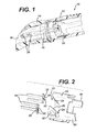
FIG. 3 is an enlarged perspective view of one of the components shown inFIG. 2 , rotated to a different position. -
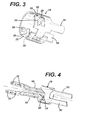
FIG. 4 is a perspective view showing the components ofFIG. 2 in an assembled state. -
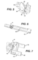
FIG. 5 is an enlarged detail view of a portion of the assembly shown inFIG. 4 . -
FIG. 6 is a perspective view showing one of the components ofFIG. 2 assembled with a further sub-assembly. -
FIG. 7 is an enlarged detail view of a portion of the assembly shown inFIG. 6 . - Like reference symbols in the various drawings indicate like elements.
- Referring to
FIG. 1 , a battery powereddevice 10 includes acylindrical housing 12 and a generallycylindrical battery cover 14. Thebattery cover 14 is mounted on thehousing 12 by the connection of one or more metal spring element(s) 16 to a generally cylindricalmetal receiving part 18.Spring elements 16 and receivingpart 18 will not be discussed in detail, with reference toFIGS. 2-4 . - Two spring elements are shown in
FIGS. 2-4 . However, more or fewer may be used, as will be understood by those skilled in the art. Generally, the more spring elements used, the higher the electrical reliability and the stronger the connection between the battery cover and the housing. - Referring to
FIG. 2 , eachspring element 16 has ahook 20 at one end. Each hook includes one ormore protrusions 22. The hooks are constructed to be received and retained incorresponding slots 24 in thereceiving part 18, as shown inFIGS. 1 ,4 and5 , withprotrusions 22 facilitating insertion, removal, and retention of the hooks. Eachslot 24 includes a lead-in 25 havingangled walls - The spring elements are designed to apply a spring force axially along the long axis of the housing. In the embodiment shown, the S-shaped profile of the springs (
Fig. 4 ), along with stretching of the springs during operation, generates this spring force. Thus, as the spring element moves into the slot it is stretched, pulling the battery cover and housing together. This resilient engagement of the battery cover with the housing compensates for non-linear seam lines between the battery cover and housing and other geometry issues such as tolerances. - The spring members and the receiving part are both made of metal, and thus engagement of the hooks with the slots also provides electrical contact between the spring members and the receiving part. The receiving part is in turn in electrical contact with circuitry of the device, as will be discussed below, and the battery is in contact with the spring members, and thus contact of the spring members and electrical part ultimately results in contact between the battery and the circuitry of the device. Accordingly, the spring function of the spring elements is also advantageous because it serves to provide solid and reliable electrical contact between the spring elements and the receiving part.
- The spring members and receiving part are easily assembled into the device. The spring members are retained permanently on the battery cover by press-fitting
protrusions 34 on theinner wall 36 of the battery cover into slottedopenings 32 on each spring member (seeFIGS. 1 and4 ). The receivingpart 18 is retained permanently in thehousing 12 by engagement ofundercuts 30 on the receiving part with corresponding undercuts (not shown) on the inner wall ofhousing 12. The engagement of the receiving part and housing is achieved by a spring action of the receiving part. The receiving part has a diameter that, in an uncompressed state, is greater than the inner diameter of thehousing 12. During assembly, the receiving part is compressed until its outer diameter, including undercuts 30, is less than the inner diameter of thehousing 12. The receiving part is then inserted into the housing, and allowed to spring back to its normal, uncompressed diameter. If desired, the receiving part can be heated, e.g., by inductive heating, prior to insertion into the housing, so that the hot undercuts will dig themselves into the plastic of the housing as the receiving part springs back to its uncompressed state. - Preferably, the
undercuts 30 are relatively close to theslots 20, and more preferably are axially aligned therewith, as shown. Alignment of the undercuts with the slots allows forces applied to the slot during and subsequent to closing to be transmitted directly to the attachment points of the receiving part (the undercuts). This arrangement provides an assembly that is very rigid and that is relatively insensitive to tolerances. - Referring now to
FIGS. 6 and 7 , the receivingpart 18 may be used to make electrical connection with a sub-assembly A, for instance a device that causes the appliance to vibrate. In this case, the receivingpart 18 includesarms 50 which act as power rails, providing an electrical connection to sub-assembly A. Eacharm 50 includes aterminal hook 52, which engages a corresponding structure on sub-assembly A (FIG. 7 ), typically by press-fitting or snapping the hooks into a groove or recess of the sub-assembly. As is the case with the engagement of the spring elements with the receiving part, discussed above, the engagement of thehooks 52 with the sub-assembly A serves two functions: (a) mechanically securing the sub-assembly in place, and (b) providing electrical connection between the arms 50 (and ultimately the battery) and the sub-assembly A. This dual functionality reduces the number of parts required, saves space, and simplifies assembly of the appliance. - A number of embodiments of the invention have been described. Nevertheless, it will be understood that various modifications may be made without departing from the spirit and scope of the invention. For example, while razors and toothbrushes are mentioned above, the closing systems discussed herein may be used with many other types of appliances, for example flashlights, battery powered scrub-brushes, and cameras. Moreover, while in the embodiments shown in the figures, the battery cover carries a "male" engagement member and the housing carries a corresponding "female" engagement member, this arrangement may be reversed so that the battery cover carries the female engagement member and the housing carries the male engagement member, or other types of cooperative engagement may be used. Accordingly, other embodiments are within the scope of the following claims.
- The dimensions and values disclosed herein are not to be understood as being strictly limited to the exact numerical values recited. Instead, unless otherwise specified, each such dimension is intended to mea both the recited value and functionally equivalent range surrounding that value. For example, a dimension disclosed as "40 mm" is intended to mean "about 40 mm".
Claims (16)
- A battery operated appliance comprising
a housing defining a chamber having an interior wall,
electronics within the chamber,
a battery cover, the battery cover and/or the housing being configured to contain one or more batteries, and
a closing system, including a first electrically conductive member secured to the battery cover, and a second electrically conductive member secured to the interior wall of the housing and configured to engage the first electrically conductive member and thereby mechanically secure the battery cover to the housing while also establishing electrical contact between the first and second electrically conductive members. - The appliance of claim 1 wherein the first and second electrically conductive members are configured to engage each other by rotation of the battery cover relative to the housing.
- The appliance of claim 2 wherein the second electrically conductive member includes a circumferentially extending slot having an open end and the first electrically conductive member includes a hook configured to slide into the slot through the open end during rotation.
- The appliance of claim 1, 2 or 3 wherein the interior wall of the housing is generally cylindrical.
- The appliance of claim 1 wherein outer surfaces of the housing and battery cover are generally cylindrical.
- The appliance of claim 1 wherein the first electrically conductive member includes a spring element configured to apply an axial force between the housing and battery cover when the first and second electrically conductive members are engaged.
- The appliance of claim 6 wherein the first electrically conductive member includes two or more spring elements.
- The appliance of claim 7 wherein each spring element provides an electrical contact between the first and second electrically conductive members.
- The appliance of claim 1 wherein the first and second electrically conductive members are secured to the battery cover and housing, respectively, by a snap fit.
- The appliance of claim 1 wherein the second electrically conductive member includes a portion configured to make electrical contact with an electronic sub-assembly of the appliance.
- The appliance of claim 10 wherein the portion comprises one or more power rails.
- The appliance of claim 11 wherein each power rail includes a clip constructed to engage the sub-assembly.
- The appliance of claim 12 wherein each clip is configured to mechanically secure the second electrically conductive member to the sub-assembly.
- The appliance of claim 9 wherein the second electrically conductive element includes one or more undercuts configured to engage corresponding undercuts on the interior wall of the housing.
- The appliance of claim 14 wherein the second electrically conductive member includes engagement regions configured for mechanical engagement with corresponding regions on the first electrically conductive member, and each undercut on the second electrically conductive element is generally axially aligned with one of the engagement regions.
- The appliance of claim 3 wherein the open end of the slot includes a lead-in configured to guide insertion of the hook into the slot.
Applications Claiming Priority (2)
| Application Number | Priority Date | Filing Date | Title |
|---|---|---|---|
| US11/115,885 US7694419B2 (en) | 2005-04-27 | 2005-04-27 | Battery-operated appliances |
| EP06740813.8A EP1875531B2 (en) | 2005-04-27 | 2006-04-11 | Battery-operated appliances |
Related Parent Applications (2)
| Application Number | Title | Priority Date | Filing Date |
|---|---|---|---|
| EP06740813.8A Division-Into EP1875531B2 (en) | 2005-04-27 | 2006-04-11 | Battery-operated appliances |
| EP06740813.8 Division | 2006-04-11 |
Publications (1)
| Publication Number | Publication Date |
|---|---|
| EP2221902A1 true EP2221902A1 (en) | 2010-08-25 |
Family
ID=36759014
Family Applications (2)
| Application Number | Title | Priority Date | Filing Date |
|---|---|---|---|
| EP06740813.8A Active EP1875531B2 (en) | 2005-04-27 | 2006-04-11 | Battery-operated appliances |
| EP10162831A Withdrawn EP2221902A1 (en) | 2005-04-27 | 2006-04-11 | Battery operated appliances |
Family Applications Before (1)
| Application Number | Title | Priority Date | Filing Date |
|---|---|---|---|
| EP06740813.8A Active EP1875531B2 (en) | 2005-04-27 | 2006-04-11 | Battery-operated appliances |
Country Status (14)
| Country | Link |
|---|---|
| US (3) | US7694419B2 (en) |
| EP (2) | EP1875531B2 (en) |
| JP (1) | JP5384101B2 (en) |
| KR (1) | KR100962729B1 (en) |
| CN (1) | CN101167199B (en) |
| AT (1) | ATE468619T1 (en) |
| BR (1) | BRPI0611149B1 (en) |
| CA (1) | CA2605495C (en) |
| DE (2) | DE602006014387D1 (en) |
| ES (1) | ES2345783T5 (en) |
| MX (1) | MX2007013344A (en) |
| PL (1) | PL1875531T5 (en) |
| RU (1) | RU2384917C2 (en) |
| WO (1) | WO2006115757A1 (en) |
Cited By (1)
| Publication number | Priority date | Publication date | Assignee | Title |
|---|---|---|---|---|
| US11440176B2 (en) | 2017-01-24 | 2022-09-13 | Techtronic Cordless Gp | Battery terminal holder for electric tools |
Families Citing this family (18)
| Publication number | Priority date | Publication date | Assignee | Title |
|---|---|---|---|---|
| US20070050995A1 (en) * | 2005-09-06 | 2007-03-08 | Fred Schnak | Razors |
| US7637014B2 (en) * | 2005-09-06 | 2009-12-29 | The Gillette Company | Razors |
| TWI311273B (en) * | 2006-03-07 | 2009-06-21 | Primax Electronics Ltd | Wireless mouse |
| US7484982B1 (en) | 2007-08-31 | 2009-02-03 | The Gillette Company | Coupling for a hand held appliance |
| JP5504139B2 (en) * | 2010-11-18 | 2014-05-28 | パナソニック株式会社 | Small electric device |
| ITTO20120679A1 (en) * | 2012-07-31 | 2014-02-01 | Aquilino Giovanni | SUSPENSION DEVICE FOR AN ELECTRIC LIGHTING APPLIANCE |
| RU2610573C2 (en) * | 2012-11-01 | 2017-02-13 | Дзе Жиллетт Компани | Shaving device, operating from battery |
| MX2015013588A (en) * | 2013-03-26 | 2016-02-05 | Gillette Co | Retarding mechanism. |
| CN104540076B (en) * | 2014-11-20 | 2018-09-07 | 歌尔股份有限公司 | Loud speaker module |
| JP6665199B2 (en) | 2015-05-27 | 2020-03-13 | コーニンクレッカ フィリップス エヌ ヴェKoninklijke Philips N.V. | Battery chassis with stroke limiter design |
| WO2017120610A2 (en) * | 2016-01-10 | 2017-07-13 | Walker & Co. Brands, Inc. | Trimmer device with an adjustable cutting assembly |
| USD794871S1 (en) | 2016-01-15 | 2017-08-15 | Medline Industries, Inc. | Clipper |
| USD795497S1 (en) | 2016-01-15 | 2017-08-22 | Medline Industries, Inc. | Clipper |
| JP6653766B2 (en) | 2016-03-22 | 2020-02-26 | コーニンクレッカ フィリップス エヌ ヴェKoninklijke Philips N.V. | Safety switch device for personal care equipment |
| USD802214S1 (en) | 2016-06-10 | 2017-11-07 | Medline Industries, Inc. | Clipper head |
| USD802217S1 (en) | 2016-06-10 | 2017-11-07 | Medline Industries, Inc. | Clipper head |
| USD802215S1 (en) | 2016-06-10 | 2017-11-07 | Medline Industries, Inc. | Clipper head |
| USD802216S1 (en) | 2016-06-10 | 2017-11-07 | Medline Industries, Inc. | Clipper head |
Citations (10)
| Publication number | Priority date | Publication date | Assignee | Title |
|---|---|---|---|---|
| US4398238A (en) * | 1981-12-04 | 1983-08-09 | Kel-Lite Industries, Inc. | Variable focus flashlight |
| US5122427A (en) * | 1991-08-09 | 1992-06-16 | Skil Corporation | Battery pack |
| US5158357A (en) * | 1990-09-11 | 1992-10-27 | Mcdermott Kevin | Flashlight of selectable colors |
| JPH08117258A (en) * | 1994-10-24 | 1996-05-14 | Purakon:Kk | Electric toothbrush |
| US5947912A (en) * | 1997-09-10 | 1999-09-07 | Oralgiene | Vibratory tongue conditioning implement |
| WO2001082825A1 (en) * | 2000-04-27 | 2001-11-08 | Glaxosmithkline Consumer Healthcare Gmbh & Co Kg | Toothbrush |
| US20020124333A1 (en) * | 1999-10-19 | 2002-09-12 | Trisa Holding | Toothbrush having a vibrating head part |
| US20030037391A1 (en) * | 2000-02-09 | 2003-02-27 | Philipp Pfenniger | Method for producing a hollow handle for a teeth cleaning device |
| US20040095759A1 (en) * | 2000-05-31 | 2004-05-20 | Koch Greg W. | Flashlight and flashlight electrical connectors |
| US6777890B1 (en) * | 2003-06-20 | 2004-08-17 | Chin-Lin Huang | Cylindrical miniature-LED light-emitting device |
Family Cites Families (175)
| Publication number | Priority date | Publication date | Assignee | Title |
|---|---|---|---|---|
| US1180686A (en) † | 1913-06-07 | 1916-04-25 | Katherine E Allport | Illuminated razor. |
| US1187103A (en) | 1915-12-18 | 1916-06-13 | Interstate Electric Novelty Company | Casing for portable electric flash-lights. |
| US1393858A (en) † | 1919-11-12 | 1921-10-18 | Maurice Hartman | Portable electric light |
| US1514314A (en) † | 1921-04-04 | 1924-11-04 | Harry A Douglas | Circuit-continuing device |
| US1618939A (en) | 1923-05-21 | 1927-02-22 | Edward F Marth | Electrical receptacle |
| US1990504A (en) | 1933-06-03 | 1935-02-12 | Bond Electric Corp | Flash light |
| US2234972A (en) | 1934-04-30 | 1941-03-18 | William M Lennan | Flashlight |
| US2235714A (en) † | 1936-04-13 | 1941-03-18 | William M Lennan | Flashlight |
| US2310409A (en) | 1941-05-07 | 1943-02-09 | Martin M Ellman | Dental burr and hand-piece assembly |
| US2478325A (en) † | 1947-06-13 | 1949-08-09 | Alfred P Russell | Illuminating attachment for canes or the like |
| US2626299A (en) | 1949-05-10 | 1953-01-20 | Kingston Products Corp | Waterproof receptacle |
| US2648762A (en) † | 1950-12-16 | 1953-08-11 | Milton S Dunkelberger | Combined housing and flexible flashlight support |
| US2704356A (en) | 1951-01-13 | 1955-03-15 | Wade Electric Products Co | Electrical connector |
| US2951108A (en) | 1956-04-23 | 1960-08-30 | Int Electronic Res Corp | Tube shield and base assembly |
| US2963598A (en) | 1957-12-05 | 1960-12-06 | Allen H Kent | Driving means |
| US2993948A (en) | 1958-10-01 | 1961-07-25 | Phillips Petroleum Co | Cell container structure |
| US3070748A (en) | 1961-04-14 | 1962-12-25 | Motorola Inc | Portable radio receiver having inter-changeable means for using single-use and rechargeable batteries |
| US3104405A (en) | 1961-06-29 | 1963-09-24 | Roger P Perrinjaquet | Tooth brush actuating mechanism |
| DE1204187B (en) | 1962-04-28 | 1965-11-04 | Otto Huebner | Powered toothbrush |
| CH459320A (en) | 1964-10-06 | 1968-07-15 | Ingvar Nodfelt Nils | Non-replaceable line coupling |
| US3346748A (en) | 1965-06-07 | 1967-10-10 | Songrand Corp | Vibrator motor with self-contained cooling means |
| US3358309A (en) | 1965-12-27 | 1967-12-19 | Empire Brushes Inc | Cordless electric vibrating hair brush, or like vibrating manipulators |
| US3550280A (en) | 1966-07-18 | 1970-12-29 | Oster Mfg Co John | Hair clipper |
| US3451391A (en) | 1968-03-25 | 1969-06-24 | Jon H Tavel | Cordless electric vibrator for use on the human body |
| CH490941A (en) † | 1968-05-29 | 1970-05-31 | Belz August | Dry shaver |
| US3609632A (en) | 1968-08-19 | 1971-09-28 | Trw Inc | Releasable electrical connector |
| DE1782586A1 (en) | 1968-09-20 | 1971-10-14 | Bosch Gmbh Robert | Manicure device |
| US3602217A (en) | 1969-04-15 | 1971-08-31 | Richard Dupont | Eye treatment device |
| US3636627A (en) | 1969-08-11 | 1972-01-25 | Victor Tiffin | Razor with oscillating head |
| US3685080A (en) | 1969-08-28 | 1972-08-22 | Huebner Otto | Mechanically powered toothbrush |
| US3623481A (en) | 1970-07-30 | 1971-11-30 | William S Curran | Gum massage implement and method of finger massaging gums |
| US3702487A (en) | 1971-03-29 | 1972-11-14 | Thomas Sung | Circularly sweeping toothbrush |
| US3705578A (en) | 1971-07-15 | 1972-12-12 | Vibra Baths Home Products Inc | Waterproof battery operated vibrator |
| US3779238A (en) | 1972-06-29 | 1973-12-18 | Vibra Spa Products Inc | Waterproof battery operated vibrator |
| US3887393A (en) | 1972-12-15 | 1975-06-03 | Bell & Howell Co | Battery holder assembly |
| US4004344A (en) | 1974-09-06 | 1977-01-25 | Gold Gary K | Dental device |
| US3945702A (en) | 1974-10-15 | 1976-03-23 | Leviton Manufacturing Co., Inc. | Twist-type electrical connector with safety interlock |
| US3967617A (en) | 1974-11-25 | 1976-07-06 | Alston, Inc. | Mechanical gum massager |
| US3945076A (en) | 1974-12-10 | 1976-03-23 | Thomas Sung | Circular toothbrush |
| CH594296A5 (en) † | 1975-10-21 | 1978-01-13 | Schurter Ag H | |
| US4053688A (en) | 1975-12-08 | 1977-10-11 | Perkins Carroll R | Battery holder |
| US4027348A (en) | 1976-01-12 | 1977-06-07 | Sperry Rand Corporation | Skin treatment appliance |
| US4103694A (en) | 1976-05-06 | 1978-08-01 | Clairol, Inc. | Manicuring unit |
| US4213078A (en) | 1976-07-26 | 1980-07-15 | General Electric Company | Battery holder and connector for a radio receiver or the like |
| US4183140A (en) | 1977-05-31 | 1980-01-15 | Concept Inc. | Dental stain remover |
| US4149530A (en) | 1977-06-07 | 1979-04-17 | Gow Quinn W | Electric massager |
| US4175299A (en) | 1977-11-07 | 1979-11-27 | Sempliner Arthur T | Power toothbrush or the like with orbital brush action |
| US4276672A (en) | 1977-11-07 | 1981-07-07 | Teague Jr Walter D | Power toothbrush or the like with orbital brush action |
| CH625687A5 (en) | 1978-01-20 | 1981-10-15 | Gimelli & Co Ag | Electric toothbrush with oscillating armature motor for mains power supply |
| US4220985A (en) | 1978-02-03 | 1980-09-02 | Hiroshi Hukuba | Illumination device |
| US4236889A (en) | 1978-03-28 | 1980-12-02 | Wright Winston F | Dental cleaning device |
| US4213471A (en) | 1978-05-15 | 1980-07-22 | Clairol, Inc | Manicuring unit |
| US4203221A (en) | 1978-09-29 | 1980-05-20 | Syntex (U.S.A.) Inc. | Gas-driven handpiece having vibration isolating means |
| GB2042787A (en) | 1979-02-26 | 1980-09-24 | Emerald Electronics Ltd | Improved battery |
| US4336622A (en) | 1979-08-29 | 1982-06-29 | Teague Jr Walter D | Power toothbrush or the like with orbital brush action |
| US4377877A (en) | 1980-01-08 | 1983-03-29 | Rourke James L O | Power driven rotary toothbrush with automatic flossing means |
| DE3022102C1 (en) | 1980-06-12 | 1981-11-26 | Georg Dipl.-Ing. Dr.-Ing. 8152 Feldkirchen-Westerham Spinner | RF coaxial connector |
| US4447749A (en) | 1981-07-29 | 1984-05-08 | Black & Decker Inc. | Cordless electric device having contact increasing means |
| US4390225A (en) | 1981-08-06 | 1983-06-28 | Bell Telephone Laboratories, Incorporated | Fuse block assembly |
| US4479516A (en) | 1982-02-08 | 1984-10-30 | Hunter Frank M | Electrically driven toothbrush |
| US4495551A (en) | 1983-08-17 | 1985-01-22 | Halkey-Roberts Corporation | Conductor tube for flashlights |
| JPS6131433U (en) | 1984-07-30 | 1986-02-25 | 市川プレス工業株式会社 | portable massager |
| US4563728A (en) | 1984-08-27 | 1986-01-07 | Wonder Corporation Of America | Pen light with abutting contact clip |
| US4656565A (en) | 1984-09-06 | 1987-04-07 | Mag Instrument, Inc. | Flashlight |
| US4845795A (en) | 1985-06-10 | 1989-07-11 | Dental Research Corporation | Automatic cleaning device |
| US4644244A (en) | 1985-08-30 | 1987-02-17 | Kittelson Clifford E | Battery conditioner |
| US4751452A (en) | 1986-02-24 | 1988-06-14 | Cooper Industries | Battery operated power wrap tool |
| US4724563A (en) | 1986-04-16 | 1988-02-16 | Fry Raymond A | Personal care power brush |
| JPH0784636B2 (en) * | 1986-09-12 | 1995-09-13 | マツダ株式会社 | Hydrogen storage alloy |
| US5071348A (en) | 1986-11-28 | 1991-12-10 | Les Produits Associates Lpa-Broxo S.A. | Brush and masseur for interproximal dental cleaning |
| US4806440A (en) | 1987-02-05 | 1989-02-21 | Cni | Lantern battery substitute |
| US4835410A (en) | 1988-02-26 | 1989-05-30 | Black & Decker Inc. | Dual-mode corded/cordless system for power-operated devices |
| US4913133A (en) | 1988-06-28 | 1990-04-03 | Edward Tichy | Hand held periodontic tool |
| US4924358A (en) | 1988-09-12 | 1990-05-08 | Inventech Licensing Co. | Safety-sparkler wand w/chemiluminescent or electric-light illumination |
| US5006073A (en) † | 1989-05-30 | 1991-04-09 | Motorola, Inc. | Snap fit contact assembly |
| US5000684A (en) | 1989-08-10 | 1991-03-19 | Ronald Odrich | Supra and subgingival tooth cleaning apparatus and method |
| DE3937875A1 (en) | 1989-11-14 | 1991-05-16 | Braun Ag | ELECTRICALLY OPERATED ORAL CARE DEVICE |
| US5007169A (en) † | 1989-12-11 | 1991-04-16 | Warner-Lambert Company | Vibrating razor |
| US5165131A (en) | 1989-12-29 | 1992-11-24 | Staar Development Co., S.A. | Teeth cleaning apparatus |
| US5033150A (en) | 1990-01-29 | 1991-07-23 | Product Development (S.G.Z.) Ltd. | Motor-driven toothbrush |
| US5088145A (en) | 1990-03-26 | 1992-02-18 | Whitefield Robert O | Electrically powered toothbrush |
| US5123841A (en) | 1990-04-02 | 1992-06-23 | Millner Don E | Interproximal dental plaque remover |
| US5267579A (en) | 1990-06-22 | 1993-12-07 | Bushberger Todd E | Oscillating flossing implement |
| US5299354A (en) | 1990-10-11 | 1994-04-05 | The Gillette Company | Oscillating shaver |
| GB2250428B (en) | 1990-12-03 | 1994-07-27 | Solar Wide Ind Ltd | Vibrating toothbrush |
| CN2087500U (en) | 1991-02-05 | 1991-10-30 | 毕日恒 | Sway type automatic toothbrush |
| US5062211A (en) † | 1991-03-04 | 1991-11-05 | Amico Paul A Di | Motorized twisting pasta fork |
| US5546624A (en) | 1991-03-25 | 1996-08-20 | Sonex International Corporation | Apparatus to selectively couple ultransonic energy in a therapeutic ultransonic toothbrush |
| US5138733A (en) | 1991-03-25 | 1992-08-18 | Sonex International Corporation | Ultrasonic toothbrush |
| GB2255901B (en) | 1991-05-21 | 1995-07-19 | Appealing Appliances Co Ltd | Electric toothbrush holder |
| US5378153A (en) | 1992-02-07 | 1995-01-03 | Gemtech, Inc. | High performance acoustical cleaning apparatus for teeth |
| US5160194A (en) | 1992-02-27 | 1992-11-03 | Feldman Melvin D | Toothbrush with externally illuminated bristles |
| US5253382A (en) | 1992-08-31 | 1993-10-19 | Janos Beny | Power operated toothbrush |
| US5234355A (en) | 1992-09-11 | 1993-08-10 | Heyco Stamped Products, Inc. | Premold for a twist locking female connector |
| US5259083A (en) | 1992-09-24 | 1993-11-09 | 1008335 Ontario Inc. | Mechanical toothbrush |
| AU674714B2 (en) | 1992-10-31 | 1997-01-09 | Masanori Sato | Toothbrush and electric toothbrush |
| US5573020A (en) | 1993-01-07 | 1996-11-12 | Robinson; Dane Q. | Dental flossing device and method therefor |
| JP2668631B2 (en) | 1993-03-19 | 1997-10-27 | 英二 岡田 | Method for brushing an electric toothbrush having a predetermined frequency |
| CN100376047C (en) | 1993-04-05 | 2008-03-19 | 布莱克和戴克公司 | Battery pack for cordless device |
| US5311632A (en) | 1993-05-12 | 1994-05-17 | Center Leslie T | Ultrasonic plaque removal device |
| CA2163752C (en) | 1993-05-27 | 2001-08-07 | Tomohisa Sugimoto | Oral hygiene instrument |
| US5493747A (en) | 1993-07-27 | 1996-02-27 | Matsushita Electric Works, Ltd. | Electric toothbrush |
| US5476729A (en) | 1993-08-18 | 1995-12-19 | Invisible Fence Company, Inc. | Electronic device having a removable battery pack assembly |
| US5445900A (en) | 1993-08-18 | 1995-08-29 | Invisible Fence Company, Inc. | Electronic device having a removable battery pack assembly |
| US5353460A (en) | 1993-09-24 | 1994-10-11 | Ohio Health Care Products, Inc. | Power driven toothbrush |
| DE4336088C1 (en) * | 1993-10-22 | 1995-01-26 | Braun Ag | Battery-operated small appliance for personal use |
| JPH07220704A (en) * | 1994-01-28 | 1995-08-18 | Seikosha Co Ltd | Battery power unit of cylindrical electric equipment |
| US5561881A (en) | 1994-03-22 | 1996-10-08 | U.S. Philips Corporation | Electric toothbrush |
| US5438726A (en) | 1994-05-09 | 1995-08-08 | Leite; Francisca P. | Tooth cleaning system with timer and signaling means |
| JP2854983B2 (en) | 1994-06-06 | 1999-02-10 | テレダイン・ウォーター・ピック・ディビジョン・オブ・テレダイン・インダストリーズ・インコーポレーテッド | High frequency electric toothbrush |
| EP0691107A1 (en) | 1994-06-10 | 1996-01-10 | Kitano Co., Ltd. | Electric toothbrush |
| US5435033A (en) | 1994-07-18 | 1995-07-25 | Millner; Don E. | Interdental toothcleaner holder |
| US5681667A (en) | 1994-08-11 | 1997-10-28 | Black & Decker Inc. | Battery pack retaining latch for cordless device |
| US5504961A (en) | 1994-08-16 | 1996-04-09 | Yang; C. S. | Electric toothbrush with drive release |
| US5471695A (en) | 1994-08-31 | 1995-12-05 | Aiyar; Sanjay | Motorized brush |
| US5544382A (en) | 1994-09-14 | 1996-08-13 | Optiva Corp. | Pacing toothbrush |
| US5511270A (en) | 1994-10-26 | 1996-04-30 | Eliachar; Eliahu | Hair brush |
| DE4439835C1 (en) | 1994-11-08 | 1996-02-08 | Braun Ag | Electric tooth brush with polishing duration display |
| US5544415A (en) * | 1994-12-06 | 1996-08-13 | Kunnex Incorporated | Water-proof and washable electric razor |
| US5524312A (en) | 1995-03-06 | 1996-06-11 | Tan; Kuo-Ching | Electric toothbrush |
| US6050818A (en) | 1995-04-21 | 2000-04-18 | Braun Aktiengesellschaft | Electrically powered dental cleansing apparatus |
| US5625916A (en) | 1995-05-24 | 1997-05-06 | Mcdougall; Greg | Toothbrush |
| US5601359A (en) | 1995-05-25 | 1997-02-11 | Streamlight, Inc. | Flashlight having resilient sleeve |
| US5784742A (en) | 1995-06-23 | 1998-07-28 | Optiva Corporation | Toothbrush with adaptive load sensor |
| US5706542A (en) | 1995-06-27 | 1998-01-13 | Okada; Eiji | Electrically driven toothbrush |
| US5617602A (en) | 1995-06-27 | 1997-04-08 | Okada; Eiji | Motor-driven toothbrush |
| JP3264607B2 (en) | 1995-07-28 | 2002-03-11 | 株式会社モリタ製作所 | Motor control device for dental handpiece |
| DE29515288U1 (en) | 1995-09-23 | 1995-11-23 | Rowenta Werke Gmbh | Electric toothbrush |
| US5622192A (en) | 1995-12-05 | 1997-04-22 | Chiou; Shih-Kuen | Comb having spraying and massaging devices |
| US5640979A (en) | 1995-12-22 | 1997-06-24 | Trenary; Don C. | Finger nail cleaner assembly with a rotating brush |
| US5822821A (en) | 1996-01-12 | 1998-10-20 | Pentalpha Enterprises Ltd. | Electric toothbrush |
| US5642931A (en) | 1996-01-18 | 1997-07-01 | Taxiwand Inc. | Taxi wand |
| US5794295A (en) | 1996-03-11 | 1998-08-18 | Shen; Chung-Shan | Electrically operated oscillatory toothbrush |
| WO1997034710A1 (en) | 1996-03-21 | 1997-09-25 | Sunstar Inc. | Vibration generating device and oral hygiene device using same |
| US5706541A (en) | 1996-04-29 | 1998-01-13 | Black & Decker Inc. | Watertight friction fit battery cap with cam removal |
| US5770328A (en) | 1996-07-05 | 1998-06-23 | Motorola, Inc. | Battery packaging system and clip for same |
| US5738575A (en) | 1996-08-30 | 1998-04-14 | Bock; Robert T. | Orbitally vibrating method and apparatus for interproximal plaque removal |
| US5827064A (en) | 1996-08-30 | 1998-10-27 | Sonex International Corp. | Orbitally or reciprocally vibrating method for interproximal plaque removal |
| CN1124829C (en) | 1996-12-17 | 2003-10-22 | 皇家菲利浦电子有限公司 | Toothbrush having a brush holder movable against spring force |
| DE19654319C1 (en) | 1996-12-24 | 1998-08-06 | Rowenta Werke Gmbh | Electric toothbrush |
| US5784743A (en) | 1996-12-30 | 1998-07-28 | Addway Engineering Limited | Electric toothbrushes |
| US5857233A (en) | 1997-02-27 | 1999-01-12 | Wynn; Emery G. | Body lotion applicator |
| FR2762716B1 (en) | 1997-04-28 | 1999-05-28 | Alsthom Cge Alcatel | DEVICE FOR ASSEMBLING BATTERIES OF ELECTROCHEMICAL GENERATORS |
| DK0925004T3 (en) | 1997-07-16 | 2002-08-26 | Trisa Buerstenfabrik Ag | Applying part to a motor, especially electric motor driven toothbrush |
| TW389684B (en) | 1998-08-20 | 2000-05-11 | Luo De Liang | Portable electric cleaning device |
| US6000083A (en) | 1998-09-30 | 1999-12-14 | Dr. Johns Products, Ltd. | Electric toothbrush |
| US6178579B1 (en) | 1998-09-30 | 2001-01-30 | Dr. Johns Products, Ltd. | Electric toothbrush |
| DE19900765A1 (en) | 1999-01-12 | 2000-07-13 | Braun Gmbh | Device for removing plaques and for cleaning interdental spaces |
| US6202242B1 (en) | 1999-01-29 | 2001-03-20 | Zephyr Design, Inc. | Light emitting electric toothbrush |
| US6139359A (en) | 1999-04-08 | 2000-10-31 | Snap-On Tools Company | Cordless screwdriver and multi-position battery pack therefor |
| US6138310A (en) | 1999-04-23 | 2000-10-31 | Porper; Robert P. | Electric toothbrush having opposed bristle heads |
| US6401288B1 (en) | 1999-04-23 | 2002-06-11 | Robert P. Porper | Mechanical toothbrush with opposed dual heads and having oscillatory movement |
| US6226068B1 (en) | 1999-08-27 | 2001-05-01 | Amphenol Corporation | Self-locking bayonet coupling mechanism |
| DE10003924A1 (en) * | 2000-01-29 | 2001-08-02 | Zahnradfabrik Friedrichshafen | Electrical connector |
| US6347425B1 (en) | 2000-06-28 | 2002-02-19 | Colgate-Palmolive Company | Powered toothbrush having three dimensional rotational head motion |
| US6936375B2 (en) | 2000-10-12 | 2005-08-30 | Fuji Photo Film, Co., Ltd. | Battery unit for lens-fitted photo film unit |
| JP2002208387A (en) * | 2001-01-12 | 2002-07-26 | Olympus Optical Co Ltd | Battery storage device and camera |
| US6920659B2 (en) | 2001-01-12 | 2005-07-26 | Water Pik, Inc. | Toothbrush |
| JP2002245996A (en) | 2001-02-20 | 2002-08-30 | Sony Corp | Battery accommodation case |
| US20020178519A1 (en) | 2001-05-16 | 2002-12-05 | Vincent Zarlengo | Electric tooth flossing and brushing apparatus |
| US6921283B2 (en) | 2001-08-27 | 2005-07-26 | Trompeter Electronics, Inc. | BNC connector having visual indication |
| US6725490B2 (en) | 2001-11-06 | 2004-04-27 | The Procter & Gamble Company | Complex motion toothbrush |
| US20030196283A1 (en) | 2002-04-23 | 2003-10-23 | Eyal Eliav | Powered toothbrush |
| US20030226223A1 (en) | 2002-06-11 | 2003-12-11 | The Procter & Gamble Co. | High efficiency electric toothbrush |
| JP3855870B2 (en) | 2002-07-16 | 2006-12-13 | 松下電器産業株式会社 | Portable power system |
| US7086886B2 (en) | 2002-07-23 | 2006-08-08 | Alden Products Company | Reinforced locking connector |
| US7137163B2 (en) | 2002-09-27 | 2006-11-21 | Colgate-Palmolive Company | Power toothbrush and power source |
| DE10245086A1 (en) | 2002-09-27 | 2004-04-08 | Trisa Holding Ag | Method of making a toothbrush |
| US6966093B2 (en) | 2002-09-27 | 2005-11-22 | Colgate-Polmolive Company | Toothbrush having a movable upstanding cleaning element |
| US7140058B2 (en) | 2002-09-27 | 2006-11-28 | Colgate-Palmolive Company | Toothbrush with kinetic plate |
| EP1563967A1 (en) | 2004-02-11 | 2005-08-17 | Eveready Battery Company, Inc. | Shaver and method of manufacturing a shaver |
| US7465114B2 (en) | 2004-08-11 | 2008-12-16 | Elc Management Llc | Vibrating mascara applicator, suitable compositions and method of use |
| CN2755427Y (en) * | 2004-12-15 | 2006-02-01 | 黄纪超 | Switch structure of LED electric torch |
| US7637014B2 (en) | 2005-09-06 | 2009-12-29 | The Gillette Company | Razors |
| US20070050995A1 (en) | 2005-09-06 | 2007-03-08 | Fred Schnak | Razors |
-
2005
- 2005-04-27 US US11/115,885 patent/US7694419B2/en active Active
-
2006
- 2006-04-11 CN CN2006800141662A patent/CN101167199B/en not_active Expired - Fee Related
- 2006-04-11 KR KR1020077024437A patent/KR100962729B1/en not_active IP Right Cessation
- 2006-04-11 DE DE602006014387T patent/DE602006014387D1/en active Active
- 2006-04-11 WO PCT/US2006/013336 patent/WO2006115757A1/en active Application Filing
- 2006-04-11 AT AT06740813T patent/ATE468619T1/en not_active IP Right Cessation
- 2006-04-11 DE DE202006020861U patent/DE202006020861U1/en not_active Expired - Lifetime
- 2006-04-11 BR BRPI0611149-1A patent/BRPI0611149B1/en not_active IP Right Cessation
- 2006-04-11 MX MX2007013344A patent/MX2007013344A/en active IP Right Grant
- 2006-04-11 CA CA2605495A patent/CA2605495C/en not_active Expired - Fee Related
- 2006-04-11 PL PL06740813T patent/PL1875531T5/en unknown
- 2006-04-11 JP JP2008508890A patent/JP5384101B2/en active Active
- 2006-04-11 ES ES06740813.8T patent/ES2345783T5/en active Active
- 2006-04-11 EP EP06740813.8A patent/EP1875531B2/en active Active
- 2006-04-11 EP EP10162831A patent/EP2221902A1/en not_active Withdrawn
- 2006-04-11 RU RU2007136049/09A patent/RU2384917C2/en not_active IP Right Cessation
-
2010
- 2010-02-18 US US12/707,683 patent/US8250763B2/en active Active
-
2012
- 2012-03-22 US US13/426,996 patent/US8302316B2/en active Active
Patent Citations (10)
| Publication number | Priority date | Publication date | Assignee | Title |
|---|---|---|---|---|
| US4398238A (en) * | 1981-12-04 | 1983-08-09 | Kel-Lite Industries, Inc. | Variable focus flashlight |
| US5158357A (en) * | 1990-09-11 | 1992-10-27 | Mcdermott Kevin | Flashlight of selectable colors |
| US5122427A (en) * | 1991-08-09 | 1992-06-16 | Skil Corporation | Battery pack |
| JPH08117258A (en) * | 1994-10-24 | 1996-05-14 | Purakon:Kk | Electric toothbrush |
| US5947912A (en) * | 1997-09-10 | 1999-09-07 | Oralgiene | Vibratory tongue conditioning implement |
| US20020124333A1 (en) * | 1999-10-19 | 2002-09-12 | Trisa Holding | Toothbrush having a vibrating head part |
| US20030037391A1 (en) * | 2000-02-09 | 2003-02-27 | Philipp Pfenniger | Method for producing a hollow handle for a teeth cleaning device |
| WO2001082825A1 (en) * | 2000-04-27 | 2001-11-08 | Glaxosmithkline Consumer Healthcare Gmbh & Co Kg | Toothbrush |
| US20040095759A1 (en) * | 2000-05-31 | 2004-05-20 | Koch Greg W. | Flashlight and flashlight electrical connectors |
| US6777890B1 (en) * | 2003-06-20 | 2004-08-17 | Chin-Lin Huang | Cylindrical miniature-LED light-emitting device |
Cited By (1)
| Publication number | Priority date | Publication date | Assignee | Title |
|---|---|---|---|---|
| US11440176B2 (en) | 2017-01-24 | 2022-09-13 | Techtronic Cordless Gp | Battery terminal holder for electric tools |
Also Published As
| Publication number | Publication date |
|---|---|
| CA2605495C (en) | 2010-06-08 |
| RU2384917C2 (en) | 2010-03-20 |
| JP2008539552A (en) | 2008-11-13 |
| JP5384101B2 (en) | 2014-01-08 |
| US20060246347A1 (en) | 2006-11-02 |
| WO2006115757A1 (en) | 2006-11-02 |
| PL1875531T5 (en) | 2014-10-31 |
| DE602006014387D1 (en) | 2010-07-01 |
| MX2007013344A (en) | 2008-01-11 |
| BRPI0611149A2 (en) | 2010-08-17 |
| CA2605495A1 (en) | 2006-11-02 |
| KR20080005373A (en) | 2008-01-11 |
| EP1875531A1 (en) | 2008-01-09 |
| DE202006020861U1 (en) | 2010-07-15 |
| EP1875531B1 (en) | 2010-05-19 |
| EP1875531B2 (en) | 2014-04-09 |
| BRPI0611149B1 (en) | 2017-11-07 |
| RU2007136049A (en) | 2009-06-10 |
| CN101167199B (en) | 2010-07-21 |
| ATE468619T1 (en) | 2010-06-15 |
| US8250763B2 (en) | 2012-08-28 |
| KR100962729B1 (en) | 2010-06-09 |
| US8302316B2 (en) | 2012-11-06 |
| ES2345783T3 (en) | 2010-10-01 |
| CN101167199A (en) | 2008-04-23 |
| US20120177964A1 (en) | 2012-07-12 |
| US20100173519A1 (en) | 2010-07-08 |
| US7694419B2 (en) | 2010-04-13 |
| PL1875531T3 (en) | 2010-10-29 |
| ES2345783T5 (en) | 2014-05-13 |
Similar Documents
| Publication | Publication Date | Title |
|---|---|---|
| US7694419B2 (en) | Battery-operated appliances | |
| US6436569B1 (en) | Electrical appliance with battery holder | |
| KR101073082B1 (en) | Brush holding device in electric motor | |
| EP1253673A3 (en) | Charge contacts for rechargeable device | |
| US4083011A (en) | Battery holder and connector for a radio receiver or the like | |
| KR100349802B1 (en) | An assembly of electric motor-controlling components | |
| EP3415379B1 (en) | An alarming system for a wiper and a wiper blade assembly with alarming function | |
| JP2005045872A (en) | Brush holder in motor | |
| CN210124865U (en) | Toothbrush head and electric toothbrush | |
| EP2914405B1 (en) | Battery operated razor | |
| JP3110205U (en) | Vibrator motor housing and electrical connector | |
| JPS6037801Y2 (en) | small electrical equipment | |
| KR20060097319A (en) | Brush assembly for motor | |
| JP3543199B2 (en) | Brush equipment | |
| KR200331483Y1 (en) | A wall outlet | |
| JP2004006125A (en) | Brush device of electric motor | |
| JP2005310459A (en) | Battery incorrect insertion preventing structure in battery housing part | |
| KR19990029977U (en) | Remote control battery case |
Legal Events
| Date | Code | Title | Description |
|---|---|---|---|
| PUAI | Public reference made under article 153(3) epc to a published international application that has entered the european phase |
Free format text: ORIGINAL CODE: 0009012 |
|
| AC | Divisional application: reference to earlier application |
Ref document number: 1875531 Country of ref document: EP Kind code of ref document: P |
|
| AK | Designated contracting states |
Kind code of ref document: A1 Designated state(s): AT BE BG CH CY CZ DE DK EE ES FI FR GB GR HU IE IS IT LI LT LU LV MC NL PL PT RO SE SI SK TR |
|
| RTI1 | Title (correction) |
Free format text: BATTERY-OPERATED APPLIANCE |
|
| 17P | Request for examination filed |
Effective date: 20100908 |
|
| RAP1 | Party data changed (applicant data changed or rights of an application transferred) |
Owner name: THE GILLETTE COMPANY |
|
| 17Q | First examination report despatched |
Effective date: 20160316 |
|
| RAP1 | Party data changed (applicant data changed or rights of an application transferred) |
Owner name: THE GILLETTE COMPANY LLC |
|
| STAA | Information on the status of an ep patent application or granted ep patent |
Free format text: STATUS: THE APPLICATION IS DEEMED TO BE WITHDRAWN |
|
| 18D | Application deemed to be withdrawn |
Effective date: 20160927 |