EP2420157A1 - Toothbrush with brush topography structuring - Google Patents
Toothbrush with brush topography structuring Download PDFInfo
- Publication number
- EP2420157A1 EP2420157A1 EP10008600A EP10008600A EP2420157A1 EP 2420157 A1 EP2420157 A1 EP 2420157A1 EP 10008600 A EP10008600 A EP 10008600A EP 10008600 A EP10008600 A EP 10008600A EP 2420157 A1 EP2420157 A1 EP 2420157A1
- Authority
- EP
- European Patent Office
- Prior art keywords
- bristle
- bristles
- bundle
- pin
- toothbrush
- Prior art date
- Legal status (The legal status is an assumption and is not a legal conclusion. Google has not performed a legal analysis and makes no representation as to the accuracy of the status listed.)
- Granted
Links
Images


Classifications
-
- A—HUMAN NECESSITIES
- A46—BRUSHWARE
- A46B—BRUSHES
- A46B9/00—Arrangements of the bristles in the brush body
- A46B9/02—Position or arrangement of bristles in relation to surface of the brush body, e.g. inclined, in rows, in groups
- A46B9/04—Arranged like in or for toothbrushes
-
- A—HUMAN NECESSITIES
- A46—BRUSHWARE
- A46B—BRUSHES
- A46B3/00—Brushes characterised by the way in which the bristles are fixed or joined in or on the brush body or carrier
- A46B3/06—Brushes characterised by the way in which the bristles are fixed or joined in or on the brush body or carrier by welding together bristles made of metal wires or plastic materials
-
- A—HUMAN NECESSITIES
- A46—BRUSHWARE
- A46B—BRUSHES
- A46B9/00—Arrangements of the bristles in the brush body
- A46B9/02—Position or arrangement of bristles in relation to surface of the brush body, e.g. inclined, in rows, in groups
- A46B9/025—Position or arrangement of bristles in relation to surface of the brush body, e.g. inclined, in rows, in groups the bristles or the tufts being arranged in an angled position relative to each other
-
- A—HUMAN NECESSITIES
- A46—BRUSHWARE
- A46B—BRUSHES
- A46B9/00—Arrangements of the bristles in the brush body
- A46B9/02—Position or arrangement of bristles in relation to surface of the brush body, e.g. inclined, in rows, in groups
- A46B9/026—Position or arrangement of bristles in relation to surface of the brush body, e.g. inclined, in rows, in groups where the surface of the brush body or carrier is not in one plane, e.g. not flat
-
- A—HUMAN NECESSITIES
- A46—BRUSHWARE
- A46B—BRUSHES
- A46B9/00—Arrangements of the bristles in the brush body
- A46B9/02—Position or arrangement of bristles in relation to surface of the brush body, e.g. inclined, in rows, in groups
- A46B9/028—Bristle profile, the end of the bristle defining a surface other than a single plane or deviating from a simple geometric form, e.g. cylinder, sphere or cone
-
- A—HUMAN NECESSITIES
- A46—BRUSHWARE
- A46D—MANUFACTURE OF BRUSHES
- A46D1/00—Bristles; Selection of materials for bristles
- A46D1/02—Bristles details
- A46D1/0276—Bristles having pointed ends
-
- A—HUMAN NECESSITIES
- A46—BRUSHWARE
- A46D—MANUFACTURE OF BRUSHES
- A46D3/00—Preparing, i.e. Manufacturing brush bodies
- A46D3/04—Machines for inserting or fixing bristles in bodies
-
- A—HUMAN NECESSITIES
- A46—BRUSHWARE
- A46D—MANUFACTURE OF BRUSHES
- A46D3/00—Preparing, i.e. Manufacturing brush bodies
- A46D3/04—Machines for inserting or fixing bristles in bodies
- A46D3/045—Machines for inserting or fixing bristles in bodies for fixing bristles by fusing or gluing to a body
-
- A—HUMAN NECESSITIES
- A46—BRUSHWARE
- A46B—BRUSHES
- A46B2200/00—Brushes characterized by their functions, uses or applications
- A46B2200/10—For human or animal care
- A46B2200/1066—Toothbrush for cleaning the teeth or dentures
-
- Y—GENERAL TAGGING OF NEW TECHNOLOGICAL DEVELOPMENTS; GENERAL TAGGING OF CROSS-SECTIONAL TECHNOLOGIES SPANNING OVER SEVERAL SECTIONS OF THE IPC; TECHNICAL SUBJECTS COVERED BY FORMER USPC CROSS-REFERENCE ART COLLECTIONS [XRACs] AND DIGESTS
- Y10—TECHNICAL SUBJECTS COVERED BY FORMER USPC
- Y10S—TECHNICAL SUBJECTS COVERED BY FORMER USPC CROSS-REFERENCE ART COLLECTIONS [XRACs] AND DIGESTS
- Y10S15/00—Brushing, scrubbing, and general cleaning
- Y10S15/05—Varied length bristle
Definitions
- the present invention relates to a toothbrush having a bristle field design and to a method for the production thereof.
- Toothbrushes usually have a brush head with a bristle field formed from bristle bundles. Such toothbrushes are known from the prior art.
- the bristle fields of the toothbrushes have been diversified over time to improve their application, that is, on the one hand the cleaning effect and on the other hand the handling for the user.
- One of these developments relates to the use of profiled bristle fields and bristle bundles with bristles of different heights.
- US 5,926,897 discloses a toothbrush having a bristle field composed of bristle bundles. This bristle field is designed profiled and the individual bristle bundles have a number of higher standing bristles, which form a higher end surface.
- DE 198 32 436 describes a method for making brushes, in particular toothbrushes.
- the method shows the processing of bristle bundles with different lengths bristles, wherein the processing of the bristles is performed in different steps by means of lateral deflection.
- US design 425,306 shows an ornamental bristle field with substantially triangular bristle bundles, at the corners of higher standing bristles are arranged.
- EP 1 425 989 discloses toothbrushes with pointed bristles and a method of making the same.
- the bristles can have two identical pointed ends or different, ie, one not pointed and one pointed end.
- WO 2009/000903 describes a toothbrush with bristle bundles, these bristle bundles on the one hand have shorter non-pointed bristles and on the other hand longer pointed bristles.
- the longer bristles may be randomly distributed in the bristle bundle or centrally located in an inner region of the bristle bundle.
- the object underlying the present invention is to provide a toothbrush which is easy to produce and which has a very good cleaning effect and is easy to handle.
- a bristle bundle with cylindrical bristles and / or pointed bristles is introduced into a receiving recess of a tool of a bristling machine.
- profile pin is acted on the pin facing the end of the bristles of the bristle bundle to their orientation, so that the bristles of the bristle bundle are aligned by means of an end face of the profiled pin and thereby the topography of the end face of the profiled pin complementary topography form, wherein the profiled pin has a non-continuous surface on the end face acting on the bristles, which forms a plurality of planes. Not continuous means that the surface has an edge-shaped transition, ie an edge.
- An apparatus for carrying out the method according to the invention for producing a toothbrush comprises a die with profile pins guided therein, wherein the profile pins have a highly polished or lapped surface.
- a toothbrush according to the invention is made of plastic and comprises at least one hard component and / or one or more soft components.
- the main body of the toothbrush comprising a head part, a grip part and a neck part connecting the head part and the grip part comprises a carrier element, preferably in the form of a carrier plate.
- the bristle field formed from bristle bundles is arranged on the carrier element.
- Both the head, the neck, the handle part and also the carrier element comprise at least one hard component and / or at least one soft component.
- the head part or the interface to the carrier element and the carrier element itself are made of the same hard component.
- thermoplastics are preferably used as hard components: styrene polymers, eg styrene acrylonitrile (SAN), polystyrene (PS) acrylonitrile butadiene styrene (ABS), styromethyl methacrylates (SMMA) and styrene butadiene; Polyolefins such as polypropylene (PP) or polyethylene (PE), both in the form of high density polyethylene (HDPE) and in the form of low density polyethylene (LDPE); Polyester, eg Polyethylene terephthalate (PET) in the form of acid modified polyethylene terephthalate (PETA) or in the form of glycol modified polyethylene terephthalate (PETG), polybutylene terephthalate (PBT), acid modified polycyclohexylenedimethylene terephthalate (PCT-A) and glycol modified polycyclohexylenedimethylene ether terephthalate (PCT-G
- thermoplastic elastomers are preferably used: thermoplastic polyurethanes (TPE-U); thermoplastic styrene elastomers (TPE-S), e.g. Styrene-ethylene-butylene-styrene copolymer (SEBS) or styrene-butadiene-styrene copolymer (SBS); thermoplastic polyamide elastomers (TPE-A); thermoplastic polyolefin elastomers (TPE-O); thermoplastic polyester elastomers (TPE-E).
- the thermoplastics polyurethanes (PUR) and polyethylenes (PE) can also be used as a soft component.
- a TPE-S is used.
- the Shore A hardness of the soft components used is preferably less than 90 Shore A.
- the hard and soft components used are preferably in two- or multi-component injection molding processed. This forms a material or positive connection between the components.
- bristles refers to the individual filaments of which bundles of bristles are made up.
- the terms bristle, bristle filament or filament are used synonymously and all refer to the above-mentioned individual filaments of a bristle bundle.
- Bristles can be made of different materials.
- polyamides (PA) or polyesters (PBT) are used.
- An example of a polyamide used is PA6.12.
- polyamides are preferably used for cylindrical bristles, while polyesters are preferably used for one-sided or double-sided sharpened bristles.
- the bristles can have different diameters. As a rule, bristles have a cylindrical shape.
- the cross section is at least approximately circular cylindrical and constant over the length of the bristle, in this way a circular cylinder is formed.
- Other cross-sectional shapes are possible, for example, square, rectangular or diamond-shaped.
- Tapered bristles have on the one hand a cylindrical part in which they have a constant cross-section, on the other hand, these bristles taper over a certain range to at least one payload end.
- the area of the sharpened bristles which adjoins the pointed area and thus faces the free end has a cylindrical cross-section.
- bristles may have different types of ends.
- the bristle end of cylindrical bristles is usually on the one hand at least approximately hemispherical, while on the other hand, the bristle end of pointed bristles leaking to a point.
- the bristle ends of cylindrical bristles are usually machined to avoid any sharp edges at the bristle end, which may for example result from cutting. Machining means that the ends of the cylindrical bristles are rounded, for example, after being cut to a length for further processing. This breaks sharp edges of the bristle ends of the cylindrical bristles and achieves an at least approximately hemispherical bristle end.
- the bristles may be at least partially colored. Polyester (PBT) bristles are dyed chemically. If the bristles are made of polyamide (PA), food colors can also be used for coloring. For example, Aluminum Lake of 3,3'-dioxo-2,2'-diindolinydene-5,5'-disulfonic acid for a blue color, aluminum lake of 5-hydroxy-1- (4-sulfophenyl) -4- (4- sulfophenylazo) -3-pyrazolecarboxylic acid for yellow staining or aluminum lake of 6-hydroxy-5- (4-sulfophenylazo) -2-naphthalenesulfonic acid also used for yellow staining.
- Wholly or partially colored bristles must be painted in order to ensure their machinability. For example, to reduce the friction between the bristles and the machine parts.
- Boron bundles according to the invention comprise bristles with at least two different lengths. That is, the free ends of the bristles are at different heights from the bristle-carrying top of the head and up in the case of bristle bundles with bristles of two different lengths two different areas.
- the portion of the bundle of bristles which contains all the bristles in cross-section is called the bundle of bristles.
- the above-mentioned two effective surfaces are formed on the one hand by the bristle ends of the bristles of shorter length and on the other hand by the bristle ends of the bristles of greater length, that is, with the higher bristle ends.
- the bristle bundle trunk preferably has a height of 6 mm to 11 mm, particularly preferably 8 mm to 10 mm.
- the height of the reduced portion of the bristle bundle is preferably 9 mm to 15 mm, particularly preferably 10 mm to 12 mm. The height is measured in each case from the top of the head part or the support element, actually from the exit point of the bristle from the surface.
- the distance of the end surface of the bristle bundle trunk to the end surface of the reduced part is preferably between 0.5 mm and 5 mm, between 2 mm and 3 mm.
- bristle bundles comprise bristles with bristle ends of different height which form two usable surfaces. The bristles can also have different bristle ends.
- the bristle ends may be rounded, as has been described for cylindrical bristles, on the other hand, bristles may have a tapering region towards their free end, which has a sharpened bristle end. In one embodiment, all bristles have pointed bristle ends. In a preferred variant, only bristles with a higher bristle end have a sharpened bristle end. This means that only the reduced part of a bundle of bristles has bristles sharpened bristle end. The remaining bristles of this bristle bundle with a lower bristle end are cylindrical bristles with a rounded bristle end.
- the higher usable area is formed by bristles with pointed bristle ends
- the lower lying useful area is formed by bristles with a rounded bristle end.
- it is the other way around.
- the bristles with higher bristle ends have rounded bristle ends.
- the remaining bristles with a lower bristle end have pointed bristle ends. Consequently, in this embodiment, the higher usable space is formed by free, rounded bristle ends and the lower effective area is formed by free, pointed bristle ends.
- Both cylindrical bristles with a rounded bristle end and bristles with a sharpened bristle end may wholly or preferably only be partially colored.
- the colored area of a bristle extends over a length of 2 mm to 10 mm, preferably 3 mm to 8 mm.
- the colored part of the bristles preferably extends toward the free bristle ends thereof.
- only bristles having a lower bristle end have a colored area, which area preferably extends toward the free bristle ends.
- the at least partial coloring of the bristles may have other advantages in addition to design and aesthetic aspects to bring oneself.
- An embodiment of the coloring or of the color itself entails that the fading of the colored area of a bristle or the washing out of the color as the use period progresses are used by the user as an efficient indicator of the shorter life of a toothbrush according to the invention. This gives the user an advantageous consumption display.
- the bristle field is formed by the bristle bundles arranged on the carrier element.
- the bristle bundles can be arranged in a grid on the support element.
- the bristle field may be formed by one or preferably two or more different types of bristle bundles.
- bristle bundles with bristles which have at least two bristle ends of different heights bristle bundles with cylindrical bristles or bristle bundles with bristles having a pointed free end or also bristle bundles consisting of a combination of cylindrical and sharpened bristles may be present.
- the bristle bundles with bristles of bristles of different heights can be arranged exclusively in the outermost regions, while in the interior of the bristle field bristle bundles are formed, which are shaped according to the known state of the art.
- cylindrical bristles with a height of bristle ends may be attached, which may be configured shorter in their bristle length than the bristle bundles with bristles having at least two bristle ends of different height.
- alternating longitudinal or transverse areas of the above different types of bristle bundles are also possible.
- the bristle bundles can generally, that is also the bristle bundles with bristles, which have at least two bristle ends of different heights upstanding, be configured in a variety of cross-sections. Examples of these are circular, approximately circular, curved, angular or free-form structures.
- the bristle bundles and also the higher bristle ends in the bundle of bristles are preferably arranged substantially vertically.
- An inclination relative to the carrier plate can also be realized.
- the higher ends protrude at an angle relative to the support plate from the bristle bundle.
- the orientation of the inclination is not limited, the bristles that are affected by the skew can take any angle in the projection perpendicular to the support plate relative to the longitudinal axis of the toothbrush.
- Bristle bundles with inclined bristles can be combined in the same bristle field with vertical bristle bundles.
- the lengths of the lower-lying bristle ends and also the lengths of the higher bristle ends can be varied. In a bristle field, it is therefore possible to vary with one length or the other length or with both lengths.
- the bristle bundles according to the invention can be combined with additional soft-elastic structures arranged on the carrier element or directly on the head part, wherein the soft-elastic structures consist of at least one of the soft components described above consist.
- Such soft elastic structures are preferably designed as soft-elastic cleaning or massage elements.
- the soft-elastic cleaning or massage elements can have very different shapes due to the great freedom of design.
- the cleaning or massage elements can also be present as corner-mounted wing-like or pin-shaped configured cleaning or massage elements. Also possible are scraper-like in their plan view wavy designed cleaning or massage elements or curved, possibly approximately circular curved cleaning or massage elements.
- the approximately circular cleaning or massage elements may form a closed circle or be arranged in segments in a circle.
- the soft-elastic cleaning or massage elements complement the cleaning effect of the bristles by enhancing the removal of dental plaque and the polishing of the tooth surface or effect.
- soft-elastic structures, in particular the soft-elastic cleaning or massage elements also serve to dampen cleaning movements and not least the massage of the gums. Analogous to how the different types of bundles of bristles can be combined or arranged with each other, the anchorless bursting of the toothbrush by means of the support element allows a very great design freedom in the arrangement of flexible structures, in particular the cleaning or massage elements.
- scraper-like, curved in plan view and arranged on a circle soft elastic cleaning or Massage elements enclose one or more bristle bundles, the soft elastic cleaning elements are in turn surrounded by bristle bundles or can be.
- the AFT method allows the realization of bristle bundles with an example arcuate cross-section, since no anchor is necessary which limits the width of the bristle bundle.
- Boron bundles according to the invention comprise bristles with at least two different lengths.
- the bristles with the higher bristle ends form a (second) effective area.
- This useful surface may be a plane extending substantially parallel to the top of the head part.
- the effective area may also be a plane inclined with respect to the top of the head or the effective area may be a, e.g. have wave-shaped, roof-shaped or serrated profile.
- the bristle-carrying head portion may comprise a bristle field formed of different types of bristle bundles.
- bristle bundles with bristles which have bristle ends of different heights and thus form at least two levels of use
- soft-elastic structures e.g. in the form of soft-elastic cleaning and massage elements, be present.
- the soft-elastic structures can be formed directly on the head part or on a carrier element which is inserted into the head part and connected to it.
- the bristles or bundles of bristles become unaided Ankers on the head part or on a support element, such as a bristle support plate attached.
- a support element such as a bristle support plate attached.
- the bristles are thereby guided in bundles with their blunt end opposite the free use end through passages in the carrier element, so that an end region of the bristle bundles protrudes beyond the underside of the carrier element.
- the support member projecting end portion of the bristles they are fixed by melting, gluing or welding.
- a tool which consists of a block-like main body, also referred to as a die, and a funnel plate is used in a bristling machine.
- a receiving recess Through the die of the tool passes in the vertical direction, a receiving recess.
- the cross section of this receiving recess is constant over the entire length of the rectilinear receiving recess in the die.
- a pin In the receiving recess is a pin, a so-called profile pin, guided in sliding fit.
- the profiled pins In the region in which they come into contact with bristles, that is to say the profiled pins have on their front side a scratch-free polished, preferably a lapped surface or highly polished. Depending on the shape of the end face of the profiled pin existing recesses must have sharp and burr-free edges, otherwise there is a risk that the bristle filaments when inserting into the hole or in subsequent processing or jam. In addition, it is advantageous if the diameter at the bristle end, which rests on the profile pin is not smaller than the tolerance range between the profile pin and the Receiving recess. The diameter of the depression in the profile pin implies that between 3 and 8 bristles occupy the corresponding profile.
- the stated number of bristles is higher in the bundle of bristles than in the rest.
- the final bristle bundle between 5% and 25%, preferably between 10% and 15%, of the bristle ends are higher than the remainder.
- the bristle ends standing higher are preferably arranged centrically in the bristle bundle.
- the arrangement at the edge of the contour of the bristle bundle is another possibility of the arrangement.
- the depth of the recess is between 0.5 mm and 5 mm, preferably between 2 mm and 3 mm.
- the die or its receiving recesses are filled with the associated pins by a circular arc of the bristle machine with bundles of cylindrical or pointed bristles.
- a finished bristle bundle may comprise bristles of only one passage as well as of several passes of the circular arc. Furthermore, there is the possibility of using a variable circular arc. This allows the number of bristles fed per pass to be adjusted. In this way a variability of +/- 34% can be achieved starting from an initial burst amount (100%). Accordingly, different sized receiving recesses may be arranged in a die, which leads to the toothbrush to different sized bristle bundles. After filling, the funnel plate is placed on the matrix in another station of the bristle machine.
- the sliding fit between the die and the profiled pins is designed such that the tips of the sharpened bristles have a larger diameter than the tolerance range of the sliding fit.
- the movement of the profile pins is limited so that they are movable only within the die.
- the profiled pin is provided, for example with a blind hole-like depression to the respective bristle bundle, in the final form, to provide a topography in which a part of the bristles a has higher bristle end.
- the final shape of the bundles of bristles is decisively influenced by the shape of the face of the profile pin. Instead of a blind hole-like depression, however, other arbitrary topographies of the end face of the profile pin are possible.
- the funnel plate is placed on the die and thereon, if this is provided in the method, a bristle carrier plate such that the bristle carrier plate associated with this bristle bundle is aligned with the corresponding guide passage in the funnel plate.
- the upper side of the bristle carrying plate comes to rest on the funnel plate, so that the underside of the bristle carrying plate is exposed upwards.
- this guide passage of the funnel plate on the other hand also corresponds to the receiving recess.
- a heating stamp is lowered onto the bristles or in the vicinity thereof so that the end region of the bristles melts and forms on the underside a bristle mat 21 which at least partially covers the underside and thereby fixes the bristles to one another and to the bristle support plate.
- the die of the tool can have a further receiving recess with profile pins guided therein.
- bristles e.g. cylindrical bristles introduced; These come with their possibly previously mechanically machined ends on the front side of the other profile pins to the plant.
- a topography that is, a bristle field with different upstanding bristle ends generated.
- the further profile pins are displaced to push the respective bristle bundles through the further passages of the bristle carrying plate until the bristle bundles protrude with an end portion over the underside of the bristle carrying plate.
- the melting of the end sections takes place as described above.
- this bristle mat 21 may consist of polyester (pointed bristles) and polyamide (cylindrical bristle). Since these two types of plastic do not combine in the bristle melt, it is preferable to ensure that groups of bundles of bristles are formed with the individual materials, in which case the bristle melt can combine within a group.
- the similar bristle bundles are placed in this regard preferably in groups with immediate proximity. In this case, therefore, preferably the bristle bundles of tapered bristles or cylindrical bristles are introduced into receiving recesses or further receiving recesses, which are arranged adjacent to one another and form a group.
- the present invention can be used for bristle fields of different products.
- manual toothbrushes, electric toothbrushes with rotating, oscillating, pivoting or translational motion (as sideways or longitudinal movement, vibratory motion or a combination of these movements may be provided with bristle bundles having bristles with at least two bristle ends of different heights.
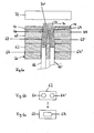
- FIG. 1 is a possible carrier element in the form of a bristle carrying plate 10 in a perspective view obliquely from above.
- a number of passages 16 extend. These have in the example shown a kidney-shaped or oval cross-section.
- the passages may also have a circular or any other cross section in the form of a closed contour.
- From the bottom 14 is in the direction towards below a ring-shaped Zentri mecanicswulst 18, which extends at a small distance from the side edge of the bristle carrier plate 10 along this and is preferably formed wedge-shaped tapering towards the free end.
- a circumferential and along the side edge extending welding edge 19 is attached. This serves in the process of connecting bristle carrier plate 10 and toothbrush body 28.
- the welding edge 19 can of course also be provided at any other location laterally or on the underside of the bristle carrier plate 10. In particular, it is also possible to attach the welding edge to the centering bead 18. Of course, these alternative arrangements of the welding edge necessitate adjustments to the counter-geometry of the bristle carrying plate 10, that is, to the recess 32.
- FIG. 2 shows in the same representation as FIG. 1 the bristle support plate 10, which is provided with a schematically indicated bristle facing 20.
- the bristle stocking 20 consists of bundles of bristles 22, that is, a bundle of bristles 22 per passage 16.
- Each of the bristle bundles 22 consists of a plurality of bristles; these are described in detail below.
- FIG. 3 shows a head portion 24 and a portion of an adjoining neck portion 26 of a toothbrush body 28.
- the neck portion 26 connects at the side facing away from the head portion 24 in a well-known manner, the handle portion.
- the head area 24 is of his in the FIG. 3 upper side 30 ago provided with a recess 32 which corresponds to the shape of the bristle carrying plate 10 and is limited by a bottom 34 substantially.
- the side wall of this recess 32 has a circumferential shoulder, which forms a welding shoulder 35.
- the back 36 of the toothbrush body 28 is located on the opposite side of the front 30 and is lying in the view shown below.
- FIG. 4 shows the bristle carrier plate 10 provided with the bristle stock 20 inserted into the recess 32. The insertion is facilitated by the Zentri mecanicswulst 18.
- the upper surface 12 of the bristle carrier plate 10 is aligned in the finished state of the toothbrush in a preferred manner with the front side 30 of the toothbrush body 28.
- the bristle carrier plate 10 is firmly connected to the toothbrush body 28, preferably by means of ultrasonic welding. In this case, a weld is performed in the region of the welding edge 19 and the welding paragraph 35.
- the bristle facing 20 projects beyond the top 12.
- FIG. 4 thus shows the head portion and a portion of the neck portion of a toothbrush 28. Of course, at this point, other methods for bristle or Brstentragplättchenverank für be used.
- the bristle support plate 10 is preferably made of a hard component, as described earlier.
- the head region 24 and the neck region 26 of the toothbrush body 28 are also made from one of these hard components.
- the same hard component is used for the bristle carrier plate 10 and the toothbrush body 28, at least in the contact area of the two parts.
- both the bristle carrier plate 10 and the toothbrush body 28 can be produced in a multi-component injection molding process.
- both the bristle carrier plate 10 and the toothbrush body 28 may each be composed of one or more hard components and / or of one or more soft components.
- An extract of possible hard and soft components is listed earlier in the text. If the bristle carrier plate 10 consists of one or more hard components and one or more soft components, the passages 16 are preferably arranged in the hard component.
- the soft component can be used both for the formation of additional soft-elastic cleaning elements on the bristle carrier plate 10 or on the head region 24 or attached to the toothbrush body 28 for functional or decorative purposes.
- FIG. 5 shows a longitudinal section along a central longitudinal plane, wherein this central longitudinal plane is perpendicular to the front side 30 of the head part 24.
- the central longitudinal plane or the sectional plane runs doing so by the five in FIG. 4
- the bristles are arranged in the longitudinal direction of the toothbrush centrally arranged bristle bundles 22.
- the bristles are not individually detailed, but shown schematically in bundles as area or volume.
- the reflowed end regions 70 form a readily discernable bristle feltsheet 21, which in the embodiment shown extends over virtually the entire underside 14 of the bristle carrier lamina 10.
- the bristle carrier plate 10 is connected via its welding edge 19 fixed to the welding shoulder 35 of the head part 24.
- the welding area is in the Fig. 5 shown schematically with a line as a delimitation. Adjacent to the head part 24 and fixedly connected thereto, the neck part 26 of the toothbrush body 28 is arranged.
- FIG. 6a shows a way to equip a bristle carrier plate 10 with a bristle bundle 22 having both pointed bristles 40 and cylindrical bristles 39.
- the die 62 has a receiving recess 64, in which pointed bristles 40 are inserted, and close to a further receiving recess 64 ', in which cylindrical bristles 39 are introduced or have become, on.
- the guide passages 69 and 69 'of the funnel plate 63 associated with these receiving recesses 64 and 64' converge toward each other in the direction of the bristle carrier plates 10 arranged on the funnel plate 63 so that they form a single common outlet for the bristles 40 and 39 at the downstream end.
- the two passages 69 and 69 ' still form separate outlets, but which lie directly next to each other.
- the outlet or the directly adjacent outlets are aligned
- the bundle 22 becomes sharpened and the bundle 22 of cylindrical bristles 40, 39 pass through the common passage of the bristle carrier plate 10 pushed through until their end portions 70, 70 'protrude beyond the bottom 14 of the bristle carrying plate 10.
- the bristles 40, 39 are fastened to the bristle carrier plate 10, forming a bristle melt carpet 21.
- the bristle carrier plate 10 provided with the bristle trim 20 is removed from the tool 60 and brought together with the toothbrush body 28 in a manner known from the prior art and fastened there.
- the bristles 40, 39 instead of through the bristle carrier plate 10 passed through into a mold cavity. Plastic is then injected into the mold cavity around the brush head form and anchor the bristles 40, 39 in this way.
- FIG. 6b shows a plan view of a section of the die 62 with the receiving recesses 64 and 64 '.
- the guide recesses 69 and 69 'associated receiving recesses 64 and 64' unite to the bristle carrier plate 10 facing side of the funnel plate 63 to a single common outlet 65 as in FIG. 6c shown. It is so that the sum of the cross-sectional areas of Fig. 6b , which together form a bundle of bristles 22 equal to the cross-sectional area of the common outlet 65.
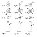
- the Figures 7a-c, 8a-c and 9a-c each show a possible manufactured bristle bundle 22 with bristles, which have a higher bristle end and thus form two different useable areas.
- the bristle bundles 22 shown are formed by bristles from a plurality of receiving recesses 64.
- the bristle bundles 22 or their higher-lying parts are each formed by a receiving recess 64 or a single profiled pin 66. That is, all bristles which originate from a receiving recess 64 have the same length in the final product.
- the Figures 7a, 8a and 9a the corresponding arrangement of the receiving recesses 64 of the die is shown. In FIG.
- FIG. 7b will be seen a plan view of the finished bristle bundle 22, wherein the part of the bristle bundle 22, the bristles having higher bristle ends has shown gray.
- the bundle of bristles has the shape of an equilateral triangle in its plan view, with the higher part of the bristle bundle 22 extending toward a tip of the triangle.
- FIG. 7c is a side view of the bristle bundle 22 FIG. 7b shown.
- FIG. 8b is a substantially circular bristle bundle 22 shown with a gray, centrally arranged higher standing bristle bundle part.
- the FIG. 8c shows a side view of the in FIG. 8b illustrated bristle bundle.
- FIG. 9b Another possible embodiment of a bristle bundle 22 is shown in FIG. 9b shown.
- the bristle bundle 22 has a square shape. In this case, three of the four of the bundles of bristles divided into quadrants have bristles with a higher bristle end.
- FIG. 9c shows a side view of the in FIG. 9b illustrated bristle bundle. In the Figs. 7a-c and 8a-c Bristle bundles 22 are shown in which the smaller proportion of the total cross-section is higher. In Fig. 9a-c the opposite situation is shown. The larger proportion of the cross section is higher and a smaller proportion is lower.
- Fig. 7a-c and Fig. 8a-c another detail is highlighted.
- the higher-standing parts of the bristle bundles 22 can be arranged both at the edge of the bristle bundle 22, as well as in the middle of lower-lying bristles surrounded in the bristle bundle 22nd
- FIG. 10a a further possible embodiment of a single bristle bundle 22 is shown, which is made of bristles which originate from only one receiving recess 64.
- the FIG. 10a shows the receiving recess 64 of the die. That in the FIG. 10b shown bristle bundles 22 has in plan view a circular shape with a gray, centrally arranged elevated bristle bundle part. The corresponding side view of the bristle bundle is in FIG. 10d displayed.
- FIG. 10c is a plan view of the bristle bundle corresponding profiled pin 66. As shown in FIG. 10e it can be seen, the profiled pin 66 has a recess 68 corresponding to the raised bundle part.
- the circular shape of the recess 68 has a diameter of 0.3 mm to 0.8 mm, preferably 0.5 mm.
- This embodiment shows the variant in which the higher bristle bundle part is completely surrounded by the lower bristle bundle part.
- FIGS. 11a-e a further possible embodiment of a single bristle bundle 22 is shown, which is made of bristles which originate from only one receiving recess 64.
- the FIG. 11a shows the receiving recess 64 of the die. That in the FIG. 11b shown bristle bundles 22 has in plan view again a circular shape with a gray, circular segment-shaped raised bristle bundle part. The raised bristle bundle part is bounded on the one hand by the circular arc of the circumference of the bristle bundle 22 and on the other hand by a secant.
- the corresponding side view of the bristle bundle is in FIG. 11d displayed.
- FIG. 11c is a plan view of the bristle bundle corresponding profiled pin 66. As shown in FIG.
- the profiled pin 66 has a recess 68 corresponding to the raised bundle part.
- This embodiment shows the variant in which the higher-lying bristle bundle part lies partly on the edge of the bristle bundle and on the other hand is surrounded by the lower-lying bristle bundle part.
- FIG. 12a shows the receiving recess 64 of the die. That in the FIG. 12b illustrated bristle bundles 22 has in plan view a circular shape with a raised bristle bundle part shown in gray. In contrast to the embodiments shown above, that in the FIGS. 12b and 12d in bristle bundles shown in plan view or side view not only one but two higher bristle bundle parts in the same bundle of bristles.
- the two higher-order bristle bundle parts like the bundle of bristles 22 themselves, have a circular shape and are arranged symmetrically on a diameter line of the bristle bundle.
- FIG. 12c is a plan view of the bristle bundle corresponding profiled pin 66 is shown. Like from the FIG. 12e it can be seen, the profiled pin 66 has two recesses 68 corresponding to the raised bundle part.
- the example is intended to show that in a bristle bundle 22 a plurality of elevated bristle bundle parts can be formed.
- the higher bristle bundle parts may have different bristle lengths within the same higher-standing bristle bundle part.
- the higher bristle bundle parts can have a total of different bristle lengths.
- FIGS. 13, 14 and 15 show further exemplary embodiments of profile pins 66, each with a different shaped recess 68.
- profile pin 66 according to FIG. 13 has a groove-shaped, along a diameter line of the circular profiled pin 66 extending recess 68, has the in figure 14 Profile pin shown a cross-shaped recess 68.
- the in FIG. 15 illustrated profiled pin 66 has a centrally disposed triangular recess 68.
- the Figures 16a-d show a further embodiment of a bristle bundle 22 with bristles, of which at least one part has a higher bristle end.
- the four receiving recesses 64 of the die 62 corresponding to the bristle bundle 22 are shown.
- profile pins 66 have two a centrally disposed recess 68.
- FIG. 16c shown top view of the finished bristle bundle 22 two gray areas shown on a diagonal of the square bristle bundle with higher standing bristle ends.
- the FIG. 16d shows the finished bristle bundle 22 in side view.
- the higher-standing parts of the bristle bundle 22 are achieved in this embodiment by a plurality of profiled pins 66. Depending on a recess in the profile pin 66 is assigned to a higher part.
- FIGS. 17a-d show a further embodiment of a bristle bundle 22 with bristles, of which at least one part has a higher bristle end.
- the three receiving recesses 64 of the die 62 corresponding to the bristle bundle 22 are shown.
- profile pins 66 all have one circular-sector-shaped in each case the other two profiled pins 66 facing recess 68.
- FIG. 17c shown top view of the finished bristle bundle 22 to see a gray-shaped, triangular region of the bristle bundle 22 with higher bristle ends.
- the triangular higher part of the bristle bundle 22 is arranged centrally in the likewise triangular bristle bundle 22.
- the FIG. 17d shows the finished bristle bundle 22 in side view.
- the higher part of the bristle bundle 22 is achieved in this embodiment by a plurality of profile pins 66.
- the circular sector-shaped indentations of the individual profile pins 66 each represent only one part, which as a whole ultimately forms the raised part of the bristle bundle 22.
- the Figures 18a-d represent a further embodiment of a bristle bundle 22 with bristles, of which at least one part has a higher bristle end.
- the four receiving recesses 64 of the die corresponding to the bristle bundle 22 are shown.
- profile pins 66 have two a groove-shaped extending through a diameter line recess 68, whereas the recesses of the other two profile pins 66 are each circular segment-shaped.
- top view of the finished bristle bundle 22 result in the recesses of the profile pins 66 complementary raised portions of the bristle bundle 22 a diagonally across the square bristle bundle 22 extending comb.
- the FIG. 18d shows the finished bristle bundle in side view.
- the higher-standing parts of the finished bristle bundle 22 are achieved in this embodiment by the combination of the recesses of a plurality of profile pins 66.
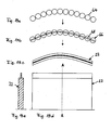
- FIG. 19a show a possible embodiment of an elongated bristle bundle 22.
- the receiving recesses 64 of the die 62 can be seen.
- the profile recesses 64 associated with the receiving recesses 64 are in the FIG. 19b shown.
- the profile pins 66 all have a straight, groove-shaped recess 68 which extends through the center of the respective profile pin 66.
- Both the receiving recesses and the corresponding profiled pins 66 are arranged along an arcuate line in such a way that the straight, groove-shaped recesses 68 of the individual profiled pins 66 form a continuous recess 68.
- the FIG. 19c shows a plan view of the corresponding, elongated bristle bundle 22.
- the elevated portion of the bristle bundle 22 is shown in turn gray.
- the combination of the straight, groove-shaped recesses 68 of the individual profile pins 66 in the finished bundle of bristles 22, a centrally disposed continuous higher part of the bristle bundle 22 is achieved in the form of a comb.
- the Figure 19d shows a side view of the finished bristle bundle 22 according to the FIG. 19c , In the Figure 19e is a cross section along the line AA in Figure 19d shown.
- One of the ways that can be used in connection with this embodiment is that although the profile pins 66 are provided with straight recesses 66 in the final product but a circular arc-shaped contour should be created. In the process, it is possible to make the transition continuous by the funnel plate 63 is designed accordingly. With her The transition from straight to round and continuous can be created easily.
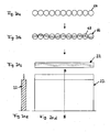
- FIG. 20a shows a further possible embodiment of an elongated bristle bundle 22.
- the receiving recesses 64 of the die 62 can be seen.
- the profile recesses 64 associated with the receiving recesses 64 are in the FIG. 20b shown.
- the profile pins 66 all have a groove-shaped recess 68, which does not necessarily pass through the center of the circular profile pin 66.
- Both the receiving recesses 64 and the corresponding profile pins 66 are arranged along a straight line.
- the groove-shaped recesses 68 are arranged such that a slightly meandering line is formed.
- the FIG. 20c shows a plan view of the corresponding, elongated bristle bundle 22.
- the elevated portion of the bristle bundle 22 is shown in turn gray.
- a continuous, higher-lying part of the bristle bundle 22 in the form of a meandering comb is achieved.
- the FIG. 20d shows a side view of the finished bristle bundle 22 according to the FIG. 20c , In the FIG. 20e is a cross section along the line BB in FIG. 20d shown. Good to see the higher in the form of a comb part of the bristle bundle 22nd
- the bristle length of the higher-standing part of the bristle bundle can vary. In this way, a height profile can be realized in the designed comb.
- the higher-order bristle bundle parts formed in this way preferably form a continuous, stepless contour. Next, it is also possible to make the contour interrupted or even unsteady.
- the arrangement of the profile pins 66 e.g. along a curved line, and on the other hand by the shape and arrangement of the recesses 68 in the individual profile pins 66 achieve a "composite" shape of the part raised in the finished bundle of bristles.
- bristle types can be used.
- cylindrical bristles 39 or pointed bristles 40 are used.
- Fig. 21a shows the bristle end of a cylindrical bristle.
- the cylindrical bristles are preferably made of polyamide (PA). They have over the bristle length a substantially constant nominal diameter ⁇ nenn (diameter at the thickest point of the bristle), which is for example 0.15 to 0.25 mm, on.
- the tip 22a of the bristle is rounded in the final state in the brush.
- the cross section of the cylindrical bristle is preferably circular. But there are also other cross-sectional shapes possible, for example, square, rectangular or diamond-shaped.
- Topped bristles 40 are in Fig. 21b outlined. Topped bristles 40 are preferably made of polyester (PBT) and also have a constant diameter over a range of their length, eg also a nominal diameter of 0.15-0.25 mm. Toward the tip 40a, the bristle 40 tapers, beginning at a distance a from the tip 40a. Measured from the top 40a corresponds to the diameter at the appropriate location, for example, the following values: Distance (mm) % of the nominal diameter Average tolerance 0.1 8th% 5-15% 1 25% 15-35% 2 45% 30-60% 3 60% 50-80% 4 75% 60-90% 5 80% 70-90% 6 85% > 75% 7 90% > 80%
- the tapering process is based on the reduction of the diameter by means of a chemical process. Depending on the length of the stay of the bristle in the chemical substance, the plastic degrades and reduces the diameter. The shape of the tip is so influenceable.
- the taper is dimensioned in both cases as stated above.
- the one-sided sharpened bristles have a taper at one end and at the other end they are cylindrically shaped and can be rounded off.
- the bristles, which are sharpened on both sides, are designed with a sharpening at both ends.
- the pointed bristles can be made the same as the cylindrical bristles.
- the nominal diameter is left over 75% over a major part of the length.
- the above table shows that the tapering of the filaments is predominantly on the last 4 to 5 mm. With this configuration, the tip 23a can optimally achieve the smallest fissures and the interdental spaces with sufficient filament stability.
- cylindrical or unilaterally tapered bristles are used.
- a length, starting from the brush head is selected between 7 mm and 13 mm.
- the bristles may be completely or partially colored. Accordingly, in the case of partially colored bristles, for example, only the bristle ends or only one bristle end or else all but the bristle ends can be colored.
- the coloration itself may be used as an indicator color, i.e. the color wears away in use and thus serves as a usage indicator or as a permanent coloration.
- the cylindrical bristles which are made of polyamide, for example, be colored with food colors and be provided on the paint with a paint.
- Possible food colors that can be used are, for example, blue "aluminum lake of 3,3'-dioxo-2,2'-diindolinyidenes-5,5'-disulfonic acid", for yellow " Aluminum Lake of 5-hydroxy-1- (4-sulfophenyl) -4- (4-sulfophenylazo) -3-pyrazolecarboxylic acid "or” aluminum lake of 6-hydroxy-5- (4-sulfophenylazo) -2-naphthalenesulfonic acid acid.
- Topped bristles which are made of polyester, can not be colored in this way.
- the coloring of these bristles requires a chemical process, which is not discussed here.
- the advantage of coloring may be that the technical aspect of different lengths of bristles can be made visible, for example, when only the higher standing bristle ends are colored, or when only the lower-lying bristle ends are colored.
- the use of the indication of use can be created by the design as an indicator game for the customer.
- the part of the bristles is colored, which comprises the higher-standing bristle ends.
- the coloring of the two-sided ends is still possible.
- the coloring has, if it concerns only the bristle tips, on the finished toothbrush a length of 2 mm to 10 mm, preferably between 3 mm and 8 mm. Due to the processing, the coloration on the unprocessed bristles is longer or adapted, since at most certain parts of the coloring are ground away or cut away. Accordingly, the coloration in the raw material need not be the same length at both ends of the bristles as it may vary in the final product. Preferably, the coloration in the final product is the same length at both bristle ends, if both bristle ends are colored.
- design variants shown in this document are exemplary and the individual forms and elements of these design variants can be combined with other design variants without departing from the scope of this invention.
Abstract
Description
Die vorliegende Erfindung betrifft eine Zahnbürste mit einer Borstenfeldgestaltung sowie ein Verfahren zu deren Herstellung.The present invention relates to a toothbrush having a bristle field design and to a method for the production thereof.
Zahnbürsten weisen üblicherweise einen Bürstenkopf mit einem aus Borstenbündeln gebildeten Borstenfeld auf. Derartige Zahnbürsten sind aus dem Stand der Technik bekannt. Die Borstenfelder der Zahnbürsten wurden mit der Zeit mannigfach gestaltet, um ihre Anwendung, das heisst, einerseits die Reinigungswirkung und andererseits die Handhabung für den Anwender zu verbessern. Eine dieser Entwicklungen betrifft die Verwendung von profilierten Borstenfeldern sowie von Borstenbündeln mit unterschiedlich hochstehenden Borsten.Toothbrushes usually have a brush head with a bristle field formed from bristle bundles. Such toothbrushes are known from the prior art. The bristle fields of the toothbrushes have been diversified over time to improve their application, that is, on the one hand the cleaning effect and on the other hand the handling for the user. One of these developments relates to the use of profiled bristle fields and bristle bundles with bristles of different heights.
US Design 425,306 zeigt ein ornamentales Borstenfeld mit im Wesentlichen dreiecksförmigen Borstenbündeln, an deren Ecken höherstehende Borsten angeordnet sind.US design 425,306 shows an ornamental bristle field with substantially triangular bristle bundles, at the corners of higher standing bristles are arranged.
Die der vorliegenden Erfindung zugrunde liegende Aufgabe ist die Bereitstellung einer einfach herstellbaren Zahnbürste, die eine sehr gute Reinigungswirkung entfaltet und in ihrer Handhabung einfach ist.The object underlying the present invention is to provide a toothbrush which is easy to produce and which has a very good cleaning effect and is easy to handle.
Die Aufgabe wird durch ein Verfahren mit den Merkmalen des Anspruchs 1 sowie eine Zahnbürste mit den Merkmalen des Anspruchs 7 sowie eine Vorrichtung mit den Merkmalen des Anspruchs 12 gelöst. Vorteilhafte Ausführungsformen sind Gegenstand der abhängigen Ansprüche.The object is achieved by a method having the features of claim 1 and a toothbrush having the features of claim 7 and a device having the features of
Beim erfindungsgemässe Verfahren zum Herstellen von ankerlos beborsteten Zahnbürsten, wird ein Borstenbündel mit zylindrischen Borsten und/oder zugespitzten Borsten in eine Aufnahmeausnehmung eines Werkzeugs einer Beborstungsmaschine eingeführt. Mittels eines in der Aufnahmeausnehmung geführten Profilstifts wird auf das dem Stift zugewandte Ende der Borsten des Borstenbündels zu deren Ausrichtung eingewirkt, so dass die Borsten des Borstenbündels mittels einer Stirnseite des Profilstifts ausgerichtet werden und dadurch die der Topographie der Stirnseite des Profilstifts komplementäre Topographie ausbilden, wobei der Profilstift auf der auf die Borsten einwirkenden Stirnfläche eine nicht stetige Oberfläche aufweist, welche mehrere Ebenen bildet. Nicht stetig heisst, dass die Oberfläche einen kantenförmige Übergang, d.h. eine Kante, aufweist.In the method according to the invention for producing anchorless brushed toothbrushes, a bristle bundle with cylindrical bristles and / or pointed bristles is introduced into a receiving recess of a tool of a bristling machine. By means of a guided in the receiving recess profile pin is acted on the pin facing the end of the bristles of the bristle bundle to their orientation, so that the bristles of the bristle bundle are aligned by means of an end face of the profiled pin and thereby the topography of the end face of the profiled pin complementary topography form, wherein the profiled pin has a non-continuous surface on the end face acting on the bristles, which forms a plurality of planes. Not continuous means that the surface has an edge-shaped transition, ie an edge.
Eine Vorrichtung zur Durchführung des erfindungsgemässen Verfahrens zur Herstellung einer Zahnbürste umfasst eine Matrize mit darin geführten Profilstiften, wobei die Profilstifte eine hochglanzpolierte oder geläppte Oberfläche aufweisen.An apparatus for carrying out the method according to the invention for producing a toothbrush comprises a die with profile pins guided therein, wherein the profile pins have a highly polished or lapped surface.
Eine erfindungsgemässe Zahnbürste wird aus Kunststoff hergestellt und umfasst mindestens eine Hartkomponente und/oder eine oder mehrere Weichkomponenten. Im Weiteren umfasst der aus einem Kopfteil, einem Griffteil und einen den Kopfteil und den Griffteil verbindenden Halsteil bestehende Grundkörper der Zahnbürste ein Trägerelement, bevorzugt in Form eines Trägerplättchens. Das aus Borstenbündeln gebildete Borstenfeld ist auf dem Trägerelement angeordnet. Sowohl der Kopf-, der Hals-, der Griffteil und auch das Trägerelement umfassen mindestens eine Hartkomponente und/oder mindestes eine Weichkomponente. Vorzugsweise sind der Kopfteil beziehungsweise die Schnittstelle zum Trägerelement und das Trägerelement selbst aus derselben Hartkomponente gefertigt. Als Hartkomponenten werden bevorzugt folgende Thermoplaste eingesetzt: Styrolpolymerisate, z.B. Styrolacrylnitril (SAN), Polystyrol (PS) Acrylnitrylbutadienstyrol (ABS), Styromethylmethacrylate (SMMA) und Styrolbutadien; Polyolefine wie Polypropylen (PP) oder Polyethylen (PE), sowohl in der Form von High Density Polyethylen (HDPE) als auch in der Form von Low Density Polyethylen (LDPE); Polyester, z.B. Polyethylenterephtalat (PET) in der Form von säuremodifiziertem Polyethylenterephtalat (PETA) oder in der Form von glykolmodifiziertem Polyethylenterephtalat (PETG), Polybutylenterephtalat (PBT), säuremodifiziertes Polycyclohexylenedimethyleneterephtalate (PCT-A) und glykolmodifiziertes Polycyclohexylenedimethylenetherephtalate (PCT-G); Cellulosederivate, z.B. Celluloseacetat (CA), Celluloseacetobutyrat (CAB), Cellulosepropionat (CP), Celluloseacetphtalat (CAP) und Cellulosbutyrat (CB); Polyamide (PA), z.B. PA6.6, PA6.10 und PA6.12; Polymethylmethacrylat (PMMA); Polycarbonat (PC); Polyoxymethylen (POM); Polyvinylchlorid (PVC) und Polyurethan (PUR). Besonders bevorzugt wird Polypropylen mit einem E-Modul im Bereich von 1000 N/mm2 bis 2400 N/mm2, ganz besonders bevorzugt im Bereich von 1300 N/mm2 bis 1800 N/mm2.A toothbrush according to the invention is made of plastic and comprises at least one hard component and / or one or more soft components. Furthermore, the main body of the toothbrush comprising a head part, a grip part and a neck part connecting the head part and the grip part comprises a carrier element, preferably in the form of a carrier plate. The bristle field formed from bristle bundles is arranged on the carrier element. Both the head, the neck, the handle part and also the carrier element comprise at least one hard component and / or at least one soft component. Preferably, the head part or the interface to the carrier element and the carrier element itself are made of the same hard component. The following thermoplastics are preferably used as hard components: styrene polymers, eg styrene acrylonitrile (SAN), polystyrene (PS) acrylonitrile butadiene styrene (ABS), styromethyl methacrylates (SMMA) and styrene butadiene; Polyolefins such as polypropylene (PP) or polyethylene (PE), both in the form of high density polyethylene (HDPE) and in the form of low density polyethylene (LDPE); Polyester, eg Polyethylene terephthalate (PET) in the form of acid modified polyethylene terephthalate (PETA) or in the form of glycol modified polyethylene terephthalate (PETG), polybutylene terephthalate (PBT), acid modified polycyclohexylenedimethylene terephthalate (PCT-A) and glycol modified polycyclohexylenedimethylene ether terephthalate (PCT-G); Cellulose derivatives, eg, cellulose acetate (CA), cellulose acetobutyrate (CAB), cellulose propionate (CP), cellulose acetate phthalate (CAP), and cellulose butyrate (CB); Polyamides (PA), eg PA6.6, PA6.10 and PA6.12; Polymethyl methacrylate (PMMA); Polycarbonate (PC); Polyoxymethylene (POM); Polyvinyl chloride (PVC) and polyurethane (PUR). Particularly preferred is polypropylene having an E-modulus in the range of 1000 N / mm 2 to 2400 N / mm 2 , most preferably in the range of 1300 N / mm 2 to 1800 N / mm 2 .
Als Weichkomponenten werden bevorzugt thermoplastische Elastomere (TPE) eingesetzt: thermoplastische Polyurethane (TPE-U); thermoplastische Styrol-Elastomere (TPE-S), z.B. Styrol-Ethylen-Butylen-Styrol-Copolymer (SEBS) oder Styrol-Butadien-Styrol-Copolymer (SBS); thermoplastische Polyamid-Elastomere (TPE-A); thermoplastische Polyolefin-Elastomere (TPE-O); thermoplastische Polyester-Elastomere (TPE-E). Daneben können die Thermoplaste Polyurethane (PUR) und Polyethylene (PE) auch als Weichkomponente eingesetzt werden. Bevorzugt wird ein TPE-S eingesetzt. Die Shore A Härte der eingesetzten Weichkomponenten ist bevorzugt kleiner als 90 Shore A.As soft components, thermoplastic elastomers (TPE) are preferably used: thermoplastic polyurethanes (TPE-U); thermoplastic styrene elastomers (TPE-S), e.g. Styrene-ethylene-butylene-styrene copolymer (SEBS) or styrene-butadiene-styrene copolymer (SBS); thermoplastic polyamide elastomers (TPE-A); thermoplastic polyolefin elastomers (TPE-O); thermoplastic polyester elastomers (TPE-E). In addition, the thermoplastics polyurethanes (PUR) and polyethylenes (PE) can also be used as a soft component. Preferably, a TPE-S is used. The Shore A hardness of the soft components used is preferably less than 90 Shore A.
Die eingesetzten Hart- und Weichkomponenten werden bevorzugt im Zwei- oder Mehrkomponentenspritzgussverfahren verarbeitet. Dabei bildet sich zwischen den Komponenten ein Material- oder Formschluss.The hard and soft components used are preferably in two- or multi-component injection molding processed. This forms a material or positive connection between the components.
Der Ausdruck Borsten bezeichnet die einzelnen Filamente, aus denen Borstenbündel aufgebaut sind. Die Ausdrücke Borste, Borstenfilament oder Filament werden synonym verwendet und bezeichnen alle die oben erwähnten, einzelnen Filamente eines Borstenbündels. Borsten können aus verschiedenen Materialien bestehen. Eingesetzt werden beispielsweise Polyamide (PA) oder Polyester (PBT). Ein Beispiel für ein eingesetztes Polyamid ist PA6.12. Dabei finden Polyamide bevorzugt für zylindrische Borsten Verwendung, während Polyester vorzugsweise für einseitig oder beidseitig zugespitzte Borsten verwendet werden. Die Borsten können unterschiedliche Durchmesser aufweisen. In der Regel weisen Borsten eine zylindrische Form auf. Bevorzugt ist der Querschnitt wenigstens annähernd kreiszylinderförmig und über die Länge der Borste konstant, auf diese Weise wird ein Kreiszylinder gebildet. Weitere Querschnittsformen sind möglich, beispielsweise quadratische, rechteckige oder rautenförmige. Zugespitzte Borsten weisen zum einen einen zylindrischen Teil auf, in welchem sie einen konstant bleibenden Querschnitt haben, zum anderen verjüngen sich diese Borsten über einen gewissen Bereich auf mindestens ein Nutz-Ende zu. Bei einseitig zugespitzten Borsten, wie sie vorliegend in erfindungsgemässen Zahnbürsten eingesetzt werden können, weist der an den zugespitzten Bereich anschliessende und so dem freien Ende gegenüberliegende Bereich der zugespitzten Borsten einen zylindrischen Querschnitt auf. Im Weiteren können Borsten verschiedene Arten von Enden aufweisen. Das Borstenende von zylindrischen Borsten ist in der Regel einerseits wenigstens annähernd halbkugelförmig, während andererseits das Borstenende von zugespitzten Borsten zu einer Spitze ausläuft. Die Borstenenden von zylindrischen Borsten werden in der Regel bearbeitet, um allfällige scharfe Kanten am Borstenende zu vermeiden, die zum Beispiel vom Schneiden herrühren können. Bearbeiten heisst, dass die Enden der zylindrischen Borsten, zum Beispiel nachdem sie auf eine Länge für die Weiterverarbeitung geschnitten wurden, gerundet werden. Dadurch werden scharfe Kanten der Borstenenden der zylindrischen Borsten gebrochen und ein wenigstens annähernd halbkugelförmiges Borstenende erzielt.The term bristles refers to the individual filaments of which bundles of bristles are made up. The terms bristle, bristle filament or filament are used synonymously and all refer to the above-mentioned individual filaments of a bristle bundle. Bristles can be made of different materials. For example, polyamides (PA) or polyesters (PBT) are used. An example of a polyamide used is PA6.12. In this case, polyamides are preferably used for cylindrical bristles, while polyesters are preferably used for one-sided or double-sided sharpened bristles. The bristles can have different diameters. As a rule, bristles have a cylindrical shape. Preferably, the cross section is at least approximately circular cylindrical and constant over the length of the bristle, in this way a circular cylinder is formed. Other cross-sectional shapes are possible, for example, square, rectangular or diamond-shaped. Tapered bristles have on the one hand a cylindrical part in which they have a constant cross-section, on the other hand, these bristles taper over a certain range to at least one payload end. In one-sided sharpened bristles, as they can be used in tooth brushes according to the invention, the area of the sharpened bristles which adjoins the pointed area and thus faces the free end has a cylindrical cross-section. Furthermore, bristles may have different types of ends. The bristle end of cylindrical bristles is usually on the one hand at least approximately hemispherical, while on the other hand, the bristle end of pointed bristles leaking to a point. The bristle ends of cylindrical bristles are usually machined to avoid any sharp edges at the bristle end, which may for example result from cutting. Machining means that the ends of the cylindrical bristles are rounded, for example, after being cut to a length for further processing. This breaks sharp edges of the bristle ends of the cylindrical bristles and achieves an at least approximately hemispherical bristle end.
Die Borsten können zumindest teilweise eingefärbt sein. Aus Polyester (PBT) bestehende Borsten werden auf chemischem Wege eingefärbt. Bestehen die Borsten aus Polyamid (PA), können auch Lebensmittelfarben zur Einfärbung verwendet werden. Beispielsweise wird Aluminum Lake of 3,3'-dioxo-2,2'-diindolinydene-5,5'-disulfonic arid für eine Blaufärbung, Aluminium lake of 5-hydroxy-1-(4-sulfophenyl)-4-(4-sulfophenylazo)-3-pyrazolecarboxylic acid für eine gelbe Färbung oder Alumnium lake of 6-hydroxy-5-(4-sulfophenylazo)-2-naphtalene-sulfonic acid ebenfalls für eine gelbe Färbung eingesetzt. Ganz oder teilweise eingefärbte Borsten müssen lackiert werden, um ihre maschinelle Weiterverarbeitbarkeit zu gewährleisten. Beispielsweise um die Reibung zwischen den Borsten und den Maschinenteilen zu verringern.The bristles may be at least partially colored. Polyester (PBT) bristles are dyed chemically. If the bristles are made of polyamide (PA), food colors can also be used for coloring. For example, Aluminum Lake of 3,3'-dioxo-2,2'-diindolinydene-5,5'-disulfonic acid for a blue color, aluminum lake of 5-hydroxy-1- (4-sulfophenyl) -4- (4- sulfophenylazo) -3-pyrazolecarboxylic acid for yellow staining or aluminum lake of 6-hydroxy-5- (4-sulfophenylazo) -2-naphthalenesulfonic acid also used for yellow staining. Wholly or partially colored bristles must be painted in order to ensure their machinability. For example, to reduce the friction between the bristles and the machine parts.
Erfindungsgemässe Borstenbündel umfassen Borsten mit mindestens zwei unterschiedlichen Längen. Das heisst, die freien Enden der Borsten stehen unterschiedlich weit von der borstentragenden Oberseite des Kopfteils hoch und bilden im Falle von Borstenbündeln mit Borsten von zwei unterschiedlichen Längen zwei verschiedene Nutzflächen. Der Abschnitt des Borstenbündels, der im Querschnitt sämtliche Borsten enthält, wird als Borstenbündelstamm bezeichnet. Der Abschnitt des Borstenbündels, welcher im Querschnitt lediglich die Borsten mit höherstehenden Borstenenden umfasst, wird als reduzierter Teil des Borstenbündels bezeichnet. Die oben genannten zwei Nutzflächen werden einerseits durch die Borstenenden der Borsten mit kürzerer Länge und andererseits durch die Borstenenden der Borsten mit grösserer Länge, das heisst, mit den höherstehenden Borstenenden, gebildet.Boron bundles according to the invention comprise bristles with at least two different lengths. That is, the free ends of the bristles are at different heights from the bristle-carrying top of the head and up in the case of bristle bundles with bristles of two different lengths two different areas. The portion of the bundle of bristles which contains all the bristles in cross-section is called the bundle of bristles. The portion of the bundle of bristles, which in cross-section only comprises the bristles with the bristle ends projecting upwards, is referred to as a reduced part of the bristle bundle. The above-mentioned two effective surfaces are formed on the one hand by the bristle ends of the bristles of shorter length and on the other hand by the bristle ends of the bristles of greater length, that is, with the higher bristle ends.
Der Borstenbündelstamm weist bevorzugt eine Höhe von 6 mm bis 11 mm, besonderes bevorzugt von 8 mm bis 10 mm, auf. Die Höhe des reduzierten Teils des Borstenbündels beträgt bevorzugt 9 mm bis 15 mm, besonders bevorzugt 10 mm bis 12 mm. Die Höhe wird dabei jeweils von der Oberseite des Kopfteils oder des Trägerelements gemessen, eigentlich ab dem Austrittspunkt der Borste aus der Oberfläche. Der Abstand der Endfläche des Borstenbündelstamms zur Endfläche des reduzierten Teils beträgt zwischen 0.5 mm und 5 mm vorzugsweise zwischen 2 mm und 3 mm. Wie oben beschrieben umfassen Borstenbündel Borsten mit unterschiedlich weit hochstehenden Borstenenden, die zwei Nutzflächen bilden. Die Borsten können zudem unterschiedliche Borstenenden aufweisen. Zum einen können die Borstenenden abgerundet sein, wie dies für zylindrische Borsten beschrieben wurde, zum anderen können Borsten sich zu ihrem freien Ende hin verjüngenden Bereich aufweisen, der ein zugespitztes Borstenende aufweist. In einer Ausführungsform weisen alle Borsten zugespitzte Borstenenden auf. In einer bevorzugten Variante weisen nur Borsten mit einem höherstehenden Borstenende ein zugespitztes Borstenende auf. Das heisst, nur der reduzierte Teil eines Borstenbündels weist Borsten mit zugespitztem Borstenende auf. Die übrigen Borsten dieses Borstenbündels mit tieferstehendem Borstenende sind zylindrische Borsten mit einem abgerundeten Borstenende. Damit wird die höherstehende Nutzfläche von Borsten mit zugespitztem Borstenenden gebildet, wogegen die tiefer liegende Nutzfläche von Borsten mit abgerundetem Borstenende gebildet wird. In einer weiteren Ausführungsform verhält es sich gerade umgekehrt. Die Borsten mit höherstehendem Borstenende weisen abgerundete Borstenenden auf. Dagegen weisen in dieser Ausführungsform die übrigen Borsten mit tieferstehendem Borstenende zugespitzte Borstenenden auf. Konsequenterweise wird in dieser Ausführungsform die höherstehenden Nutzfläche durch freie, abgerundete Borstenenden gebildet und die tieferstehende Nutzfläche durch freie, zugespitzte Borstenenden gebildet.The bristle bundle trunk preferably has a height of 6 mm to 11 mm, particularly preferably 8 mm to 10 mm. The height of the reduced portion of the bristle bundle is preferably 9 mm to 15 mm, particularly preferably 10 mm to 12 mm. The height is measured in each case from the top of the head part or the support element, actually from the exit point of the bristle from the surface. The distance of the end surface of the bristle bundle trunk to the end surface of the reduced part is preferably between 0.5 mm and 5 mm, between 2 mm and 3 mm. As described above, bristle bundles comprise bristles with bristle ends of different height which form two usable surfaces. The bristles can also have different bristle ends. On the one hand, the bristle ends may be rounded, as has been described for cylindrical bristles, on the other hand, bristles may have a tapering region towards their free end, which has a sharpened bristle end. In one embodiment, all bristles have pointed bristle ends. In a preferred variant, only bristles with a higher bristle end have a sharpened bristle end. This means that only the reduced part of a bundle of bristles has bristles sharpened bristle end. The remaining bristles of this bristle bundle with a lower bristle end are cylindrical bristles with a rounded bristle end. Thus, the higher usable area is formed by bristles with pointed bristle ends, whereas the lower lying useful area is formed by bristles with a rounded bristle end. In another embodiment, it is the other way around. The bristles with higher bristle ends have rounded bristle ends. In contrast, in this embodiment, the remaining bristles with a lower bristle end have pointed bristle ends. Consequently, in this embodiment, the higher usable space is formed by free, rounded bristle ends and the lower effective area is formed by free, pointed bristle ends.
Sowohl zylindrische Borsten mit abgerundetem Borstenende als auch Borsten mit zugespitztem Borstenende können ganz oder bevorzugt auch nur teilweise eingefärbt sein. Der eingefärbte Bereich einer Borste erstreckt sich über eine Länge von 2 mm bis 10 mm, vorzugsweise von 3 mm bis 8 mm. Ebenfalls bevorzugt werden lediglich Borsten mit höherstehendem Borstenende eingefärbt. Zudem erstreckt sich der eingefärbte Teil der Borsten im Falle von lediglich teilweise eingefärbten Borsten bevorzugt zu deren freien Borstenenden hin. Als alternative Ausführungsform weisen nur Borsten mit tieferstehendem Borstenende einen eingefärbten Bereich auf, wobei dieser Bereich sich vorzugsweise zu den freien Borstenenden hin erstreckt.Both cylindrical bristles with a rounded bristle end and bristles with a sharpened bristle end may wholly or preferably only be partially colored. The colored area of a bristle extends over a length of 2 mm to 10 mm, preferably 3 mm to 8 mm. Also preferably only bristles are colored with higher standing bristle end. In addition, in the case of only partially colored bristles, the colored part of the bristles preferably extends toward the free bristle ends thereof. As an alternative embodiment, only bristles having a lower bristle end have a colored area, which area preferably extends toward the free bristle ends.
Die zumindest teilweise Einfärbung der Borsten kann neben Design- und ästhetischen Aspekten auch andere Vorteile mit sich bringen. Eine Ausgestaltung der Einfärbung beziehungsweise des Farbe selbst bringt mit sich, dass das Ausbleichen des eingefärbten Bereichs einer Borste beziehungsweise das Auswaschen der Farbe bei fortschreitender Benutzungsdauer durch den Anwender als effizienter Indikator für die kürzer werdende Lebensdauer einer erfindungsgemässen Zahnbürste eingesetzt werden. Dadurch erhält der Anwender eine vorteilhafte Verbrauchsanzeige.The at least partial coloring of the bristles may have other advantages in addition to design and aesthetic aspects to bring oneself. An embodiment of the coloring or of the color itself entails that the fading of the colored area of a bristle or the washing out of the color as the use period progresses are used by the user as an efficient indicator of the shorter life of a toothbrush according to the invention. This gives the user an advantageous consumption display.
Das Borstenfeld wird durch die auf dem Trägerelement angeordneten Borstenbündel gebildet. Die Borstenbündel können dabei in einem Raster auf dem Trägerelement angeordnet sein. Das Borstenfeld kann durch eine oder vorzugsweise zwei oder mehr verschiedene Arten von Borstenbündeln gebildet sein. Neben Borstenbündeln mit Borsten, die mindestens zwei unterschiedlich weit hochstehende Borstenenden aufweisen, können auch Borstenbündel mit zylindrischen Borsten oder Borstenbündel mit Borsten, die ein zugespitztes freies Ende aufweisen, oder auch Borstenbündel die aus einer Kombination von zylindrischen und zugespitzten Borsten bestehen, vorhanden sein. Im Borstenfeld können die Borstenbündel mit Borsten unterschiedlich weit hochstehender Borstenenden ausschliesslich in den äussersten Bereichen angeordnet sein, während sich im Inneren des Borstenfeldes Borstenbündel befinden, welche nach dem bekannten Stand der Technik geformt sind. Beispielsweise können im Innern des Borstenfeldes zylindrische Borsten mit einer Höhe von Borstenenden angebracht sein, welche in ihrer Borstenlänge auch kürzer ausgestaltet sein können als die Borstenbündel mit Borsten, die mindestens zwei unterschiedlich weit hochstehende Borstenenden aufweisen. Möglich sind ebenfalls abwechselnde Längs- oder Querbereiche aus den oben genannten verschiedenen Arten von Borstenbündeln. Die Borstenbündel können generell, das heisst auch die Borstenbündel mit Borsten, die mindestens zwei unterschiedlich weit hochstehende Borstenenden aufweisen, in den verschiedensten Querschnitten ausgestaltet sein. Beispiele dafür sind kreisförmige, annähernd kreisförmige, gebogenene, eckige oder freiförmige Strukturen.The bristle field is formed by the bristle bundles arranged on the carrier element. The bristle bundles can be arranged in a grid on the support element. The bristle field may be formed by one or preferably two or more different types of bristle bundles. In addition to bristle bundles with bristles which have at least two bristle ends of different heights, bristle bundles with cylindrical bristles or bristle bundles with bristles having a pointed free end or also bristle bundles consisting of a combination of cylindrical and sharpened bristles may be present. In the bristle field, the bristle bundles with bristles of bristles of different heights can be arranged exclusively in the outermost regions, while in the interior of the bristle field bristle bundles are formed, which are shaped according to the known state of the art. For example, in the interior of the bristle field cylindrical bristles with a height of bristle ends may be attached, which may be configured shorter in their bristle length than the bristle bundles with bristles having at least two bristle ends of different height. Also possible are alternating longitudinal or transverse areas of the above different types of bristle bundles. The bristle bundles can generally, that is also the bristle bundles with bristles, which have at least two bristle ends of different heights upstanding, be configured in a variety of cross-sections. Examples of these are circular, approximately circular, curved, angular or free-form structures.
Die Borstenbündel und auch die höherstehenden Borstenenden im Borstenbündel sind vorzugsweise im Wesentlichen senkrecht angeordnet. Eine Schrägstellung gegenüber der Trägerplatte kann aber auch realisiert werden. Dabei ragen die höherstehenden Enden in einem Winkel gegenüber der Trägerplatte aus dem Borstenbündel. Die Orientierung der Schrägstellung ist dabei nicht eingeschränkt, die Borsten die von der Schrägstellung betroffen sind, können in der Projektion senkrecht auf die Trägerplatte gegenüber der Längsachse der Zahnbürste einen beliebigen Winkel einnehmen. Borstenbündel mit schräggestellten Borsten können im selben Borstenfeld mit senkrecht stehenden Borstenbündeln kombiniert werden.The bristle bundles and also the higher bristle ends in the bundle of bristles are preferably arranged substantially vertically. An inclination relative to the carrier plate can also be realized. The higher ends protrude at an angle relative to the support plate from the bristle bundle. The orientation of the inclination is not limited, the bristles that are affected by the skew can take any angle in the projection perpendicular to the support plate relative to the longitudinal axis of the toothbrush. Bristle bundles with inclined bristles can be combined in the same bristle field with vertical bristle bundles.
Weiter können in einem Borstenfeld die Längen der tieferstehenden Borstenenden und auch die Längen der höherstehenden Borstenenden variiert werden. In einem Borstenfeld ist es demzufolge möglich mit der einen Länge oder der anderen Länge oder mit beiden Längen zu variieren.Further, in a bristle field, the lengths of the lower-lying bristle ends and also the lengths of the higher bristle ends can be varied. In a bristle field, it is therefore possible to vary with one length or the other length or with both lengths.
Im Weiteren können die erfindungsgemässen Borstenbündel mit zusätzlichen, auf dem Trägerelement oder direkt am Kopfteil angeordneten weichelastischen Strukturen kombiniert sein, wobei die weichelastischen Strukturen aus mindestens einer der oben beschriebenen Weichkomponenten bestehen. Solche weichelastischen Strukturen sind vorzugsweise als weichelastische Reinigungs- oder Massageelemente ausgestaltet. Die weichelastischen Reinigungs- oder Massageelemente können aufgrund der grossen Gestaltungsfreiheit sehr verschiedenartige Formen aufweisen. Nachfolgend einige Beispiele von möglichen Ausgestaltungsvarianten. Neben einer schaberartigen Ausgestaltung können die Reinigungs- oder Massageelemente auch als über Eck angeordnete flügelartige oder stiftförmige ausgestaltete Reinigungs- oder Massageelemente vorhanden sein. Möglich sind auch schaberartige in ihrer Draufsicht wellenförmig gestaltete Reinigungs- oder Massageelemente oder gebogene, allenfalls annähernd kreisförmig gebogene Reinigung- oder Massageelemente. Die annähernd kreisförmigen Reinigungs-oder Massageelemente können einen geschlossenen Kreis bilden oder in Segmenten in einem Kreis angeordnet sein. Die weichelastischen Reinigungs- oder Massageelemente ergänzen die Reinigungswirkung der Borsten, indem sie die Entfernung von Zahnbelägen und das Polieren der Zahnoberfläche verstärken beziehungsweise bewirken. Zudem dienen weichelastische Strukturen, insbesondere die weichelastischen Reinigungs- oder Massageelemente, auch der Dämpfung von Putzbewegungen und nicht zuletzt der Massage des Zahnfleischs. Analog wie die verschiedenen Arten von Borstenbündeln miteinander kombiniert beziehungsweise angeordnet werden können, gestattet das ankerlose Beborsten der Zahnbürste mittels des Trägerelements eine sehr grosse Gestaltungsfreiheit in der Anordnung weichelastischen Strukturen, insbesondere der Reinigungs- oder Massageelemente. Zum Beispiel können schaberartige, in ihrer Draufsicht gebogene und auf einem Kreis angeordnete weichelastische Reinigungs- oder Massageelemente eines oder mehrere Borstenbündel umschliessen, wobei die weichelastischen Reinigungselemente ihrerseits von Borstenbündeln umgeben sind oder sein können. Zudem erlaubt das AFT-Verfahren die Realisierung von Borstenbündeln mit einem beispielsweise bogenförmigen Querschnitt, da kein Anker notwendig ist der die Breite des Borstenbündels begrenzt.Furthermore, the bristle bundles according to the invention can be combined with additional soft-elastic structures arranged on the carrier element or directly on the head part, wherein the soft-elastic structures consist of at least one of the soft components described above consist. Such soft elastic structures are preferably designed as soft-elastic cleaning or massage elements. The soft-elastic cleaning or massage elements can have very different shapes due to the great freedom of design. Below are some examples of possible design variants. In addition to a scraper-like configuration, the cleaning or massage elements can also be present as corner-mounted wing-like or pin-shaped configured cleaning or massage elements. Also possible are scraper-like in their plan view wavy designed cleaning or massage elements or curved, possibly approximately circular curved cleaning or massage elements. The approximately circular cleaning or massage elements may form a closed circle or be arranged in segments in a circle. The soft-elastic cleaning or massage elements complement the cleaning effect of the bristles by enhancing the removal of dental plaque and the polishing of the tooth surface or effect. In addition, soft-elastic structures, in particular the soft-elastic cleaning or massage elements, also serve to dampen cleaning movements and not least the massage of the gums. Analogous to how the different types of bundles of bristles can be combined or arranged with each other, the anchorless bursting of the toothbrush by means of the support element allows a very great design freedom in the arrangement of flexible structures, in particular the cleaning or massage elements. For example, scraper-like, curved in plan view and arranged on a circle soft elastic cleaning or Massage elements enclose one or more bristle bundles, the soft elastic cleaning elements are in turn surrounded by bristle bundles or can be. In addition, the AFT method allows the realization of bristle bundles with an example arcuate cross-section, since no anchor is necessary which limits the width of the bristle bundle.
Erfindungsgemässe Borstenbündel umfassen Borsten mit mindestens zwei unterschiedlichen Längen. Die Borsten mit den höherstehenden Borstenenden bilden dabei eine (zweite) Nutzfläche. Diese Nutzfläche kann eine im Wesentlichen parallel zur Oberseite des Kopfteils verlaufende Ebene sein. Die Nutzfläche kann jedoch auch eine in Bezug auf die Oberseite des Kopfteils geneigte Ebene sein oder die Nutzfläche kann ein, z.B. wellenförmiges, dachförmig oder gezacktes Profil aufweisen.Boron bundles according to the invention comprise bristles with at least two different lengths. The bristles with the higher bristle ends form a (second) effective area. This useful surface may be a plane extending substantially parallel to the top of the head part. However, the effective area may also be a plane inclined with respect to the top of the head or the effective area may be a, e.g. have wave-shaped, roof-shaped or serrated profile.
Der borstentragende Kopfteil kann ein Borstenfeld aufweisen, das aus verschiedenen Arten von Borstenbündeln gebildet wird. Neben den Borstenbündeln mit Borsten, die unterschiedlich weit hochstehende Borstenenden aufweisen und damit mindestens zwei Nutzebenen bilden, können auch weitere Borstenbündel mit zylindrischen Borsten oder mit ausschliesslich zugespitzten Borsten vorhanden sein. Zusätzlich können auch weichelastische Strukturen, z.B. in der Form weichelastischer Reinigungs- und Massageelemente, vorhanden sein. Die weichelastischen Strukturen können direkt am Kopfteil oder an einem Trägerelement, das in den Kopfteil eingesetzt und mit diesem verbunden wird, angeformt sein.The bristle-carrying head portion may comprise a bristle field formed of different types of bristle bundles. In addition to the bristle bundles with bristles which have bristle ends of different heights and thus form at least two levels of use, it is also possible for there to be further bristle bundles with cylindrical bristles or with exclusively sharpened bristles. In addition, soft-elastic structures, e.g. in the form of soft-elastic cleaning and massage elements, be present. The soft-elastic structures can be formed directly on the head part or on a carrier element which is inserted into the head part and connected to it.
Beim AFT-Verfahren (Anchor Free Tufting) werden die Borsten beziehungsweise die Borstenbündel ohne Hilfe eines Ankers am Kopfteil oder an einem Trägerelement, z.B. einem Borstentragplättchen, befestigt. Im Falle eines Trägerelements werden dabei die Borsten bündelweise mit ihrem dem freien Nutzende gegenüberliegenden stumpfen Ende durch Durchlässe im Trägerelement hindurchgeführt, so dass ein Endbereich der Borstenbündel über die Unterseite des Trägerelements hinausragt. An diesem über die Unterseite des Trägerelements hinausragenden Endbereich der Borsten werden diese durch Aufschmelzen, Verkleben oder Verschweissen befestigt.In the Anchor Free Tufting (AFT) process, the bristles or bundles of bristles become unaided Ankers on the head part or on a support element, such as a bristle support plate attached. In the case of a carrier element, the bristles are thereby guided in bundles with their blunt end opposite the free use end through passages in the carrier element, so that an end region of the bristle bundles protrudes beyond the underside of the carrier element. At this over the underside of the support member projecting end portion of the bristles they are fixed by melting, gluing or welding.
Im erfindungsgemässen Verfahren wird ein Werkzeug, das aus einer einem blockartigen Grundkörper, auch Matrize genannt, und einer Trichterplatte besteht in einer Beborstungsmaschine verwendet. Durch die Matrize des Werkzeugs hindurch verläuft in vertikaler Richtung, eine Aufnahmeausnehmung. Der Querschnitt dieser Aufnahmeausnehmung ist über die gesamte Länge der geradlinigen Aufnahmeausnehmung in der Matrize konstant. In der Aufnahmeausnehmung ist ein Stift, ein sogenannter Profilstift, in Gleitpassung geführt.In the method according to the invention, a tool which consists of a block-like main body, also referred to as a die, and a funnel plate is used in a bristling machine. Through the die of the tool passes in the vertical direction, a receiving recess. The cross section of this receiving recess is constant over the entire length of the rectilinear receiving recess in the die. In the receiving recess is a pin, a so-called profile pin, guided in sliding fit.
Die Profilstifte müssen in dem Bereich, in welchem sie mit Borsten in Kontakt kommen, das heisst, an ihrer Stirnseite eine kratzerfreie polierte, bevorzugt eine geläppte Oberfläche oder hochglanzpolierte aufweisen. Je nach Form der Stirnseite des Profilstifts vorhandene Ausnehmungen müssen scharfe und gratfreie Kanten aufweisen, da sonst die Gefahr besteht, dass sich die Borstenfilamente beim Einführen in die Bohrung oder in der nachfolgenden Weiterverarbeitung verkeilen oder verklemmen. Zudem ist es vorteilhaft, wenn der Durchmesser am Borstenende, welches am Profilstift anliegt nicht kleiner ist als der Toleranzbereich zwischen dem Profilstift und der Aufnahmeausnehmung. Der Durchmesser der Vertiefung im Profilstift bringt mit sich, dass zwischen 3 und 8 Borsten das entsprechende Profil einnehmen. D.h. die angegebene Anzahl Borsten steht im Borstenbündel höher als der Rest. Im finalen Borstenbündel stehen auf diese Weise zwischen 5% und 25% vorzugsweise zwischen 10% und 15% der Borstenenden höher als der Rest. Die höherstehenden Borstenenden sind vorzugsweise zentrisch im Borstenbündel angeordnet, die Anordnung am Rand der Kontur des Borstenbündels ist eine weitere Möglichkeit der Anordnung. Die Tiefe der Vertiefung beträgt zwischen 0.5 mm und 5 mm vorzugsweise zwischen 2 mm und 3 mm. Im Verfahrensablauf wird die Matrize beziehungsweise deren Aufnahmeausnehmungen mit den zugehörigen Stiften von einem Kreisbogen der Beborstungsmaschine her mit Bündeln von zylindrischen oder zugespitzten Borsten gefüllt. Wobei der Kreisbogen der Matrize beziehungsweise der Aufnahmeausnehmung pro Durchgang 20 bis 50, vorzugsweise 35 bis 45 Borsten zuführt. Ein fertiges Borstenbündel kann sowohl Borsten aus lediglich einem Durchgang als auch aus mehreren Durchgängen des Kreisbogens umfassen. Im Weiteren besteht die Möglichkeit des Einsatzes eines variablen Kreisbogens. Dadurch kann die Anzahl der pro Durchgang zugeführten Borsten angepasst werden. Auf diese Weise kann ausgehend von einer Ausgangsborstenmenge (100%) eine Variabilität von +/- 34% erreicht werden. Dementsprechend können in einer Matrize verschieden grosse Aufnahmeausnehmungen angeordnet sein, welche auf der Zahnbürste zu verschieden grossen Borstenbündeln führt. Nach dem Füllen wird in einer weiteren Station der Beborstungsmaschine die Trichterplatte auf die Matrize gesetzt.In the region in which they come into contact with bristles, that is to say the profiled pins have on their front side a scratch-free polished, preferably a lapped surface or highly polished. Depending on the shape of the end face of the profiled pin existing recesses must have sharp and burr-free edges, otherwise there is a risk that the bristle filaments when inserting into the hole or in subsequent processing or jam. In addition, it is advantageous if the diameter at the bristle end, which rests on the profile pin is not smaller than the tolerance range between the profile pin and the Receiving recess. The diameter of the depression in the profile pin implies that between 3 and 8 bristles occupy the corresponding profile. That is to say the stated number of bristles is higher in the bundle of bristles than in the rest. In the final bristle bundle, between 5% and 25%, preferably between 10% and 15%, of the bristle ends are higher than the remainder. The bristle ends standing higher are preferably arranged centrically in the bristle bundle. the arrangement at the edge of the contour of the bristle bundle is another possibility of the arrangement. The depth of the recess is between 0.5 mm and 5 mm, preferably between 2 mm and 3 mm. In the course of the process, the die or its receiving recesses are filled with the associated pins by a circular arc of the bristle machine with bundles of cylindrical or pointed bristles. Wherein the arc of the die or the receiving recess per
Die Gleitpassung zwischen der Matrize und den Profilstiften ist derart ausgestaltet, dass die Spitzen der zugespitzten Borsten einen grösseren Durchmesser aufweisen als der Toleranzbereich der Gleitpassung. Die Bewegung der Profilstifte ist derart eingeschränkt, dass sie nur innerhalb der Matrize beweglich sind.The sliding fit between the die and the profiled pins is designed such that the tips of the sharpened bristles have a larger diameter than the tolerance range of the sliding fit. The movement of the profile pins is limited so that they are movable only within the die.
An seiner oben liegenden, in der Matrize befindenden Stirnseite, an welcher die Spitzen der Borsten anliegen, ist der Profilstift beispielsweise mit einer sacklochartigen Vertiefung versehen, um dem betreffenden Borstenbündel, in der Endform, eine Topographie zu vermitteln, bei welcher ein Teil der Borsten ein höherstehendes Borstenende aufweist. Die Endform der Borstenbündel wird durch die Form der Stirnseite des Profilstifts entscheidend beeinflusst. Anstelle einer sacklochartigen Vertiefung sind jedoch auch andere beliebige Topographien der Stirnseite des Profilstiftes möglich.At its top, located in the die end, on which abut the tips of the bristles, the profiled pin is provided, for example with a blind hole-like depression to the respective bristle bundle, in the final form, to provide a topography in which a part of the bristles a has higher bristle end. The final shape of the bundles of bristles is decisively influenced by the shape of the face of the profile pin. Instead of a blind hole-like depression, however, other arbitrary topographies of the end face of the profile pin are possible.
Anschliessend wird die Trichterplatte auf die Matrize und darauf, falls dies im Verfahren vorgesehen ist, ein Borstentragplättchen derart abgelegt, dass der diesem Borstenbündel zugeordnete Durchlass des Borstentragplättchens mit dem entsprechenden Führungsdurchlass in der Trichterplatte fluchtet. Dabei kommt die Oberseite des Borstentragplättchens auf der Trichterplatte zur Anlage, so dass die Unterseite des Borstentragplättchens nach oben frei liegt. Der Vollständigkeit halber sei erwähnt, dass dieser Führungsdurchlass der Trichterplatte andererseits auch mit der Aufnahmeausnehmung korrespondiert. Durch Bewegung des Profilstifts in Richtung nach oben auf das Borstentragplättchen zu werden die Borsten nach aufwärts bewegt und mit ihrem stumpfen Ende voraus durch die Trichterplatte und den Durchlass hindurch gestossen, bis ein an das stumpfe Ende anschliessender Endbereich im zylinderförmigen Abschnitts zylindrischer oder zugespitzter Borsten über die Unterseite des Borstentragplättchens vorsteht. Anschliessend wird ein Heizstempel auf die Borsten oder in deren Nähe abgesenkt, so dass der Endbereich der Borsten schmilzt und auf der Unterseite einen, die Unterseite mindestens teilweise bedeckenden Borstenschmelzteppich 21 bildet und dadurch die Borsten untereinander und am Borstentragplättchen befestigt.Subsequently, the funnel plate is placed on the die and thereon, if this is provided in the method, a bristle carrier plate such that the bristle carrier plate associated with this bristle bundle is aligned with the corresponding guide passage in the funnel plate. The upper side of the bristle carrying plate comes to rest on the funnel plate, so that the underside of the bristle carrying plate is exposed upwards. For the sake of completeness it should be mentioned that this guide passage of the funnel plate on the other hand also corresponds to the receiving recess. By moving the profiled pin in an upward direction on the bristle support plate to the bristles to upward moved and pushed with its blunt end through the funnel plate and the passage therethrough until an adjoining the blunt end portion in the cylindrical portion of cylindrical or pointed bristles over the underside of the bristle carrier plate protrudes. Subsequently, a heating stamp is lowered onto the bristles or in the vicinity thereof so that the end region of the bristles melts and forms on the underside a
In analoger Weise wie oben dargestellt, kann die Matrize des Werkzeugs eine weitere Aufnahmeausnehmung mit darin geführten Profilstiften aufweisen. In diese werden wiederum Borsten, z.B. zylindrische Borsten eingeführt; diese kommen mit ihren allenfalls vorgängig mechanisch bearbeiteten Enden an der Stirnseite der weiteren Profilstifte zur Anlage. Dabei wird je nach der Form der Stirnseite der Profilstifte wiederum eine Topographie, das heisst, ein Borstenfeld mit unterschiedlich hochstehenden Borstenenden, erzeugt.In an analogous manner as shown above, the die of the tool can have a further receiving recess with profile pins guided therein. In turn, bristles, e.g. cylindrical bristles introduced; These come with their possibly previously mechanically machined ends on the front side of the other profile pins to the plant. In this case, depending on the shape of the front side of the profile pins in turn a topography, that is, a bristle field with different upstanding bristle ends generated.
Gleichzeitig mit dem oben beschriebenen Profilstift werden die weiteren Profilstifte verschoben, um die jeweiligen Borstenbündel durch die weiteren Durchlässe des Borstentragplättchens hindurch zu stossen, bis die Borstenbündel mit einem Endabschnitt über die Unterseite des Borstentragplättchens vorstehen. Das Schmelzen der Endabschnitte erfolgt wie oben beschrieben.Simultaneously with the profile pin described above, the further profile pins are displaced to push the respective bristle bundles through the further passages of the bristle carrying plate until the bristle bundles protrude with an end portion over the underside of the bristle carrying plate. The melting of the end sections takes place as described above.
Werden verschiedene Kunststoffe für die Herstellung der zylindrischen oder zugespitzten Borsten verwendet, entsteht ein Borstenschmelzteppich 21 aus den entsprechenden Kunststoffen. Insbesondere kann dieser Borstenschmelzteppich 21 aus Polyester (zugespitzte Borsten) und Polyamid (zylindrische Borste) bestehen. Da sich diese beiden Kunststoffarten in der Borstenschmelze nicht verbinden, ist bevorzugt darauf zu achten, dass mit den einzelnen Materialien Gruppen von Borstenbündeln gebildet werden, bei welchen sich die Borstenschmelze innerhalb einer Gruppe verbinden kann. Die gleichartigen Borstenbündel werden diesbezüglich vorzugsweise in Gruppen mit unmittelbarer Nähe platziert. In diesem Fall werden somit vorzugsweise die Borstenbündel aus zugespitzten Borsten beziehungsweise zylindrischen Borsten in Aufnahmeausnehmungen beziehungsweise weitere Aufnahmeausnehmungen eingeführt, welche benachbart angeordnet sind und eine Gruppe bilden.Are different plastics used for the production of cylindrical or pointed bristles, creates a
Die vorliegende Erfindung kann für Borstenfelder unterschiedlicher Erzeugnisse verwendet werden. Zum Beispiel können manuelle Zahnbürsten, elektrische Zahnbürsten mit rotierender, oszillierender, schwenkender oder translatorischer Bewegung (als Seitwärts- oder Längsbewegung, vibrierender Bewegung oder einer Kombination aus diesen Bewegungen können mit Borstenbündeln ausgestattet werden, die Borsten mit mindestens zwei unterschiedlich hochstehende Borstenenden aufweisen.The present invention can be used for bristle fields of different products. For example, manual toothbrushes, electric toothbrushes with rotating, oscillating, pivoting or translational motion (as sideways or longitudinal movement, vibratory motion or a combination of these movements may be provided with bristle bundles having bristles with at least two bristle ends of different heights.
Die Erfindung wird nun anhand von in den Figuren dargestellten Ausführungsbeispielen näher beschrieben. Es zeigen rein schematisch:
- Fig. 1
- in perspektivischer Sicht ein Trägerelement in der Form eines Borstentragplättchens;
- Fig. 2
- ebenfalls in perspektivischer Ansicht das Borstentragplättchen mit einem Borstenfeld;
- Fig. 3
- ebenfalls in perspektivischer Ansicht einen Kopfbereich und einen Teil eines Halsbereichs eines Zahnbürstenkörpers mit einer Ausnehmung im Kopfbereich;
- Fig. 4
- in perspektivischer Ansicht den Zahnbürstenkörper aus
Figur 3 mit die Ausnehmung eingesetztem borstentragenden Borstentragplättchen ausFigur 2 ; - Fig. 5
- den vollständig montierten Bürstenkopf aus
Figur 4 im Längsschnitt; - Fig. 6a
- einen Schnitt durch ein Werkzeug mit einer Aufnahmeausnehmung für die zugespitzten Borsten und einer weiteren Aufnahmeausnehmung für zylindrische Borsten, einem in der Aufnahmeausnehmung geführten Stift und einem in der weiteren Aufnahmeausnehmung geführten weiteren Stift für das Bewegen und Ausrichten der Borsten, einem auf der Trichterplatte angeordneten Borstentragplättchen, wobei die Trichterplatte die zugespitzten und zylindrischen Borsten zu einem gemeinsamen Durchlass des Borstentragplättchens leitet, und einem Heizstempel;
- Fig. 6b
- eine Draufsicht auf die Matrize aus
Figur 6a ; - Fig. 6c
- eine Draufsicht auf die Trichterplatte aus
Figur 6a ; - Fig. 7a
- eine Draufsicht auf die Aufnahmeausnehmungen für Borsten in einer Matrize;
- Fig. 7b
- eine Draufsicht auf das fertige Borstenbündel gefertigt mit einer Matrize gemäss
Figur 7a ; - Fig. 7c
- eine Seitenansicht des fertigen Borstenbündels aus
Figur 7b ; - Fig. 8a
- eine Draufsicht auf die Aufnahmeausnehmungen für Borsten in einer weiteren Matrize;
- Fig. 8b
- eine Draufsicht auf das fertige Borstenbündel gefertigt mit einer Matrize gemäss
Figur 8a ; - Fig. 8c
- eine Seitenansicht des fertigen Borstenbündels aus
Figur 8b ; - Fig. 9a
- eine Draufsicht auf die Aufnahmeausnehmungen für Borsten in einer weiteren Matrize;
- Fig. 9b
- eine Draufsicht auf das fertige Borstenbündel gefertigt mit einer Matrize gemäss
Figur 9a ; - Fig. 9c
- eine Seitenansicht des fertigen Borstenbündels aus
Figur 9b ; - Fig. 10a
- eine Draufsicht auf eine Aufnahmeausnehmung für Borsten in einer Matrize;
- Fig. 10b
- eine Draufsicht auf das fertige Borstenbündel gemäss
Figur 10a ; - Fig. 10c
- eine Draufsicht auf den entsprechenden Profilstift für das fertigen eines Borstenbündels gemäss
Figur 10b ; - Fig. 10d
- eine Seitenansicht auf das Borstenbündel gefertigt gemäss
Figur 10a bis 10c ; - Fig. 10e
- eine Seitenansicht des Profilstifts aus
Figur 10c ; - Fig. 11a
- eine Draufsicht auf eine Aufnahmeausnehmung für Borsten in einer Matrize;
- Fig. 11b
- eine Draufsicht auf das fertige Borstenbündel gemäss
Figur 11a ; - Fig. 11c
- eine Draufsicht auf den entsprechenden Profilstift für das fertigen eines Borstenbündels gemäss
Figur 11b ; - Fig. 11d
- eine Seitenansicht auf das Borstenbündel gefertigt gemäss
Figur 11a bis 11c ; - Fig. 11e
- eine Seitenansicht des Profilstifts aus
Figur 11c ; - Fig. 12a
- eine Draufsicht auf eine Aufnahmeausnehmung für Borsten in einer Matrize;
- Fig. 12b
- eine Draufsicht auf das fertige Borstenbündel;
- Fig. 12c
- eine Draufsicht auf den entsprechenden Profilstift für das fertigen eines Borstenbündels gemäss
Fig. 12b ; - Fig. 12d
- eine Seitenansicht auf das Borstenbündel gefertigt gemäss
Figur 12 a bis c ; - Fig. 12e
- eine Seitenansicht des Profilstifts aus
Figur 11c ; - Fig. 13
- eine Draufsicht auf einen weiteren möglichen Profilstift;
- Fig. 14
- eine Draufsicht auf einen weiteren möglichen Profilstift;
- Fig. 15
- eine Draufsicht auf einen weiteren möglichen Profilstift;
- Fig. 16a
- eine Draufsicht auf die Aufnahmeausnehmungen einer Matrize;
- Fig. 16b
- eine Draufsicht auf die den Aufnahmausnehmungen gemäss
Figur 16a zugeordneten Profilstiften; - Fig. 16c
- eine Draufsicht auf das mittels den Profilstiften gemäss
Figur 16b erzeugte, fertige Borstenbündel; - Fig. 16d
- eine Seitenansicht auf das mittels den Profilstiften gemäss
Figur 16b erzeugte, fertige Borstenbündel; - Fig. 17a
- eine Draufsicht auf die Aufnahmeausnehmungen einer Matrize;
- Fig. 17b
- eine Draufsicht auf die den Aufnahmausnehmungen gemäss
Figur 17a zugeordneten Profilstiften; - Fig. 17c
- eine Draufsicht auf das mittels den Profilstiften gemäss
Figur 17b erzeugte, fertige Borstenbündel; - Fig. 17d
- eine Seitenansicht auf das mittels den Profilstiften gemäss
Figur 17b erzeugte, fertige Borstenbündel; - Fig. 18a
- eine Draufsicht auf die Aufnahmeausnehmungen einer Matrize;
- Fig. 18b
- eine Draufsicht auf die den Aufnahmausnehmungen gemäss
Figur 18a zugeordneten Profilstiften; - Fig. 18c
- eine Draufsicht auf das mittels den Profilstiften gemäss
Figur 18b erzeugte, fertige Borstenbündel; - Fig. 18d
- eine Seitenansicht auf das mittels den Profilstiften gemäss
Figur 16b erzeugte, fertige Borstenbündel; - Fig. 19a
- eine Draufsicht auf die Aufnahmeausnehmungen einer Matrize;
- Fig. 19b
- eine Draufsicht auf die den Aufnahmausnehmungen gemäss
Figur 19a zugeordneten Profilstiften; - Fig. 19c
- eine Draufsicht auf das mittels den Profilstiften gemäss
Figur 19b erzeugte, fertige Borstenbündel; - Fig. 19d
- eine Seitenansicht auf das mittels den Profilstiften gemäss
Figur 19b erzeugte, fertige Borstenbündel; - Fig. 19e
- ein Querschnitt durch das Borstenbündel gemäss
Figur 19d entlang der Linie A-A; - Fig. 20a
- eine Draufsicht auf die Aufnahmeausnehmungen einer Matrize;
- Fig. 20b
- eine Draufsicht auf die den Aufnahmausnehmungen gemäss
Figur 20a zugeordneten Profilstiften; - Fig. 20c
- eine Draufsicht auf das mittels den Profilstiften gemäss
Figur 20b erzeugte, fertige Borstenbündel; - Fig. 20d
- eine Seitenansicht auf das mittels den Profilstiften gemäss
Figur 20b erzeugte, fertige Borstenbündel; - Fig. 20e
- ein Querschnitt durch das Borstenbündel gemäss
Figur 20d entlang der Linie B-B; - Fig. 21a
- die Form des Endbereichs einer zylindrischen abgerundeten Borste; und
- Fig. 21b
- die Form des Endbereichs einer zugespitzten Borste.
- Fig. 1
- in perspective view, a carrier element in the form of a bristle carrying plate;
- Fig. 2
- likewise in perspective view, the bristle carrying plate with a bristle field;
- Fig. 3
- also in perspective view a head portion and a portion of a neck portion of a toothbrush body with a recess in the head area;
- Fig. 4
- in a perspective view of the toothbrush body
FIG. 3 with the recess inserted bristle-bearing bristle tinsel fromFIG. 2 ; - Fig. 5
- the fully assembled brush head
FIG. 4 in longitudinal section; - Fig. 6a
- a section through a tool having a receiving recess for the sharpened bristles and a further receiving recess for cylindrical bristles, a guided in the receiving recess pin and a guided in the other receiving recess further pin for moving and aligning the bristles, arranged on the funnel plate bristle carrying tabs, the funnel plate directing the tapered and cylindrical bristles to a common passage of the bristle carrier plate, and a heating punch;
- Fig. 6b
- a plan view of the die
FIG. 6a ; - Fig. 6c
- a plan view of the funnel plate
FIG. 6a ; - Fig. 7a
- a plan view of the receiving recesses for bristles in a die;
- Fig. 7b
- a plan view of the finished bristle bundle made with a die according to
Figure 7a ; - Fig. 7c
- a side view of the finished bristle bundle
FIG. 7b ; - Fig. 8a
- a plan view of the receiving recesses for bristles in another die;
- Fig. 8b
- a plan view of the finished bristle bundle made with a die according to
FIG. 8a ; - Fig. 8c
- a side view of the finished bristle bundle
FIG. 8b ; - Fig. 9a
- a plan view of the receiving recesses for bristles in another die;
- Fig. 9b
- a plan view of the finished bristle bundle made with a die according to
FIG. 9a ; - Fig. 9c
- a side view of the finished bristle bundle
FIG. 9b ; - Fig. 10a
- a plan view of a receiving recess for bristles in a die;
- Fig. 10b
- a plan view of the finished bristle bundle according to
FIG. 10a ; - Fig. 10c
- a plan view of the corresponding profile pin for the finished of a bristle bundle according to
FIG. 10b ; - Fig. 10d
- a side view of the bristle bundle according to
FIGS. 10a to 10c ; - Fig. 10e
- a side view of the profile pin
FIG. 10c ; - Fig. 11a
- a plan view of a receiving recess for bristles in a die;
- Fig. 11b
- a plan view of the finished bristle bundle according to
FIG. 11a ; - Fig. 11c
- a plan view of the corresponding profile pin for the finished of a bristle bundle according to
FIG. 11b ; - Fig. 11d
- a side view of the bristle bundle according to
FIGS. 11a to 11c ; - Fig. 11e
- a side view of the profile pin
FIG. 11c ; - Fig. 12a
- a plan view of a receiving recess for bristles in a die;
- Fig. 12b
- a plan view of the finished bristle bundle;
- Fig. 12c
- a plan view of the corresponding profile pin for the finished of a bristle bundle according to
Fig. 12b ; - Fig. 12d
- a side view of the bristle bundle according to
Figure 12 a to c ; - Fig. 12e
- a side view of the profile pin
FIG. 11c ; - Fig. 13
- a plan view of another possible profile pin;
- Fig. 14
- a plan view of another possible profile pin;
- Fig. 15
- a plan view of another possible profile pin;
- Fig. 16a
- a plan view of the receiving recesses of a die;
- Fig. 16b
- a plan view of the receiving recesses according to
FIG. 16a associated profile pins; - Fig. 16c
- a plan view of the means of the profile pins according to
FIG. 16b produced, finished bristle bundles; - Fig. 16d
- a side view of the means of the profile pins according
FIG. 16b produced, finished bristle bundles; - Fig. 17a
- a plan view of the receiving recesses of a die;
- Fig. 17b
- a plan view of the receiving recesses according to
Figure 17a associated profile pins; - Fig. 17c
- a plan view of the means of the profile pins according to
FIG. 17b produced, finished bristle bundles; - Fig. 17d
- a side view of the means of the profile pins according
FIG. 17b produced, finished bristle bundles; - Fig. 18a
- a plan view of the receiving recesses of a die;
- Fig. 18b
- a plan view of the receiving recesses according to
FIG. 18a associated profile pins; - Fig. 18c
- a plan view of the means of the profile pins according to
FIG. 18b produced, finished bristle bundles; - Fig. 18d
- a side view of the means of the profile pins according
FIG. 16b produced, finished bristle bundles; - Fig. 19a
- a plan view of the receiving recesses of a die;
- Fig. 19b
- a plan view of the receiving recesses according to
FIG. 19a associated profile pins; - Fig. 19c
- a plan view of the means of the profile pins according to
FIG. 19b produced, finished bristle bundles; - Fig. 19d
- a side view of the means of the profile pins according
FIG. 19b produced, finished bristle bundles; - Fig. 19e
- a cross section through the bristle bundle according to
Figure 19d along the line AA; - Fig. 20a
- a plan view of the receiving recesses of a die;
- Fig. 20b
- a plan view of the receiving recesses according to
FIG. 20a associated profile pins; - Fig. 20c
- a plan view of the means of the profile pins according to
FIG. 20b produced, finished bristle bundles; - Fig. 20d
- a side view of the means of the profile pins according
FIG. 20b produced, finished bristle bundles; - Fig. 20e
- a cross section through the bristle bundle according to
FIG. 20d along the line BB; - Fig. 21a
- the shape of the end portion of a cylindrical rounded bristle; and
- Fig. 21b
- the shape of the end portion of a sharpened bristle.
In
Das Borstentragplättchen 10 ist vorzugsweise aus einer Hartkomponente gefertigt, wie sie weiter vorne bereits beschrieben ist.The
Im gezeigten Beispiel ist auch der Kopfbereich 24 und der Halsbereich 26 des Zahnbürstenkörpers 28 aus einer dieser Hartkomponenten gefertigt. In bevorzugter Weise wird für das Borstentragplättchen 10 und den Zahnbürstenkörper 28 dieselbe Hartkomponente, wenigstens im Kontaktbereich der beiden Teile, verwendet.In the example shown, the
Der Vollständigkeit halber sei hier jedoch erwähnt, dass sowohl das Borstentragplättchen 10 als auch der Zahnbürstenkörper 28 im Mehrkomponenten-Spritzgiessverfahren hergestellt sein können. Dabei können sowohl das Borstentragplättchen 10 als auch der Zahnbürstenkörper 28 jeweils aus einer oder mehreren Hartkomponenten und / oder aus einer oder mehreren Weichkomponenten aufgebaut sein. Ein Auszug möglicher Hart- und Weichkomponenten ist weiter vorne in der Schrift aufgeführt. Besteht das Borstentragplättchen 10 aus einer oder mehreren Hartkomponenten und einer oder mehreren Weichkomponenten, sind die Durchlässe 16 vorzugsweise in der Hartkomponente angeordnet. Die Weichkomponente kann sowohl für die Ausformung von zusätzlichen weichelastischen Reinigungselementen am Borstentragplättchen 10 oder am Kopfbereich 24 genutzt werden oder am Zahnbürstenkörper 28 für funktionelle oder dekorative Zwecke angebracht werden.However, for the sake of completeness, it should be mentioned here that both the
Die
Auf entsprechende Art und Weise ist es möglich, mehrere einzelne Bündel 22 von Borsten 39, 40 aus verschiedenen Aufnahmeausnehmungen 64 mittels der Trichterplatte 63 zu vereinen und somit zusammen ein Borstenbüschel in einem gemeinsamen Durchlass 16 zu bilden. Auf dieselbe Art und Weise, wie in
Das mit dem Borstenbesatz 20 versehene Borstentragplättchen 10 wird dem Werkzeug 60 entnommen und mit dem Zahnbürstenkörper 28 nach aus dem Stand der Technik bekannter Art und Weise zusammengebracht und dort befestigt.The
In Beborstungsverfahren ohne Borstentragplättchen 10 werden, wie bereits beschrieben, die Borsten 40, 39 anstatt durch das Borstentragplättchen 10 hindurch in einen Formhohlraum geführt. In diesen Formhohlraum wird anschließend Kunststoff eingespritzt um den Bürstenkopf zu formen und die Borsten 40, 39 auf diese Weise zu verankern.In bristles without bristle
Die
Die
In
In den
In den
In den
Das Beispiel soll zeigen, dass in einem Borstenbündel 22 mehrere erhöhte Borstenbündelteile geformt sein können. Dabei ist eine Variante nicht gezeigt, die höherstehenden Borstenbündelteile können einerseits innerhalb desselben höherstehenden Borstenbündelteils unterschiedliche Borstenlängen haben. Andererseits können selbstverständlich auch die höherstehenden Borstenbündelteile insgesamt verschiedene Borstenlängen haben.The example is intended to show that in a bristle bundle 22 a plurality of elevated bristle bundle parts can be formed. In this case, a variant is not shown, the higher bristle bundle parts may have different bristle lengths within the same higher-standing bristle bundle part. On the other hand, of course, the higher bristle bundle parts can have a total of different bristle lengths.
Die
Die
Die
Die
Die
Die
Im Zusammenhang der in den
Die auf diese Weise gebildeten höherstehenden Borstenbündelteile bilden vorzugsweise eine stetige, stufenlose Kontur. Weiter ist es aber auch möglich, die Kontur unterbrochen oder eben unstetig zu gestalten.The higher-order bristle bundle parts formed in this way preferably form a continuous, stepless contour. Next, it is also possible to make the contour interrupted or even unsteady.
Durch das Kombinieren von Vertiefungen 68 in einzelnen Profilstiften 66 lässt sich einerseits durch die Anordnung der Profilstifte 66, z.B. entlang einer gebogenen Linie, und andererseits durch die Form und Anordnung der Vertiefungen 68 in den einzelnen Profilstiften 66 eine "zusammengesetzte" Form des im fertigen Borstenbündel erhöhten Teils erzielen.By combining
Für die Realisierung von erfindungsgemässen und erfindungsgemäss hergestellten Zahnbürsten können die verschiedensten Borstenarten verwendet werden. Bevorzugt werden zylindrische Borsten 39 oder zugespitzte Borsten 40 eingesetzt.For the realization of toothbrushes produced according to the invention and produced according to the invention, a wide variety of bristle types can be used. Preferably, cylindrical bristles 39 or pointed
Zugespitzte Borsten 40 sind in
Der Zuspitzungsprozess basiert auf der Reduktion des Durchmessers mittels einem chemischen Prozess. Je nach Länge des Aufenthaltes der Borste in der chemischen Substanz baut sich der Kunststoff ab und verringert sich der Durchmesser. Die Form der Spitze ist so beeinflussbar.The tapering process is based on the reduction of the diameter by means of a chemical process. Depending on the length of the stay of the bristle in the chemical substance, the plastic degrades and reduces the diameter. The shape of the tip is so influenceable.
Grundsätzlich existieren zwei Arten von zugespitzten Borsten. Jene die nur an einem Ende eine Zuspitzung aufweisen und jene die an beiden Borstenenden eine Zuspitzung haben. Die Zuspitzung ist von den Dimensionen her in beiden Fällen wie oben angegeben gestaltet. Die einseitig zugespitzten Borsten haben an einem Ende eine Zuspitzung und am anderen Ende sind sie zylindrisch gestaltet und können abgerundet werden. Die beidseitig zugespitzten Borsten sind an beiden Enden mit einer Zuspitzung ausgestaltet.There are basically two types of pointed bristles. Those who only have one point of sharpening at one end and those who have a point at both ends of the bristle. The taper is dimensioned in both cases as stated above. The one-sided sharpened bristles have a taper at one end and at the other end they are cylindrically shaped and can be rounded off. The bristles, which are sharpened on both sides, are designed with a sharpening at both ends.
Vom Querschnitt her können die zugespitzten Borsten gleich gestaltet werden wie die zylindrischen Borsten.From the cross section, the pointed bristles can be made the same as the cylindrical bristles.
Um genügend Stabilität der einzelnen Filamente zu bewahren, wird der Nenndurchmesser über einen Grossteil der Länge auf über 75% belassen. Die oben aufgeführte Tabelle zeigt, dass die Zuspitzung der Filamente zum überwiegenden Teil auf den letzten 4 bis 5 mm erfolgt. Mit dieser Ausgestaltung kann die Spitze 23a kleinste Fissuren und die Interdentalräume bei genügender Filamentstabilität optimal erreichen.In order to maintain sufficient stability of the individual filaments, the nominal diameter is left over 75% over a major part of the length. The above table shows that the tapering of the filaments is predominantly on the last 4 to 5 mm. With this configuration, the tip 23a can optimally achieve the smallest fissures and the interdental spaces with sufficient filament stability.
Für die vorliegende Erfindung werden vorzugsweise zylindrische oder einseitig zugespitzte Borsten verwendet.For the present invention preferably cylindrical or unilaterally tapered bristles are used.
Für alle Borstenarten wird, um eine genügende Flexibilität der Filamente zu erreichen eine Länge, ab Austritt aus dem Bürstenkopf, zwischen 7 mm und 13 mm gewählt.For all types of bristles, in order to achieve sufficient flexibility of the filaments, a length, starting from the brush head, is selected between 7 mm and 13 mm.
In der vorliegenden Erfindung sowie für Zahnbürsten generell können die Borsten komplett oder teilweise eingefärbt sein. Dementsprechend können bei teilweise eingefärbten Borsten beispielsweise nur die Borstenenden oder nur ein Borstenenden oder auch alles ausser die Borstenenden eingefärbt sein. Die Einfärbung selbst kann als Indikator-Einfärbung, d.h., die Farbe nutzt sich im Gebrauch ab und dient so als Gebrauchsindikator oder auch als permanente Einfärbung gestaltet sein.In the present invention, as well as for toothbrushes in general, the bristles may be completely or partially colored. Accordingly, in the case of partially colored bristles, for example, only the bristle ends or only one bristle end or else all but the bristle ends can be colored. The coloration itself may be used as an indicator color, i.e. the color wears away in use and thus serves as a usage indicator or as a permanent coloration.
Die zylindrischen Borsten, welche aus Polyamid hergestellt sind, können beispielsweise mit Lebensmittelfarben eingefärbt sein und über der Farbe mit einem Lack versehen sein. Mögliche, einsetzbare Lebensmittelfarben sind beispielsweise für blau "Aluminium Lake of 3,3'-dioxo-2,2'-diindolinyidene-5,5'-disulfonic acid", für gelb " Aluminium Lake of 5-hydroxy-1-(4-sulfophenyl)-4-(4-sulfophenylazo)-3-pyrazolecarboxylic acid" oder "Aluminium Lake of 6-hydroxy-5-(4-sulfophenylazo)-2-naphthalene-sulfonic acid". Diese Farben sind so ausgelegt, dass sie Food-Contact tauglich sind. Sind die Farben auf Borsten aufgebracht, so ist die Oberfläche meistens nicht mehr in der Qualität, die eine automatische Verarbeitung auf Zahnbürsten-Beborstungsmaschinen zulässt. Deshalb werden die gesamten Borsten oder wenigstens die eingefärbten Partien der Borsten mit einem Lack versehen. Dieser Lack macht die Oberfläche glatter und ermöglicht so die automatische Verarbeitung.The cylindrical bristles, which are made of polyamide, for example, be colored with food colors and be provided on the paint with a paint. Possible food colors that can be used are, for example, blue "aluminum lake of 3,3'-dioxo-2,2'-diindolinyidenes-5,5'-disulfonic acid", for yellow " Aluminum Lake of 5-hydroxy-1- (4-sulfophenyl) -4- (4-sulfophenylazo) -3-pyrazolecarboxylic acid "or" aluminum lake of 6-hydroxy-5- (4-sulfophenylazo) -2-naphthalenesulfonic acid acid. "These colors are designed to be suitable for Food-Contact, and when the colors are applied to bristles, the surface is usually no longer of the quality that allows for automatic processing on toothbrush bristles or at least the colored areas of the bristles are provided with a varnish which makes the surface smoother and thus allows automatic processing.
Zugespitzte Borsten, welche aus Polyester hergestellt sind, lassen sich auf diese Weise nicht einfärben. Die Einfärbung dieser Borsten verlangt nach einem chemischen Prozess, auf welchen an dieser Stelle aber nicht eingegangen wird.Topped bristles, which are made of polyester, can not be colored in this way. The coloring of these bristles requires a chemical process, which is not discussed here.
Der Vorteil einer Einfärbung kann sein, dass der technische Aspekt der verschieden langen Borsten sichtbar gemacht werden kann, beispielsweise wenn nur die höherstehenden Borstenenden eingefärbt sind, oder wenn lediglich die tieferstehenden Borstenenden eingefärbt sind. Weiter kann durch die Gestaltung als Indikator-Partie für den Kunden der Nutzen der Gebrauchsindikation (Verbrauchsindikation) geschaffen werden.The advantage of coloring may be that the technical aspect of different lengths of bristles can be made visible, for example, when only the higher standing bristle ends are colored, or when only the lower-lying bristle ends are colored. Furthermore, the use of the indication of use (consumption indication) can be created by the design as an indicator game for the customer.
Bevorzugt wird der Teil der Borsten eingefärbt, welcher die höherstehenden Borstenenden umfasst. Die Einfärbung der beidseitigen Enden ist dennoch möglich.Preferably, the part of the bristles is colored, which comprises the higher-standing bristle ends. The coloring of the two-sided ends is still possible.
Die Einfärbung hat, wenn sie nur die Borstenspitzen betrifft, auf der fertigen Zahnbürste eine Länge von 2 mm bis 10 mm vorzugsweise zwischen 3 mm und 8 mm. Aufgrund der Verarbeitung ist die Einfärbung auf den nicht verarbeiteten Borsten länger bzw. angepasst, da allenfalls gewisse Teile der Einfärbung weggeschliffen oder weggeschnitten werden. Dementsprechend muss die Einfärbung im Rohmaterial nicht an beiden Enden der Borsten gleich lang sein, wie sie auch im Endprodukt variieren kann. Vorzugsweise ist die Einfärbung im Endprodukt dennoch an beiden Borstenenden gleich lang, falls beide Borstenenden eingefärbt sind.The coloring has, if it concerns only the bristle tips, on the finished toothbrush a length of 2 mm to 10 mm, preferably between 3 mm and 8 mm. Due to the processing, the coloration on the unprocessed bristles is longer or adapted, since at most certain parts of the coloring are ground away or cut away. Accordingly, the coloration in the raw material need not be the same length at both ends of the bristles as it may vary in the final product. Preferably, the coloration in the final product is the same length at both bristle ends, if both bristle ends are colored.
Selbstverständlich sind die in dieser Schrift gezeigten Ausgestaltungsvarianten beispielhaft und die einzelnen Ausprägungen und Elemente dieser Ausgestaltungsvarianten können mit anderen Ausgestaltungsvarianten kombiniert werden ohne den Rahmen dieser Erfindung zu verlassen.Of course, the design variants shown in this document are exemplary and the individual forms and elements of these design variants can be combined with other design variants without departing from the scope of this invention.
Claims (16)
Priority Applications (18)
| Application Number | Priority Date | Filing Date | Title |
|---|---|---|---|
| EP10008600.8A EP2420157B1 (en) | 2010-08-18 | 2010-08-18 | Toothbrush with brush topography structuring |
| CN201180046840.6A CN103140148B (en) | 2010-08-18 | 2011-08-01 | There is the toothbrush of hair brush area moulding |
| BR112013003586-2A BR112013003586B1 (en) | 2010-08-18 | 2011-08-01 | PROCESS TO PRODUCE TOOTH BRUSHES |
| KR1020137006878A KR20140006772A (en) | 2010-08-18 | 2011-08-01 | Toothbrush having a bristle area design |
| AU2011291060A AU2011291060B2 (en) | 2010-08-18 | 2011-08-01 | Toothbrush having a bristle area design |
| RU2013111852/12A RU2576012C2 (en) | 2010-08-18 | 2011-08-01 | Toothbrush with structured brush field |
| PCT/EP2011/003858 WO2012022431A1 (en) | 2010-08-18 | 2011-08-01 | Toothbrush having a bristle area design |
| CN201610166719.1A CN105831967B (en) | 2010-08-18 | 2011-08-01 | Toothbrush with hair brush area moulding |
| CA2808212A CA2808212C (en) | 2010-08-18 | 2011-08-01 | Toothbrush with bristle area configuration |
| MX2013001821A MX2013001821A (en) | 2010-08-18 | 2011-08-01 | Toothbrush having a bristle area design |
| MYPI2013000475A MY165941A (en) | 2010-08-18 | 2011-08-01 | Toothbrush with bristle area configuration |
| EP19182319.4A EP3610757A1 (en) | 2010-08-18 | 2011-08-01 | Toothbrush with brush field shaping |
| EP11738977.5A EP2605683B1 (en) | 2010-08-18 | 2011-08-01 | Toothbrush with brush topography structuring |
| US13/816,843 US9066579B2 (en) | 2010-08-18 | 2011-08-01 | Process for producing a toothbrush having a bristle area design |
| CO13051791A CO6690772A2 (en) | 2010-08-18 | 2013-03-15 | Toothbrush with bristle area configuration |
| US14/715,034 US10076181B2 (en) | 2010-08-18 | 2015-05-18 | Toothbrush having a bristle area design |
| US16/100,914 US20180344018A1 (en) | 2010-08-18 | 2018-08-10 | Process for producing a toothbrush having a bristle area design |
| US18/238,711 US20240023701A1 (en) | 2010-08-18 | 2023-08-28 | Process for producing a toothbrush having a bristle area design |
Applications Claiming Priority (1)
| Application Number | Priority Date | Filing Date | Title |
|---|---|---|---|
| EP10008600.8A EP2420157B1 (en) | 2010-08-18 | 2010-08-18 | Toothbrush with brush topography structuring |
Publications (2)
| Publication Number | Publication Date |
|---|---|
| EP2420157A1 true EP2420157A1 (en) | 2012-02-22 |
| EP2420157B1 EP2420157B1 (en) | 2016-03-30 |
Family
ID=43733321
Family Applications (3)
| Application Number | Title | Priority Date | Filing Date |
|---|---|---|---|
| EP10008600.8A Not-in-force EP2420157B1 (en) | 2010-08-18 | 2010-08-18 | Toothbrush with brush topography structuring |
| EP19182319.4A Pending EP3610757A1 (en) | 2010-08-18 | 2011-08-01 | Toothbrush with brush field shaping |
| EP11738977.5A Active EP2605683B1 (en) | 2010-08-18 | 2011-08-01 | Toothbrush with brush topography structuring |
Family Applications After (2)
| Application Number | Title | Priority Date | Filing Date |
|---|---|---|---|
| EP19182319.4A Pending EP3610757A1 (en) | 2010-08-18 | 2011-08-01 | Toothbrush with brush field shaping |
| EP11738977.5A Active EP2605683B1 (en) | 2010-08-18 | 2011-08-01 | Toothbrush with brush topography structuring |
Country Status (12)
| Country | Link |
|---|---|
| US (4) | US9066579B2 (en) |
| EP (3) | EP2420157B1 (en) |
| KR (1) | KR20140006772A (en) |
| CN (2) | CN103140148B (en) |
| AU (1) | AU2011291060B2 (en) |
| BR (1) | BR112013003586B1 (en) |
| CA (1) | CA2808212C (en) |
| CO (1) | CO6690772A2 (en) |
| MX (1) | MX2013001821A (en) |
| MY (1) | MY165941A (en) |
| RU (1) | RU2576012C2 (en) |
| WO (1) | WO2012022431A1 (en) |
Cited By (7)
| Publication number | Priority date | Publication date | Assignee | Title |
|---|---|---|---|---|
| US8840192B2 (en) | 2010-01-26 | 2014-09-23 | Trisa Holding Ag | Method for producing a toothbrush and toothbrush |
| US20140359957A1 (en) * | 2013-06-06 | 2014-12-11 | The Gillette Company | Head for an oral care implement |
| CN104363792A (en) * | 2012-06-20 | 2015-02-18 | 高露洁-棕榄公司 | Oral care implement and method of forming the same |
| EP3272310B1 (en) | 2016-07-22 | 2020-06-17 | Braun GmbH | Brush head and electric toothbrush |
| WO2020083848A3 (en) * | 2018-10-22 | 2020-10-01 | Zahoransky Ag | Apparatus and method for forming bristle bundles, brush manufacturing machine, use of an apparatus for forming bristle bundles, brush, computer program and computer-readable medium |
| CN112867417A (en) * | 2018-10-22 | 2021-05-28 | 沙郎斯基股份公司 | Device and method for shaping bristle tufts, brush machine, use of a device for shaping bristle tufts, brush, computer program and computer-readable medium |
| EP4042902A1 (en) | 2016-04-20 | 2022-08-17 | Trisa Holding AG | Brush product |
Families Citing this family (62)
| Publication number | Priority date | Publication date | Assignee | Title |
|---|---|---|---|---|
| DE102009013723A1 (en) * | 2009-03-20 | 2010-09-23 | Zahoransky Ag | Method and device for producing and providing filament bundles and bristle fields |
| ES2691265T3 (en) * | 2013-06-06 | 2018-11-26 | The Gillette Company Llc | Head for an oral care tool |
| ES2720880T3 (en) * | 2013-06-06 | 2019-07-25 | Gillette Co Llc | Head for an oral care tool |
| EP2810581B1 (en) * | 2013-06-06 | 2018-04-18 | The Gillette Company LLC | Head for an oral care implement |
| EP2810583B1 (en) | 2013-06-06 | 2018-05-23 | The Procter and Gamble Company | Head for an oral care implement |
| WO2015145340A1 (en) | 2014-03-25 | 2015-10-01 | Koninklijke Philips N.V. | Brush head assembly and methods of manufacture |
| EP2929803B1 (en) * | 2014-04-11 | 2018-11-14 | The Procter and Gamble Company | Head for an oral care implement |
| US20160066682A1 (en) * | 2014-09-09 | 2016-03-10 | Sam Jalalian | Toothbrush Head with Fabric Pad for Improved Teeth Cleaning |
| FR3026624A1 (en) * | 2014-10-01 | 2016-04-08 | Aa R&D Llc | LAMINATE MAKEUP BRUSH |
| WO2016064401A1 (en) | 2014-10-23 | 2016-04-28 | Colgate-Palmolive Company | Oral care implement and a method of forming a bristle field for an oral care implement |
| US11291293B2 (en) | 2014-12-23 | 2022-04-05 | Colgate-Palmolive Company | Oral care implement |
| CN106998896B (en) | 2014-12-23 | 2019-11-05 | 高露洁-棕榄公司 | Oral care implement |
| CN113303584A (en) | 2014-12-23 | 2021-08-27 | 高露洁-棕榄公司 | Oral care implement |
| CN106998897B (en) | 2014-12-23 | 2019-08-06 | 高露洁-棕榄公司 | Oral care implement |
| AU2014414815B2 (en) | 2014-12-23 | 2018-08-09 | Colgate-Palmolive Company | Oral care implement having multi-component handle |
| USD780457S1 (en) | 2014-12-23 | 2017-03-07 | Colgate-Palmolive Company | Oral care implement |
| MX2017007850A (en) | 2014-12-23 | 2017-09-19 | Colgate Palmolive Co | Oral care implement. |
| CN110338553B (en) | 2014-12-23 | 2021-06-22 | 高露洁-棕榄公司 | Oral care implement having a multi-component handle |
| EP3622853B1 (en) * | 2014-12-23 | 2021-08-04 | Colgate-Palmolive Company | Oral care implement |
| AU2014414819B2 (en) | 2014-12-23 | 2018-03-15 | Colgate-Palmolive Company | Oral care implement having multi-component handle |
| RU2674724C1 (en) | 2014-12-23 | 2018-12-12 | Колгейт-Палмолив Компани | Oral care implement |
| CN110547589B (en) | 2014-12-23 | 2021-07-16 | 高露洁-棕榄公司 | Oral care implement |
| EP3370567A1 (en) * | 2015-11-04 | 2018-09-12 | Trisa Holding AG | Body care brush with injection-molded bristles |
| EP3205231A1 (en) * | 2016-02-10 | 2017-08-16 | Trisa Holding AG | Household brush device |
| EP3262974A1 (en) * | 2016-06-27 | 2018-01-03 | The Procter & Gamble Company | Toothbrush heads comprising a two-component-cleaning element and method for producing the same |
| EP3262975B1 (en) * | 2016-06-28 | 2019-02-20 | The Procter and Gamble Company | Method of making brush |
| US10500773B2 (en) * | 2016-09-26 | 2019-12-10 | Colgate-Palmolive Company | Oral care implement or head plate therefor and method of forming the same |
| EP3381319A1 (en) * | 2017-03-31 | 2018-10-03 | The Gillette Company LLC | Head for an oral care implement, oral care implement and method for manufacturing such head |
| EP3381321A1 (en) * | 2017-03-31 | 2018-10-03 | The Gillette Company LLC | Head for an oral care implement, oral care implement and method for manufacturing such head |
| EP3381320A1 (en) * | 2017-03-31 | 2018-10-03 | The Gillette Company LLC | Head for an oral care implement, oral implement and method for manufacturing such head |
| EP3381322A1 (en) * | 2017-03-31 | 2018-10-03 | The Gillette Company LLC | Head for an oral care implement, oral care implement and method for manufacturing such head |
| SE542303C2 (en) * | 2017-08-17 | 2020-04-07 | Tepe Munhygienprodukter Ab | Method and apparatus for end rounding bristles |
| CA3021410C (en) * | 2017-10-27 | 2023-12-12 | Sunstar Americas, Inc. | Powered toothbrush bristle head |
| KR102030250B1 (en) * | 2017-11-23 | 2019-10-08 | 백진수 | A brush having cutting edge and manufacturing method for the brush |
| US10631964B2 (en) | 2017-12-12 | 2020-04-28 | Colgate-Palmolive Company | Oral care implement |
| US10709533B2 (en) | 2017-12-12 | 2020-07-14 | Colgate-Palmolive Company | Oral care implement and handle and refill head thereof |
| EP3501336A1 (en) | 2017-12-20 | 2019-06-26 | The Gillette Company LLC | Oral care implement |
| EP3501333B1 (en) | 2017-12-20 | 2020-06-24 | The Gillette Company LLC | Oral care implement |
| EP3501335B1 (en) | 2017-12-20 | 2020-06-17 | The Gillette Company LLC | Oral care implement |
| EP3501334B1 (en) | 2017-12-20 | 2020-06-24 | The Gillette Company LLC | Oral care implement |
| CN108253894B (en) * | 2018-02-06 | 2020-08-18 | 中原内配集团股份有限公司 | Detection method for surface convex structure of cylinder sleeve |
| EP3524093A1 (en) | 2018-02-09 | 2019-08-14 | The Gillette Company LLC | A method for manufacturing an oral care implement |
| US11400627B2 (en) | 2018-02-09 | 2022-08-02 | The Gillette Company Llc | Method for manufacturing an oral care implement |
| EP3524091A1 (en) | 2018-02-09 | 2019-08-14 | The Gillette Company LLC | Manual oral care implement |
| EP3524092A1 (en) | 2018-02-09 | 2019-08-14 | The Gillette Company LLC | Connector for a manual oral care implement |
| US11388985B2 (en) | 2018-02-09 | 2022-07-19 | The Gillette Company Llc | Connector for a manual oral care implement |
| US10674808B2 (en) * | 2018-03-23 | 2020-06-09 | Colgate-Palmolive Company | Oral care implement and method of forming the same |
| US11659922B2 (en) | 2018-09-03 | 2023-05-30 | The Gillette Company, LLC. | Head for an oral-care implement and a kit comprising such head |
| PL3616561T3 (en) | 2018-09-03 | 2022-11-21 | The Gillette Company Llc | Head for an oral care implement and a kit comprising such head |
| AU2018452938B2 (en) | 2018-12-13 | 2022-12-01 | Colgate-Palmolive Company | Oral care implement |
| EP3876786B1 (en) | 2018-12-13 | 2023-12-06 | Colgate-Palmolive Company | Oral care implement |
| USD883677S1 (en) | 2018-12-13 | 2020-05-12 | Colgate-Palmolive Company | Toothbrush |
| USD891784S1 (en) | 2018-12-18 | 2020-08-04 | Colgate-Palmolive Company | Electric toothbrush handle |
| EP3714732A1 (en) | 2019-03-29 | 2020-09-30 | The Gillette Company LLC | Head for an oral care implement and oral care implement |
| EP3753446A1 (en) | 2019-06-21 | 2020-12-23 | The Procter & Gamble Company | Cleaning element carrier and toothbrush head comprising it |
| EP3753448A1 (en) | 2019-06-21 | 2020-12-23 | The Procter & Gamble Company | Method for producing a toothbrush head |
| EP3753447A1 (en) | 2019-06-21 | 2020-12-23 | The Procter & Gamble Company | Method for producing a toothbrush head or a part thereof |
| EP3753449A1 (en) | 2019-06-21 | 2020-12-23 | The Procter & Gamble Company | Hole perforation plate for manufacturing of a toothbrush head and part thereof |
| EP3818904A1 (en) | 2019-11-06 | 2021-05-12 | The Gillette Company LLC | Handle for an electrically operated personal care implement |
| US11241079B2 (en) * | 2020-01-31 | 2022-02-08 | Colgate-Palmolive Company | Oral care implement |
| USD961269S1 (en) | 2020-07-31 | 2022-08-23 | Colgate-Palmolive Company | Oral care implement |
| USD960582S1 (en) | 2020-12-10 | 2022-08-16 | Colgate-Palmolive Company | Oral care refill head |
Citations (12)
| Publication number | Priority date | Publication date | Assignee | Title |
|---|---|---|---|---|
| US2488873A (en) * | 1945-01-12 | 1949-11-22 | Prophylactic Brush Co | Toothbrush and method of making |
| US5454626A (en) * | 1993-05-26 | 1995-10-03 | M + C Schiffer Gmbh | Method of configuring bristle bundles |
| US5926897A (en) | 1994-12-01 | 1999-07-27 | The Procter & Gamble Company | Toothbrush having bristles for interproximal cleaning |
| EP0972465A1 (en) * | 1998-07-14 | 2000-01-19 | Firma G.B. BOUCHERIE, naamloze vennootschap | Method for manufacturing brushes and brush manufacturing machine applying this method |
| DE19832436A1 (en) | 1998-07-18 | 2000-01-20 | Zahoransky Anton Gmbh & Co | Production of bristle area for toothbrush with bristle units of individual shape, e.g. for cleaning of space between teeth, using existing machinery |
| USD425306S (en) | 1999-01-25 | 2000-05-23 | Gillette Canada Inc. | Set of bristles for a toothbrush |
| WO2003000903A2 (en) | 2001-06-25 | 2003-01-03 | Bayer Healthcare Ag | Regulation of human nek-like serine/threonine protein kinase |
| US6523907B1 (en) * | 2000-02-01 | 2003-02-25 | Moll Industries, Inc. | Apparatus and method for producing brushware by injection molding |
| US20030132661A1 (en) * | 2000-08-23 | 2003-07-17 | Kao Corporation | Manufacturing method and apparatus of brush |
| EP1425989A1 (en) | 2002-12-03 | 2004-06-09 | Young-Jun Kwon | Toothbrush having needle-shaped bristle and manufacturing method thereof |
| EP1449458A1 (en) * | 2003-02-21 | 2004-08-25 | Firma G.B. BOUCHERIE, naamloze vennootschap | Method and device for manufacturing brushes |
| EP1894489A2 (en) * | 2006-08-28 | 2008-03-05 | Firma G.B. BOUCHERIE, naamloze vennootschap | Method for manufacturing brushes |
Family Cites Families (23)
| Publication number | Priority date | Publication date | Assignee | Title |
|---|---|---|---|---|
| DE1273482B (en) * | 1964-05-15 | 1968-07-25 | Sunbeam Corp | Toothbrush |
| US3229318A (en) * | 1964-05-15 | 1966-01-18 | Sunbeam Corp | Toothbrush |
| DE4330171C2 (en) * | 1993-09-07 | 2003-03-27 | Zahoransky Anton Gmbh & Co | Process for manufacturing brushes and brush manufacturing machine for carrying out the process |
| JPH0821947A (en) * | 1994-07-08 | 1996-01-23 | Minolta Co Ltd | Lens driving device |
| DE4444926A1 (en) * | 1994-12-16 | 1996-06-27 | Coronet Werke Gmbh | Brush for dental and personal care |
| DE19542393A1 (en) * | 1995-11-14 | 1997-05-15 | Zahoransky Anton Gmbh & Co | Making synthetic brushes esp tooth brushes |
| JP3528378B2 (en) * | 1995-12-01 | 2004-05-17 | サンスター株式会社 | toothbrush |
| JP2000000118A (en) * | 1998-06-15 | 2000-01-07 | Lion Corp | Tooth brush |
| JP2001218623A (en) * | 2000-02-09 | 2001-08-14 | Lion Corp | Toothbrush |
| US6546586B2 (en) * | 2001-05-02 | 2003-04-15 | Spencer Y. Cho | Toothbrush with flossing functionality |
| JP4544781B2 (en) * | 2001-05-24 | 2010-09-15 | 花王株式会社 | toothbrush |
| CN1202777C (en) * | 2001-07-27 | 2005-05-25 | 花王株式会社 | Brush making method and apparatus |
| US7614111B2 (en) * | 2002-08-09 | 2009-11-10 | Colgate-Palmolive Company | Oral care implement |
| AU2003275836A1 (en) * | 2002-10-24 | 2004-05-13 | Guang Rong Liu | Toothbrush bristle configuration and method of using same |
| DE10259723A1 (en) * | 2002-12-19 | 2004-07-01 | Trisa Holding Ag | Toothbrush and process for making it |
| US7275277B2 (en) * | 2003-09-26 | 2007-10-02 | Colgate-Palmolive Company | Flexible toothbrush head |
| AU2003252861A1 (en) | 2003-10-07 | 2005-04-21 | Gillette Canada Inc. | Cleaning Device |
| JP4816037B2 (en) * | 2005-12-02 | 2011-11-16 | サンスター株式会社 | toothbrush |
| BRPI0813967A2 (en) | 2007-06-28 | 2015-01-06 | Glaxosmithkline Consumer Healt | Toothbrush Head |
| JP2008194497A (en) * | 2008-05-09 | 2008-08-28 | Kao Corp | Implantation structure of hairs |
| US9655435B2 (en) * | 2008-12-15 | 2017-05-23 | Glaxosmithkline Consumer Healthcare Gmbh & Co., Kg | Toothbrush bristle arrangement |
| WO2012096700A1 (en) * | 2011-01-12 | 2012-07-19 | Colgate-Palmolive Company | Oral care implement |
| EP2863772B1 (en) * | 2012-06-20 | 2016-06-22 | Colgate-Palmolive Company | Oral care implement and method of forming the same |
-
2010
- 2010-08-18 EP EP10008600.8A patent/EP2420157B1/en not_active Not-in-force
-
2011
- 2011-08-01 CN CN201180046840.6A patent/CN103140148B/en not_active Expired - Fee Related
- 2011-08-01 WO PCT/EP2011/003858 patent/WO2012022431A1/en active Application Filing
- 2011-08-01 BR BR112013003586-2A patent/BR112013003586B1/en not_active IP Right Cessation
- 2011-08-01 RU RU2013111852/12A patent/RU2576012C2/en active
- 2011-08-01 AU AU2011291060A patent/AU2011291060B2/en not_active Ceased
- 2011-08-01 KR KR1020137006878A patent/KR20140006772A/en not_active Application Discontinuation
- 2011-08-01 MY MYPI2013000475A patent/MY165941A/en unknown
- 2011-08-01 MX MX2013001821A patent/MX2013001821A/en active IP Right Grant
- 2011-08-01 EP EP19182319.4A patent/EP3610757A1/en active Pending
- 2011-08-01 EP EP11738977.5A patent/EP2605683B1/en active Active
- 2011-08-01 CN CN201610166719.1A patent/CN105831967B/en active Active
- 2011-08-01 CA CA2808212A patent/CA2808212C/en active Active
- 2011-08-01 US US13/816,843 patent/US9066579B2/en active Active
-
2013
- 2013-03-15 CO CO13051791A patent/CO6690772A2/en not_active Application Discontinuation
-
2015
- 2015-05-18 US US14/715,034 patent/US10076181B2/en active Active
-
2018
- 2018-08-10 US US16/100,914 patent/US20180344018A1/en not_active Abandoned
-
2023
- 2023-08-28 US US18/238,711 patent/US20240023701A1/en active Pending
Patent Citations (12)
| Publication number | Priority date | Publication date | Assignee | Title |
|---|---|---|---|---|
| US2488873A (en) * | 1945-01-12 | 1949-11-22 | Prophylactic Brush Co | Toothbrush and method of making |
| US5454626A (en) * | 1993-05-26 | 1995-10-03 | M + C Schiffer Gmbh | Method of configuring bristle bundles |
| US5926897A (en) | 1994-12-01 | 1999-07-27 | The Procter & Gamble Company | Toothbrush having bristles for interproximal cleaning |
| EP0972465A1 (en) * | 1998-07-14 | 2000-01-19 | Firma G.B. BOUCHERIE, naamloze vennootschap | Method for manufacturing brushes and brush manufacturing machine applying this method |
| DE19832436A1 (en) | 1998-07-18 | 2000-01-20 | Zahoransky Anton Gmbh & Co | Production of bristle area for toothbrush with bristle units of individual shape, e.g. for cleaning of space between teeth, using existing machinery |
| USD425306S (en) | 1999-01-25 | 2000-05-23 | Gillette Canada Inc. | Set of bristles for a toothbrush |
| US6523907B1 (en) * | 2000-02-01 | 2003-02-25 | Moll Industries, Inc. | Apparatus and method for producing brushware by injection molding |
| US20030132661A1 (en) * | 2000-08-23 | 2003-07-17 | Kao Corporation | Manufacturing method and apparatus of brush |
| WO2003000903A2 (en) | 2001-06-25 | 2003-01-03 | Bayer Healthcare Ag | Regulation of human nek-like serine/threonine protein kinase |
| EP1425989A1 (en) | 2002-12-03 | 2004-06-09 | Young-Jun Kwon | Toothbrush having needle-shaped bristle and manufacturing method thereof |
| EP1449458A1 (en) * | 2003-02-21 | 2004-08-25 | Firma G.B. BOUCHERIE, naamloze vennootschap | Method and device for manufacturing brushes |
| EP1894489A2 (en) * | 2006-08-28 | 2008-03-05 | Firma G.B. BOUCHERIE, naamloze vennootschap | Method for manufacturing brushes |
Cited By (7)
| Publication number | Priority date | Publication date | Assignee | Title |
|---|---|---|---|---|
| US8840192B2 (en) | 2010-01-26 | 2014-09-23 | Trisa Holding Ag | Method for producing a toothbrush and toothbrush |
| CN104363792A (en) * | 2012-06-20 | 2015-02-18 | 高露洁-棕榄公司 | Oral care implement and method of forming the same |
| US20140359957A1 (en) * | 2013-06-06 | 2014-12-11 | The Gillette Company | Head for an oral care implement |
| EP4042902A1 (en) | 2016-04-20 | 2022-08-17 | Trisa Holding AG | Brush product |
| EP3272310B1 (en) | 2016-07-22 | 2020-06-17 | Braun GmbH | Brush head and electric toothbrush |
| WO2020083848A3 (en) * | 2018-10-22 | 2020-10-01 | Zahoransky Ag | Apparatus and method for forming bristle bundles, brush manufacturing machine, use of an apparatus for forming bristle bundles, brush, computer program and computer-readable medium |
| CN112867417A (en) * | 2018-10-22 | 2021-05-28 | 沙郎斯基股份公司 | Device and method for shaping bristle tufts, brush machine, use of a device for shaping bristle tufts, brush, computer program and computer-readable medium |
Also Published As
| Publication number | Publication date |
|---|---|
| BR112013003586B1 (en) | 2020-09-08 |
| US20240023701A1 (en) | 2024-01-25 |
| EP2605683B1 (en) | 2019-09-18 |
| CN105831967A (en) | 2016-08-10 |
| CN105831967B (en) | 2019-05-07 |
| US9066579B2 (en) | 2015-06-30 |
| WO2012022431A1 (en) | 2012-02-23 |
| KR20140006772A (en) | 2014-01-16 |
| EP2420157B1 (en) | 2016-03-30 |
| US20150313351A1 (en) | 2015-11-05 |
| CN103140148A (en) | 2013-06-05 |
| MY165941A (en) | 2018-05-18 |
| RU2576012C2 (en) | 2016-02-27 |
| AU2011291060A1 (en) | 2013-04-04 |
| US20130139338A1 (en) | 2013-06-06 |
| EP2605683A1 (en) | 2013-06-26 |
| MX2013001821A (en) | 2013-05-30 |
| EP3610757A1 (en) | 2020-02-19 |
| CA2808212A1 (en) | 2012-02-23 |
| AU2011291060B2 (en) | 2016-02-04 |
| CO6690772A2 (en) | 2013-06-17 |
| CN103140148B (en) | 2016-04-20 |
| US20180344018A1 (en) | 2018-12-06 |
| RU2013111852A (en) | 2014-09-27 |
| US10076181B2 (en) | 2018-09-18 |
| BR112013003586A2 (en) | 2016-06-07 |
| CA2808212C (en) | 2020-10-27 |
Similar Documents
| Publication | Publication Date | Title |
|---|---|---|
| EP2420157B1 (en) | Toothbrush with brush topography structuring | |
| EP3539417B1 (en) | Toothbrush with injection-moulded bristles | |
| EP2605682B1 (en) | Toothbrush with asymmetrically oriented tufts | |
| EP2526815B1 (en) | Tooth brush with mixed bristle bundles and method for its manufacture | |
| EP1776893B1 (en) | Brush head and method for its production | |
| EP1912532B2 (en) | Toothbrush comprising inclined and pointed bristles | |
| EP2866611B1 (en) | Household brush or body care brush comprising injected bristles | |
| EP0813374A1 (en) | Article with bristles, such as brush, paint brush or the like | |
| EP3445205A1 (en) | Brush product and method for the production thereof | |
| DE19640726A1 (en) | Bristle for a toothbrush | |
| EP2356921A1 (en) | Applicator for liquid or pasty media, in particular decorative cosmetics and mascara | |
| EP3174434B1 (en) | Wire-core applicator having multi-material bristles | |
| EP3833219B1 (en) | Oral hygiene tool, in particular a toothbrush | |
| DE10017465B4 (en) | Method and device for producing bristle articles | |
| DE202014103564U1 (en) | Wire core applicator with multi-material bristles |
Legal Events
| Date | Code | Title | Description |
|---|---|---|---|
| AK | Designated contracting states |
Kind code of ref document: A1 Designated state(s): AL AT BE BG CH CY CZ DE DK EE ES FI FR GB GR HR HU IE IS IT LI LT LU LV MC MK MT NL NO PL PT RO SE SI SK SM TR |
|
| AX | Request for extension of the european patent |
Extension state: BA ME RS |
|
| PUAI | Public reference made under article 153(3) epc to a published international application that has entered the european phase |
Free format text: ORIGINAL CODE: 0009012 |
|
| 17P | Request for examination filed |
Effective date: 20120813 |
|
| 17Q | First examination report despatched |
Effective date: 20130612 |
|
| RIC1 | Information provided on ipc code assigned before grant |
Ipc: A46B 9/02 20060101ALI20150727BHEP Ipc: A46D 3/04 20060101ALI20150727BHEP Ipc: A46B 9/04 20060101AFI20150727BHEP Ipc: A46D 3/00 20060101ALI20150727BHEP |
|
| GRAP | Despatch of communication of intention to grant a patent |
Free format text: ORIGINAL CODE: EPIDOSNIGR1 |
|
| INTG | Intention to grant announced |
Effective date: 20151021 |
|
| GRAS | Grant fee paid |
Free format text: ORIGINAL CODE: EPIDOSNIGR3 |
|
| GRAA | (expected) grant |
Free format text: ORIGINAL CODE: 0009210 |
|
| AK | Designated contracting states |
Kind code of ref document: B1 Designated state(s): AL AT BE BG CH CY CZ DE DK EE ES FI FR GB GR HR HU IE IS IT LI LT LU LV MC MK MT NL NO PL PT RO SE SI SK SM TR |
|
| REG | Reference to a national code |
Ref country code: GB Ref legal event code: FG4D Free format text: NOT ENGLISH |
|
| REG | Reference to a national code |
Ref country code: CH Ref legal event code: EP |
|
| REG | Reference to a national code |
Ref country code: AT Ref legal event code: REF Ref document number: 784335 Country of ref document: AT Kind code of ref document: T Effective date: 20160415 |
|
| REG | Reference to a national code |
Ref country code: IE Ref legal event code: FG4D Free format text: LANGUAGE OF EP DOCUMENT: GERMAN |
|
| REG | Reference to a national code |
Ref country code: DE Ref legal event code: R096 Ref document number: 502010011299 Country of ref document: DE |
|
| REG | Reference to a national code |
Ref country code: CH Ref legal event code: NV Representative=s name: PATENTANWAELTE SCHAAD, BALASS, MENZL AND PARTN, CH |
|
| REG | Reference to a national code |
Ref country code: LT Ref legal event code: MG4D |
|
| PG25 | Lapsed in a contracting state [announced via postgrant information from national office to epo] |
Ref country code: HR Free format text: LAPSE BECAUSE OF FAILURE TO SUBMIT A TRANSLATION OF THE DESCRIPTION OR TO PAY THE FEE WITHIN THE PRESCRIBED TIME-LIMIT Effective date: 20160330 Ref country code: FI Free format text: LAPSE BECAUSE OF FAILURE TO SUBMIT A TRANSLATION OF THE DESCRIPTION OR TO PAY THE FEE WITHIN THE PRESCRIBED TIME-LIMIT Effective date: 20160330 Ref country code: GR Free format text: LAPSE BECAUSE OF FAILURE TO SUBMIT A TRANSLATION OF THE DESCRIPTION OR TO PAY THE FEE WITHIN THE PRESCRIBED TIME-LIMIT Effective date: 20160701 Ref country code: NO Free format text: LAPSE BECAUSE OF FAILURE TO SUBMIT A TRANSLATION OF THE DESCRIPTION OR TO PAY THE FEE WITHIN THE PRESCRIBED TIME-LIMIT Effective date: 20160630 |
|
| REG | Reference to a national code |
Ref country code: NL Ref legal event code: MP Effective date: 20160330 |
|
| REG | Reference to a national code |
Ref country code: FR Ref legal event code: PLFP Year of fee payment: 7 |
|
| PG25 | Lapsed in a contracting state [announced via postgrant information from national office to epo] |
Ref country code: SE Free format text: LAPSE BECAUSE OF FAILURE TO SUBMIT A TRANSLATION OF THE DESCRIPTION OR TO PAY THE FEE WITHIN THE PRESCRIBED TIME-LIMIT Effective date: 20160330 Ref country code: LV Free format text: LAPSE BECAUSE OF FAILURE TO SUBMIT A TRANSLATION OF THE DESCRIPTION OR TO PAY THE FEE WITHIN THE PRESCRIBED TIME-LIMIT Effective date: 20160330 Ref country code: LT Free format text: LAPSE BECAUSE OF FAILURE TO SUBMIT A TRANSLATION OF THE DESCRIPTION OR TO PAY THE FEE WITHIN THE PRESCRIBED TIME-LIMIT Effective date: 20160330 |
|
| PG25 | Lapsed in a contracting state [announced via postgrant information from national office to epo] |
Ref country code: NL Free format text: LAPSE BECAUSE OF FAILURE TO SUBMIT A TRANSLATION OF THE DESCRIPTION OR TO PAY THE FEE WITHIN THE PRESCRIBED TIME-LIMIT Effective date: 20160330 |
|
| PG25 | Lapsed in a contracting state [announced via postgrant information from national office to epo] |
Ref country code: PL Free format text: LAPSE BECAUSE OF FAILURE TO SUBMIT A TRANSLATION OF THE DESCRIPTION OR TO PAY THE FEE WITHIN THE PRESCRIBED TIME-LIMIT Effective date: 20160330 Ref country code: EE Free format text: LAPSE BECAUSE OF FAILURE TO SUBMIT A TRANSLATION OF THE DESCRIPTION OR TO PAY THE FEE WITHIN THE PRESCRIBED TIME-LIMIT Effective date: 20160330 Ref country code: IS Free format text: LAPSE BECAUSE OF FAILURE TO SUBMIT A TRANSLATION OF THE DESCRIPTION OR TO PAY THE FEE WITHIN THE PRESCRIBED TIME-LIMIT Effective date: 20160730 |
|
| PG25 | Lapsed in a contracting state [announced via postgrant information from national office to epo] |
Ref country code: SK Free format text: LAPSE BECAUSE OF FAILURE TO SUBMIT A TRANSLATION OF THE DESCRIPTION OR TO PAY THE FEE WITHIN THE PRESCRIBED TIME-LIMIT Effective date: 20160330 Ref country code: SM Free format text: LAPSE BECAUSE OF FAILURE TO SUBMIT A TRANSLATION OF THE DESCRIPTION OR TO PAY THE FEE WITHIN THE PRESCRIBED TIME-LIMIT Effective date: 20160330 Ref country code: ES Free format text: LAPSE BECAUSE OF FAILURE TO SUBMIT A TRANSLATION OF THE DESCRIPTION OR TO PAY THE FEE WITHIN THE PRESCRIBED TIME-LIMIT Effective date: 20160330 Ref country code: PT Free format text: LAPSE BECAUSE OF FAILURE TO SUBMIT A TRANSLATION OF THE DESCRIPTION OR TO PAY THE FEE WITHIN THE PRESCRIBED TIME-LIMIT Effective date: 20160801 Ref country code: CZ Free format text: LAPSE BECAUSE OF FAILURE TO SUBMIT A TRANSLATION OF THE DESCRIPTION OR TO PAY THE FEE WITHIN THE PRESCRIBED TIME-LIMIT Effective date: 20160330 Ref country code: RO Free format text: LAPSE BECAUSE OF FAILURE TO SUBMIT A TRANSLATION OF THE DESCRIPTION OR TO PAY THE FEE WITHIN THE PRESCRIBED TIME-LIMIT Effective date: 20160330 |
|
| PG25 | Lapsed in a contracting state [announced via postgrant information from national office to epo] |
Ref country code: BE Free format text: LAPSE BECAUSE OF NON-PAYMENT OF DUE FEES Effective date: 20160831 |
|
| REG | Reference to a national code |
Ref country code: DE Ref legal event code: R097 Ref document number: 502010011299 Country of ref document: DE |
|
| PG25 | Lapsed in a contracting state [announced via postgrant information from national office to epo] |
Ref country code: DK Free format text: LAPSE BECAUSE OF FAILURE TO SUBMIT A TRANSLATION OF THE DESCRIPTION OR TO PAY THE FEE WITHIN THE PRESCRIBED TIME-LIMIT Effective date: 20160330 |
|
| PLBE | No opposition filed within time limit |
Free format text: ORIGINAL CODE: 0009261 |
|
| STAA | Information on the status of an ep patent application or granted ep patent |
Free format text: STATUS: NO OPPOSITION FILED WITHIN TIME LIMIT |
|
| 26N | No opposition filed |
Effective date: 20170103 |
|
| PG25 | Lapsed in a contracting state [announced via postgrant information from national office to epo] |
Ref country code: MC Free format text: LAPSE BECAUSE OF FAILURE TO SUBMIT A TRANSLATION OF THE DESCRIPTION OR TO PAY THE FEE WITHIN THE PRESCRIBED TIME-LIMIT Effective date: 20160330 |
|
| PG25 | Lapsed in a contracting state [announced via postgrant information from national office to epo] |
Ref country code: SI Free format text: LAPSE BECAUSE OF FAILURE TO SUBMIT A TRANSLATION OF THE DESCRIPTION OR TO PAY THE FEE WITHIN THE PRESCRIBED TIME-LIMIT Effective date: 20160330 |
|
| REG | Reference to a national code |
Ref country code: IE Ref legal event code: MM4A |
|
| PG25 | Lapsed in a contracting state [announced via postgrant information from national office to epo] |
Ref country code: IE Free format text: LAPSE BECAUSE OF NON-PAYMENT OF DUE FEES Effective date: 20160818 |
|
| REG | Reference to a national code |
Ref country code: FR Ref legal event code: PLFP Year of fee payment: 8 |
|
| PG25 | Lapsed in a contracting state [announced via postgrant information from national office to epo] |
Ref country code: LU Free format text: LAPSE BECAUSE OF NON-PAYMENT OF DUE FEES Effective date: 20160818 |
|
| REG | Reference to a national code |
Ref country code: AT Ref legal event code: MM01 Ref document number: 784335 Country of ref document: AT Kind code of ref document: T Effective date: 20160818 |
|
| PG25 | Lapsed in a contracting state [announced via postgrant information from national office to epo] |
Ref country code: AT Free format text: LAPSE BECAUSE OF NON-PAYMENT OF DUE FEES Effective date: 20160818 |
|
| PG25 | Lapsed in a contracting state [announced via postgrant information from national office to epo] |
Ref country code: HU Free format text: LAPSE BECAUSE OF FAILURE TO SUBMIT A TRANSLATION OF THE DESCRIPTION OR TO PAY THE FEE WITHIN THE PRESCRIBED TIME-LIMIT; INVALID AB INITIO Effective date: 20100818 Ref country code: CY Free format text: LAPSE BECAUSE OF FAILURE TO SUBMIT A TRANSLATION OF THE DESCRIPTION OR TO PAY THE FEE WITHIN THE PRESCRIBED TIME-LIMIT Effective date: 20160330 |
|
| PG25 | Lapsed in a contracting state [announced via postgrant information from national office to epo] |
Ref country code: MT Free format text: LAPSE BECAUSE OF FAILURE TO SUBMIT A TRANSLATION OF THE DESCRIPTION OR TO PAY THE FEE WITHIN THE PRESCRIBED TIME-LIMIT Effective date: 20160330 Ref country code: TR Free format text: LAPSE BECAUSE OF FAILURE TO SUBMIT A TRANSLATION OF THE DESCRIPTION OR TO PAY THE FEE WITHIN THE PRESCRIBED TIME-LIMIT Effective date: 20160330 Ref country code: MK Free format text: LAPSE BECAUSE OF FAILURE TO SUBMIT A TRANSLATION OF THE DESCRIPTION OR TO PAY THE FEE WITHIN THE PRESCRIBED TIME-LIMIT Effective date: 20160330 |
|
| PG25 | Lapsed in a contracting state [announced via postgrant information from national office to epo] |
Ref country code: BG Free format text: LAPSE BECAUSE OF FAILURE TO SUBMIT A TRANSLATION OF THE DESCRIPTION OR TO PAY THE FEE WITHIN THE PRESCRIBED TIME-LIMIT Effective date: 20160330 |
|
| REG | Reference to a national code |
Ref country code: FR Ref legal event code: PLFP Year of fee payment: 9 |
|
| PG25 | Lapsed in a contracting state [announced via postgrant information from national office to epo] |
Ref country code: AL Free format text: LAPSE BECAUSE OF FAILURE TO SUBMIT A TRANSLATION OF THE DESCRIPTION OR TO PAY THE FEE WITHIN THE PRESCRIBED TIME-LIMIT Effective date: 20160330 |
|
| PGFP | Annual fee paid to national office [announced via postgrant information from national office to epo] |
Ref country code: GB Payment date: 20200826 Year of fee payment: 11 Ref country code: DE Payment date: 20200819 Year of fee payment: 11 Ref country code: FR Payment date: 20200821 Year of fee payment: 11 |
|
| PGFP | Annual fee paid to national office [announced via postgrant information from national office to epo] |
Ref country code: IT Payment date: 20200826 Year of fee payment: 11 Ref country code: CH Payment date: 20200819 Year of fee payment: 11 |
|
| REG | Reference to a national code |
Ref country code: DE Ref legal event code: R119 Ref document number: 502010011299 Country of ref document: DE |
|
| REG | Reference to a national code |
Ref country code: CH Ref legal event code: PL |
|
| GBPC | Gb: european patent ceased through non-payment of renewal fee |
Effective date: 20210818 |
|
| PG25 | Lapsed in a contracting state [announced via postgrant information from national office to epo] |
Ref country code: LI Free format text: LAPSE BECAUSE OF NON-PAYMENT OF DUE FEES Effective date: 20210831 Ref country code: CH Free format text: LAPSE BECAUSE OF NON-PAYMENT OF DUE FEES Effective date: 20210831 |
|
| PG25 | Lapsed in a contracting state [announced via postgrant information from national office to epo] |
Ref country code: IT Free format text: LAPSE BECAUSE OF NON-PAYMENT OF DUE FEES Effective date: 20210818 Ref country code: GB Free format text: LAPSE BECAUSE OF NON-PAYMENT OF DUE FEES Effective date: 20210818 Ref country code: FR Free format text: LAPSE BECAUSE OF NON-PAYMENT OF DUE FEES Effective date: 20210831 Ref country code: DE Free format text: LAPSE BECAUSE OF NON-PAYMENT OF DUE FEES Effective date: 20220301 |