EP2681127B1 - Fracturable container - Google Patents
Fracturable container Download PDFInfo
- Publication number
- EP2681127B1 EP2681127B1 EP12754762.8A EP12754762A EP2681127B1 EP 2681127 B1 EP2681127 B1 EP 2681127B1 EP 12754762 A EP12754762 A EP 12754762A EP 2681127 B1 EP2681127 B1 EP 2681127B1
- Authority
- EP
- European Patent Office
- Prior art keywords
- container
- bend
- flange
- along
- stress
- Prior art date
- Legal status (The legal status is an assumption and is not a legal conclusion. Google has not performed a legal analysis and makes no representation as to the accuracy of the status listed.)
- Active
Links
- 230000007935 neutral effect Effects 0.000 claims description 29
- 210000002445 nipple Anatomy 0.000 claims description 10
- 239000012141 concentrate Substances 0.000 claims description 7
- 239000000463 material Substances 0.000 description 14
- 239000004033 plastic Substances 0.000 description 10
- 229920003023 plastic Polymers 0.000 description 10
- 238000000576 coating method Methods 0.000 description 6
- 238000000034 method Methods 0.000 description 5
- 239000011248 coating agent Substances 0.000 description 4
- 230000008569 process Effects 0.000 description 4
- 230000001010 compromised effect Effects 0.000 description 3
- 229920005669 high impact polystyrene Polymers 0.000 description 3
- 239000004797 high-impact polystyrene Substances 0.000 description 3
- 239000010410 layer Substances 0.000 description 3
- 238000000465 moulding Methods 0.000 description 3
- 238000007789 sealing Methods 0.000 description 3
- 238000003860 storage Methods 0.000 description 3
- 238000003856 thermoforming Methods 0.000 description 3
- 239000004793 Polystyrene Substances 0.000 description 2
- 239000000853 adhesive Substances 0.000 description 2
- 230000001070 adhesive effect Effects 0.000 description 2
- 238000005452 bending Methods 0.000 description 2
- 238000003776 cleavage reaction Methods 0.000 description 2
- 238000010276 construction Methods 0.000 description 2
- 238000009826 distribution Methods 0.000 description 2
- 229920000642 polymer Polymers 0.000 description 2
- 229920002223 polystyrene Polymers 0.000 description 2
- 230000007017 scission Effects 0.000 description 2
- 230000003313 weakening effect Effects 0.000 description 2
- 235000002566 Capsicum Nutrition 0.000 description 1
- 239000006002 Pepper Substances 0.000 description 1
- 235000016761 Piper aduncum Nutrition 0.000 description 1
- 235000017804 Piper guineense Nutrition 0.000 description 1
- 244000203593 Piper nigrum Species 0.000 description 1
- 235000008184 Piper nigrum Nutrition 0.000 description 1
- 239000004743 Polypropylene Substances 0.000 description 1
- 230000009471 action Effects 0.000 description 1
- 230000006978 adaptation Effects 0.000 description 1
- 230000004075 alteration Effects 0.000 description 1
- 229910052782 aluminium Inorganic materials 0.000 description 1
- XAGFODPZIPBFFR-UHFFFAOYSA-N aluminium Chemical compound [Al] XAGFODPZIPBFFR-UHFFFAOYSA-N 0.000 description 1
- QVGXLLKOCUKJST-UHFFFAOYSA-N atomic oxygen Chemical compound [O] QVGXLLKOCUKJST-UHFFFAOYSA-N 0.000 description 1
- 230000004888 barrier function Effects 0.000 description 1
- 230000008859 change Effects 0.000 description 1
- 238000004891 communication Methods 0.000 description 1
- 238000005520 cutting process Methods 0.000 description 1
- 210000003811 finger Anatomy 0.000 description 1
- 239000011888 foil Substances 0.000 description 1
- 239000011521 glass Substances 0.000 description 1
- 230000005484 gravity Effects 0.000 description 1
- 239000002648 laminated material Substances 0.000 description 1
- 239000002184 metal Substances 0.000 description 1
- 229910052751 metal Inorganic materials 0.000 description 1
- 238000012986 modification Methods 0.000 description 1
- 230000004048 modification Effects 0.000 description 1
- 239000004798 oriented polystyrene Substances 0.000 description 1
- 229910052760 oxygen Inorganic materials 0.000 description 1
- 239000001301 oxygen Substances 0.000 description 1
- -1 polypropylene Polymers 0.000 description 1
- 229920001155 polypropylene Polymers 0.000 description 1
- 230000000644 propagated effect Effects 0.000 description 1
- 150000003839 salts Chemical class 0.000 description 1
- 239000000565 sealant Substances 0.000 description 1
- 239000002356 single layer Substances 0.000 description 1
- 210000003813 thumb Anatomy 0.000 description 1
- 238000003466 welding Methods 0.000 description 1
Images


Classifications
-
- B—PERFORMING OPERATIONS; TRANSPORTING
- B65—CONVEYING; PACKING; STORING; HANDLING THIN OR FILAMENTARY MATERIAL
- B65D—CONTAINERS FOR STORAGE OR TRANSPORT OF ARTICLES OR MATERIALS, e.g. BAGS, BARRELS, BOTTLES, BOXES, CANS, CARTONS, CRATES, DRUMS, JARS, TANKS, HOPPERS, FORWARDING CONTAINERS; ACCESSORIES, CLOSURES, OR FITTINGS THEREFOR; PACKAGING ELEMENTS; PACKAGES
- B65D77/00—Packages formed by enclosing articles or materials in preformed containers, e.g. boxes, cartons, sacks or bags
- B65D77/10—Container closures formed after filling
- B65D77/20—Container closures formed after filling by applying separate lids or covers, i.e. flexible membrane or foil-like covers
-
- B—PERFORMING OPERATIONS; TRANSPORTING
- B65—CONVEYING; PACKING; STORING; HANDLING THIN OR FILAMENTARY MATERIAL
- B65D—CONTAINERS FOR STORAGE OR TRANSPORT OF ARTICLES OR MATERIALS, e.g. BAGS, BARRELS, BOTTLES, BOXES, CANS, CARTONS, CRATES, DRUMS, JARS, TANKS, HOPPERS, FORWARDING CONTAINERS; ACCESSORIES, CLOSURES, OR FITTINGS THEREFOR; PACKAGING ELEMENTS; PACKAGES
- B65D75/00—Packages comprising articles or materials partially or wholly enclosed in strips, sheets, blanks, tubes, or webs of flexible sheet material, e.g. in folded wrappers
- B65D75/28—Articles or materials wholly enclosed in composite wrappers, i.e. wrappers formed by associating or interconnecting two or more sheets or blanks
- B65D75/30—Articles or materials enclosed between two opposed sheets or blanks having their margins united, e.g. by pressure-sensitive adhesive, crimping, heat-sealing, or welding
- B65D75/32—Articles or materials enclosed between two opposed sheets or blanks having their margins united, e.g. by pressure-sensitive adhesive, crimping, heat-sealing, or welding one or both sheets or blanks being recessed to accommodate contents
- B65D75/36—Articles or materials enclosed between two opposed sheets or blanks having their margins united, e.g. by pressure-sensitive adhesive, crimping, heat-sealing, or welding one or both sheets or blanks being recessed to accommodate contents one sheet or blank being recessed and the other formed of relatively stiff flat sheet material, e.g. blister packages, the recess or recesses being preformed
- B65D75/366—Articles or materials enclosed between two opposed sheets or blanks having their margins united, e.g. by pressure-sensitive adhesive, crimping, heat-sealing, or welding one or both sheets or blanks being recessed to accommodate contents one sheet or blank being recessed and the other formed of relatively stiff flat sheet material, e.g. blister packages, the recess or recesses being preformed and forming one compartment
-
- B—PERFORMING OPERATIONS; TRANSPORTING
- B65—CONVEYING; PACKING; STORING; HANDLING THIN OR FILAMENTARY MATERIAL
- B65D—CONTAINERS FOR STORAGE OR TRANSPORT OF ARTICLES OR MATERIALS, e.g. BAGS, BARRELS, BOTTLES, BOXES, CANS, CARTONS, CRATES, DRUMS, JARS, TANKS, HOPPERS, FORWARDING CONTAINERS; ACCESSORIES, CLOSURES, OR FITTINGS THEREFOR; PACKAGING ELEMENTS; PACKAGES
- B65D77/00—Packages formed by enclosing articles or materials in preformed containers, e.g. boxes, cartons, sacks or bags
- B65D77/22—Details
- B65D77/30—Opening or contents-removing devices added or incorporated during filling or closing of containers
-
- B—PERFORMING OPERATIONS; TRANSPORTING
- B65—CONVEYING; PACKING; STORING; HANDLING THIN OR FILAMENTARY MATERIAL
- B65D—CONTAINERS FOR STORAGE OR TRANSPORT OF ARTICLES OR MATERIALS, e.g. BAGS, BARRELS, BOTTLES, BOXES, CANS, CARTONS, CRATES, DRUMS, JARS, TANKS, HOPPERS, FORWARDING CONTAINERS; ACCESSORIES, CLOSURES, OR FITTINGS THEREFOR; PACKAGING ELEMENTS; PACKAGES
- B65D2575/00—Packages comprising articles or materials partially or wholly enclosed in strips, sheets, blanks, tubes or webs of flexible sheet material, e.g. in folded wrappers
- B65D2575/28—Articles or materials wholly enclosed in composite wrappers, i.e. wrappers formed by association or interconnecting two or more sheets or blanks
- B65D2575/30—Articles or materials enclosed between two opposed sheets or blanks having their margins united, e.g. by pressure-sensitive adhesive, crimping, heat-sealing, or welding
- B65D2575/36—One sheet or blank being recessed and the other formed or relatively stiff flat sheet material, e.g. blister packages
- B65D2575/361—Details
- B65D2575/362—Details with special means for gaining access to the contents
- B65D2575/366—Details with special means for gaining access to the contents through a preformed opening in the recessed sheet, e.g. the opening being defined by weakened lines
Definitions
- the present invention relates generally to a container and, more particularly, to a fracturable container for opening.
- Containers are made from various materials, including glass, metal and plastic. Recently, plastic containers have been favored for their light weight construction and low cost. In particular, plastic containers can be made by known molding and thermoforming processes. In order to withstand shipping, handling and storage, the plastic should be robust. Preferred plastics today include PET and high-impact polystyrene. In particular, the plastics are selected so as to resist fracturing upon the application of expected and unexpected forces.
- the known sealed containers include a body defining a cavity for receiving material and a lid or cover for sealing the cavity.
- the cover is connected to the body by a mechanical interconnection, such as a snap-fit connection or threaded connection.
- the cover can be connected to the body by adhesives and heat sealing. In some of these containers, the cover can be easily removed from the body to allow for access to the stored material. With small containers, however, removal of the cover can be difficult.
- Other containers can be configured so that cover remains connected to the body, and the body can be fractured upon the application of force.
- one of the walls of the container will have a weakened section, such as a thinned wall section or perforations of the wall.
- Plastic containers including a weakened section
- Other plastic containers with a weakened section are thermoformed, where the weakened section is a result of cutting or perforating. Due to the reduced wall thickness associated with thermoformed containers, the weakened section is produced on generally flat sections of the containers so that a minimum wall thickness can be maintained, thereby providing a measure of structural stability, while weakening a section sufficiently to be fracturable.
- the weakened section allows the package to maintain a desired structural integrity inherent in the PET or high-impact polystyrene along the majority of the container body.
- the container can be undesirably compromised by the application of force on the container body or as a result of internal pressure within the container, resulting in an unsealed container.
- thermoformed containers position the weakened section to extend along a corner or otherwise smaller section of the container.
- the resulting small opening from this minimized weakened section does not provide for free flow of product stored in the cavity under the influence of gravity. While this aids in reducing unintended dispensation from the cavity, a user must squeeze or otherwise deform the container rather than simply tilting the container to dispense the contents.
- Many containers include an inner coating or layer to provide further protection for the contents. Although these coatings are effective for particular materials to be stored in the container or for particular environments, they are not intended to accommodate for the compromised integrity of the container body resulting from the weakened wall section.
- US 3741384 discloses a sprinkle-packet for salt, pepper, or the like having a plastic body sealed to a paper backing.
- the plastic body includes a pocket and an elongate neck in communication with the pocket.
- a user wishes to open the packet, he holds the neck at its uppermost end and bends the neck backwards to break open the package.
- the neck is stiff to concentrate rupturing action at the junction of the neck with the pocket.
- the invention is in the container of Claim 1.
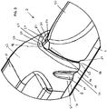
- a container 2 for sealing dispensable goods in a cavity.
- the container 2 includes a body 4 defining the cavity for receiving the dispensable goods.
- An upper edge 6 of the body 4 defines an opening of the cavity.
- a flange 8 of the container 2 extends from the upper edge 6 of the body 4.
- An upper surface 10 of the flange 8 has a generally flat surface for having a cover 12 affixed thereto.
- the body 4 and cover 12 provide a sealed environment for storage of the dispensable goods.
- the container 2 is fracturable across its width 14 along a specified break path 16. To ensure the integrity of the sealed environment within the container, the body 4 has a constant wall thickness 18, even along the break path 16.
- the body 4 includes an elongate construction, although other configurations are contemplated.
- the body 4 includes opposite ends 20 and 22 with an intermediate portion 24 positioned between the opposite ends 20 and 22.
- the break path 16 is positioned within the intermediate portion 24 of the body 4.
- the body 4 includes a handle portion 26 extending from the first end 20 to the break path 16, and a distal portion 28 extending from the second end 22 to the break path 16.
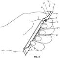
- the handle portion 26 is configured to be gripped by a user to allow for one-handed operation and use of the container 2.
- An engageable surface 30 of the distal portion 28 is configured to be engaged by a user, such as by a thumb of the user, to exert an opening force on the distal portion 28 of the body 4 so that the body 4 fractures along the break path 16. As shown in FIG. 3 , the engageable surface 30 is offset from a lower surface 31 of the handle portion 26 and arcuate, such as to approximate a finger, to provide an ergonomic engagement.
- the constant wall thickness 18 about the break path 16 reduces the tendency for the integrity of the container 2 to be unintentionally compromised during filling, handling and storage.
- the container 2 is configured to maximize the stress at a base surface 32 along the break path 16 of the container 2 as force is being exerted on the engageable surface 30 of the distal portion 28 of the body 4.
- the body 4 includes a bend 34 extending across the width 14 of the body 4 and which defines the break path 16.
- the container 2 includes a tapered profile 36 within the intermediate portion 24 of the body 4 and an enlarged flange portion 38 of the flange 8 adjoining the break path 16.
- the bend 34 of the body 4 is provided by the thermoforming process.
- a similar bend could be provided by bending a preformed body to provide a crease. Bending, however, may not be preferred because it may produce stress along the bend, which may reduce the overall strength of the body 4 and may lead to undesired fracturing. In contrast, the thermoformed bend 34 does not result in additional stress to the body 4.
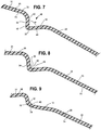
- the bend 34 of the body 4 provides additional stress on the base surface 32 of the bend 34 along the outer surface 33 of the body 4 as force is applied to the engageable surface 30 of the distal portion 28.
- the bend 34 straightens as force is applied to the engageable surface 30.
- FIG. 7 shows a cross section of the body 4 with no force being applied.
- the base surface 32 of the bend 34 is put under tension creating stress on the body 4.
- FIG. 9 once the stress along the base surface 32 exceeds the tension required to straighten the bend 34, the bend 34 straightens and a fracture 40 forms along the base surface 32 of the bend 34.
- the bend 34 defines the break path 16 along which a cleavage tear is propagated.
- the force required to initiate the fracture is greater than that required to propagate the tear along the break path 16.
- the container 2 is able to withstand higher stress and maintain a sealed condition, but allows for easy opening once the container 2 has been fractured.
- the bend 34 includes an angle oc defined by wall portions 42 and 44 of the body 4 located on either side of the bend 34.
- the angle oc is configured to promote fracturing along the bend 34.
- a larger angle oc provides increased stress along the bend 34 as the bend 34 is straightened.
- the angle ⁇ is at least about 70 degrees. In some cases, the angle oc ranges from about 70 to about 90 degrees.
- the body 4 includes other features to increase the amount of stress on the base surface 32 of the bend 34.
- the body 4 includes features to both increase the distance y between the neutral axis 58 and the base surface 32 of the bend 34 and decrease the second moment of area ( I x ), specifically at the desired rupture or break path 16.
- the tapered profile 36 of the body 4 about the break path 16 reduces the amount of material located away from the neutral axis 58. Further, the height of the body 4 is reduced at the break path 16 to specifically reduce the second moment of area ( I x ).
- the container 2 includes a neutral axis 58 along which point there is no longitudinal stress. More particularly, upon the application of force on the engageable surface 30, compressive stress acts on a portion 60 of the container 2 extending from the neutral axis 58 to the flange 8. Further, tensile stress acts on a portion 62 of the container 2 extending from the neutral axis 58 to the base surface 32.
- the location of the neutral axis 58 is determined based upon the shape of the container 2 and the distribution of mass. As shown in FIG. 4 , the location of the neutral axis 58 varies along the length of the container 2 as the shape or geometry of the body 4 changes. As described above, the Bernoulli-Euler equation represents that the stress at any given point of the container 2, as force is being applied to the engageable surface 30, is proportional to the distance y of that point from the neutral axis 58.
- the flange 8 of container 2 includes enlarged flange portions 38 along the intermediate portion 24 adjoining the break path 16.
- the enlarged flange portions 38 increase the mass of the flange 8 adjoining the break path 16 relative to the body 4.
- the increase of mass along the flange 8 shifts the neutral axis 58 within the intermediate portion 24 of the container 2 toward the flange 8 and away from the base surface 32 of the bend 34, as shown in FIG. 4 .
- the base surface 32 is further away from the neutral axis 58, thereby proportionally increasing the stress at the base surface 32 along the break path 16 and reducing the amount of force necessary to overcome the tensile strength of the body 4.
- the neutral axis 58 shifts toward the flange 8 until the break reaches the flange 8.
- the neutral axis 58 shifts toward the enlarged flange portions 38 due to the increased mass associated with the enlarged flange portions 38.
- the movement of the neutral axis 58 guides the tearing along the break path 16.
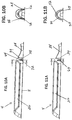
- the upper edge 6 of the body 4 includes inwardly extending portions 63 at the ends of the break path 16.
- the inwardly extending portions 63 correspond to the enlarged portions 38 of the flange 8, thereby providing a reduced width of the body 4 extending between the enlarged flange portions 38.
- flange 8 could extend inwardly or a combination of inwardly or outwardly from the upper edge 6 of the body 4.
- the body 4 includes the tapered profile 36, as shown in FIGS. 1 , 2 and 17-19 .
- the tapered profile 36 provides a reduced width 46 of the base surface 32, which concentrates the stress produced by the application of force on the engageable surface 30 in a smaller area. As a result, the amount of force necessary to generate sufficient stress to straighten the bend 34 of the body 4 is reduced as compared to a container having a wider body.
- the tapered profile 36 includes a peak 48 of the base surface 32 along the break path 16.
- the peak 48 can include an angular configuration 49, as shown in FIG 17 , to minimize the width 46 and thereby concentrate the stress on an even smaller area.
- the peak 48 can include a rounded configuration 50.
- the rounded configuration 50 also provides the reduced width 46 which is slightly larger than the width of the angular configuration 49. Although this requires more force to fracture the body 4, the resulting opening is larger and can accommodate a quicker and easier dispensation of the contents of the cavity.
- the tapered profile 36 In addition to reducing the width 46 of the base surface 32 of the body 4, the tapered profile 36 also affects the position of the neutral axis 58 due to the reduced material utilized to provide a tapered profile 36 as compared to a more squared-off profile. As a result, the neutral axis 58 shifts toward the flange 8 and away from the base surface 32, thereby further increasing the stress along the base surface 32 as force is applied to the engageable surface 30.
- the peak 48 can further include a nipple 52 on the rounded configuration 50 of the body 4.
- the nipple 52 extends from the rounded configuration 48 to provide an angular or almost angular base nipple surface 54.
- the base nipple surface 54 provides a nipple width 56 which would be less than the width 46 of the rounded configuration 48, but wider than an angular configuration 49.
- the nipple 52 may shift the neutral axis 58 away from the flange 8, the distance y between the base surface 32 and the neutral axis 58 increases by a larger amount.
- the nipple 52 thereby causes stress to concentrate along a smaller area, similar to what would be observed with an angular configuration 49, but provides an increased opening size associated with the rounded configuration 50.
- the container 2 includes inward protruding ribs 64 on the handle portion 26 of the body 4.
- the ribs 64 include a pair of spaced edges 66 and 68 opening to a recessed portion 70 of the body 4 and a corresponding widened section 72 of the flange 8.
- the ribs 64 provide relief from tensile stress along the body 4 as force is applied to the engageable surface 30. In particular, increased stress on the body 4 urges the spaced edges 66 and 68 away from one another, thereby flattening out the recessed portion 70 of the rib 64.
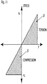
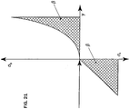
- the stress at individual locations along the body 4 is generally directly proportional to the distance y from the neutral axis 58, as shown in FIG. 20 .
- the average stress on the body 4 is the average of the stresses at the individual locations across the width of the body 4.
- the inclusion of ribs 64 acts to reduce the stress along the body 4 adjacent to the flange 8.
- stress along other portions of the body 4 increases so that the average stress along the body 4 does not change.
- the inclusion of ribs 64 causes stress to increase with distance y along a curve which more closely resembles an exponential curve than the linear relationship shown in FIG. 20 .
- the stress on the body 4 adjacent the flange 8 is reduced, while the stress at the base surface 32 is increased significantly.
- the recessed portions 70 of the ribs 64 are configured so that the widened sections 72 of the flange 8 adjoining the ribs 64 are not wider than the enlarged portion 38 of the flange 8 adjoining the break path 16. If the widened sections 72 were wider, the neutral axis 58 would be affected and the fracture would follow a ragged path toward the ribs 64 rather than a smooth, predefined path along the break path 16.
- the ribs 64 further provide structural strength to the container 2 to resist collapse of the container 2.
- the body 4 and flange 8 are preferably formed as a single member, as shown in FIGS. 1-4 .
- the body 4 and flange 8 can be formed by known processes, in particular thermoforming.
- the body 4 and flange 8 are preferably constructed of a material which is strong enough to be handled, filled and transported. Further, the material must be brittle enough to allow for the body 4 to be fractured along the bend 34. Preferably, the material has low tear propagation strength so that after the initial fracture of the bend 34, the cleavage can continue without excessive force.
- exemplary materials include natural or low-impact polystyrene, medium impact polystyrene, and biaxially oriented polystyrene.
- the body 4 has a wall thickness 18 selected to provide a robust container which can withstand the rigors of filling, distribution and handling.
- the constant wall thickness along the entire body 4 provides a constant level of protection along the container 2.
- a functional inner coating or layer can be applied to an inner surface 74 of the body 4.
- the inner coating provides additional safeguards, such as acting as a sealant or an oxygen barrier.
- the addition of coatings to the inner surface 74 of the body 4 does not affect the fracturing processes as the fracturing occurs and is initiated on the outer surface 33 of the body 4. As such, the coating is applied in an amount to provide functional properties, not to provide structural support.
- the cover 12 is made of a pliable material.
- the cover 12 may be affixed to the body 4 after the cavity is filled by a permanent adhesive seal, heat welding, or ultrasonic bonding.
- the outer cover material is selected to be able to act as a hinge between the handle portion 26 and the distal portion 28 once the bend 34 has been fractured. As such, the cover 12 is selected so as to not fracture or otherwise break as the body 4 is fractured.
- the cover 12 may be the same or different material than the body 4.
- the cover 12 may be made from a single layer of polymer sheet, such as polypropylene, or from a laminate material containing, for example, a combination of polymer, paper or aluminum foil layers.
- the cover 12 can be printed to identify the product or the contents stored in the container 2.
- the flange 8 can be configured to remain intact when the body is fractured and, with the cover 12, acts as a hinge between the handle portion 26 and the distal portion 28.
- the body 4 is configured to be recloseable as disclosed in U.S. Patent Application No. 11/771,372 filed June 29, 2007 , now US 8091242B .
- the wall portions 42 and 44 can be configured to provide a friction fit therebetween after the body 4 has been fractured.
- the wall portion 44 can include a protrusion 76 extending along the outer surface 30 thereof.
- the protrusion 76 can be configured to be received within the cavity and engage an inner surface 74 of the wall portion 42, thereby resisting pivoting of the distal portion 28 about the hinge.
Description
- The present invention relates generally to a container and, more particularly, to a fracturable container for opening.
- Containers are made from various materials, including glass, metal and plastic. Recently, plastic containers have been favored for their light weight construction and low cost. In particular, plastic containers can be made by known molding and thermoforming processes. In order to withstand shipping, handling and storage, the plastic should be robust. Preferred plastics today include PET and high-impact polystyrene. In particular, the plastics are selected so as to resist fracturing upon the application of expected and unexpected forces.
- Many of the known sealed containers include a body defining a cavity for receiving material and a lid or cover for sealing the cavity. In some containers, the cover is connected to the body by a mechanical interconnection, such as a snap-fit connection or threaded connection. In other containers, the cover can be connected to the body by adhesives and heat sealing. In some of these containers, the cover can be easily removed from the body to allow for access to the stored material. With small containers, however, removal of the cover can be difficult.
- Other containers can be configured so that cover remains connected to the body, and the body can be fractured upon the application of force. To provide a fracturable opening while maintaining the general strength of a container made from PET or high-impact polystyrene, one of the walls of the container will have a weakened section, such as a thinned wall section or perforations of the wall.
- Plastic containers, including a weakened section, are often made by a basic molding process, as the wall thickness can be varied during the molding process. Other plastic containers with a weakened section are thermoformed, where the weakened section is a result of cutting or perforating. Due to the reduced wall thickness associated with thermoformed containers, the weakened section is produced on generally flat sections of the containers so that a minimum wall thickness can be maintained, thereby providing a measure of structural stability, while weakening a section sufficiently to be fracturable.
- The weakened section allows the package to maintain a desired structural integrity inherent in the PET or high-impact polystyrene along the majority of the container body. However, by weakening a section of the container body, the container can be undesirably compromised by the application of force on the container body or as a result of internal pressure within the container, resulting in an unsealed container.
- To reduce the impact of employing a weakened section, known thermoformed containers position the weakened section to extend along a corner or otherwise smaller section of the container. The resulting small opening from this minimized weakened section does not provide for free flow of product stored in the cavity under the influence of gravity. While this aids in reducing unintended dispensation from the cavity, a user must squeeze or otherwise deform the container rather than simply tilting the container to dispense the contents.
- Many containers include an inner coating or layer to provide further protection for the contents. Although these coatings are effective for particular materials to be stored in the container or for particular environments, they are not intended to accommodate for the compromised integrity of the container body resulting from the weakened wall section.
-
US 3741384 discloses a sprinkle-packet for salt, pepper, or the like having a plastic body sealed to a paper backing. The plastic body includes a pocket and an elongate neck in communication with the pocket. When a user wishes to open the packet, he holds the neck at its uppermost end and bends the neck backwards to break open the package. The neck is stiff to concentrate rupturing action at the junction of the neck with the pocket. - The invention is in the container of Claim 1.
-
-
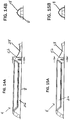
FIG. 1 is a perspective view of a container; -
FIG. 2 is an enlarged perspective view of an intermediate portion of the container ofFIG. 1 ; -
FIG. 3 is a perspective view of the container ofFIG. 1 being grasped by a user; -
FIG. 4 is a side elevational view of the container ofFIG. 1 and a graph showing the relative position of a neutral axis of the container along its length; -
FIG. 5 is an enlarged side elevational view of the intermediate portion of the container ofFIG. 1 ; -
FIG. 6 is an enlarged side elevational view of the intermediate portion of the container ofFIG.1 showing a partially fractured body; -
FIG. 7 is an enlarged cross-sectional view of the side elevational view of an intermediate portion of the container ofFIG. 1 ; -
FIG. 8 is an enlarged cross-sectional view of the side elevational view of an intermediate portion of the container ofFIG. 1 with a force being applied on the container; -
FIG. 9 is an enlarged cross-sectional view of the side elevational view of an intermediate portion of the container ofFIG. 1 showing a fractured lower surface as a result of a force being applied on the container; -
FIG. 10A is a side elevational view of the container ofFIG. 1 ; -
FIG. 10B is a cross-sectional view of an end elevational view of the container ofFIG. 10A ; -
FIG. 11A is a side elevational view of the container ofFIG. 1 ; -
FIG. 11B is a cross-sectional view of an end elevational view of the container ofFIG. 11A ; -
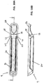
FIG. 12A is a side elevational view of the container ofFIG. 1 ; -
FIG. 12B is a cross-sectional view of an end elevational view of the container ofFIG. 12A ; -
FIG. 13A is a side elevational view of the container ofFIG. 1 ; -
FIG. 13B is a cross-sectional view of an end elevational view of the container ofFIG. 13A ; -
FIG. 14A is a side elevational view of the container ofFIG. 1 ; -
FIG. 14B is a cross-sectional view of an end elevational view of the container ofFIG. 14A ; -
FIG. 15A is a side elevational view of the container ofFIG. 1 ; -
FIG. 15B is a cross-sectional view of an end elevational view of the container ofFIG. 15A ; -
FIG. 16A is a plan view of the container ofFIG. 1 ; -
FIG. 16B is a side elevational, cross-sectional view of the container ofFIG. 16A ; -
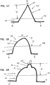
FIG. 17 is an end elevational, cross-sectional view of the container ofFIG. 1 along the bend showing an angular tapered profile and the neutral axis; -
FIG. 18 is an end elevational, cross-sectional view of the container ofFIG. 1 along the bend showing an alternative rounded tapered profile and the neutral axis; -
FIG. 19 is an end elevational, cross-sectional view of the container ofFIG. 1 along the bend showing an alternative rounded tapered profile with a nipple and the neutral axis; -
FIG. 20 is a graph comparing the linear relationship of stress and the distance y from the neutral axis; -
FIG. 21 is a graph comparing the relationship of stress and the distance y from the neutral axis with the container body including tension relieving ribs; and -
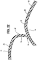
FIG. 22 is an enlarged cross-sectional view of the side elevational view of an intermediate portion of the container ofFIG. 1 showing a fractured body reclosed by the frictional engagement of a protrusion of a wall portion frictionally engaged with another wall portion. - In
FIG. 1 , acontainer 2 is shown for sealing dispensable goods in a cavity. Thecontainer 2 includes abody 4 defining the cavity for receiving the dispensable goods. Anupper edge 6 of thebody 4 defines an opening of the cavity. Aflange 8 of thecontainer 2 extends from theupper edge 6 of thebody 4. Anupper surface 10 of theflange 8 has a generally flat surface for having acover 12 affixed thereto. Thebody 4 and cover 12 provide a sealed environment for storage of the dispensable goods. In order to easily access the goods, thecontainer 2 is fracturable across itswidth 14 along a specifiedbreak path 16. To ensure the integrity of the sealed environment within the container, thebody 4 has aconstant wall thickness 18, even along thebreak path 16. - As shown in
FIGS. 1-3 , thebody 4 includes an elongate construction, although other configurations are contemplated. Thebody 4 includes opposite ends 20 and 22 with anintermediate portion 24 positioned between the opposite ends 20 and 22. As shown inFIGS. 1-9 , thebreak path 16 is positioned within theintermediate portion 24 of thebody 4. As shown inFIG. 3 , thebody 4 includes ahandle portion 26 extending from thefirst end 20 to thebreak path 16, and adistal portion 28 extending from thesecond end 22 to thebreak path 16. Thehandle portion 26 is configured to be gripped by a user to allow for one-handed operation and use of thecontainer 2. Anengageable surface 30 of thedistal portion 28 is configured to be engaged by a user, such as by a thumb of the user, to exert an opening force on thedistal portion 28 of thebody 4 so that thebody 4 fractures along thebreak path 16. As shown inFIG. 3 , theengageable surface 30 is offset from alower surface 31 of thehandle portion 26 and arcuate, such as to approximate a finger, to provide an ergonomic engagement. - As shown in
FIGS. 10A-16B , theconstant wall thickness 18 about thebreak path 16 reduces the tendency for the integrity of thecontainer 2 to be unintentionally compromised during filling, handling and storage. In order to provide increased structural integrity, thecontainer 2 is configured to maximize the stress at abase surface 32 along thebreak path 16 of thecontainer 2 as force is being exerted on theengageable surface 30 of thedistal portion 28 of thebody 4. - In particular, as shown in
FIGS. 1 ,2 , and4-9 , thebody 4 includes abend 34 extending across thewidth 14 of thebody 4 and which defines thebreak path 16. In addition, as shown inFIGS. 1 and2 , thecontainer 2 includes a taperedprofile 36 within theintermediate portion 24 of thebody 4 and anenlarged flange portion 38 of theflange 8 adjoining thebreak path 16. - The
bend 34 of thebody 4 is provided by the thermoforming process. A similar bend could be provided by bending a preformed body to provide a crease. Bending, however, may not be preferred because it may produce stress along the bend, which may reduce the overall strength of thebody 4 and may lead to undesired fracturing. In contrast, thethermoformed bend 34 does not result in additional stress to thebody 4. - The
bend 34 of thebody 4 provides additional stress on thebase surface 32 of thebend 34 along theouter surface 33 of thebody 4 as force is applied to theengageable surface 30 of thedistal portion 28. As shown inFIGS. 7-9 , thebend 34 straightens as force is applied to theengageable surface 30. In particular,FIG. 7 shows a cross section of thebody 4 with no force being applied. As shown inFIG. 8 , as force is being applied to theengageable surface 30, thebase surface 32 of thebend 34 is put under tension creating stress on thebody 4. As shown inFIG. 9 , once the stress along thebase surface 32 exceeds the tension required to straighten thebend 34, thebend 34 straightens and afracture 40 forms along thebase surface 32 of thebend 34. Once fractured, thebend 34 defines thebreak path 16 along which a cleavage tear is propagated. The force required to initiate the fracture is greater than that required to propagate the tear along thebreak path 16. As a result, thecontainer 2 is able to withstand higher stress and maintain a sealed condition, but allows for easy opening once thecontainer 2 has been fractured. - The
bend 34 includes an angle oc defined bywall portions body 4 located on either side of thebend 34. The angle oc is configured to promote fracturing along thebend 34. In particular, a larger angle oc provides increased stress along thebend 34 as thebend 34 is straightened. To provide the desired increased stress, the angle ∝ is at least about 70 degrees. In some cases, the angle oc ranges from about 70 to about 90 degrees. - As indicated above, the
body 4 includes other features to increase the amount of stress on thebase surface 32 of thebend 34. The stress at thebase surface 32 of thebend 34 can be characterized by the Bernoulli-Euler beam stress equation:
- σ - Average stress on the beam component.
- M' The moment about a
neutral axis 58 provided by the force applied atsurface 30. - y' The perpendicular distance from the
neutral axis 58 to the failure point, represented by thebase surface 32 of thebend 34 in anunfractured container 2. - Ix ' The second moment of area about the
neutral axis 58. - The
body 4 includes features to both increase the distance y between theneutral axis 58 and thebase surface 32 of thebend 34 and decrease the second moment of area (Ix ), specifically at the desired rupture or breakpath 16. The taperedprofile 36 of thebody 4 about thebreak path 16 reduces the amount of material located away from theneutral axis 58. Further, the height of thebody 4 is reduced at thebreak path 16 to specifically reduce the second moment of area (Ix ). - As shown in
FIGS. 4-6 , thecontainer 2 includes aneutral axis 58 along which point there is no longitudinal stress. More particularly, upon the application of force on theengageable surface 30, compressive stress acts on aportion 60 of thecontainer 2 extending from theneutral axis 58 to theflange 8. Further, tensile stress acts on aportion 62 of thecontainer 2 extending from theneutral axis 58 to thebase surface 32. The location of theneutral axis 58 is determined based upon the shape of thecontainer 2 and the distribution of mass. As shown inFIG. 4 , the location of theneutral axis 58 varies along the length of thecontainer 2 as the shape or geometry of thebody 4 changes. As described above, the Bernoulli-Euler equation represents that the stress at any given point of thecontainer 2, as force is being applied to theengageable surface 30, is proportional to the distance y of that point from theneutral axis 58. - To guide the fracturing of the
body 4 along thebreak path 16, theflange 8 ofcontainer 2 includesenlarged flange portions 38 along theintermediate portion 24 adjoining thebreak path 16. Theenlarged flange portions 38 increase the mass of theflange 8 adjoining thebreak path 16 relative to thebody 4. The increase of mass along theflange 8 shifts theneutral axis 58 within theintermediate portion 24 of thecontainer 2 toward theflange 8 and away from thebase surface 32 of thebend 34, as shown inFIG. 4 . As a result, thebase surface 32 is further away from theneutral axis 58, thereby proportionally increasing the stress at thebase surface 32 along thebreak path 16 and reducing the amount of force necessary to overcome the tensile strength of thebody 4. - As the
base surface 32 fractures and thebody 4 breaks, theneutral axis 58 shifts toward theflange 8 until the break reaches theflange 8. In particular, theneutral axis 58 shifts toward theenlarged flange portions 38 due to the increased mass associated with theenlarged flange portions 38. The movement of theneutral axis 58 guides the tearing along thebreak path 16. - As shown in
FIGS. 1 ,2 ,10B, 11B ,12B and 13B , theupper edge 6 of thebody 4 includes inwardly extendingportions 63 at the ends of thebreak path 16. The inwardly extendingportions 63 correspond to theenlarged portions 38 of theflange 8, thereby providing a reduced width of thebody 4 extending between theenlarged flange portions 38. - Alternatively, other configurations providing the
enlarged flange portion 38 are contemplated, including altering the thickness of theflange 8 adjacent thebreak path 16 or extending theflange 8 further outward. Further, it is contemplated that theflange 8 could extend inwardly or a combination of inwardly or outwardly from theupper edge 6 of thebody 4. - To further concentrate the stress along the
break path 16, thebody 4 includes the taperedprofile 36, as shown inFIGS. 1 ,2 and17-19 . The taperedprofile 36 provides a reducedwidth 46 of thebase surface 32, which concentrates the stress produced by the application of force on theengageable surface 30 in a smaller area. As a result, the amount of force necessary to generate sufficient stress to straighten thebend 34 of thebody 4 is reduced as compared to a container having a wider body. - The tapered
profile 36 includes apeak 48 of thebase surface 32 along thebreak path 16. The peak 48 can include anangular configuration 49, as shown inFIG 17 , to minimize thewidth 46 and thereby concentrate the stress on an even smaller area. Alternatively, as shown inFIGS. 18 , thepeak 48 can include arounded configuration 50. Therounded configuration 50 also provides the reducedwidth 46 which is slightly larger than the width of theangular configuration 49. Although this requires more force to fracture thebody 4, the resulting opening is larger and can accommodate a quicker and easier dispensation of the contents of the cavity. - In addition to reducing the
width 46 of thebase surface 32 of thebody 4, the taperedprofile 36 also affects the position of theneutral axis 58 due to the reduced material utilized to provide a taperedprofile 36 as compared to a more squared-off profile. As a result, theneutral axis 58 shifts toward theflange 8 and away from thebase surface 32, thereby further increasing the stress along thebase surface 32 as force is applied to theengageable surface 30. - The peak 48 can further include a
nipple 52 on the roundedconfiguration 50 of thebody 4. As best shown inFIGS. 2 and19 , thenipple 52 extends from the roundedconfiguration 48 to provide an angular or almost angularbase nipple surface 54. Thebase nipple surface 54 provides anipple width 56 which would be less than thewidth 46 of the roundedconfiguration 48, but wider than anangular configuration 49. While the addition of thenipple 52 may shift theneutral axis 58 away from theflange 8, the distance y between thebase surface 32 and theneutral axis 58 increases by a larger amount. Thenipple 52 thereby causes stress to concentrate along a smaller area, similar to what would be observed with anangular configuration 49, but provides an increased opening size associated with the roundedconfiguration 50. - As shown in
FIGS. 1 and2 , thecontainer 2 includes inward protrudingribs 64 on thehandle portion 26 of thebody 4. Theribs 64 include a pair of spacededges portion 70 of thebody 4 and a corresponding widenedsection 72 of theflange 8. Theribs 64 provide relief from tensile stress along thebody 4 as force is applied to theengageable surface 30. In particular, increased stress on thebody 4 urges the spaced edges 66 and 68 away from one another, thereby flattening out the recessedportion 70 of therib 64. - In the absence of the
ribs 64, the stress at individual locations along thebody 4 is generally directly proportional to the distance y from theneutral axis 58, as shown inFIG. 20 . The average stress on thebody 4 is the average of the stresses at the individual locations across the width of thebody 4. However, the inclusion ofribs 64 acts to reduce the stress along thebody 4 adjacent to theflange 8. As a result of the reduced stress along portions of thebody 4, stress along other portions of thebody 4 increases so that the average stress along thebody 4 does not change. As shown inFIG. 21 , the inclusion ofribs 64 causes stress to increase with distance y along a curve which more closely resembles an exponential curve than the linear relationship shown inFIG. 20 . As a result, the stress on thebody 4 adjacent theflange 8 is reduced, while the stress at thebase surface 32 is increased significantly. - As shown in
FIG. 10B , the recessedportions 70 of theribs 64 are configured so that the widenedsections 72 of theflange 8 adjoining theribs 64 are not wider than theenlarged portion 38 of theflange 8 adjoining thebreak path 16. If the widenedsections 72 were wider, theneutral axis 58 would be affected and the fracture would follow a ragged path toward theribs 64 rather than a smooth, predefined path along thebreak path 16. - The
ribs 64 further provide structural strength to thecontainer 2 to resist collapse of thecontainer 2. - The
body 4 andflange 8 are preferably formed as a single member, as shown inFIGS. 1-4 . Thebody 4 andflange 8 can be formed by known processes, in particular thermoforming. Thebody 4 andflange 8 are preferably constructed of a material which is strong enough to be handled, filled and transported. Further, the material must be brittle enough to allow for thebody 4 to be fractured along thebend 34. Preferably, the material has low tear propagation strength so that after the initial fracture of thebend 34, the cleavage can continue without excessive force. In particular, exemplary materials include natural or low-impact polystyrene, medium impact polystyrene, and biaxially oriented polystyrene. - The
body 4 has awall thickness 18 selected to provide a robust container which can withstand the rigors of filling, distribution and handling. The constant wall thickness along theentire body 4 provides a constant level of protection along thecontainer 2. - To accommodate specific materials being stored in the
container 2, or to provide an additional level of protection, a functional inner coating or layer can be applied to aninner surface 74 of thebody 4. The inner coating provides additional safeguards, such as acting as a sealant or an oxygen barrier. The addition of coatings to theinner surface 74 of thebody 4 does not affect the fracturing processes as the fracturing occurs and is initiated on theouter surface 33 of thebody 4. As such, the coating is applied in an amount to provide functional properties, not to provide structural support. - The
cover 12 is made of a pliable material. Thecover 12 may be affixed to thebody 4 after the cavity is filled by a permanent adhesive seal, heat welding, or ultrasonic bonding. The outer cover material is selected to be able to act as a hinge between thehandle portion 26 and thedistal portion 28 once thebend 34 has been fractured. As such, thecover 12 is selected so as to not fracture or otherwise break as thebody 4 is fractured. Thecover 12 may be the same or different material than thebody 4. For example, thecover 12 may be made from a single layer of polymer sheet, such as polypropylene, or from a laminate material containing, for example, a combination of polymer, paper or aluminum foil layers. Thecover 12 can be printed to identify the product or the contents stored in thecontainer 2. - The
flange 8 can be configured to remain intact when the body is fractured and, with thecover 12, acts as a hinge between thehandle portion 26 and thedistal portion 28. In some cases, thebody 4 is configured to be recloseable as disclosed inU.S. Patent Application No. 11/771,372 filed June 29, 2007 US 8091242B . - For example, the
wall portions body 4 has been fractured. In particular, as shown inFIG. 22 , thewall portion 44 can include aprotrusion 76 extending along theouter surface 30 thereof. Theprotrusion 76 can be configured to be received within the cavity and engage aninner surface 74 of thewall portion 42, thereby resisting pivoting of thedistal portion 28 about the hinge. - While the invention has been particularly described with specific reference to particular method and product embodiments, it will be appreciated that various alterations, modifications, and adaptations may be based on the present disclosure, and are intended to be within the scope of the invention as defined by the following claims.
Claims (15)
- A container (2) comprising:a body (4) having opposite ends (20 and 22), a width (14) and an intermediate portion (24) positioned between said opposite ends (20 and 22), said body (4) having at least one cavity for storing dispensable contents;an upper edge (6) of the body (4) defining an opening for filling the cavity;a flange (8) extending along the upper edge (6) of the body (4);a cover (12) affixed to the flange (8) to seal the dispensable contents within the cavity;a bend (34) extending across the width (14) of the intermediate portion (24) of the body (4) along which bend the body (4) fractures (16) upon the application of force exceeding a predetermined level on either side of the bend (34);a tapered profile (36) of the intermediate portion (24) of the body (4) for providing a reduced width of the body (4) so that stress concentrates along the reduced width as the force is applied on either side of the bend (34),and enlarged portions (38) of the flange (8) at the bend (34) configured to increase the mass of the flange (8) adjoining the bend (34) relative to the body, and thereby to shift a neutral axis (58) of the container (2) toward the flange (8) to provide increased stress along the bend (34) as the force is applied on either side of the bend (34), characterised in thatthe intermediate portion (24) of the body (4) being of constant wall thickness (18) throughout.
- The container (2) of claim 1 wherein the bend (34) generally defines an angle of about 70 degrees.
- The container (2) of claim 1 wherein the bend (34) generally defines an angle ranging from about 70 degrees to about 90 degrees.
- The container (2) of any one of claims 1-3 wherein the body (4) includes inward protruding ribs (64) spaced from the bend (34) to relieve tensile stress on the body (4) as force is applied on opposite sides of the bend (34).
- The container (2) of any one of claims 1-4 wherein the flange (8) extends outwardly from the upper edge (6) of the body (4).
- The container (2) of any one of claims 1-5 wherein the flange (8) has a generally constant wall thickness throughout (18).
- The container (2) of any one of claims claim 1-6 wherein the upper edge (6) of the body (4) includes a pair of inwardly extending portions (63) corresponding to the enlarged portion of the flange (38).
- The container (2) of any one of claims 1-7 wherein the tapered profile (36) includes an angular configuration (49) to reduce the width (46) at the intermediate portion (24).
- The container (2) of any one of claims 1-10 wherein the tapered profile (36) includes a rounded configuration (50) to reduce the width (46) at the intermediate portion (24).
- The container (2) of claim 1 wherein the bend has a rounded configuration and tapered profile (36) includes a nipple (52) having a width (56) less than a reduced width of the rounded configuration (50)to concentrate stress along the nipple (52).
- The container (2) of any one of claims 1-10 wherein the body (4) has a generally constant wall thickness thoughout the body (4).
- The container (2) of claim 10 further comprising inward protruding ribs (64), the ribs (64) being spaced from the bend (34) to relieve tensile stress on the body (4) as force is applied on opposite sides of the bend (34).
- The container (2) of claim 12 wherein the flange (8) includes a widened section (72) adjoining the ribs (64).
- The container (2) of claim 13 wherein the widened section (72) of the flange (8) adjoining the ribs (64) is not wider than the enlarged portion (38) of the flange (8).
- The container (2) of any one of claims 5 -14 wherein the ribs (64) include a pair of spaced edges (66) and (68) opening to a recessed portion (70) of the body (4).
Priority Applications (1)
| Application Number | Priority Date | Filing Date | Title |
|---|---|---|---|
| PL12754762T PL2681127T3 (en) | 2011-03-04 | 2012-02-06 | Fracturable container |
Applications Claiming Priority (2)
| Application Number | Priority Date | Filing Date | Title |
|---|---|---|---|
| US13/041,131 US8485360B2 (en) | 2011-03-04 | 2011-03-04 | Fracturable container |
| PCT/IB2012/000205 WO2012120344A2 (en) | 2011-03-04 | 2012-02-06 | Fracturable container |
Publications (3)
| Publication Number | Publication Date |
|---|---|
| EP2681127A2 EP2681127A2 (en) | 2014-01-08 |
| EP2681127A4 EP2681127A4 (en) | 2014-09-03 |
| EP2681127B1 true EP2681127B1 (en) | 2016-12-07 |
Family
ID=46752667
Family Applications (1)
| Application Number | Title | Priority Date | Filing Date |
|---|---|---|---|
| EP12754762.8A Active EP2681127B1 (en) | 2011-03-04 | 2012-02-06 | Fracturable container |
Country Status (13)
| Country | Link |
|---|---|
| US (1) | US8485360B2 (en) |
| EP (1) | EP2681127B1 (en) |
| JP (2) | JP6228015B2 (en) |
| KR (1) | KR101945456B1 (en) |
| CN (1) | CN103429504B (en) |
| AU (1) | AU2012226497B2 (en) |
| BR (1) | BR112013022389B1 (en) |
| DK (1) | DK2681127T3 (en) |
| ES (1) | ES2617674T3 (en) |
| HU (1) | HUE033665T2 (en) |
| PL (1) | PL2681127T3 (en) |
| PT (1) | PT2681127T (en) |
| WO (1) | WO2012120344A2 (en) |
Families Citing this family (18)
| Publication number | Priority date | Publication date | Assignee | Title |
|---|---|---|---|---|
| AU2004100000A4 (en) | 2004-01-02 | 2004-02-12 | Sands Innovations Pty Ltd | Dispensing stirring implement |
| US9718594B2 (en) * | 2012-02-10 | 2017-08-01 | The Gillette Company Llc | Oral care instrument and package therefore |
| JP6348331B2 (en) * | 2013-04-30 | 2018-06-27 | 清隆 楠瀬 | Distribution package |
| US20160090221A1 (en) * | 2013-05-23 | 2016-03-31 | Sands Innovations Ltd | Improved Container With Opening |
| USD739551S1 (en) * | 2014-03-20 | 2015-09-22 | Ceva Animal Health Llc | Pipette strip |
| WO2016065414A1 (en) * | 2014-10-27 | 2016-05-06 | Sands Innovations Ltd | Container having a fracturable opening arrangement |
| WO2016200396A1 (en) | 2015-06-12 | 2016-12-15 | Bemis Company, Inc. | Modified polyester sheet having snapability |
| USD778681S1 (en) * | 2015-07-23 | 2017-02-14 | Fang Yin Chen | Holder for cup-shaped capsule |
| WO2017015706A1 (en) * | 2015-07-24 | 2017-02-02 | Sands Innovations Ltd | Container having a fracturable opening arrangement for containing bait |
| US20170095100A1 (en) * | 2015-09-23 | 2017-04-06 | Robert W. White | Disposable eating utensil |
| US11286096B2 (en) * | 2016-03-30 | 2022-03-29 | Pouch Pac Innovations, Llc | Opening mechanism for plastic vial |
| USD774901S1 (en) * | 2016-04-13 | 2016-12-27 | Hypertherm, Inc. | Package |
| USD815519S1 (en) * | 2016-04-14 | 2018-04-17 | Hypertherm, Inc. | Electrode packaging |
| PT3248646T (en) * | 2016-05-25 | 2021-04-15 | Claudia Mattern | Two-part plastic blank set |
| EP3609802A4 (en) * | 2017-04-11 | 2020-04-08 | Sands Innovations Ltd | Fracturable container |
| US20210139216A1 (en) * | 2017-08-24 | 2021-05-13 | Spencer D. Sutherland | Dispensing device |
| US10753266B2 (en) * | 2018-05-16 | 2020-08-25 | GM Global Technology Operations LLC | J-groove for crack suppression |
| CN116685533A (en) * | 2020-12-23 | 2023-09-01 | 桑德斯创新有限公司 | Container |
Family Cites Families (449)
| Publication number | Priority date | Publication date | Assignee | Title |
|---|---|---|---|---|
| US1000178A (en) | 1910-05-21 | 1911-08-08 | William F Kahl | Medical spoon. |
| US1372325A (en) | 1919-04-09 | 1921-03-22 | Edward A Willemin | Folding knife-fork-and-spoon set |
| US1754973A (en) | 1928-04-14 | 1930-04-15 | Walch Herman | Condiment receptacle for knives, forks, and the like |
| US2654252A (en) | 1949-01-10 | 1953-10-06 | Ralph B Davis | Multiple measuring spoon |
| US2837822A (en) | 1957-10-07 | 1958-06-10 | Rachel E Wille | Fountain type feeding spoon |
| US3116152A (en) | 1959-01-22 | 1963-12-31 | Elmer L Smith | Baby food container and spoon combined |
| GB890770A (en) | 1959-07-31 | 1962-03-07 | American Hospital Supply Corp | Package for sterile articles |
| US3036700A (en) * | 1959-08-26 | 1962-05-29 | Becton Dickinson Co | Sterile hypodermic needle assembly and package |
| US3075639A (en) * | 1960-03-07 | 1963-01-29 | Baxter Laboratories Inc | Hypodermic needles in blister package |
| US3133679A (en) | 1961-04-05 | 1964-05-19 | Frank E Brown | Liquid dispensing device |
| US3154418A (en) | 1961-12-01 | 1964-10-27 | Bell & Richardson Inc De | Packaging and stirring implement for making beverages |
| GB1017425A (en) | 1963-03-29 | 1966-01-19 | Long & Hambly Ltd | Improvements in and relating to dispensing apparatus |
| FR1418834A (en) | 1964-04-30 | 1965-11-26 | Spoon provided with a housing intended to contain a product such as sugar | |
| US3428460A (en) | 1965-08-05 | 1969-02-18 | Laurice D Ely | Container type stirrer |
| US3410457A (en) | 1966-06-24 | 1968-11-12 | Chester A. Brown | Seasoning fork |
| AT278563B (en) | 1967-02-14 | 1970-02-10 | Schmalbach Lubeca | Closing lid made of plastic |
| US3521805A (en) | 1968-09-27 | 1970-07-28 | Anderson Bros Mfg Co | Dispensing packet |
| US3620676A (en) | 1969-02-20 | 1971-11-16 | Sterilizer Control Royalties A | Disposable colorimetric indicator and sampling device for liquids |
| US3581885A (en) * | 1969-09-26 | 1971-06-01 | Keystore Consolidated Ind Inc | Blister package |
| FR2063745A5 (en) | 1969-10-30 | 1971-07-09 | Thevenin Jean | |
| DE6946391U (en) | 1969-11-29 | 1970-05-14 | Koellner Sigrune | MULTI-CHAMBER CONTAINER FOR THE SEPARATE ACCOMMODATION OF REACTING SUBS ANZES FOR THE MANUFACTURING OF READY-TO-USE DENTAL PREPARATIONS. |
| US3618751A (en) | 1970-01-15 | 1971-11-09 | Joseph Nichlos | Crushing and dispensing container for administering pills |
| US3648369A (en) | 1970-03-09 | 1972-03-14 | Dudley Lyon | Eating implement |
| US3635376A (en) | 1970-06-05 | 1972-01-18 | Hellstrom Harold R | Quick-open flexible package |
| DE2124931A1 (en) | 1971-05-19 | 1972-11-30 | Hamac-Hansella Gmbh, 4060 Viersen | Plastic film blister pack - with sealing strip covering the opening having non-adhesive gripping edge |
| US3741384A (en) * | 1971-12-03 | 1973-06-26 | Cloud Machine Corp | Individual sprinkle-packet with ribbed break-open neck |
| US3776375A (en) * | 1972-01-25 | 1973-12-04 | Packaging Ind Inc | Free-standing blister package |
| US3911578A (en) | 1972-05-10 | 1975-10-14 | Meyer Ushkow | Spoon constructions |
| DE2232861A1 (en) * | 1972-07-05 | 1974-01-17 | Bosch Verpackungsmaschinen | BLISTER PACK |
| US3835995A (en) | 1972-07-12 | 1974-09-17 | Paco Packaging | Tamperproof package |
| US3913734A (en) | 1972-08-03 | 1975-10-21 | Pharmacare Inc | Package assembly |
| US3921805A (en) | 1972-10-10 | 1975-11-25 | Newton L Compere | Rupturable blister pill package with safety backing |
| DE7237741U (en) | 1972-10-14 | 1973-06-20 | Henkel & Cie Gmbh | Disposable cutlery with spice chamber |
| US3986640A (en) | 1973-08-20 | 1976-10-19 | Sanford Redmond | Package for a flowable product and material for making such package |
| US3948394A (en) | 1973-09-28 | 1976-04-06 | Hellstrom H Richard | Child-proofed quick-opening package |
| US3872970A (en) | 1974-01-11 | 1975-03-25 | Lilly Co Eli | Child-resistant blister package |
| US3891331A (en) | 1974-06-14 | 1975-06-24 | Marion Health & Safety Inc | Unit for dispensing liquid from a frangible ampoule |
| US3946652A (en) | 1974-08-06 | 1976-03-30 | Sylvan Gorin | Dispensing spoon |
| US4005776A (en) * | 1975-05-02 | 1977-02-01 | Plastofilm Industries, Inc. | Package for oral thermometer, catheter or the like |
| US4011949A (en) | 1975-06-18 | 1977-03-15 | The Lehigh Press, Inc. | Package construction for opening only by a predetermined procedure |
| DE7523870U (en) | 1975-07-26 | 1976-11-18 | Szperkowski, Reiner G., 5474 Brohl | Eating cutlery with integrated oil dispensers |
| US4106621A (en) | 1976-07-26 | 1978-08-15 | Sorenson Research Co., Inc. | Combination needle cover and venipuncture device tray and method of using same |
| US4155454A (en) | 1977-01-12 | 1979-05-22 | Schering Corporation | Safety packaging for ampoules |
| US4218155A (en) | 1978-02-10 | 1980-08-19 | Etablissements Armor, S.A. | Stick for applying a liquid |
| USD259533S (en) | 1978-08-31 | 1981-06-16 | Howard L. Huntington | Spoon straw |
| US4266667A (en) * | 1978-10-23 | 1981-05-12 | Sakura Color Products Corporation | Package of mechanical pencil refill leads |
| US4236652A (en) | 1979-03-20 | 1980-12-02 | American Can Company | Dispenser package |
| US4231496A (en) | 1979-04-02 | 1980-11-04 | Gilson Channing W | Food dispensing utensil |
| USD263074S (en) | 1979-09-14 | 1982-02-16 | Mason-Keller Corporation | Culture swab transport package with rupturable sealed section having a stored culture medium |
| US4275646A (en) | 1979-09-17 | 1981-06-30 | Barna Stephen L | Kitchen utensil for making flavored beverages |
| US4277194A (en) | 1979-09-20 | 1981-07-07 | Smith Donald R | Paste dispensing toothbrush |
| US4317284A (en) | 1980-03-21 | 1982-03-02 | Prindle William A | Flatware eating utensils |
| US4331255A (en) | 1980-08-18 | 1982-05-25 | Fournier George J | Cup cover |
| US4341302A (en) | 1980-10-15 | 1982-07-27 | United Fillers Pty. Ltd. | Storing and mixing apparatus |
| US4338338A (en) | 1980-11-24 | 1982-07-06 | Popkes Opal L | Beverage strainers |
| US4387809A (en) | 1981-05-01 | 1983-06-14 | Botzler Paul C | Multi-compartment combination package and stirrer device |
| USD275517S (en) | 1982-01-18 | 1984-09-11 | Johnson & Johnson Dental Products Company Fr. | Dental composite unit dose tray |
| US4493574A (en) * | 1982-11-18 | 1985-01-15 | Sanford Redmond | Dispenser package having fault line protrusion |
| USD281813S (en) | 1983-01-26 | 1985-12-17 | Johnson & Johnson Dental Products Company | Dental composite unit dose container with breakaway mixing stick |
| USD281719S (en) | 1983-01-26 | 1985-12-10 | Johnson & Johnson Dental Products Company | Dental composite unit dose container with attached mixing stick |
| US4499353A (en) * | 1983-03-03 | 1985-02-12 | Usm Corporation | Blister package |
| DE8333430U1 (en) | 1983-11-22 | 1984-02-16 | Rittich, Boje, Dr. | FULL TOOTHBRUSH |
| US4611715A (en) | 1984-10-16 | 1986-09-16 | Sanford Redmond | Dispenser package |
| US4615120A (en) | 1984-12-21 | 1986-10-07 | Continental Can Company, Inc. | Collapsible spoon |
| US4655627A (en) | 1985-05-17 | 1987-04-07 | Bradley George G | Brush with self-sealing reservoir having a convertible actuator |
| US4687129A (en) * | 1985-09-06 | 1987-08-18 | Vsi Fasteners, Inc. | Reusable container |
| US4602719A (en) | 1985-10-03 | 1986-07-29 | Placon Corporation | Reclosable plastic container having improved opening release |
| US4830222A (en) | 1986-01-28 | 1989-05-16 | Read Avis O | Combination spoon and food container |
| US4724982A (en) | 1986-12-18 | 1988-02-16 | Sanford Redmond | Asymmetric stress concentrator for a dispenser package |
| JPH031419Y2 (en) | 1987-01-08 | 1991-01-17 | ||
| ATE68435T1 (en) * | 1987-03-06 | 1991-11-15 | Baker Cummins Pharma | PACKAGE FOR ADMINISTRATION OF A MEDICATION PREPARATION. |
| NL8701700A (en) | 1987-07-17 | 1989-02-16 | Heijenga S Management B V | HOLDER FOR A LIQUID OR PASTIC PRODUCT. |
| US4784268A (en) * | 1987-07-20 | 1988-11-15 | Plastofilm Industries, Inc. | Stand-up or hanging display blister and package |
| DE3730507A1 (en) | 1987-09-11 | 1989-03-23 | Werner Scholzen | CUTLERY PART, ESPECIALLY SPOON, FOR ONE-WAY USE |
| FR2622424A1 (en) | 1987-10-29 | 1989-05-05 | Rambin Christian | Spoon for food use |
| US5009894A (en) | 1988-03-07 | 1991-04-23 | Baker Cummins Pharmaceuticals, Inc. | Arrangement for and method of administering a pharmaceutical preparation |
| US4888188A (en) | 1988-05-09 | 1989-12-19 | Castner Sr John F | Disposable food feeder package |
| US4871091A (en) | 1988-09-29 | 1989-10-03 | Mason-Keller Corporation | Disposable package for liquids |
| US4891232A (en) | 1988-10-11 | 1990-01-02 | Dahl Derek W | Beverage infusion device |
| US5067822A (en) | 1989-04-24 | 1991-11-26 | Reynolds Consumer Products, Inc. | Method of forming recloseable packages, profiles used therein, and packages produced thereby |
| ATE119842T1 (en) | 1989-07-01 | 1995-04-15 | Nestle Sa | FOOD PACKAGING. |
| US4922611A (en) | 1989-07-26 | 1990-05-08 | Isy Levy | Knife/fork/spoon combination cutlery |
| US5048715A (en) | 1989-09-07 | 1991-09-17 | Dart Industries, Inc. | Closure assembly with hinged cover |
| FR2653746A1 (en) | 1989-10-26 | 1991-05-03 | Merck Sharp & Dohme | STERILE PACKAGING ASSEMBLY FOR DISPENSING LIQUID, AND METHOD FOR MANUFACTURING SUCH A ASSEMBLY. |
| US5409125A (en) | 1989-12-11 | 1995-04-25 | Aktiebolaget Astra | Unit dose container |
| DE3941183A1 (en) | 1989-12-13 | 1991-06-20 | Multivac Haggenmueller Kg | PACKING MACHINE FOR PRODUCING A RECOVERABLE PACKAGING WITH A PRODUCT |
| US5125528A (en) | 1989-12-18 | 1992-06-30 | Polystar Packaging, Inc. | Container closure, and method for producing same |
| BE1003570A3 (en) | 1990-01-26 | 1992-04-21 | Dekeyser Michel | Storage device and pasty material dose distribution and method of realization. |
| US4938462A (en) * | 1990-02-12 | 1990-07-03 | Gould Charles E | Resealable package |
| US5154318A (en) | 1990-03-02 | 1992-10-13 | Lampard Lucille B | Infants pacifier and feeder apparatus |
| US5240415A (en) | 1990-06-07 | 1993-08-31 | Haynie Michel B | Dental bleach system having separately compartmented fumed silica and hydrogen peroxide and method of using |
| USD327013S (en) | 1990-08-29 | 1992-06-16 | Cooper Industries, Inc. | Packaging container |
| US5027947A (en) | 1990-08-29 | 1991-07-02 | Cooper Industries, Inc. | Reclosable sleeved blister package |
| US5119560A (en) | 1991-01-07 | 1992-06-09 | Apothecary Products, Inc. | Medicine dosage device |
| USD334058S (en) | 1991-01-07 | 1993-03-16 | Apothecary Products, Inc. | Combined dosage spoon and container |
| US5125534A (en) | 1991-01-14 | 1992-06-30 | Rose Barry L | Beverage flavoring and dispensing apparatus and method of construction |
| CN2081671U (en) | 1991-02-07 | 1991-07-31 | 卢青海 | Convenient toothbrush |
| USD340408S (en) | 1991-02-26 | 1993-10-19 | Hirsch Armbander Gesellschaft mbH | Shipping container for jewelry items and watch bands |
| US5154293A (en) | 1991-04-23 | 1992-10-13 | Gould Charles E | Resealable package |
| US5203459A (en) | 1991-05-14 | 1993-04-20 | Wade Leslie C | Prepackaged oral medication serving apparatus and method |
| US5238157A (en) | 1991-05-24 | 1993-08-24 | Aliseo Gentile | Squeezeable container and integral cap formed from a laminated flat blank |
| US5251758A (en) | 1991-07-15 | 1993-10-12 | Liblan & Co., Ltd. | Food container with grippable portion having sense of touch indicia |
| FR2680456A1 (en) | 1991-08-20 | 1993-02-26 | Cristea Dorin | Brush with reservoir |
| USD330481S (en) | 1991-10-07 | 1992-10-27 | Green Lori L | Spoon straw |
| CH683910A5 (en) | 1991-11-14 | 1994-06-15 | Zentralschweizerischer Milchve | Container for receiving a comestible. |
| US6348246B1 (en) | 1992-01-09 | 2002-02-19 | Arnold B. Finestone | Laminate sheeting for pouches |
| US5209354A (en) * | 1992-02-11 | 1993-05-11 | Newell Operating Company | Reusable blister package |
| US5395031A (en) | 1992-03-10 | 1995-03-07 | Redmond; Sanford | Stress concentrator aperture-forming means for sealed containers and packages |
| US5308008A (en) | 1992-03-18 | 1994-05-03 | Rueegg Anton | Method and apparatus for producing rolls |
| USD344058S (en) | 1992-05-01 | 1994-02-08 | Jones Henry J | Brake plate |
| USD362304S (en) | 1992-05-01 | 1995-09-12 | Waverly Pharmaceutical, Ltd. | Ampoule array |
| US5215221A (en) | 1992-05-07 | 1993-06-01 | The Procter & Gamble Company | Disposable unit dose dispenser for powdered medicants |
| DE4216149A1 (en) | 1992-05-15 | 1993-11-18 | Multivac Haggenmueller Kg | Packaging machine |
| DE4226797A1 (en) | 1992-08-13 | 1994-02-17 | Gea Finnah Gmbh | Sterile filling of food into containers formed from plastic foil - by steam sterilising lengths of flat foil on both sides before shaping into container and cover and keeping in sterile atmos. until closing. |
| CA2103830C (en) | 1992-08-19 | 2005-05-17 | Gerald M. Syrek | Stackable container for premoistened wipes |
| FR2697331A1 (en) | 1992-10-26 | 1994-04-29 | Langlois Marc | Spoon for dispensing medicine, e.g. in hospital or chemists - has medicine contained in spoon cup by sealing film which also provides protection against heat |
| ATE177708T1 (en) | 1992-10-28 | 1999-04-15 | Anton Rueegg | DEVICE FOR WINDING A CONTINUOUSLY FEEDED MATERIAL WEB INTO A NUMBER OF WINDING CORE |
| USD347277S (en) | 1992-11-20 | 1994-05-24 | John Snedden | Pre-measured dispensing ampule |
| US5277103A (en) | 1992-11-23 | 1994-01-11 | Melange International, Inc. | Personal coffee brewing device |
| US5241835A (en) | 1992-12-30 | 1993-09-07 | David Ascone | Milk and cereal container |
| US5238179A (en) | 1993-01-04 | 1993-08-24 | Jefferson Smurfit Corporation | Top opening carton with integral internal handle |
| USD358466S (en) | 1993-01-28 | 1995-05-16 | Ciba-Geigy Corporation | Dispenser for ophthalmic solution |
| DE4304337A1 (en) | 1993-02-13 | 1994-08-25 | Gea Finnah Gmbh | Method and device for filling and closing a double chamber cup made of plastic |
| US5305928A (en) | 1993-06-04 | 1994-04-26 | Roberto Verdaguer | Squeezable feeding container |
| US5529224A (en) | 1993-11-01 | 1996-06-25 | The Procter & Gamble Company | Self-closing liquid dispensing package |
| CH686885A5 (en) | 1993-11-26 | 1996-07-31 | Anton Ruegg | Method and device for winding web-shaped material. |
| US5377879A (en) | 1993-12-22 | 1995-01-03 | Isaacs; Linda R. F. | Measuring spoon |
| DE9401117U1 (en) | 1994-01-24 | 1995-05-18 | Illig Maschinenbau Adolf | packaging |
| BE1008054A5 (en) | 1994-02-01 | 1996-01-03 | Pierret Johan | Single use disposable spoon equipped with previously filled and sealed milkand sugar reservoirs for addition to and stirring of coffee and tea or otherbeverages |
| US5411178A (en) | 1994-03-11 | 1995-05-02 | Beeton Holdings Limited | Fluid dispenser pouch with venturi shaped outlet |
| USD375352S (en) | 1994-03-14 | 1996-11-05 | Columbia Laboratories, Inc. | Dispensing vial for feminine hygiene products |
| US5494252A (en) | 1994-08-17 | 1996-02-27 | Biobright Corporation | Device and method for effecting relative motion within a closed sales display package |
| US5440976A (en) | 1994-08-23 | 1995-08-15 | Fred Giuliano | Adjustable dispensing stirrer for soluble sweeteners |
| SI9400348A (en) | 1994-09-08 | 1996-04-30 | Janez Zugman | Teaspoon |
| USD375353S (en) | 1994-10-14 | 1996-11-05 | Wolff Stephen H | Medication dosing spoon |
| US5477660A (en) | 1994-11-01 | 1995-12-26 | Multivac Sepp Haggenmuller Kg | Process and apparatus for maximizing vacuum packaging machine cycle rate |
| US5695084A (en) | 1994-11-04 | 1997-12-09 | Chmela; John F. | Disposable one-piece container closure and eating utensil |
| US5491895A (en) | 1994-12-05 | 1996-02-20 | Lee; Denise D. | Cold cereal spoon |
| SE505294C2 (en) | 1994-12-13 | 1997-07-28 | Regath Hb | Resealable packaging with means for indicating if the packaging is broken |
| US5582330A (en) | 1994-12-28 | 1996-12-10 | Allergan, Inc. | Specific volume dispenser |
| US5676244A (en) | 1995-04-04 | 1997-10-14 | Green; Robert | Food container |
| USD375055S (en) | 1995-04-10 | 1996-10-29 | Reed Robert R | Measuring spoon |
| US5579957A (en) | 1995-04-25 | 1996-12-03 | Chesebrough-Pond's Usa Co., Division Of Conopco, Inc. | Child-resistant closure |
| US5755330A (en) | 1995-05-22 | 1998-05-26 | Block Drug Company, Inc. | Multiple compacted solids and packages thereof |
| US5577627A (en) | 1995-06-07 | 1996-11-26 | Tenneco Packaging | Hinge structure for thermoformed plastic containers |
| CN1196709A (en) | 1995-08-04 | 1998-10-21 | 桑敦投资有限公司 | Breakable sack |
| US5676280A (en) | 1995-08-04 | 1997-10-14 | Illinois Tool Works Inc. | Anti cross-contamination dual cartridge dispenser |
| US5705212A (en) | 1995-09-08 | 1998-01-06 | Atkinson; Patrick J. | Food package with an enclosed eating utensil |
| IT1277043B1 (en) | 1995-12-06 | 1997-11-04 | Dompe Spa | PRE-DOSED CONTAINER FOR SINGLE-DOSE PEELABLE ADMINISTRATIONS ACCORDING TO THE RELEVANT PRODUCTION METHOD |
| TR199801435T2 (en) | 1996-01-23 | 1999-05-21 | Redmond Sanford | Resealable dosage pack. |
| US6299012B1 (en) | 1996-01-23 | 2001-10-09 | Sanford Redmond | Reclosable dispenser package, reclosable outlet forming structure and method and apparatus for making same |
| CA2243660A1 (en) | 1996-02-02 | 1997-08-07 | Sanford Redmon | Improved coffee creamer and other cups and tubs |
| USD402546S (en) | 1996-02-13 | 1998-12-15 | Gea Finnah Gmbh | Double chamber cup |
| US5826737A (en) | 1996-02-20 | 1998-10-27 | Colgate-Palmolive Company | Thermoformed reclosable container |
| US5706980A (en) | 1996-04-01 | 1998-01-13 | Dickerson; Albert Myron | Comestibles consumption device |
| US5676990A (en) | 1996-04-29 | 1997-10-14 | Wawrzynski; David W. | Method of food article dipping and wiping in a condiment container |
| US6412653B1 (en) | 1996-05-03 | 2002-07-02 | Carter Holt Harvey Limited | Plastic moulded container with detachable eating utensil |
| IT1287446B1 (en) | 1996-06-18 | 1998-08-06 | Unifill Int Ag | PACKAGING UNIT FOR FLUID PRODUCTS |
| US5827535A (en) | 1996-06-21 | 1998-10-27 | Banner Pharmacaps, Inc. | Graphically impressed softgel and method for making same |
| DE19627243A1 (en) | 1996-07-08 | 1998-01-15 | Hassia Verpackung Ag | Packaging for two filling material components for oral administration of medication |
| SI9600327A2 (en) | 1996-11-07 | 1998-06-30 | Cuilleree D.O.O. | Spoon with sweetener dispenser |
| AU728336B2 (en) | 1996-12-09 | 2001-01-04 | Bausch & Lomb Incorporated | Single-use flexible container |
| BR9806850A (en) | 1997-01-07 | 2000-03-14 | Gea Finnah Gmbh | Process and machine for preparing bottles for filling and filling bottles |
| US5792496A (en) | 1997-01-10 | 1998-08-11 | Fekete; Ferenc | Edible shell/thermoplastic container system |
| FR2758795B1 (en) | 1997-01-24 | 1999-02-26 | Oreal | PACKAGING FOR LIQUID TO SEMI-LIQUID PRODUCT |
| US5979657A (en) | 1997-02-13 | 1999-11-09 | Bumbera; Steve | Combination stirrer and condiment dispenser |
| USD408278S (en) | 1997-03-04 | 1999-04-20 | Gillette Canada Inc. | Blister package for a toothbrush |
| US6116450A (en) | 1997-03-18 | 2000-09-12 | Huang; Shou Li | Cover structure with integral utensil means for canned and cupped food |
| US6003710A (en) | 1997-03-18 | 1999-12-21 | Huang; Shou Li | Cover structure with integral utensil means for canned and cupped food |
| US5950859A (en) | 1997-03-25 | 1999-09-14 | Ball Corporation | Container with sealing member |
| AU6378798A (en) | 1997-05-02 | 1998-11-05 | Alexander Michael Gillichrist MacNaghten | Storage device |
| US5944516A (en) | 1997-05-29 | 1999-08-31 | Deshaies; Brian | Animal tooth cleaning device and method |
| USD398843S (en) | 1997-06-06 | 1998-09-29 | Georg Wiegner | Package for a toothbrush |
| DE19727942C2 (en) | 1997-07-01 | 1999-04-15 | Gea Finnah Gmbh | Machine and method for closing bottles with caps |
| USD407640S (en) | 1997-07-18 | 1999-04-06 | S. C. Johnson & Son, Inc. | Dispenser package |
| US5873167A (en) | 1997-08-06 | 1999-02-23 | Mason; Grady R. | Condiment utensil |
| DE59709858D1 (en) | 1997-08-08 | 2003-05-22 | Multivac Haggenmueller Kg | Lifting device for a work station of a packaging machine |
| DE19734513A1 (en) | 1997-08-08 | 1999-02-11 | Multivac Haggenmueller Kg | Lifting device for a work station of a packaging machine |
| US5839609A (en) | 1997-08-27 | 1998-11-24 | Colgate-Palmolive Company | Thermoformed pack with ridge valve |
| USD403512S (en) | 1997-09-29 | 1999-01-05 | Daniel Hennings | Combined toothbrush and toothpaste dispenser |
| USD408217S (en) | 1998-01-09 | 1999-04-20 | Calphalon Corporation | Utensil handle |
| AU139139S (en) | 1998-03-17 | 1999-12-09 | Pi Design Ag | A fork |
| CA2365527A1 (en) | 1998-03-18 | 1999-09-23 | Sanford Redmond | Tubelike dispenser package and integral outlet formed from a single sheet |
| US6364203B2 (en) | 1998-03-19 | 2002-04-02 | The Procter & Gamble Company | Articulable food container |
| FR2778639B1 (en) | 1998-05-18 | 2000-07-28 | Valois Sa | SAMPLE TYPE SPRAYING DEVICE |
| US5975305A (en) | 1998-06-25 | 1999-11-02 | Comar, Inc. | Unit dose spoon |
| JP4216367B2 (en) | 1998-06-25 | 2009-01-28 | ニュー・グッズ株式会社 | Daily necessities with filling containers |
| US6453562B1 (en) | 1998-08-24 | 2002-09-24 | Nouri E. Hakim | Baby spoons and method of manufacture |
| US6336310B1 (en) | 1998-09-08 | 2002-01-08 | Sanford Redmond | Method and apparatus for making compact packages for speadable product |
| AU136830S (en) | 1998-09-09 | 1999-03-23 | Life Therapeutics Ltd | Cartridge |
| US6007246A (en) | 1998-09-29 | 1999-12-28 | Kraft Foods Inc. | Reclosable container arrangement |
| GB2375040B (en) | 1998-10-07 | 2003-04-09 | Christina Elsender | Disposable reservoir toothbrush |
| USD419063S (en) | 1998-10-21 | 2000-01-18 | Gillette Canada Inc. | Toothbrush package |
| US6105259A (en) | 1998-10-22 | 2000-08-22 | Gerber Products Company | Eating utensils |
| US6024219A (en) | 1998-10-30 | 2000-02-15 | Kraft Foods, Inc. | Display packages |
| GB9824159D0 (en) | 1998-11-04 | 1998-12-30 | Venalink Ltd | Medicine packs |
| US6287612B1 (en) | 1998-12-01 | 2001-09-11 | Nestec S.A. | Liquid food products and package therefore |
| DE29821687U1 (en) | 1998-12-05 | 2000-04-06 | Gea Finnah Gmbh | Device for producing an aerosol |
| DE29821746U1 (en) | 1998-12-07 | 2000-04-13 | Gea Finnah Gmbh | Device for transporting bottles |
| USD425617S (en) | 1998-12-28 | 2000-05-23 | John Snedden | Resilient ampule with angulated spout for medicaments |
| US6070723A (en) | 1999-01-11 | 2000-06-06 | Portage Plastics Corp. | Reclosable package and method |
| USD426708S (en) | 1999-01-21 | 2000-06-20 | Gary Francis | Disposable toothbrush with toothpaste and mouth wash |
| US6209748B1 (en) | 1999-02-04 | 2001-04-03 | Lee Wayne Dunbar | Condiment-carrying lid |
| DE19904649A1 (en) | 1999-02-05 | 2000-10-12 | Daniel Woehl | Animal brush has compartment in back which can be filled with medicament or other animal care composition which is applied as the animal is brushed |
| US6395317B1 (en) | 1999-02-11 | 2002-05-28 | Mars Incorporated | Process and apparatus for forming dual compartment pouches from a continuous web |
| US6153232A (en) | 1999-02-11 | 2000-11-28 | Uncle Ben's, Inc. | Boil-in-bag package |
| US20030066870A1 (en) | 1999-02-13 | 2003-04-10 | Stewart Noel G. | Tubular container with side opening |
| US6910623B2 (en) | 1999-02-13 | 2005-06-28 | Smurfit-Stone Container Enterprises, Inc. | Paperboard can with an integrated lid having a hinge on the lid |
| US6390358B1 (en) | 1999-02-13 | 2002-05-21 | Stone Container Corporation | Paperboard can with an integrated paperboard lid having a hinge on the lid |
| US6471122B1 (en) | 1999-02-13 | 2002-10-29 | Stone Container Corporation | Paperboard can with an integrated paperboard lid having a slide closure |
| US6349866B1 (en) | 1999-02-13 | 2002-02-26 | Stone Container Corporation | Paperboard can with an integrated paperboard lid having a hinge on the lid |
| US6372176B1 (en) | 1999-03-01 | 2002-04-16 | Kiefel Technologies Inc. | System and method for twin sheet forming |
| DE19912491A1 (en) | 1999-03-19 | 2000-09-28 | Multivac Haggenmueller Gmbh | Packaging machine |
| DE19915040A1 (en) | 1999-04-01 | 2000-10-12 | Multivac Haggenmueller Gmbh | Device and method for separating a film with at least two laminate layers and packaging machine with such a device and packing with an upper film made of at least two laminate layers |
| DE29908075U1 (en) | 1999-05-06 | 2000-09-14 | Gea Finnah Gmbh | Device for closing plastic bottles |
| DE19921668C1 (en) | 1999-05-11 | 2001-01-04 | Illig Maschinenbau Adolf | Method for moving a swivel table in a device for forming and punching out containers from a thermoplastic film and device for carrying out the method |
| US6213662B1 (en) | 1999-05-13 | 2001-04-10 | Mohdsameer Y Aljanedi | Toothbrush with paste dispenser |
| US6279233B1 (en) | 1999-05-17 | 2001-08-28 | Ralecia L. Cameron | Self contained feeding spoon |
| GB9911332D0 (en) | 1999-05-17 | 1999-07-14 | Barnes Susan | Food container |
| US6159513A (en) | 1999-05-27 | 2000-12-12 | Mott's, Inc. | Package and method for packaging and preparing a mixed drink |
| JP2000333811A (en) | 1999-05-27 | 2000-12-05 | Kunito Hayashi | Portable chopsticks with capsule to be bisected accessories |
| GB2351272B (en) | 1999-06-23 | 2001-05-02 | Eu Pharma Ltd | Oral medicine dispenser |
| IT248511Y1 (en) | 1999-07-14 | 2003-02-04 | Lameplast Srl | SINGLE DOSE BOTTLE FOR DRINKABLE LIQUIDS, PARTICULARLY PHARMACEUTICAL PRODUCTS. |
| DE19933458B4 (en) | 1999-07-15 | 2015-08-20 | Eppendorf Ag | Equipment and systems for handling liquid samples |
| DE19933355C1 (en) | 1999-07-16 | 2001-03-15 | Illig Maschinenbau Adolf | Method for stacking containers made of thermoplastic material and device for carrying out the method |
| DE29912954U1 (en) | 1999-07-24 | 2000-12-14 | Coripharm Medizinprodukte Gmbh | Blister pack |
| EA200200139A1 (en) | 1999-07-27 | 2002-08-29 | Санфорд Редмонд Инк. | COMPACT MACHINE FOR FORMING, FILLING AND SEALING OF PACKAGES |
| US6769558B1 (en) | 1999-08-31 | 2004-08-03 | Csp Technologies, Inc. | Leakproof, resealable container and cap assembly |
| CN1221445C (en) | 1999-09-02 | 2005-10-05 | 快速包装工业(澳大利亚)股份有限公司 | Dispensing sachet by bending and method of sachet manufacture |
| AU750188B2 (en) | 1999-11-01 | 2002-07-11 | Hopper, David G. | Coffee/tea/beverage stick |
| AU142571S (en) | 1999-11-05 | 2000-12-18 | Astrazeneca Ab | Plastic ampoule |
| US6783030B2 (en) | 1999-11-19 | 2004-08-31 | Sanford Redmond | Easy opening sealed containment and dispensing package |
| PL355768A1 (en) | 1999-11-19 | 2004-05-17 | Sanford Redmond | Reclosable dispenser package, reclosable outlet forming structure and method and apparatus for making same |
| DE19958920C2 (en) | 1999-12-07 | 2003-03-20 | Automation Industrielle Sa | Two-chamber container |
| US6254907B1 (en) | 1999-12-21 | 2001-07-03 | Fres-Co System Usa, Inc. | Bowl bag with resealable closure means |
| US6245367B1 (en) | 1999-12-21 | 2001-06-12 | Fres-Co System Usa, Inc. | Bowl bag |
| USD438125S1 (en) | 2000-01-07 | 2001-02-27 | Progressive International Corporation | Measuring spoon set |
| US6706297B1 (en) | 2000-01-18 | 2004-03-16 | General Mills, Inc. | Attachable snack food container |
| IT251657Y1 (en) | 2000-01-27 | 2003-12-18 | Lameplast Spa | SINGLE DOSE CONTAINER FOR ORALLY ASSUMABLE SUBSTANCES, PARTICULARLY PHARMACEUTICAL PRODUCTS |
| US6286731B1 (en) | 2000-02-17 | 2001-09-11 | Dart Industries Inc. | Sealed dispensing container |
| US6692212B2 (en) | 2000-02-17 | 2004-02-17 | Adolf Illig Maschinenbau Gmbh & Co. | Method for stacking containers comprising thermoplastic, and apparatus for executing the method |
| USD463275S1 (en) | 2000-04-25 | 2002-09-24 | Valois, Sa | Fluid product packaging |
| DE10009403B4 (en) | 2000-02-28 | 2008-02-21 | Paul Kiefel Gmbh | Device for deforming thermoplastic materials |
| DE10009405A1 (en) | 2000-02-28 | 2001-08-30 | Kiefel Gmbh Paul | Molding machine for thermoplastics comprises suction-pressure chamber, frames between which material to be molded can be retained and lower molding section, expandable seal being fitted between chamber and upper clamping frame |
| DE10009627B4 (en) | 2000-03-01 | 2005-08-11 | 3M Espe Ag | Device for storing and dispensing a flowable substance and its use |
| US6311837B1 (en) | 2000-03-28 | 2001-11-06 | The Procter & Gamble Company | Packaging arrangement having recesses for preventing a switch from being placed in a continuously-on position |
| US6596328B1 (en) | 2000-03-30 | 2003-07-22 | Recot, Inc. | Consumables container with multi-functional cap |
| AU2001255233A1 (en) | 2000-04-05 | 2001-10-23 | Sanford Redmond Inc. | Easy opening liquid pouch with swab device |
| JP3462836B2 (en) | 2000-04-21 | 2003-11-05 | ニュー・グッズ株式会社 | Eating utensils with seasonings |
| USD487397S1 (en) | 2000-05-03 | 2004-03-09 | Smithkline Beecham Gmbh & Co. Kg. | Packaging |
| US6874665B2 (en) | 2000-06-07 | 2005-04-05 | Loctite (R&D) Limited | Nozzle assembly with a reusable break-off cap a container having a nozzle assembly and packaging therefor |
| USD440810S1 (en) | 2000-06-12 | 2001-04-24 | Robert C. Olson | Combined drink straw with integral spoon |
| DE10030010C2 (en) | 2000-06-17 | 2002-05-02 | Illig Maschinenbau Adolf | Process for producing a container from a thermoplastic film and mold for carrying out the process |
| DE10033796C1 (en) | 2000-07-12 | 2001-10-11 | Illig Maschinenbau Adolf | Production of blister packaging made from thermoplastic comprises sealing blister edges with support part, cooling, and heating transition region between dome and support part |
| DE10038158C5 (en) | 2000-08-04 | 2007-09-20 | Kiefel Ag | Method and device for connecting objects by means of plastically deformable connecting body |
| DE10044228C2 (en) | 2000-09-07 | 2002-11-28 | Illig Maschinenbau Adolf | Process for stacking thermoplastic containers |
| USD460175S1 (en) | 2000-09-11 | 2002-07-09 | Kent A. Louviere | Medical vials |
| US6364519B1 (en) | 2000-09-26 | 2002-04-02 | Smith & Nephew, Inc. | Bone cement system |
| US6364113B1 (en) | 2000-10-11 | 2002-04-02 | Corium Corporation | Resealable container |
| US6851920B2 (en) | 2000-10-25 | 2005-02-08 | Adolf Illig Maschinenbau Gmbh & Co. | Method for stacking parts comprising thermoplastic plastic, and apparatus for executing the method |
| AU2001287926A1 (en) | 2000-10-27 | 2002-05-06 | Vale Mill (Rochdale) Ltd | Cleaning utensils |
| US6347727B1 (en) | 2000-11-06 | 2002-02-19 | Cynthia M. Diaz | Food dispensing feeding system |
| AR034176A1 (en) | 2000-11-08 | 2004-02-04 | Graham Packaging Pet Tech | METHOD OF PRODUCTION OF A PLASTIC CONTAINER IN A COMPRESSIBLE TUBE, INTERMEDIATE ARTICLE FOR USE IN THE FORMATION OF A PLASTIC CONTAINER IN A COMPRIMIBLE TUBE, AND PLASTIC CONTAINER IN A COMPRIMIBLE TUBE |
| DE10100119C1 (en) | 2001-01-03 | 2002-06-20 | Illig Maschinenbau Adolf | Apparatus for molding and punching out containers from a thermoplastic sheet, comprises a molding table on which one mold half is mounted, which swivels in a guideway between its pivot and sheet |
| FR2819494B1 (en) | 2001-01-12 | 2003-05-30 | Bongrain Sa | EASY OPENING PACKING SHELL |
| US6715632B2 (en) * | 2001-02-16 | 2004-04-06 | Plastiques M&R Inc. | Lockable tray container |
| US6357626B1 (en) | 2001-03-05 | 2002-03-19 | Jack Yongfeng Zhang | Pre-filled oral liquid disposable plastic container |
| DE10112736B4 (en) | 2001-03-16 | 2004-07-08 | Adolf Illig Maschinenbau Gmbh & Co.Kg | Heating roller for a heating device for heating a sheet of thermoplastic material |
| GB2373710B (en) | 2001-03-26 | 2005-01-26 | Patrick Arnold Lowe | Instant beverage spoon |
| DE10115259C1 (en) | 2001-03-28 | 2002-10-02 | Kiefel Extrusion Gmbh | Air turning bar |
| USD492407S1 (en) | 2001-05-29 | 2004-06-29 | Otsuka Pharmaceutical Co., Ltd. | Package for medical fluid |
| USD489820S1 (en) | 2001-05-29 | 2004-05-11 | Otsuka Pharmaceutical Co., Ltd. | Package for medical fluid |
| USD467336S1 (en) | 2001-06-01 | 2002-12-17 | Advanced Vision Research | Single-use eyedrop dispensing bottle |
| USD458809S1 (en) | 2001-06-15 | 2002-06-18 | Roland Richardson | Combination spoon and straw |
| US7004349B2 (en) | 2003-08-01 | 2006-02-28 | Dart Industries Inc. | Container with elastomeric lid spring |
| USD456507S1 (en) | 2001-07-20 | 2002-04-30 | Lemarr Stephen Todd | Nebulizer vials |
| US20030029868A1 (en) | 2001-08-09 | 2003-02-13 | Coda International, Ltd. | Lid having integral one-piece eating utensil |
| US6675482B1 (en) | 2001-08-09 | 2004-01-13 | Lloyd A. Gilbert, Jr. | Feeding spoon |
| US6386443B1 (en) | 2001-08-10 | 2002-05-14 | Jeff P. Szczerbinski | Combination food and condiment dispenser |
| US6662454B2 (en) | 2001-09-18 | 2003-12-16 | Valley Design, Inc. | Child resistant, disposable, premeasured dosage spoon |
| US6457612B1 (en) | 2001-10-12 | 2002-10-01 | Amphastar Pharmaceuticals Inc. | Sealable and manipulable pre-filled disposable pipette |
| US7210600B1 (en) | 2001-11-08 | 2007-05-01 | Delio Jr John | Self contained spoon feeder |
| GB0127780D0 (en) | 2001-11-20 | 2002-01-09 | Rachele Rollin | Easy feeder |
| DK1465509T3 (en) | 2001-12-13 | 2008-02-18 | Soren Johan Larsen | Wash brush with built-in fluid reservoir |
| US7258255B2 (en) | 2001-12-14 | 2007-08-21 | Gateway Plastics, Inc. | Closure for a container |
| US6691901B2 (en) | 2001-12-14 | 2004-02-17 | Gateway Plastics, Inc. | Closure for a container |
| GB2383989B (en) | 2001-12-21 | 2004-07-14 | Malcolm Clark | Improved oral medicine dispenser |
| USD467499S1 (en) | 2002-01-10 | 2002-12-24 | Dart Container Corporation | Hinge for a reclosable clamshell container |
| US6802423B2 (en) | 2002-02-20 | 2004-10-12 | Trans Global Foods, Inc. | Disposable food delivery apparatus |
| US7374046B1 (en) | 2002-02-20 | 2008-05-20 | O'brien John J | Disposable food delivery apparatus |
| AU2003221271A1 (en) | 2002-03-11 | 2003-10-08 | Cangyang Cai | Sealed food box |
| US6942097B1 (en) | 2002-03-14 | 2005-09-13 | Paul Stremple | Protective food storage container |
| US20030183641A1 (en) | 2002-03-28 | 2003-10-02 | Asbury Frank H. | Stackable lid |
| US6726054B2 (en) | 2002-03-29 | 2004-04-27 | Tapemark | Dispenser package arrangement and methods |
| US7413083B2 (en) | 2002-04-11 | 2008-08-19 | Csp Technologies, Inc. | Desiccant vial assembly for effervescent tablets |
| DE20206065U1 (en) | 2002-04-18 | 2003-09-04 | Finnah Engineering Und Packagi | Dosing device for flowable products |
| USD483257S1 (en) | 2002-05-17 | 2003-12-09 | Tastyfood Industries (S) Pte Ltd | Receptacle |
| USD477965S1 (en) | 2002-05-31 | 2003-08-05 | Dart Industries Inc. | Handle for kitchen implements |
| DE10227610A1 (en) | 2002-06-20 | 2004-01-15 | Multivac Sepp Haggenmüller GmbH & Co. | Packaging method and apparatus |
| AUPS323702A0 (en) | 2002-06-27 | 2002-07-18 | Kratzer, Oliver Clemens Robert | A pouring attachment |
| US20040006874A1 (en) | 2002-07-09 | 2004-01-15 | Great Lakes Engineering & Design, Inc. | Travel feeding utensil |
| USD480318S1 (en) | 2002-08-05 | 2003-10-07 | Maxpat Trading & Marketing Limited | Measuring spoon |
| USD482939S1 (en) | 2002-08-14 | 2003-12-02 | Dart Industries Inc. | Serving spoon |
| DE10237933A1 (en) | 2002-08-14 | 2004-02-26 | Multivac Sepp Haggenmüller Gmbh & Co. Kg | Packaging machine for food in trays comprises mobile upper and lower sections enclosing chamber for tray, rollers feeding film into chamber, after which it is lifted away from food and sealed to tray at its edges |
| DE10243401B4 (en) | 2002-09-18 | 2004-07-29 | Voco Gmbh | Packaging for storing substances and method for producing a directly applicable mixture of two substances from this packaging |
| USD479674S1 (en) | 2002-09-20 | 2003-09-16 | Freed Designs, Inc. | Stackable flatware with embossed handle |
| US20040094548A1 (en) | 2002-11-18 | 2004-05-20 | Richard Laveault | Tamper-evident closure with utensil |
| US7431529B1 (en) | 2002-12-06 | 2008-10-07 | Loctite (R & D) Limited | Nozzle assembly incorporating a molded flow through brush applicator and a reusable break-off cap, a container having a nozzle assembly and packaging therefor |
| JP4122213B2 (en) | 2002-12-10 | 2008-07-23 | 三菱電線工業株式会社 | Air nozzle for automatic mold product take-out device |
| US7069705B2 (en) | 2002-12-13 | 2006-07-04 | Sanford Redmond, Inc. | Machine to make E-Z open pouch with flap and bulge |
| NL1022368C2 (en) | 2003-01-13 | 2004-07-15 | H J Heinz Holding B V | Packaging. |
| US7240797B1 (en) | 2003-01-27 | 2007-07-10 | Grossman Victor A | Packaging and dispensing system for sandwich food products |
| US7669714B1 (en) | 2003-01-27 | 2010-03-02 | Grossman Victor A | Packaging and dispensing system for sandwich food products |
| USD488079S1 (en) | 2003-02-24 | 2004-04-06 | Amco Houseworks, Llc | Measuring spoon |
| DE502004000961D1 (en) | 2003-03-12 | 2006-08-24 | Niels Raeder | CHOPSTICKS |
| USD494676S1 (en) | 2003-03-14 | 2004-08-17 | Armkel Llc | Vaginal applicator |
| GB0307188D0 (en) | 2003-03-28 | 2003-04-30 | Rachele Rollin | The folding easy feeder |
| US20040187662A1 (en) | 2003-03-28 | 2004-09-30 | Ulmer Kurt Van | Piercing tool |
| GB2400837A (en) | 2003-04-14 | 2004-10-27 | Huhtamaki | Device for feeding infants |
| USD494877S1 (en) | 2003-04-22 | 2004-08-24 | Linden International Ab | Measuring spoon |
| USD488394S1 (en) | 2003-04-24 | 2004-04-13 | Zyliss Usa Corp. | Measuring spoon |
| US7293683B2 (en) | 2003-06-13 | 2007-11-13 | Multivac Sepp Haggenmuller Gmbh & Co. Kg | Packaging machine |
| US7226230B2 (en) | 2003-07-28 | 2007-06-05 | Raymond Liberatore | Spreader |
| US7314328B2 (en) | 2003-07-28 | 2008-01-01 | Liberatore Raymond A | Spreader |
| US7467907B2 (en) | 2003-08-19 | 2008-12-23 | Sanford, L.P. | Valve mechanisms for paint or ink brush with integrated reservoir |
| EP1664739A4 (en) | 2003-08-20 | 2007-08-29 | Multivac Inc | Inline processing and irradiation system |
| US6860405B1 (en) | 2003-09-03 | 2005-03-01 | R.P. Scherer Technologies, Inc. | Disposable single-use container with indicia bearing portion |
| USD517207S1 (en) | 2003-09-03 | 2006-03-14 | R.P. Scherer Technologies, Inc. | Vial |
| US7478960B2 (en) | 2003-09-22 | 2009-01-20 | Glover J Scott | Dispensing brush |
| DE10345534A1 (en) | 2003-09-30 | 2005-04-28 | Kiefel Ag | Thermoforming system |
| US7219816B1 (en) | 2003-10-20 | 2007-05-22 | Amphastar Pharmaceuticals, Inc. | Easily sealed and opened pre-filled, disposable pipette |
| DE10352976A1 (en) | 2003-11-13 | 2005-06-09 | Kiefel Extrusion Gmbh | Flat laying device with spreading roller for blown film lines |
| US7175215B2 (en) | 2003-11-14 | 2007-02-13 | Harris Charles A | Eating utensils having internal chambers storing liquid condiments |
| JP2005152558A (en) | 2003-11-25 | 2005-06-16 | New Goods Kk | Chopsticks capable of delivering soy sauce and sauce |
| US20100065582A1 (en) | 2003-12-02 | 2010-03-18 | The Tapemark Company | Dispensing package |
| US7506762B2 (en) | 2003-12-02 | 2009-03-24 | The Tapemark Company | Dispensing package |
| AU2004100000A4 (en) | 2004-01-02 | 2004-02-12 | Sands Innovations Pty Ltd | Dispensing stirring implement |
| JP3956945B2 (en) | 2004-02-13 | 2007-08-08 | トヨタ自動車株式会社 | Cooling system |
| DE102004007929B4 (en) | 2004-02-18 | 2006-03-30 | Kiefel Extrusion Gmbh | Method and device for cleaning a blown head for plastic films |
| US8701947B2 (en) | 2004-02-19 | 2014-04-22 | Pinar Holdings Llc | Easy-to-use conical container |
| BRPI0508154A (en) | 2004-03-11 | 2007-08-07 | Epodpak International Inc | single-use metering device for separately storing and dosing two substances |
| WO2005087602A1 (en) | 2004-03-15 | 2005-09-22 | Electrotemp Technologies Inc. | Cap for liquid container |
| USD514935S1 (en) * | 2004-04-08 | 2006-02-14 | Apc Products Limited | Vent plug with internal frangible valve, internal latches and resealable cap |
| DE102004017471B3 (en) | 2004-04-08 | 2005-11-17 | Kiefel Extrusion Gmbh | Transport roller for material webs |
| DE202004006760U1 (en) | 2004-04-28 | 2005-09-08 | Schydlo, Martin T. | Container for cream for coffee or for tea is in form of spoon with handle which has foil seal over its rim |
| US20050249031A1 (en) | 2004-05-05 | 2005-11-10 | Morgese Nicole S | Color-coded flavored stirrer |
| US7922021B2 (en) * | 2004-05-06 | 2011-04-12 | Pactiv Corporation | Closure for a food container and method for using the same |
| DE102004023474A1 (en) | 2004-05-12 | 2005-12-15 | Multivac Sepp Haggenmüller Gmbh & Co. Kg | Packaging machine and method for closing containers |
| DE102004024358A1 (en) | 2004-05-17 | 2005-12-15 | Multivac Sepp Haggenmüller Gmbh & Co. Kg | Packaging machine and method for cutting packages |
| US6928870B1 (en) | 2004-05-18 | 2005-08-16 | Lapform Products, Inc. | Spice storage and dispensing spoon |
| DE102004029067A1 (en) | 2004-06-16 | 2006-01-19 | Kiefel Extrusion Gmbh | Device for handling a finished roll and a winding shaft on a winding device for material webs |
| US7013568B2 (en) | 2004-06-18 | 2006-03-21 | Creative Bath Products, Inc. | Snap-together eating utensil assembly |
| ES2267350B1 (en) | 2004-06-23 | 2008-02-16 | Emilio Bravo Angulo | USEFUL TO FACILITATE THE CONSUMPTION OF INGERIBLE SUBSTANCES. |
| EP1778552A4 (en) | 2004-07-28 | 2009-06-10 | Sanford Redmond | Stress relieving indent formation for very thin thermoformed plastic films or foil/plastic laminates |
| USD548834S1 (en) | 2004-09-21 | 2007-08-14 | Bernd Hansen | Bottle with liquid and air compartments |
| EP1831085B1 (en) | 2004-11-13 | 2011-12-28 | Edward James Harding | Utensil shaped container |
| NZ555608A (en) | 2004-11-13 | 2011-05-27 | Edward James Harding | A container for food stuff including at least two compartments where one compartment is shaped as a utensil |
| DE102004055796A1 (en) | 2004-11-18 | 2006-05-24 | Mühling, Joachim, Prof. Dr.Dr. | disposable spoon |
| US7568590B1 (en) | 2004-11-23 | 2009-08-04 | Arrow Innovations, Llc | Multi-component product container with reclosable top |
| US7513397B2 (en) | 2004-11-24 | 2009-04-07 | Holopack International Corp. | Dispensing container |
| WO2006058139A2 (en) | 2004-11-24 | 2006-06-01 | Holopack International Corp. | Dispensing container with flow control system |
| USD534648S1 (en) | 2004-11-24 | 2007-01-02 | Holopack International Corp. | Dispensing container |
| US7270239B1 (en) | 2005-01-06 | 2007-09-18 | Ross Karen L | Dental stain preventer |
| USD534610S1 (en) | 2005-02-04 | 2007-01-02 | Saul Weinstein | Cue stick holder |
| US20060191805A1 (en) | 2005-02-26 | 2006-08-31 | Marc Vogel | Pressure point food container, storage, and mixing system |
| DE102005018251A1 (en) | 2005-04-19 | 2006-10-26 | Multivac Sepp Haggenmüller Gmbh & Co. Kg | packaging machine |
| ATE442991T1 (en) | 2005-04-19 | 2009-10-15 | Multivac Haggenmueller Gmbh | DEVICE FOR SHRINKING PACKAGING |
| US7749453B2 (en) | 2005-05-04 | 2010-07-06 | Bionostics, Inc. | Devices, systems, and methods for the containment and use of liquid solutions |
| USD524610S1 (en) | 2005-06-06 | 2006-07-11 | Robert Gerald Kushner | Barbeque fork |
| DE102005026687B4 (en) | 2005-06-09 | 2017-05-24 | Kiefel Gmbh | Method and device for stacking thermoformed articles |
| US7631776B2 (en) | 2005-06-10 | 2009-12-15 | Pwp Industries | Tamper evident container with tear-apart parts |
| US8083089B2 (en) | 2005-07-13 | 2011-12-27 | Pwp Industries Inc. | Versatile tamper-evident food container |
| US8251242B2 (en) | 2005-06-10 | 2012-08-28 | Pwp Industries | Tamper-evident container with extended band |
| US7325703B2 (en) | 2005-06-16 | 2008-02-05 | R.P. Scherer Technologies, Inc. | Multi-cavity blister package for storing and dispensing flowable substances |
| KR20060133494A (en) | 2005-06-20 | 2006-12-26 | 안호성 | Squeeze vessel assembly with a double lid cap which has a net structure and the manufacturing method thereof |
| DE102005028618B4 (en) | 2005-06-20 | 2007-09-06 | Mohammed Bozkurt | Instant coffee spoon |
| DE102005038357A1 (en) | 2005-08-11 | 2007-02-15 | Multivac Sepp Haggenmüller Gmbh & Co. Kg | Packaging machine with at least one pneumatic drive |
| CA2558048A1 (en) | 2005-08-31 | 2007-02-28 | Bars Innovations, Inc. | Tamper evident thermoformed containers |
| US7571813B2 (en) * | 2005-10-05 | 2009-08-11 | Eveready Battery Company, Inc. | Fold back top package |
| US7637417B2 (en) | 2005-10-19 | 2009-12-29 | Fite Iv Francis Bartow | Foldable utensil set |
| US20070102308A1 (en) | 2005-11-09 | 2007-05-10 | Christian Tremblay | Snack container |
| USD556321S1 (en) | 2005-11-22 | 2007-11-27 | Starnes Charles D | Medical vials |
| USD571002S1 (en) | 2005-11-22 | 2008-06-10 | Starnes Charles D | Medical vial |
| USD551760S1 (en) | 2005-11-23 | 2007-09-25 | Holopack International Corp. | Dispensing container-single channel |
| TWM294500U (en) | 2005-12-02 | 2006-07-21 | Yung Shin Pharm Ind Co Ltd | Separated double-bag structure enabling easy mixing of its contained medicines, substances, or the likes |
| USD531918S1 (en) | 2005-12-06 | 2006-11-14 | Wilton Industries, Inc. | Measuring spoon |
| DE102005060979A1 (en) | 2005-12-20 | 2007-06-28 | Kiefel Extrusion Gmbh | Method and device for producing blown films of thermoplastics |
| USD547860S1 (en) | 2005-12-21 | 2007-07-31 | Holopack International Corp. | Dispensing container with round nipple dispensing head |
| USD539420S1 (en) | 2005-12-21 | 2007-03-27 | Holopack International Corp. | Dispensing container with oval nipple dispensing head |
| US20070164045A1 (en) | 2006-01-13 | 2007-07-19 | Wydler Hans L | Dual mode container |
| CA2640135A1 (en) | 2006-01-24 | 2007-08-02 | Homaro R. Cantu | Food delivery system and methods |
| US20070185495A1 (en) | 2006-01-30 | 2007-08-09 | Howmedica International S. De R. L. | Plug-in syringe stand |
| CN101454216B (en) | 2006-02-09 | 2013-02-20 | 鲁勃梅特公司 | Storage container and container system |
| DE102006015638A1 (en) | 2006-04-04 | 2007-10-11 | Finnah Engineering Und Packaging Gmbh | Machine for filling cups with food and drink |
| DE102006017258B4 (en) | 2006-04-12 | 2011-07-21 | MULTIVAC Sepp Haggenmüller GmbH & Co. KG, 87787 | Method for producing a packaging and packaging machine |
| WO2007128281A1 (en) | 2006-05-05 | 2007-11-15 | Multivac Sepp Haggenmüller Gmbh & Co. Kg | Packing machine, in particular encompassing a deep drawing machine |
| DE102006022123C5 (en) | 2006-05-11 | 2010-07-29 | Kiefel Extrusion Gmbh | Screw press for processing thermoplastic and non-crosslinking polymers |
| USD592826S1 (en) | 2006-07-03 | 2009-05-26 | Finnah Engineering Und Packaging Gmbh | Transparent container with multi-colored food product |
| DE102006037295A1 (en) | 2006-08-08 | 2008-02-14 | Multivac Sepp Haggenmüller Gmbh & Co. Kg | packaging machine |
| USD545640S1 (en) | 2006-08-22 | 2007-07-03 | Sharon Risden | Ultimate spoon |
| USD545636S1 (en) | 2006-08-22 | 2007-07-03 | Sharon Risden | Ultimate fork |
| USD547134S1 (en) | 2006-09-12 | 2007-07-24 | Stewart Neil Everett | Spoon |
| AU312180S (en) | 2006-09-21 | 2007-01-02 | Sands Innovations Pty Ltd | Utensil |
| AU312179S (en) | 2006-09-21 | 2007-01-02 | Sands Innovations Pty Ltd | Utensil |
| US20080072433A1 (en) | 2006-09-26 | 2008-03-27 | Avi Ohring | Portable powder scoop |
| USD565193S1 (en) | 2006-10-05 | 2008-03-25 | Jeff Price | Unit dose vial |
| US7413080B2 (en) * | 2006-11-29 | 2008-08-19 | The Hartz Mountain Corporation | Right angle blister plus header card package |
| DE102007013698A1 (en) | 2006-12-22 | 2008-06-26 | Multivac Sepp Haggenmüller Gmbh & Co. Kg | packaging machine |
| USD567004S1 (en) | 2006-12-30 | 2008-04-22 | Bottega Philip M | Butter straw |
| EP1947045A3 (en) | 2007-01-17 | 2012-01-04 | KIEFEL GmbH | Method and device for separating film layers and device for welding inserts |
| CN101600633A (en) | 2007-01-31 | 2009-12-09 | 桑德斯创新有限公司 | Dispensing utensil and manufacture method thereof |
| DE102007029310A1 (en) | 2007-02-13 | 2008-08-14 | Kiefel Extrusion Gmbh | Spiral distributor for a blown film plant |
| AU314106S (en) | 2007-02-23 | 2007-05-15 | Sands Innovations Pty Ltd | Utensil |
| AU314107S (en) | 2007-02-23 | 2007-05-15 | Sands Innovations Pty Ltd | Utensil |
| DE102007009457A1 (en) | 2007-02-27 | 2008-08-28 | Bernd Hansen | Container i.e. hermetically sealed ampoule, for storing e.g. medical gel, has handling aids formed as tags, where one aid is attached at end that is at distance from dispensing opening of body, and other aid is attached at closing part |
| DE102007011489A1 (en) | 2007-03-07 | 2008-09-11 | Kiefel Gmbh | Overload protection, drive train with such overload protection device for producing and / or processing a workpiece and method for applying labor |
| USD572976S1 (en) | 2007-03-27 | 2008-07-15 | Mansfield Bryan D | Drinking vessel |
| DE102007020392A1 (en) | 2007-04-30 | 2008-11-06 | Multivac Sepp Haggenmüller Gmbh & Co. Kg | Apparatus and method for displaying measured values and shrink tunnels for a packaging machine or packaging machine with such a device |
| EP2164799B1 (en) | 2007-05-16 | 2018-12-26 | Mystic Pharmaceuticals, Inc. | Combination unit dose dispensing containers |
| DE102007031527B3 (en) | 2007-07-06 | 2008-06-19 | Multivac Sepp Haggenmüller Gmbh & Co. Kg | Packing machine for producing packages from a film comprises working stations in which the pressure and/or the volume stream is controlled using a proportional controller |
| US20100193515A1 (en) | 2007-07-09 | 2010-08-05 | John Scott Goleby | Container and a seal for a container |
| US20090057386A1 (en) | 2007-08-22 | 2009-03-05 | Sanford Redmond | Sealed Container Outlet With Detachable Member |
| DE102008023762A1 (en) | 2007-09-13 | 2009-03-19 | Multivac Sepp Haggenmüller Gmbh & Co. Kg | Device for receiving and transporting a good |
| EP2039632B1 (en) | 2007-09-13 | 2010-03-03 | Multivac Sepp Haggenmüller GmbH & Co. KG | Device for storing and transporting an article |
| WO2009040629A2 (en) * | 2007-09-24 | 2009-04-02 | Diapack Limited | Break-open single-dose sealed package |
| ITTO20070714A1 (en) | 2007-10-10 | 2008-01-09 | Bisio Progetti Spa | SINGLE-PIPE FILLABLE VIAL. |
| GB2454230A (en) | 2007-11-01 | 2009-05-06 | Reckitt Benckiser | Container with a closure housing detachable product applicator and product remover |
| DE102007059812A1 (en) | 2007-12-11 | 2009-06-18 | Multivac Sepp Haggenmüller Gmbh & Co. Kg | Packaging machine with induction heating |
| DE102007061245A1 (en) | 2007-12-19 | 2009-06-25 | Multivac Sepp Haggenmüller Gmbh & Co. Kg | Device and method for sealing packages |
| DE102008011019A1 (en) | 2008-02-25 | 2009-09-03 | Multivac Sepp Haggenmüller Gmbh & Co. Kg | Apparatus and method for positioning nozzles |
| DE102008015689A1 (en) | 2008-03-26 | 2009-10-01 | Multivac Sepp Haggenmüller Gmbh & Co. Kg | packaging machine |
| DE102008015692A1 (en) | 2008-03-26 | 2009-10-29 | Multivac Sepp Haggenmüller Gmbh & Co. Kg | Method and device for packaging products in bags |
| DE102008019626A1 (en) | 2008-04-18 | 2009-10-29 | Multivac Sepp Haggenmüller Gmbh & Co. Kg | Workstation of a packaging machine with a lifting device |
| DE102008019628A1 (en) | 2008-04-18 | 2009-11-05 | Multivac Sepp Haggenmüller Gmbh & Co. Kg | packaging machine |
| DE102008019625A1 (en) | 2008-04-18 | 2009-10-29 | Multivac Sepp Haggenmüller Gmbh & Co. Kg | Method and device for packing a bulk material in bags |
| DE102008019629A1 (en) | 2008-04-18 | 2009-10-29 | Multivac Sepp Haggenmüller Gmbh & Co. Kg | Packaging machine and method for packaging products in bags |
| DE102009016826A1 (en) | 2008-04-18 | 2009-10-29 | Multivac Sepp Haggenmüller Gmbh & Co. Kg | Support frame for robots |
| US20090260319A1 (en) | 2008-04-18 | 2009-10-22 | Multivac Sepp Haggenmuller Gmbh & Co. Kg | Verpackungsmaschine mit wenigstens einer anmeldungsvorrichtung und datentraeger |
| JP5452883B2 (en) | 2008-04-30 | 2014-03-26 | 株式会社吉野工業所 | Resin ampoule |
| DE102008023319B4 (en) | 2008-05-13 | 2014-05-28 | Multivac Sepp Haggenmüller Gmbh & Co. Kg | PACKAGING MACHINE WITH A SPINDLE DRIVE LIFT |
| USD580715S1 (en) | 2008-05-28 | 2008-11-18 | Finell Rebecca M | Food dispenser with spoon |
| DE102008035994A1 (en) | 2008-08-01 | 2010-02-11 | Multivac Sepp Haggenmüller Gmbh & Co. Kg | Packaging machine with an ultrasonic device |
| US7993692B2 (en) | 2008-09-10 | 2011-08-09 | Cryovac, Inc. | Package assembly for on-demand marination and method for providing the same |
| NL1036045C2 (en) | 2008-10-09 | 2009-10-06 | Michael Cor Bijlhout | Stir unit for hospital environment, has spoon containing integrated casing with foil, and tab provided with ingredients and hot drinks or hot water, where ingredients are selected from sugar, creamer, milk powder and soup powder |
| DE102008052599A1 (en) | 2008-10-21 | 2010-04-22 | Multivac Sepp Haggenmüller Gmbh & Co. Kg | Method for producing a packaging and packaging machine |
| AU2008365185B2 (en) | 2008-12-09 | 2016-05-05 | Sands Innovations Pty Ltd | A dispensing container |
| US8028837B2 (en) | 2008-12-18 | 2011-10-04 | Kimberly-Clark Worldwide, Inc. | Break-open package with shaped die cut for storing and dispensing substrates |
| USD604635S1 (en) | 2009-03-11 | 2009-11-24 | Sanduo Xu | Dispensing container |
| USD636890S1 (en) | 2009-09-17 | 2011-04-26 | Sands Innovations Pty. Ltd. | Dispensing utensil |
-
2011
- 2011-03-04 US US13/041,131 patent/US8485360B2/en active Active
-
2012
- 2012-02-06 BR BR112013022389-8A patent/BR112013022389B1/en active IP Right Grant
- 2012-02-06 PL PL12754762T patent/PL2681127T3/en unknown
- 2012-02-06 KR KR1020137026026A patent/KR101945456B1/en active IP Right Grant
- 2012-02-06 AU AU2012226497A patent/AU2012226497B2/en active Active
- 2012-02-06 ES ES12754762.8T patent/ES2617674T3/en active Active
- 2012-02-06 CN CN201280011323.XA patent/CN103429504B/en active Active
- 2012-02-06 EP EP12754762.8A patent/EP2681127B1/en active Active
- 2012-02-06 DK DK12754762.8T patent/DK2681127T3/en active
- 2012-02-06 JP JP2013555945A patent/JP6228015B2/en active Active
- 2012-02-06 HU HUE12754762A patent/HUE033665T2/en unknown
- 2012-02-06 WO PCT/IB2012/000205 patent/WO2012120344A2/en active Application Filing
- 2012-02-06 PT PT127547628T patent/PT2681127T/en unknown
-
2017
- 2017-06-29 JP JP2017126825A patent/JP2017206309A/en not_active Withdrawn
Also Published As
| Publication number | Publication date |
|---|---|
| CN103429504A (en) | 2013-12-04 |
| JP2014509994A (en) | 2014-04-24 |
| KR101945456B1 (en) | 2019-02-07 |
| US8485360B2 (en) | 2013-07-16 |
| PT2681127T (en) | 2017-03-13 |
| WO2012120344A3 (en) | 2012-11-29 |
| AU2012226497A1 (en) | 2013-05-02 |
| WO2012120344A2 (en) | 2012-09-13 |
| CN103429504B (en) | 2015-09-02 |
| US20120223075A1 (en) | 2012-09-06 |
| ES2617674T3 (en) | 2017-06-19 |
| JP2017206309A (en) | 2017-11-24 |
| PL2681127T3 (en) | 2018-01-31 |
| AU2012226497B2 (en) | 2014-03-20 |
| EP2681127A2 (en) | 2014-01-08 |
| DK2681127T3 (en) | 2017-03-06 |
| HUE033665T2 (en) | 2017-12-28 |
| BR112013022389B1 (en) | 2020-07-28 |
| JP6228015B2 (en) | 2017-11-08 |
| EP2681127A4 (en) | 2014-09-03 |
| KR20140016316A (en) | 2014-02-07 |
| BR112013022389A2 (en) | 2016-12-06 |
Similar Documents
| Publication | Publication Date | Title |
|---|---|---|
| EP2681127B1 (en) | Fracturable container | |
| US20070177828A1 (en) | Packaging bag with pour spout | |
| EP2628691B1 (en) | Sealed single-dose break-open package provided with pre-weakened areas | |
| CN111712441B (en) | Method for manufacturing a sealed, breakable package and corresponding sealed, breakable package | |
| JP6188312B2 (en) | Packaging bag | |
| US4274541A (en) | Closure system for containers, in particular for non-returnable containers of semi-rigid material, made out of at least two dish-shaped parts which are joined together | |
| TWI778043B (en) | Fracturable container | |
| WO2012165180A1 (en) | Packaging bag and method of manufacturing packaging bag | |
| JP2009132444A (en) | Packaging container | |
| JP6044894B2 (en) | Package outer container | |
| US10556731B2 (en) | Detachable fitment | |
| EP3377423B1 (en) | Detachable fitment | |
| WO2018122108A1 (en) | Container having outer housing and inner package | |
| KR20180121610A (en) | A resealable opening device and package including an opening device | |
| TW201813884A (en) | Packaged personal care articles |
Legal Events
| Date | Code | Title | Description |
|---|---|---|---|
| PUAI | Public reference made under article 153(3) epc to a published international application that has entered the european phase |
Free format text: ORIGINAL CODE: 0009012 |
|
| 17P | Request for examination filed |
Effective date: 20130903 |
|
| AK | Designated contracting states |
Kind code of ref document: A2 Designated state(s): AL AT BE BG CH CY CZ DE DK EE ES FI FR GB GR HR HU IE IS IT LI LT LU LV MC MK MT NL NO PL PT RO RS SE SI SK SM TR |
|
| DAX | Request for extension of the european patent (deleted) | ||
| A4 | Supplementary search report drawn up and despatched |
Effective date: 20140805 |
|
| RIC1 | Information provided on ipc code assigned before grant |
Ipc: B65D 75/36 20060101AFI20140730BHEP Ipc: B65D 75/52 20060101ALI20140730BHEP |
|
| 17Q | First examination report despatched |
Effective date: 20151103 |
|
| GRAP | Despatch of communication of intention to grant a patent |
Free format text: ORIGINAL CODE: EPIDOSNIGR1 |
|
| INTG | Intention to grant announced |
Effective date: 20160617 |
|
| GRAS | Grant fee paid |
Free format text: ORIGINAL CODE: EPIDOSNIGR3 |
|
| GRAA | (expected) grant |
Free format text: ORIGINAL CODE: 0009210 |
|
| AK | Designated contracting states |
Kind code of ref document: B1 Designated state(s): AL AT BE BG CH CY CZ DE DK EE ES FI FR GB GR HR HU IE IS IT LI LT LU LV MC MK MT NL NO PL PT RO RS SE SI SK SM TR |
|
| REG | Reference to a national code |
Ref country code: GB Ref legal event code: FG4D |
|
| REG | Reference to a national code |
Ref country code: CH Ref legal event code: EP Ref country code: AT Ref legal event code: REF Ref document number: 851473 Country of ref document: AT Kind code of ref document: T Effective date: 20161215 |
|
| REG | Reference to a national code |
Ref country code: IE Ref legal event code: FG4D |
|
| REG | Reference to a national code |
Ref country code: DE Ref legal event code: R096 Ref document number: 602012026307 Country of ref document: DE Ref country code: FR Ref legal event code: PLFP Year of fee payment: 6 |
|
| PG25 | Lapsed in a contracting state [announced via postgrant information from national office to epo] |
Ref country code: LV Free format text: LAPSE BECAUSE OF FAILURE TO SUBMIT A TRANSLATION OF THE DESCRIPTION OR TO PAY THE FEE WITHIN THE PRESCRIBED TIME-LIMIT Effective date: 20161207 |
|
| REG | Reference to a national code |
Ref country code: RO Ref legal event code: EPE |
|
| REG | Reference to a national code |
Ref country code: DK Ref legal event code: T3 Effective date: 20170303 |
|
| REG | Reference to a national code |
Ref country code: PT Ref legal event code: SC4A Ref document number: 2681127 Country of ref document: PT Date of ref document: 20170313 Kind code of ref document: T Free format text: AVAILABILITY OF NATIONAL TRANSLATION Effective date: 20170306 |
|
| RAP2 | Party data changed (patent owner data changed or rights of a patent transferred) |
Owner name: SANDS INNOVATIONS LTD |
|
| REG | Reference to a national code |
Ref country code: NL Ref legal event code: FP |
|
| REG | Reference to a national code |
Ref country code: SE Ref legal event code: TRGR |
|
| REG | Reference to a national code |
Ref country code: LT Ref legal event code: MG4D |
|
| PG25 | Lapsed in a contracting state [announced via postgrant information from national office to epo] |
Ref country code: LT Free format text: LAPSE BECAUSE OF FAILURE TO SUBMIT A TRANSLATION OF THE DESCRIPTION OR TO PAY THE FEE WITHIN THE PRESCRIBED TIME-LIMIT Effective date: 20161207 |
|
| PGFP | Annual fee paid to national office [announced via postgrant information from national office to epo] |
Ref country code: NO Payment date: 20170203 Year of fee payment: 6 |
|
| REG | Reference to a national code |
Ref country code: NO Ref legal event code: T2 Effective date: 20161207 |
|
| PG25 | Lapsed in a contracting state [announced via postgrant information from national office to epo] |
Ref country code: FI Free format text: LAPSE BECAUSE OF FAILURE TO SUBMIT A TRANSLATION OF THE DESCRIPTION OR TO PAY THE FEE WITHIN THE PRESCRIBED TIME-LIMIT Effective date: 20161207 Ref country code: HR Free format text: LAPSE BECAUSE OF FAILURE TO SUBMIT A TRANSLATION OF THE DESCRIPTION OR TO PAY THE FEE WITHIN THE PRESCRIBED TIME-LIMIT Effective date: 20161207 Ref country code: RS Free format text: LAPSE BECAUSE OF FAILURE TO SUBMIT A TRANSLATION OF THE DESCRIPTION OR TO PAY THE FEE WITHIN THE PRESCRIBED TIME-LIMIT Effective date: 20161207 |
|
| PGFP | Annual fee paid to national office [announced via postgrant information from national office to epo] |
Ref country code: PT Payment date: 20170308 Year of fee payment: 6 Ref country code: DK Payment date: 20170203 Year of fee payment: 6 Ref country code: IE Payment date: 20170203 Year of fee payment: 6 Ref country code: AT Payment date: 20170203 Year of fee payment: 6 Ref country code: CZ Payment date: 20170202 Year of fee payment: 6 Ref country code: BE Payment date: 20170228 Year of fee payment: 6 |
|
| REG | Reference to a national code |
Ref country code: ES Ref legal event code: FG2A Ref document number: 2617674 Country of ref document: ES Kind code of ref document: T3 Effective date: 20170619 |
|
| PGFP | Annual fee paid to national office [announced via postgrant information from national office to epo] |
Ref country code: TR Payment date: 20170303 Year of fee payment: 6 |
|
| PG25 | Lapsed in a contracting state [announced via postgrant information from national office to epo] |
Ref country code: SK Free format text: LAPSE BECAUSE OF FAILURE TO SUBMIT A TRANSLATION OF THE DESCRIPTION OR TO PAY THE FEE WITHIN THE PRESCRIBED TIME-LIMIT Effective date: 20161207 Ref country code: IS Free format text: LAPSE BECAUSE OF FAILURE TO SUBMIT A TRANSLATION OF THE DESCRIPTION OR TO PAY THE FEE WITHIN THE PRESCRIBED TIME-LIMIT Effective date: 20170407 Ref country code: EE Free format text: LAPSE BECAUSE OF FAILURE TO SUBMIT A TRANSLATION OF THE DESCRIPTION OR TO PAY THE FEE WITHIN THE PRESCRIBED TIME-LIMIT Effective date: 20161207 |
|
| PGFP | Annual fee paid to national office [announced via postgrant information from national office to epo] |
Ref country code: RO Payment date: 20170208 Year of fee payment: 6 |
|
| REG | Reference to a national code |
Ref country code: GR Ref legal event code: EP Ref document number: 20170400697 Country of ref document: GR Effective date: 20170804 |
|
| PG25 | Lapsed in a contracting state [announced via postgrant information from national office to epo] |
Ref country code: BG Free format text: LAPSE BECAUSE OF FAILURE TO SUBMIT A TRANSLATION OF THE DESCRIPTION OR TO PAY THE FEE WITHIN THE PRESCRIBED TIME-LIMIT Effective date: 20170307 Ref country code: SM Free format text: LAPSE BECAUSE OF FAILURE TO SUBMIT A TRANSLATION OF THE DESCRIPTION OR TO PAY THE FEE WITHIN THE PRESCRIBED TIME-LIMIT Effective date: 20161207 |
|
| REG | Reference to a national code |
Ref country code: DE Ref legal event code: R097 Ref document number: 602012026307 Country of ref document: DE |
|
| PG25 | Lapsed in a contracting state [announced via postgrant information from national office to epo] |
Ref country code: MC Free format text: LAPSE BECAUSE OF FAILURE TO SUBMIT A TRANSLATION OF THE DESCRIPTION OR TO PAY THE FEE WITHIN THE PRESCRIBED TIME-LIMIT Effective date: 20161207 |
|
| PLBE | No opposition filed within time limit |
Free format text: ORIGINAL CODE: 0009261 |
|
| STAA | Information on the status of an ep patent application or granted ep patent |
Free format text: STATUS: NO OPPOSITION FILED WITHIN TIME LIMIT |
|
| 26N | No opposition filed |
Effective date: 20170908 |
|
| PG25 | Lapsed in a contracting state [announced via postgrant information from national office to epo] |
Ref country code: SI Free format text: LAPSE BECAUSE OF FAILURE TO SUBMIT A TRANSLATION OF THE DESCRIPTION OR TO PAY THE FEE WITHIN THE PRESCRIBED TIME-LIMIT Effective date: 20161207 |
|
| REG | Reference to a national code |
Ref country code: HU Ref legal event code: AG4A Ref document number: E033665 Country of ref document: HU |
|
| PG25 | Lapsed in a contracting state [announced via postgrant information from national office to epo] |
Ref country code: LU Free format text: LAPSE BECAUSE OF NON-PAYMENT OF DUE FEES Effective date: 20170206 |
|
| REG | Reference to a national code |
Ref country code: FR Ref legal event code: PLFP Year of fee payment: 7 |
|
| PGFP | Annual fee paid to national office [announced via postgrant information from national office to epo] |
Ref country code: HU Payment date: 20170217 Year of fee payment: 6 |
|
| REG | Reference to a national code |
Ref country code: DK Ref legal event code: EBP Effective date: 20180228 Ref country code: NO Ref legal event code: MMEP |
|
| PG25 | Lapsed in a contracting state [announced via postgrant information from national office to epo] |
Ref country code: MT Free format text: LAPSE BECAUSE OF NON-PAYMENT OF DUE FEES Effective date: 20170206 |
|
| REG | Reference to a national code |
Ref country code: AT Ref legal event code: MM01 Ref document number: 851473 Country of ref document: AT Kind code of ref document: T Effective date: 20180206 |
|
| PG25 | Lapsed in a contracting state [announced via postgrant information from national office to epo] |
Ref country code: NO Free format text: LAPSE BECAUSE OF NON-PAYMENT OF DUE FEES Effective date: 20180228 Ref country code: HU Free format text: LAPSE BECAUSE OF NON-PAYMENT OF DUE FEES Effective date: 20180207 |
|
| REG | Reference to a national code |
Ref country code: BE Ref legal event code: FP Effective date: 20170307 Ref country code: BE Ref legal event code: HC Owner name: SANDS INNOVATIONS LTD; AU Free format text: DETAILS ASSIGNMENT: CHANGE OF OWNER(S), CHANGEMENT NOM PROPRIETAIRE, NOM/ADRESSE; FORMER OWNER NAME: SANDS INNOVATIONS PTY LTD. Effective date: 20170307 Ref country code: BE Ref legal event code: MM Effective date: 20180228 |
|
| PG25 | Lapsed in a contracting state [announced via postgrant information from national office to epo] |
Ref country code: AT Free format text: LAPSE BECAUSE OF NON-PAYMENT OF DUE FEES Effective date: 20180206 Ref country code: CZ Free format text: LAPSE BECAUSE OF NON-PAYMENT OF DUE FEES Effective date: 20180206 |
|
| REG | Reference to a national code |
Ref country code: IE Ref legal event code: MM4A |
|
| PG25 | Lapsed in a contracting state [announced via postgrant information from national office to epo] |
Ref country code: RO Free format text: LAPSE BECAUSE OF NON-PAYMENT OF DUE FEES Effective date: 20180206 Ref country code: IE Free format text: LAPSE BECAUSE OF NON-PAYMENT OF DUE FEES Effective date: 20180206 Ref country code: PT Free format text: LAPSE BECAUSE OF NON-PAYMENT OF DUE FEES Effective date: 20181107 Ref country code: DK Free format text: LAPSE BECAUSE OF NON-PAYMENT OF DUE FEES Effective date: 20180228 |
|
| PG25 | Lapsed in a contracting state [announced via postgrant information from national office to epo] |
Ref country code: BE Free format text: LAPSE BECAUSE OF NON-PAYMENT OF DUE FEES Effective date: 20180228 |
|
| PG25 | Lapsed in a contracting state [announced via postgrant information from national office to epo] |
Ref country code: CY Free format text: LAPSE BECAUSE OF NON-PAYMENT OF DUE FEES Effective date: 20161207 |
|
| PG25 | Lapsed in a contracting state [announced via postgrant information from national office to epo] |
Ref country code: MK Free format text: LAPSE BECAUSE OF FAILURE TO SUBMIT A TRANSLATION OF THE DESCRIPTION OR TO PAY THE FEE WITHIN THE PRESCRIBED TIME-LIMIT Effective date: 20161207 |
|
| REG | Reference to a national code |
Ref country code: AT Ref legal event code: UEP Ref document number: 851473 Country of ref document: AT Kind code of ref document: T Effective date: 20161207 |
|
| PG25 | Lapsed in a contracting state [announced via postgrant information from national office to epo] |
Ref country code: AL Free format text: LAPSE BECAUSE OF FAILURE TO SUBMIT A TRANSLATION OF THE DESCRIPTION OR TO PAY THE FEE WITHIN THE PRESCRIBED TIME-LIMIT Effective date: 20161207 |
|
| PG25 | Lapsed in a contracting state [announced via postgrant information from national office to epo] |
Ref country code: TR Free format text: LAPSE BECAUSE OF NON-PAYMENT OF DUE FEES Effective date: 20180206 |
|
| PGFP | Annual fee paid to national office [announced via postgrant information from national office to epo] |
Ref country code: SE Payment date: 20221229 Year of fee payment: 12 Ref country code: GB Payment date: 20221230 Year of fee payment: 12 |
|
| PGFP | Annual fee paid to national office [announced via postgrant information from national office to epo] |
Ref country code: FR Payment date: 20230110 Year of fee payment: 12 Ref country code: ES Payment date: 20230310 Year of fee payment: 12 Ref country code: CH Payment date: 20230307 Year of fee payment: 12 |
|
| PGFP | Annual fee paid to national office [announced via postgrant information from national office to epo] |
Ref country code: PL Payment date: 20230102 Year of fee payment: 12 Ref country code: IT Payment date: 20230110 Year of fee payment: 12 Ref country code: GR Payment date: 20230112 Year of fee payment: 12 Ref country code: DE Payment date: 20221229 Year of fee payment: 12 |
|
| PGFP | Annual fee paid to national office [announced via postgrant information from national office to epo] |
Ref country code: NL Payment date: 20230113 Year of fee payment: 12 |
|
| P01 | Opt-out of the competence of the unified patent court (upc) registered |
Effective date: 20230526 |
|
| PGFP | Annual fee paid to national office [announced via postgrant information from national office to epo] |
Ref country code: GR Payment date: 20240213 Year of fee payment: 13 |