EP2819543B1 - Oral care implement - Google Patents
Oral care implement Download PDFInfo
- Publication number
- EP2819543B1 EP2819543B1 EP12710599.7A EP12710599A EP2819543B1 EP 2819543 B1 EP2819543 B1 EP 2819543B1 EP 12710599 A EP12710599 A EP 12710599A EP 2819543 B1 EP2819543 B1 EP 2819543B1
- Authority
- EP
- European Patent Office
- Prior art keywords
- base structure
- oral care
- carrier
- front surface
- care implement
- Prior art date
- Legal status (The legal status is an assumption and is not a legal conclusion. Google has not performed a legal analysis and makes no representation as to the accuracy of the status listed.)
- Active
Links
Images


Classifications
-
- A—HUMAN NECESSITIES
- A46—BRUSHWARE
- A46B—BRUSHES
- A46B5/00—Brush bodies; Handles integral with brushware
- A46B5/002—Brush bodies; Handles integral with brushware having articulations, joints or flexible portions
- A46B5/0025—Brushes with elastically deformable heads that change shape during use
-
- A—HUMAN NECESSITIES
- A46—BRUSHWARE
- A46B—BRUSHES
- A46B9/00—Arrangements of the bristles in the brush body
- A46B9/02—Position or arrangement of bristles in relation to surface of the brush body, e.g. inclined, in rows, in groups
- A46B9/04—Arranged like in or for toothbrushes
-
- A—HUMAN NECESSITIES
- A46—BRUSHWARE
- A46B—BRUSHES
- A46B15/00—Other brushes; Brushes with additional arrangements
- A46B15/0055—Brushes combined with other articles normally separate from the brushing process, e.g. combs, razors, mirrors
- A46B15/0081—Brushes with a scraper, e.g. tongue scraper
-
- A—HUMAN NECESSITIES
- A46—BRUSHWARE
- A46B—BRUSHES
- A46B7/00—Bristle carriers arranged in the brush body
- A46B7/06—Bristle carriers arranged in the brush body movably during use, i.e. the normal brushing action causing movement
-
- A—HUMAN NECESSITIES
- A61—MEDICAL OR VETERINARY SCIENCE; HYGIENE
- A61B—DIAGNOSIS; SURGERY; IDENTIFICATION
- A61B17/00—Surgical instruments, devices or methods, e.g. tourniquets
- A61B17/24—Surgical instruments, devices or methods, e.g. tourniquets for use in the oral cavity, larynx, bronchial passages or nose; Tongue scrapers
- A61B17/244—Surgical instruments, devices or methods, e.g. tourniquets for use in the oral cavity, larynx, bronchial passages or nose; Tongue scrapers for cleaning of the tongue
-
- A—HUMAN NECESSITIES
- A46—BRUSHWARE
- A46B—BRUSHES
- A46B2200/00—Brushes characterized by their functions, uses or applications
- A46B2200/10—For human or animal care
- A46B2200/1066—Toothbrush for cleaning the teeth or dentures
Definitions
- the present invention relates generally to oral care implements, such as toothbrushes.
- toothbrush head configurations exist that have manually and/or mechanically-driven movable cleaning elements. Many of these configurations include cleaning elements that extend from a rigid head. Teeth and gums by nature have a complex intricate contour. Due to the rigid nature of the attachment of the cleaning elements to the head of the toothbrush, the orientation of the cleaning elements is not flexible.
- WO2009/157932 discloses an oral care implement comprising a head having a carrier with a passageway formed therethrough. An oral care material store is located in the passageway.
- US 7,143,462 discloses an oral care implement which includes a handle and a head with a soft tissue cleaner on the back side thereof. The back side of the head includes peg members which form anchor points for the soft tissue cleaner.
- US 2011/0308026 A1 discloses an oral care device having a head connected to a handle, the head comprising a base structure having a front surface and a rear surface, and a carrier with a front surface and a rear surface, and a plurality of teeth cleaning elements extending from the front surface of the carrier, the carrier being movably supported above the front surface of the base structure by a protuberance so that a gap exists between the rear surface of the carrier and the front surface of the base structure.
- the present invention provides an oral care implement according to claim 1.
- the oral care implement 100 is in the form of a manual toothbrush.
- the oral care implement 100 can take on other forms such as being a powered toothbrush, a tongue scraper, a gum and soft tissue cleaner, a water pick, an interdental device, a tooth polisher, a specially designed ansate implement having tooth engaging elements or any other type of implement that is commonly used for oral care.
- inventive concepts discussed herein can be applied to any type of oral care implement unless a specific type of oral care implement is specified in the claims.
- the oral care implement 100 extends along a longitudinal axis A-A from a proximal end 101 to a distal end 102.
- the oral care implement 100 generally comprises a handle 110 and a head 120.
- the handle 110 is an elongated structure that provides the mechanism by which the user can hold and manipulate the oral care implement 100 during use.
- the handle 110 can take on a wide variety of shapes, contours and configurations, none of which are limiting of the present invention.
- the handle 110 is formed of a rigid material, such as a hard plastic material.
- the hard plastic material that can be used to form the handle 110 includes, for example without limitation, polypropylene, polymers and copolymers of ethylene, propylene, butadiene, vinyl compounds and polyesters such as polyethylene terephthalate.
- the handle 110 may be formed with a resilient material, such as a thermoplastic elastomer, over portions of or the entirety of the handle 110 to enhance the gripability of the handle 110 during use.
- the handle 110 comprises a resilient material 103 in the thumb grip region.
- the resilient material 103 is in the region of the handle 110 that will be gripped by a user's thumb and forefinger during use of the oral care implement 100.
- the head 120 is coupled to a distal end 109 of the handle 110.
- the head 120 and the handle 110 are integrally formed as a single unitary structure using a molding, milling, machining or other suitable process.
- the handle 110 and the head 120 may be formed as separate components which are operably connected at a later stage of the manufacturing process by any suitable technique known in the art, including without limitation thermal or ultrasonic welding, a tight-fit assembly, a coupling sleeve, threaded engagement, adhesion, or fasteners.
- the head 120 and the handle 110 are of a unitary or multi-piece construction (including connection techniques) is not limiting of the present invention unless specifically claimed.
- the head 120 may be detachable (and replaceable) from the handle 110 using techniques known in the art.
- the head 120 of the oral care implement 100 generally comprises a base structure 130 having a front surface 131, an opposing rear surface 132 and a passageway 133 extending through the base structure 130 from the front surface 131 to the rear surface 132.
- the passageway 133 may not extend entirely through the base structure 130 and may merely form an opening in the front surface 131 of the base structure 130 such that the opening forms a socket in the front surface 131 of the base structure 130 rather than a passageway through the base structure 130.
- the passageway 133 may merely form an opening in the rear surface 132 of the base structure 130 such that the opening forms a socket in the rear surface 132 of the base structure 130 rather than a passageway through the base structure 130.
- the base structure 130 comprises a proximal portion 196, a distal portion 197 and a narrowed waist portion 122 longitudinally positioned in between the proximal and distal portions 196, 197. Due to the narrowed waist portion 122, the base structure 130 is in the general shape of an hourglass in that it is wider at the top and bottom and narrower in the middle.
- the base structure 130 comprises a first pod 134 extending from the front surface 131 of the base structure 130 at the distal portion 197 of the base structure 130 (which is also the distal end 102 of the oral care implement 100) and a second pod 135 extending from the front surface 131 of the base structure 130 at the proximal portion 196 of the base structure 130.
- first pod 134 can be positioned at the proximal portion 196 of the base structure 130 and the second pod 135 can be positioned at the distal portion 197 of the base structure 130.
- each of the first and second pods 134, 135 can be a protuberance extending upwardly from the front surface 131 of the base structure 130, such as an upstanding wall, a hinge, a strut or the like.
- the first pod 134 may be referred to herein as a first protuberance and the second pod 135 may be referred to herein as a second protuberance.
- the first and second pods 134, 135 are not limited to having a rounded or semi-rounded shape but may be any shaped member extending from the front surface 131 of the base structure 130. Furthermore, although the invention is illustrated and described herein as having the first pod 134 and the second pod 135, in certain embodiments the invention may comprise only one of the pods or only a single protuberance extending upwardly from the front surface 131 of the base structure 130.
- the base structure 130 comprises a generally U-shaped cross-section extending longitudinally from the first pod 134 to the second pod 135.
- the U-shaped cross-section is formed by the first and second pods 134, 135 extending upwardly from the front surface 131 of the base structure 130 at the proximal and distal portions 196, 197 of the base structure 130, respectively.
- the portion of the base structure 130 that is longitudinally positioned in between the first and second pods 134, 135 i.e., the narrowed waist portion 122
- This shape of the base structure 130 facilitates movably mounting cleaning elements to the base structure 130 as will be described in more detail below.
- each of the first and second pods 134, 135 are formed integrally with and form a part of the base structure 130.
- the base structure 130 is formed from a rigid material such as a hard plastic (i.e., any of the hard plastic materials listed above with regard to the handle 110). Due to the integral formation of the first and second pods 134, 135 with the base structure 130, each of the first and second pods 134, 135 are substantially non-movable with respect to the base structure 130. Thus, although there is inherent flexibility in all materials, the first and second pods 134, 135 are substantially unable to move relative to the base structure 130 due to their hard plastic material and integral formation.
- the base structure 130 of the head 120 of the oral care implement 100 comprises a peripheral sidewall 121 that extends between the front and rear surfaces 131, 132 of the base structure 130.
- the peripheral sidewall 121 forms the periphery of the base structure 130.
- the peripheral sidewall 121 includes a first side wall 123 and an opposing second side wall 124.
- Each of the first and second side walls 123, 124 of the peripheral sidewall 121 is contoured so as to form the periphery of the proximal and distal portions 196, 197 as well as the waist portion 122 and to give the base structure 130 the hourglass shape noted above.
- the first side wall 123 forms a first concave edge in the region of the waist portion 122 of the base structure 130 and the second side wall 124 forms a second concave edge in the region of the waist portion 122 of the base structure.
- the waist portion 122 is a narrowed portion of the base structure 130 positioned longitudinally between the proximal and distal portions 196, 197 of the base structure 130 (and hence also between the first and second pods 134, 135).
- the invention is not to be particularly limited by the contours and shapes of the base structure 130 in all embodiments unless so specified in the claims.
- the base structure 130 extends from the proximal portion 196 to the distal portion 197.
- the base structure 130 has a first width W 1 at the widest point of the proximal portion 196 and a second width W 2 at the widest point of the distal portion 197.
- the first width W 1 is substantially the same as the second width W 2 .
- the invention is not to be so limited in all embodiments and in certain other embodiments the first width W 1 can be greater than the second width W 2 or vice versa.
- the width of the base structure 130 gradually decreases as the base structure 130 extends from the proximal portion 196 to a longitudinal center C of the base portion 130.
- the width of the base structure 130 then gradually increases as the base structure 130 extends from the longitudinal center C to the distal portion 197.
- the narrowed waist portion 122 of the base structure 130 has a varied width.
- each of the first and second side walls 123, 124 forms a concave edge in the region of the narrowed waist portion 122
- the waist portion 122 has a third width W 3 at the longitudinal center C.
- the third width W 3 is less than each of the first and second widths W 1 , W 2 and is the narrowest portion of the narrowed waist portion 122 of the base structure 130.
- the third width W 3 is between 60% and 80% of the first and second widths W 1 , W 2 , and more specifically between 65% and 80% of the first and second widths W 1 , W 2 .
- the base structure 130 is described herein as having its narrowest portion at the longitudinal center C of the base structure 130, the longitudinal center C is not the actual center of the base structure 130 in all embodiments. Rather, the longitudinal center C is the point on the base structure 130 that is the narrowest within the narrowed waist portion 122. Thus, although the narrowed waist portion 122 of the base structure 130 is positioned longitudinally between the proximal and distal portions 196, 197 of the base structure 130, the narrowed waist portion 122 is not centered longitudinally along the base structure 130 in all embodiments.
- the rear surface 132 of the base structure 130 comprises a basin 136 having a floor 137.
- the floor 137 can be conceptually considered as a part of the rear surface 132 of the base structure 130.
- the basin 136 is defined by an upstanding wall 138 that extends upwardly from the floor 137 and surrounds the basin 136.
- the upstanding wall 138 forms a peripheral sidewall of the basin 138.
- the base structure 130 further comprises an island 140 extending from the floor 137 of the basin 136.
- the island 140 is formed by an annular wall 141 extending upwardly from the floor 137 of the basin 136.
- the island 140 and more specifically the annular wall 141 of the island 140, comprises an outer sidewall surface 147 extending upwardly from the floor 137 of the basin 136.
- the island 140 is located in the narrowed waist portion 122 of the base structure 130.
- the passageway 133 is located within the island 140, and specifically extends through the base structure 130 from the front surface 131 of the base structure 130 to a rear surface 146 of the island 140.
- the island 140 is an annular, ring-like structure with the passageway 133 centrally formed into the island 140.
- the invention is not to be limited to the island 140 being located in the narrowed waist portion 122 of the base structure 130 in all embodiments and in certain other embodiments the location of the island 140, and hence also the passageway 133, can be modified.
- the base structure 130 of the head 120 is formed integrally with the handle 110.
- the island 140 is also integrally formed with the base structure 130.
- the base structure 130 (including the island 140) and the handle 110 are a single, unitary component formed of a rigid plastic material, such as polymers and copolymers of ethylene, propylene, butadiene, vinyl compounds and polyesters such as polyethylene terephthalate.
- the preferred material for the handle 110 is polypropylene.
- the head 120, and hence the base structure 130 and island 140 can be separately formed from the handle 110 and later attached thereto.
- the island 140 forms a part of and is integrally formed with the base structure 130.
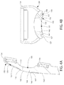
- FIGS. 4A and 4B illustrate the general contours and shapes of the island 140 and the passageway 133.
- the island 140 is formed by the annular wall 141 that protrudes from the floor 137 of the basin 136.
- the island 140 has an outer sidewall surface 147 that is spaced from the upstanding wall 138 that defines the periphery of the basin 136.
- the rear surface 146 of the island 140 which forms the free end of the island 140 as it extends from the floor 137 of the basin 136, is concave.
- the rear surface 146 of the island 140 extends further from the floor 137 of the basin 136 at the outer sidewall surface 147 than at an inner sidewall surface 148 that substantially surrounds and defines the passageway 133.
- the rear surface 146 of the island 140 angles inwardly towards the floor 137 of the basin 138 as it extends from the outer sidewall surface 147 to the inner sidewall surface 148.
- the passageway 133 is defined by the inner sidewall surface 148 of the island 140.
- the inner sidewall surface 148 of the island 140 converges as it extends from the rear surface 146 of the island 140 towards the front surface 131 of the base structure 130.
- the passageway 133 has a cross-sectional area that tapers from the rear surface 146 of the island 140 to the front surface 131 of the base structure 130.
- the invention is not to be so limited in all embodiments and in certain other embodiments the passageway 133 may have a constant cross-sectional area or a cross-sectional area that tapers from the front surface 131 of the base structure 140 to the rear surface 146 of the island 140.
- the oral care implement 100 comprises a carrier 160 having a front surface 161 and a rear surface 162.
- the carrier 160 comprises a plurality of tooth cleaning elements 163, which extend from the front surface 161 of the carrier 160.
- a portion of the carrier 160 is formed by a head plate and the tooth cleaning elements 163 are connected to the head plate via an anchor free tufting technique.
- the carrier 160 is not directly connected to the base structure 130 of the head 120. Rather, the carrier 160 is supported above the front surface 131 of the base structure 130 such that a gap 165 exists between the rear surface 162 of the carrier 160 and the front surface 131 of the base structure 130. As will be described in detail below, the carrier 160 is supported above the front surface 131 of the base structure 130 in a manner that enables the carrier 160 to be movable in various directions. Thus, the carrier 160 is movably supported above the front surface 131 of the base structure 130.
- the gap 165 forms a transverse passageway 166 from the first side surface 123 of the base structure 130 of the head 120 to the second side surface 124 of the base structure 130 of the head 120.
- the carrier 160 is positioned between the first pod 134 and the second pod 135 and is supported above the narrowed waist portion 122 of the base structure 130.
- one of the first or second pods 134, 135 may be omitted in other embodiments such that the carrier 160 is positioned adjacent to only one of the pods 134, 135 and supported thereby in a cantilever manner ( FIG. 8 ).
- the carrier 160 is supported above the first surface 131 of the base structure 130 by at least the first pod 134.
- the carrier 160 is supported above the first surface 131 of the base structure 130 by both the first and second pods 134, 135.
- the carrier 160 is supported above the front surface 131 of the base structure 140 by resilient connections 167 to each of the first and second pods 134, 135 such that the carrier 160 is movable relative to the head 120 and base structure 130 (and relative to the first and second pods 134, 135).
- the structure that facilitates the resilient connections 167 between the carrier 160 and each of the first and second pods 134, 135 will be described in more detail below with specific reference to FIGS. 6-7 .
- the first pod 134 comprises a plurality of tooth cleaning elements 105 extending therefrom and the second pod 135 comprises a plurality of tooth cleaning elements 106 extending therefrom. Attachment of the tooth cleaning elements 105, 106 to the first and second pods 134, 135 is achieved via an anchor free tufting technique and will be described in more detail below with reference to FIGS. 6-7 .
- the rear surface 131 of the base structure 130 comprises the basin 136 formed therein. Furthermore, in the exemplified embodiment the rear surface 130 of the base structure 130 comprises a resilient soft tissue cleanser 170.
- the soft tissue cleanser 170 comprises a pad portion 171 and a plurality of protuberances 172 protruding from the pad portion 171.
- the pad portion 171 of the soft tissue cleanser 170 is disposed in the basin 136 and an outer surface 174 of the pad portion 171 of the soft tissue cleanser 170 is flush with the rear surface 132 of the base structure 130 of the head 120.
- the tissue cleanser 170 forms a portion of the outer surface of the head 120 of the oral care implement 100.
- the pad portion 171 of the soft tissue cleanser 170 further includes an aperture 173 that surrounds the annular wall 141 that forms the island 140.
- the island 140 extends through the aperture 173 of the pad portion 171 of the soft tissue cleanser 170.
- the outer sidewall surface 147 of the island 140 is circumferentially surrounded by the resilient soft tissue cleanser 170.
- the resilient soft tissue cleanser 170 abuts against the outer sidewall surface 147 of the island 140, although the invention is not to be so limited in all embodiments and in certain other embodiments a space may exist between the resilient soft tissue cleanser 170 and the outer sidewall surface 147 of the island 140.
- the soft tissue cleanser 170 is separated and/or isolated from the passageway 133 by the island 140.
- the soft tissue cleanser 170 is formed into the basin 136 via an injection molding technique.
- each of the plurality of protuberances 172 is in the form of a nub.
- a nub generally refers to a column-like protrusion (without limitation to the cross-sectional shape of the protrusion) which is upstanding from a base surface.
- the protuberances 172 in the preferred construction have a height that is greater than the width at the base of the protuberance 172 (as measured in the longest direction).
- protuberances or nubs could include projections wherein the widths and heights are roughly the same or wherein the heights are somewhat smaller than the base widths.
- the base width can be substantially larger than the height.
- the plurality of protuberances 172 are conically shaped.
- conically shaped or “conical” is meant to include true cones, frusto-conically shaped elements, and other shapes that taper to a narrow end and thereby resemble a cone irrespective of whether they are uniform, continuous in their taper, or have rounded cross-sections.
- the soft tissue cleanser 170 including the pad 171 and the protuberances 172 are formed from a resilient material, such as an injection molded thermoplastic elastomer.
- the protuberances 172 of the soft tissue cleanser 170 can take the form of elongated ridges, nubs, or combinations thereof.
- the base structure 130 comprises a passageway 133 from the rear surface 132 of the base structure 130 (and more specifically from the rear surface 146 of the island 140) to the front surface 131 of the base structure 130.
- a mass 180 formed of a first resilient material is positioned within the passageway 133.
- a first portion 181 of the mass 180 protrudes from the front surface 131 of the base structure 130 of the head 120 and into the gap 165 between the rear surface 162 of the carrier 160 and the front surface 131 of the base structure 130.
- a second portion 182 of the mass 180 is visible from the rear surface 132 and also protrudes from the rear surface 132 of the base structure 130.
- the second portion 182 of the mass 180 doesn't protrude from the rear surface 132, but it is visible from the rear surface 132. In embodiments that comprise the island 140 on the rear surface 132 of the base structure 130, the second portion 182 of the mass 180 protrudes from the island 140. Furthermore, in certain embodiments the second portion 182 of the mass 180 also protrudes from a rear surface 108 of the head 120 that is formed by the outer surface 174 of the pad 171 of the soft tissue cleanser 170 from which the protuberances 172 protrude.
- the mass 180 comprises a first resilient material.
- the mass 180 is entirely formed from the resilient material.
- Suitable resilient materials for forming the mass 180 include injection molded thermoplastic elastomer or other rubber materials that are capable of resilient deformation and/or displacement.
- the invention is not to be so limited in all embodiments and the mass 180 can be formed of other resilient materials in certain other embodiments.
- the mass 180 is illustrated being formed entirely of the resilient material, in certain other embodiments the mass 180 may comprise a core that is formed of a rigid material, such as any of the hard plastic materials described herein, and a shell or overmold layer formed of the resilient material.
- the first portion 181 of the mass 180 can be formed of a resilient material while the second portion 182 of the mass 180 is formed of a rigid material.
- Other embodiments of the spheroid that achieve the functionality described below are contemplated.
- the mass 180 is not limited to being formed entirely of a resilient material in all embodiments.
- the mass 180 is illustrated being substantially spherical in shape.
- the invention is not to be so limited in all embodiments and in certain other embodiments the mass 180 may take on other spheroid-type shapes, such as for example without limitation an oblate spheroid, a prolate spheroid, an ellipsoid, an ovoid or any par- or truncated versions thereof.
- shapes other than those exemplified are contemplated for the mass 180 of the present invention and the mass 180 is not to be particularly limited by its shape in all embodiments unless so specified in the claims.
- the mass 180 has a first portion 181 that protrudes from the front surface 131 of the base structure 130 into the gap 165 and a second portion 182 that protrudes from the rear surface 132 of the base structure 130, and more specifically from the rear surface 146 of the island 140. Furthermore, the first portion 181 of the mass 180 comprises a first domed surface and the second portion 182 of the mass 180 comprises a second domed surface. Thus, each of the first and second portions 181, 182 of the mass 180 protrude from their respective surfaces so as to form a dome-shaped surface.
- the first portion 181 of the mass 180 that protrudes from the front surface 131 of the base structure 130 and into the gap 165 is in surface contact with the rear surface 162 of the carrier 160.
- the invention is not to be so limited in all embodiments and in certain other embodiments the first portion 181 of the mass 180 may protrude into the gap 165 without contacting the rear surface 161 of the carrier 160.
- the mass 180 alters movement of the carrier 160 relative to the base structure 130 of the head 120 through surface contact with the rear surface 162 of the carrier 160. Specifically, due to being formed at least partially of a resilient material, the mass 180 is deformable and/or displaceable within the passageway 133 and/or within the gap 165. Thus, during brushing as brushing forces are applied to the plurality of tooth cleaning elements 163 extending from the carrier 160, the carrier 160 translates downwardly in a direction toward the front surface 131 of the base structure 130 by such deformation and/or displacement of the mass 180 relative to the base structure 130.
- the resilient connection 167 between the carrier 160 and the first and/or second pods 134, 135 facilitates such translational movement of the carrier 160 in response to a brushing force being applied to the carrier 160 in the direction of the front surface 131 of the base structure 130.
- the force imparted onto the carrier 160 during brushing is sufficient to deform or displace the mass 180 to create such a translational movement of the carrier 160 relative to the base structure 130.
- the mass 180 acts as a pivot on which the carrier 160 can move.
- the carrier 160 can pivot with respect to the base structure 130 about the first portion 181 of the mass 180.
- the direction of pivot of the carrier 160 is in a side-to-side direction transverse to the longitudinal axis A-A.
- the resilient connection 167 between the carrier 160 and the first and/or second pods 134, 135 also facilitates the pivoting and translational movements of the carrier 160 relative to the base structure 130.
- the carrier 160 is supported above the front surface 131 of the base structure 130 so as to be positioned above the narrowed waist portion 122 of the base structure 130.
- the narrowed waist portion 122 of the base structure 130 increases the permissible degree of the pivoting motion of the carrier 160. If the narrowed waist portion 122 were omitted and the first and second sidewalls 123, 124 of the base structure 130 below the carrier 160 were not narrowed as described herein, side-to-side movement of the carrier 160 relative to the base structure 130 would be restricted because the carrier 160 would come into contact with the first and second sidewalls 123, 124 during such pivoting. By narrowing the sidewalls 123, 124 in the base structure 130 in a location that is below the carrier 160, side-to-side pivoting motion of the carrier 160 is less restricted than it would otherwise be.
- both the soft tissue cleanser 170 and the mass 180 are formed into or connected to the head 120 via an injection molding step.
- the soft tissue cleanser 170 is separated or isolated from the passageway 133 by the island 140, and more specifically by the outer sidewall surface 147 of the island 140.
- the mass 180 is positioned within the passageway 133.
- the soft tissue cleanser 170 is also isolated from the mass 180 by the island 140 (and specifically by the annular wall 141 of the island 140).
- the mass 180 and the soft tissue cleanser 170 are both formed from an injection molding technique, each is made from a separate injection molding shot.
- the mass 180 and soft tissue cleanser 170 are not unitary or integral, but rather are separate components that are both isolated from one another and separately formed from one another. Furthermore, the soft tissue cleanser 170 and the mass 180 may be formed of different materials, such that the mass 180 has a greater Shore durometer (e.g., Shore A hardness value) than the soft tissue cleanser 170 or vice versa.
- the mass 180 is formed of or comprises a first resilient material and the soft tissue cleanser 170 is formed of or comprises a second resilient material.
- the second resilient material is the same as the first resilient material and in other embodiments the second resilient material is different from the first resilient material.
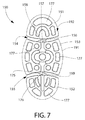
- the head plate 150 is used for mounting the tooth cleaning elements via an anchor free tufting technique.
- the head plate 150 is secured to the base structure 130 of the head 120 such as by ultrasonic welding.
- the head plate 150 can be secured to the base structure 130 of the head 120 by techniques other than ultrasonic welding, such as for example without limitation thermal welding, a tight-fit assembly, a coupling sleeve, threaded engagement, adhesion, fasteners, a snap-fit or the like.
- the unitary head plate 150 generally comprises a first end portion 151, a second end portion 152 and a middle portion 153.
- a first transverse channel 154 extends between the first end portion 151 and the middle portion 153 forming a gap therebetween.
- a second transverse channel 155 extends between the second end portion 152 and the middle portion 153 forming a gap therebetween.
- a first strut 156 extends longitudinally through the first transverse channel 154 from a proximal end 157 of the first end portion 151 to a distal end 158 of the middle portion 153 to connect the first end portion 151 to the middle portion 153.
- a second strut 159 extends longitudinally through the second transverse channel 155 from a proximal end 175 of the middle portion 153 to a distal end 176 of the second end portion 152 to connect the second end portion 152 to the middle portion 153.
- the first and second struts 156, 159 maintain the head plate 150 as a unitary structure that is integrally formed as a single unit despite the gaps formed by the first and second transverse channels 154, 155.
- the unitary head plate 150 is coupled to the first and second pods 134, 135 so that the first end portion 151 of the head plate 150 forms a portion of the first pod 134 and the second end portion 152 of the head plate 150 forms a portion of the second pod 135. Furthermore, the middle portion 153 of the head plate 150 forms at least a portion of the carrier 160. In certain embodiments, the middle portion 153 of the head plate 150 forms the entirety of the carrier 160. Thus, the first end portion 151 of the head plate 150 is directly connected to the first pod 134 and the second end portion 152 of the head plate 150 is directly connected to the second pod 135.
- the middle portion 153 is not directly connected to either the first or second pod 134, 135 or any other portion of the base structure 130, but rather the middle portion 153 is movably and/or flexibly supported above the base structure 130 by the first and second pods 134, 135 (and by the first and second end portions 151, 152 of the head plate 150) as has been described above.
- the first and second transverse channels 154, 155 are filled with a resilient material 189.
- the resilient material 189 is omitted from FIG. 7 so that the first and second struts 156, 159 are visible.
- the resilient connections between the carrier 160 and the first and second pods 134, 135 described above are formed by a combination of the resilient material 189 that fills in the first and second transverse channels 154, 155 and the first and second struts 156, 159.
- the middle portion 153 of the head plate 150 is capable of flexing up-and-down and side-to-side relative to the first and second end portions 151, 152.
- the resilient material 189 and the first and second struts 156, 159 facilitate the movement of the carrier 160 relative to the base structure 130 (and relative to the first and second pods 134, 135) as has been described herein in detail above.
- the unitary head plate 150 comprises a plurality of openings 177 extending from a front surface 178 of the head plate 150 to a rear surface 179 of the head plate 150 (only a select few of the openings 177 are labeled in FIG. 7 to avoid clutter).
- the tooth cleaning elements 105, 106, 163 are positioned within the openings 177 so that a distal end of the tooth cleaning elements 105, 106, 163 protrudes through a rear surface 191 of the head plate 150 and a major portion of the tooth cleaning elements 105, 106, 163 extends from the front surface 192 of the head plate 150.
- the portions of the tooth cleaning elements 105, 106, 163 that extend from the front surface 192 of the head plate 150 are used to engage the user's teeth and oral surfaces during use of the oral care implement 100.
- the tooth cleaning elements 105, 106, 163 are connected to the head plate 150 via an anchor free tufting technique.
- the distal ends of the tooth cleaning elements 105 of the first pod 134 are melted together by heat to be anchored in place and to form a first melt mat 193.
- the distal ends of the tooth cleaning elements 106 of the second pod 135 are similarly melted together by heat to be anchored in place and to form a second melt mat 194.
- the distal ends of the tooth cleaning elements 163 of the carrier 160 are melted together by heat to be anchored in place and to form a third melt mat 195.
- the tooth cleaning elements 105, 106, 163 are illustrated as bristles.
- Common examples of tooth cleaning elements include, without limitation, bristle tufts, filament bristles, fiber bristles, nylon bristles, spiral bristles, rubber bristles, elastomeric protrusions, flexible polymer protrusions, combinations thereof and/or structures containing such materials or combinations.
- the tooth cleaning elements may include all bristles, a combination of bristles and elastomeric elements, or all elastomeric elements. Suitable elastomeric materials include any biocompatible resilient material suitable for uses in an oral hygiene apparatus.
- the elastomeric material of any tooth or soft tissue engaging elements has a hardness property in the range of A8 to A25 Shore hardness.
- One suitable elastomeric material is styrene-ethylene/butylene-styrene block copolymer (SEBS) manufactured by GLS Corporation. Nevertheless, SEBS material from other manufacturers or other materials within and outside the noted hardness range could be used.
- an oral care implement 200 in accordance with a second embodiment of the present invention will be described.
- only components of the oral care implement 200 that are different from the oral care implement 100 will be described herein.
- similar components will be similarly numbered except that the 200-series of numbers will be used.
- the oral care implement 200 generally comprises a handle 210 and a head 220.
- the handle 210 is generically illustrated and can take on any shape, contour or general appearance as desired.
- the head 220 is connected to the handle 210, and in certain embodiments may be integrally formed with the handle 210.
- the head 220 and the handle 210 are formed of a rigid material, such as one of the hard plastic materials discussed herein above.
- the head 210 comprises a carrier 260 having a front surface 261 and an opposed rear surface 262.
- a plurality of tooth cleaning elements 263 extend outwardly from the front surface 261 of the carrier 260.
- the head 210 comprises a base structure 230 having a front surface 231 and an opposed rear surface 232.
- the oral care implement 200 further comprises a first pod 234 extending upwardly from the front surface 231 of the base structure 230 of the head 220.
- the carrier 260 is movably supported above the front surface 231 of the base structure 230 by the first pod 234.
- the carrier 260 is supported above the front surface 231 of the base structure 230 by the first pod 234 in a cantilevered manner. Due to the support of the carrier 260 by the first pod 234, a gap 265 is formed between the rear surface 262 of the carrier 260 and the front surface 231 of the base structure 230.
- the first pod 234 is merely an upstanding wall that extends upwardly from the front surface 231 of the base structure 230. In this manner, the first pod 234 acts as a living hinge that enables the carrier 260 to flex downwardly into the gap 265 in the direction of the base surface 230 in response to a force (i.e., a brushing force) acting on the carrier 260.
- a force i.e., a brushing force
- the invention is not to be limited to the particular structural arrangement of the first pod 234 in all embodiments and in certain other embodiments the first pod 234 can merely be a hinge, a wall or a protuberance having any shape or configuration that is capable of supporting the carrier 260 in a cantilevered manner as illustrated.
- connection between the first pod 234 and the carrier 260 is a rigid connection and the first pod 234 and carrier 260 appear to be integrally formed.
- the invention is not to be so limited and the first pod 234 and carrier 260 can be resiliently connected such that a resilient material extends between the first pod 234 and the carrier 260 to achieve the connection between the first pod 234 and the carrier 260 as has been described above with regard to the oral care implement 100.
- the base structure 230 comprises an opening 233 that forms a passageway from the front surface 231 of the base structure 230 to the rear surface 232 of the base structure 230.
- a mass 280 formed of a resilient material which may be in the shape of a sphere or otherwise as has been discussed herein above with regard to the mass 180 of the oral care implement 100, is disposed within the opening 233 so that a first portion 281 of the mass 280 protrudes from the front surface 231 of the base structure 230 and a second portion 282 of the mass 280 protrudes from the rear surface 232 of the base structure 230.
- the mass 280 is formed of any of the materials that have been described above for the mass 180.
- the mass 280 is capable of deformation or displacement in response to a brushing force. Therefore, during brushing, when a normal brushing force is applied to the tooth cleaning elements 263 of the carrier 260, the carrier 260 is translatable toward the front surface 231 of the base structure 230 via the deformation and/or displacement of the mass 280 relative to the base structure 230.
- the carrier 260 can also pivot with respect to the base structure 230 about the first portion 281 of the mass 280 when a normal brushing force is applied to the carrier 260.
- ranges are used as shorthand for describing each and every value that is within the range. Any value within the range can be selected as the terminus of the range. In the event of a conflict in a definition in the present disclosure and that of a cited reference, the present disclosure controls.
Description
- The present invention relates generally to oral care implements, such as toothbrushes.
- A variety of toothbrush head configurations exist that have manually and/or mechanically-driven movable cleaning elements. Many of these configurations include cleaning elements that extend from a rigid head. Teeth and gums by nature have a complex intricate contour. Due to the rigid nature of the attachment of the cleaning elements to the head of the toothbrush, the orientation of the cleaning elements is not flexible.
-
WO2009/157932 discloses an oral care implement comprising a head having a carrier with a passageway formed therethrough. An oral care material store is located in the passageway.US 7,143,462 discloses an oral care implement which includes a handle and a head with a soft tissue cleaner on the back side thereof. The back side of the head includes peg members which form anchor points for the soft tissue cleaner. -
US 2011/0308026 A1 discloses an oral care device having a head connected to a handle, the head comprising a base structure having a front surface and a rear surface, and a carrier with a front surface and a rear surface, and a plurality of teeth cleaning elements extending from the front surface of the carrier, the carrier being movably supported above the front surface of the base structure by a protuberance so that a gap exists between the rear surface of the carrier and the front surface of the base structure. - The present invention provides an oral care implement according to claim 1.
- Optional features are recited in the dependent claims.
- Further areas of applicability of the present invention will become apparent from the detailed description provided hereinafter. It should be understood that the detailed description and specific examples, while indicating the preferred embodiment of the invention, are intended for purposes of illustration only and are not intended to limit the scope of the invention.
- The present invention will become more fully understood from the detailed description and the accompanying drawings, wherein:
-
Figure 1 is a front perspective view of an oral care implement in accordance with a first embodiment of the present invention; -
Figure 2 is a rear perspective view of the oral care implement ofFIG. 1 ; -
Figure 3A is a front perspective view of the base structure of the head of the oral care implement ofFIG. 1 ; -
Figure 3B is a rear perspective view of the base structure of the head of the oral care implement ofFIG. 1 ; -
Figure 3C is a rear view of the base structure of the head of the oral care implement ofFIG. 1 ; -
Figure 4A is a cross-sectional view taken along line IVA-IVA ofFIG. 3B ; -
Figure 4B is a cross-sectional view taken along line IVB-IVB ofFIG. 3B ; -
Figure 5 is a side view of the oral care implement ofFIG. 1 ; -
Figure 5A is a close-up view of area V-A ofFIG. 5 ; -
Figure 6 is a cross-sectional view taken along line VI-VI ofFIG. 1 ; -
Figure 6A is a close-up view of area VI-A ofFIG. 6 ; and -
Figure 7 is a front view of the head plate of the oral care implement ofFIG. 1 with the resilient material omitted; and -
Figure 8 is a longitudinal cross-sectional view of an oral care implement in accordance with a second embodiment of the present invention. - The following description of the preferred embodiment(s) is merely exemplary in nature and is in no way intended to limit the invention, its application, or uses.
- The description of illustrative embodiments according to principles of the present invention is intended to be read in connection with the accompanying drawings, which are to be considered part of the entire written description. In the description of the exemplary embodiments of the invention disclosed herein, any reference to direction or orientation is merely intended for convenience of description and is not intended in any way to limit the scope of the present invention. Relative terms such as "lower," "upper," "horizontal," "vertical," "above," "below," "up," "down," "left," "right," "top," "bottom," "front" and "rear" as well as derivatives thereof (e.g., "horizontally," "downwardly," "upwardly," etc.) should be construed to refer to the orientation as then described or as shown in the drawing under discussion. These relative terms are for convenience of description only and do not require that the apparatus be constructed or operated in a particular orientation unless explicitly indicated as such. Terms such as "attached," "affixed," "connected," "coupled," "interconnected," "secured" and similar refer to a relationship wherein structures are secured or attached to one another either directly or indirectly through intervening structures, as well as both movable or rigid attachments or relationships, unless expressly described otherwise. Moreover, the features and benefits of the invention are described by reference to the exemplary embodiments illustrated herein. Accordingly, the invention expressly should not be limited to such exemplary embodiments, even if indicated as being preferred. The discussion herein describes and illustrates some possible non-limiting combinations of features that may exist alone or in other combinations of features. The scope of the invention is defined by the claims appended hereto.
- Referring first to
FIGS. 1 and 2 concurrently, an oral care implement 100 in accordance with an embodiment of the present invention will be described. In the exemplified embodiment, theoral care implement 100 is in the form of a manual toothbrush. However, in certain other embodiments theoral care implement 100 can take on other forms such as being a powered toothbrush, a tongue scraper, a gum and soft tissue cleaner, a water pick, an interdental device, a tooth polisher, a specially designed ansate implement having tooth engaging elements or any other type of implement that is commonly used for oral care. Thus, it is to be understood that the inventive concepts discussed herein can be applied to any type of oral care implement unless a specific type of oral care implement is specified in the claims. - The oral care implement 100 extends along a longitudinal axis A-A from a
proximal end 101 to adistal end 102. Theoral care implement 100 generally comprises ahandle 110 and ahead 120. Thehandle 110 is an elongated structure that provides the mechanism by which the user can hold and manipulate the oral care implement 100 during use. Thehandle 110 can take on a wide variety of shapes, contours and configurations, none of which are limiting of the present invention. In the exemplified embodiment, thehandle 110 is formed of a rigid material, such as a hard plastic material. The hard plastic material that can be used to form thehandle 110 includes, for example without limitation, polypropylene, polymers and copolymers of ethylene, propylene, butadiene, vinyl compounds and polyesters such as polyethylene terephthalate. Of course, the invention is not to be so limited in all embodiments and thehandle 110 may be formed with a resilient material, such as a thermoplastic elastomer, over portions of or the entirety of thehandle 110 to enhance the gripability of thehandle 110 during use. In the exemplified embodiment, thehandle 110 comprises aresilient material 103 in the thumb grip region. Thus, theresilient material 103 is in the region of thehandle 110 that will be gripped by a user's thumb and forefinger during use of the oral care implement 100. - The
head 120 is coupled to adistal end 109 of thehandle 110. In the exemplified embodiment, thehead 120 and thehandle 110 are integrally formed as a single unitary structure using a molding, milling, machining or other suitable process. However, in other embodiments thehandle 110 and thehead 120 may be formed as separate components which are operably connected at a later stage of the manufacturing process by any suitable technique known in the art, including without limitation thermal or ultrasonic welding, a tight-fit assembly, a coupling sleeve, threaded engagement, adhesion, or fasteners. Whether thehead 120 and thehandle 110 are of a unitary or multi-piece construction (including connection techniques) is not limiting of the present invention unless specifically claimed. In some embodiments of the invention, thehead 120 may be detachable (and replaceable) from thehandle 110 using techniques known in the art. - Referring to
FIGS. 3A-3C concurrently, thehead 120 will be described in more detail. Thehead 120 of the oral care implement 100 generally comprises abase structure 130 having afront surface 131, an opposingrear surface 132 and apassageway 133 extending through thebase structure 130 from thefront surface 131 to therear surface 132. In certain other embodiments, thepassageway 133 may not extend entirely through thebase structure 130 and may merely form an opening in thefront surface 131 of thebase structure 130 such that the opening forms a socket in thefront surface 131 of thebase structure 130 rather than a passageway through thebase structure 130. In still other embodiments thepassageway 133 may merely form an opening in therear surface 132 of thebase structure 130 such that the opening forms a socket in therear surface 132 of thebase structure 130 rather than a passageway through thebase structure 130. - The
base structure 130 comprises aproximal portion 196, adistal portion 197 and a narrowedwaist portion 122 longitudinally positioned in between the proximal anddistal portions waist portion 122, thebase structure 130 is in the general shape of an hourglass in that it is wider at the top and bottom and narrower in the middle. In the exemplified embodiment, thebase structure 130 comprises afirst pod 134 extending from thefront surface 131 of thebase structure 130 at thedistal portion 197 of the base structure 130 (which is also thedistal end 102 of the oral care implement 100) and asecond pod 135 extending from thefront surface 131 of thebase structure 130 at theproximal portion 196 of thebase structure 130. The termsfirst pod 134 andsecond pod 135, as used herein, differentiate between different pods of the oral care implement 100 without any specific location on the head being implied. Thus, in certain embodiments thefirst pod 134 can be positioned at theproximal portion 196 of thebase structure 130 and thesecond pod 135 can be positioned at thedistal portion 197 of thebase structure 130. - Moreover, although the components extending from the
front surface 131 of thebase structure 130 at the proximal anddistal portions base structure 130 are referred to herein as first andsecond pods second pods front surface 131 of thebase structure 130, such as an upstanding wall, a hinge, a strut or the like. In such embodiments, thefirst pod 134 may be referred to herein as a first protuberance and thesecond pod 135 may be referred to herein as a second protuberance. The first andsecond pods front surface 131 of thebase structure 130. Furthermore, although the invention is illustrated and described herein as having thefirst pod 134 and thesecond pod 135, in certain embodiments the invention may comprise only one of the pods or only a single protuberance extending upwardly from thefront surface 131 of thebase structure 130. - The
base structure 130 comprises a generally U-shaped cross-section extending longitudinally from thefirst pod 134 to thesecond pod 135. The U-shaped cross-section is formed by the first andsecond pods front surface 131 of thebase structure 130 at the proximal anddistal portions base structure 130, respectively. The portion of thebase structure 130 that is longitudinally positioned in between the first andsecond pods 134, 135 (i.e., the narrowed waist portion 122) does not have any component extending upward from thefront surface 131 of thebase structure 130, and thereby forms the bottom curved portion of the U-shape of thebase structure 130. This shape of thebase structure 130 facilitates movably mounting cleaning elements to thebase structure 130 as will be described in more detail below. - Each of the first and
second pods base structure 130. Furthermore, thebase structure 130 is formed from a rigid material such as a hard plastic (i.e., any of the hard plastic materials listed above with regard to the handle 110). Due to the integral formation of the first andsecond pods base structure 130, each of the first andsecond pods base structure 130. Thus, although there is inherent flexibility in all materials, the first andsecond pods base structure 130 due to their hard plastic material and integral formation. - The
base structure 130 of thehead 120 of the oral care implement 100 comprises aperipheral sidewall 121 that extends between the front andrear surfaces base structure 130. Theperipheral sidewall 121 forms the periphery of thebase structure 130. Theperipheral sidewall 121 includes afirst side wall 123 and an opposingsecond side wall 124. Each of the first andsecond side walls peripheral sidewall 121 is contoured so as to form the periphery of the proximal anddistal portions waist portion 122 and to give thebase structure 130 the hourglass shape noted above. - The
first side wall 123 forms a first concave edge in the region of thewaist portion 122 of thebase structure 130 and thesecond side wall 124 forms a second concave edge in the region of thewaist portion 122 of the base structure. Thus, thewaist portion 122 is a narrowed portion of thebase structure 130 positioned longitudinally between the proximal anddistal portions second pods 134, 135). Of course, the invention is not to be particularly limited by the contours and shapes of thebase structure 130 in all embodiments unless so specified in the claims. - As noted above, the
base structure 130 extends from theproximal portion 196 to thedistal portion 197. Thebase structure 130 has a first width W1 at the widest point of theproximal portion 196 and a second width W2 at the widest point of thedistal portion 197. In the exemplified embodiment, the first width W1 is substantially the same as the second width W2. However, the invention is not to be so limited in all embodiments and in certain other embodiments the first width W1 can be greater than the second width W2 or vice versa. - The width of the
base structure 130 gradually decreases as thebase structure 130 extends from theproximal portion 196 to a longitudinal center C of thebase portion 130. The width of thebase structure 130 then gradually increases as thebase structure 130 extends from the longitudinal center C to thedistal portion 197. As a result of the gradual increasing and decreasing of the width from theproximal portion 196 to thedistal portion 197, the narrowedwaist portion 122 of thebase structure 130 has a varied width. Furthermore, each of the first andsecond side walls waist portion 122 - (i.e., between the proximal and
distal portions waist portion 122 has a third width W3 at the longitudinal center C. The third width W3 is less than each of the first and second widths W1, W2 and is the narrowest portion of the narrowedwaist portion 122 of thebase structure 130. In certain embodiments, the third width W3 is between 60% and 80% of the first and second widths W1, W2, and more specifically between 65% and 80% of the first and second widths W1, W2. - Although the
base structure 130 is described herein as having its narrowest portion at the longitudinal center C of thebase structure 130, the longitudinal center C is not the actual center of thebase structure 130 in all embodiments. Rather, the longitudinal center C is the point on thebase structure 130 that is the narrowest within the narrowedwaist portion 122. Thus, although the narrowedwaist portion 122 of thebase structure 130 is positioned longitudinally between the proximal anddistal portions base structure 130, the narrowedwaist portion 122 is not centered longitudinally along thebase structure 130 in all embodiments. - The
rear surface 132 of thebase structure 130 comprises abasin 136 having afloor 137. In certain embodiments, thefloor 137 can be conceptually considered as a part of therear surface 132 of thebase structure 130. Thebasin 136 is defined by anupstanding wall 138 that extends upwardly from thefloor 137 and surrounds thebasin 136. Theupstanding wall 138 forms a peripheral sidewall of thebasin 138. - The
base structure 130 further comprises anisland 140 extending from thefloor 137 of thebasin 136. Theisland 140 is formed by anannular wall 141 extending upwardly from thefloor 137 of thebasin 136. Theisland 140, and more specifically theannular wall 141 of theisland 140, comprises anouter sidewall surface 147 extending upwardly from thefloor 137 of thebasin 136. In the exemplified embodiment, theisland 140 is located in the narrowedwaist portion 122 of thebase structure 130. Furthermore, thepassageway 133 is located within theisland 140, and specifically extends through thebase structure 130 from thefront surface 131 of thebase structure 130 to arear surface 146 of theisland 140. Thus, theisland 140 is an annular, ring-like structure with thepassageway 133 centrally formed into theisland 140. The invention is not to be limited to theisland 140 being located in the narrowedwaist portion 122 of thebase structure 130 in all embodiments and in certain other embodiments the location of theisland 140, and hence also thepassageway 133, can be modified. - As noted above, in the exemplified embodiment the
base structure 130 of thehead 120 is formed integrally with thehandle 110. Furthermore, theisland 140 is also integrally formed with thebase structure 130. Thus, in the exemplified embodiment the base structure 130 (including the island 140) and thehandle 110 are a single, unitary component formed of a rigid plastic material, such as polymers and copolymers of ethylene, propylene, butadiene, vinyl compounds and polyesters such as polyethylene terephthalate. The preferred material for thehandle 110 is polypropylene. However, as noted above in other embodiments thehead 120, and hence thebase structure 130 andisland 140, can be separately formed from thehandle 110 and later attached thereto. However, regardless of whether thebase structure 130 and handle 110 are integrally or separately formed, theisland 140 forms a part of and is integrally formed with thebase structure 130. - Referring to
FIGS. 4A and 4B concurrently, the oral care implement 100 will be described in more detail.FIGS. 4A and 4B illustrate the general contours and shapes of theisland 140 and thepassageway 133. As can be seen, theisland 140 is formed by theannular wall 141 that protrudes from thefloor 137 of thebasin 136. Theisland 140 has anouter sidewall surface 147 that is spaced from theupstanding wall 138 that defines the periphery of thebasin 136. - In the exemplified embodiment, the
rear surface 146 of theisland 140, which forms the free end of theisland 140 as it extends from thefloor 137 of thebasin 136, is concave. Thus, therear surface 146 of theisland 140 extends further from thefloor 137 of thebasin 136 at theouter sidewall surface 147 than at aninner sidewall surface 148 that substantially surrounds and defines thepassageway 133. Thus, therear surface 146 of theisland 140 angles inwardly towards thefloor 137 of thebasin 138 as it extends from theouter sidewall surface 147 to theinner sidewall surface 148. - As noted above, the
passageway 133 is defined by theinner sidewall surface 148 of theisland 140. In the exemplified embodiment, theinner sidewall surface 148 of theisland 140 converges as it extends from therear surface 146 of theisland 140 towards thefront surface 131 of thebase structure 130. Thus, thepassageway 133 has a cross-sectional area that tapers from therear surface 146 of theisland 140 to thefront surface 131 of thebase structure 130. Of course, the invention is not to be so limited in all embodiments and in certain other embodiments thepassageway 133 may have a constant cross-sectional area or a cross-sectional area that tapers from thefront surface 131 of thebase structure 140 to therear surface 146 of theisland 140. - Referring to
FIGS. 5-6A concurrently, the oral care implement will be further described. The oral care implement 100 comprises acarrier 160 having afront surface 161 and arear surface 162. Thecarrier 160 comprises a plurality oftooth cleaning elements 163, which extend from thefront surface 161 of thecarrier 160. As will be described in more detail below, in certain embodiments a portion of thecarrier 160 is formed by a head plate and thetooth cleaning elements 163 are connected to the head plate via an anchor free tufting technique. - The
carrier 160 is not directly connected to thebase structure 130 of thehead 120. Rather, thecarrier 160 is supported above thefront surface 131 of thebase structure 130 such that agap 165 exists between therear surface 162 of thecarrier 160 and thefront surface 131 of thebase structure 130. As will be described in detail below, thecarrier 160 is supported above thefront surface 131 of thebase structure 130 in a manner that enables thecarrier 160 to be movable in various directions. Thus, thecarrier 160 is movably supported above thefront surface 131 of thebase structure 130. Thegap 165 forms atransverse passageway 166 from thefirst side surface 123 of thebase structure 130 of thehead 120 to thesecond side surface 124 of thebase structure 130 of thehead 120. - In the exemplified embodiment, the
carrier 160 is positioned between thefirst pod 134 and thesecond pod 135 and is supported above the narrowedwaist portion 122 of thebase structure 130. However, as noted above one of the first orsecond pods carrier 160 is positioned adjacent to only one of thepods FIG. 8 ). Regardless, thecarrier 160 is supported above thefirst surface 131 of thebase structure 130 by at least thefirst pod 134. In the exemplified embodiment, thecarrier 160 is supported above thefirst surface 131 of thebase structure 130 by both the first andsecond pods carrier 160 is supported above thefront surface 131 of thebase structure 140 byresilient connections 167 to each of the first andsecond pods carrier 160 is movable relative to thehead 120 and base structure 130 (and relative to the first andsecond pods 134, 135). The structure that facilitates theresilient connections 167 between thecarrier 160 and each of the first andsecond pods FIGS. 6-7 . - In addition to the
carrier 160 comprisingtooth cleaning elements 163 extending therefrom, thefirst pod 134 comprises a plurality oftooth cleaning elements 105 extending therefrom and thesecond pod 135 comprises a plurality oftooth cleaning elements 106 extending therefrom. Attachment of thetooth cleaning elements second pods FIGS. 6-7 . - As discussed above, the
rear surface 131 of thebase structure 130 comprises thebasin 136 formed therein. Furthermore, in the exemplified embodiment therear surface 130 of thebase structure 130 comprises a resilientsoft tissue cleanser 170. Thesoft tissue cleanser 170 comprises apad portion 171 and a plurality ofprotuberances 172 protruding from thepad portion 171. Thepad portion 171 of thesoft tissue cleanser 170 is disposed in thebasin 136 and anouter surface 174 of thepad portion 171 of thesoft tissue cleanser 170 is flush with therear surface 132 of thebase structure 130 of thehead 120. Thus, thetissue cleanser 170 forms a portion of the outer surface of thehead 120 of the oral care implement 100. Thepad portion 171 of thesoft tissue cleanser 170 further includes anaperture 173 that surrounds theannular wall 141 that forms theisland 140. Thus, theisland 140 extends through theaperture 173 of thepad portion 171 of thesoft tissue cleanser 170. - The
outer sidewall surface 147 of theisland 140 is circumferentially surrounded by the resilientsoft tissue cleanser 170. In certain embodiments, the resilientsoft tissue cleanser 170 abuts against theouter sidewall surface 147 of theisland 140, although the invention is not to be so limited in all embodiments and in certain other embodiments a space may exist between the resilientsoft tissue cleanser 170 and theouter sidewall surface 147 of theisland 140. Thus, thesoft tissue cleanser 170 is separated and/or isolated from thepassageway 133 by theisland 140. In certain embodiments, thesoft tissue cleanser 170 is formed into thebasin 136 via an injection molding technique. - In the exemplified embodiment, each of the plurality of
protuberances 172 is in the form of a nub. As used herein a "nub" generally refers to a column-like protrusion (without limitation to the cross-sectional shape of the protrusion) which is upstanding from a base surface. In a general sense, theprotuberances 172 in the preferred construction have a height that is greater than the width at the base of the protuberance 172 (as measured in the longest direction). Nevertheless, protuberances or nubs could include projections wherein the widths and heights are roughly the same or wherein the heights are somewhat smaller than the base widths. Moreover, in some circumstances (e.g., where the protuberances tapers to a tip or includes a base portion that narrows to a smaller projection), the base width can be substantially larger than the height. - In one preferred arrangement of the
soft tissue cleanser 170, the plurality ofprotuberances 172 are conically shaped. As used herein, "conically shaped" or "conical" is meant to include true cones, frusto-conically shaped elements, and other shapes that taper to a narrow end and thereby resemble a cone irrespective of whether they are uniform, continuous in their taper, or have rounded cross-sections. In the exemplified embodiment, thesoft tissue cleanser 170 including thepad 171 and theprotuberances 172 are formed from a resilient material, such as an injection molded thermoplastic elastomer. An example of a suitable elastomeric soft tissue cleaner that may be used with the present invention and positioned on therear surface 131 of thebase structure 130 of thehead 120 is disclosed inU.S. Patent No. 7,143,462, issued December 5, 2006 to the assignee of the present application. In certain other embodiments, theprotuberances 172 of thesoft tissue cleanser 170 can take the form of elongated ridges, nubs, or combinations thereof. - Still referring to
FIGS. 5-6A , as discussed above thebase structure 130 comprises apassageway 133 from therear surface 132 of the base structure 130 (and more specifically from therear surface 146 of the island 140) to thefront surface 131 of thebase structure 130. In the exemplified embodiment, amass 180 formed of a first resilient material is positioned within thepassageway 133. Afirst portion 181 of themass 180 protrudes from thefront surface 131 of thebase structure 130 of thehead 120 and into thegap 165 between therear surface 162 of thecarrier 160 and thefront surface 131 of thebase structure 130. Asecond portion 182 of themass 180 is visible from therear surface 132 and also protrudes from therear surface 132 of thebase structure 130. In some embodiments, thesecond portion 182 of themass 180 doesn't protrude from therear surface 132, but it is visible from therear surface 132. In embodiments that comprise theisland 140 on therear surface 132 of thebase structure 130, thesecond portion 182 of themass 180 protrudes from theisland 140. Furthermore, in certain embodiments thesecond portion 182 of themass 180 also protrudes from arear surface 108 of thehead 120 that is formed by theouter surface 174 of thepad 171 of thesoft tissue cleanser 170 from which theprotuberances 172 protrude. - As noted above, the
mass 180 comprises a first resilient material. In the exemplified embodiment, themass 180 is entirely formed from the resilient material. Suitable resilient materials for forming themass 180 include injection molded thermoplastic elastomer or other rubber materials that are capable of resilient deformation and/or displacement. However, the invention is not to be so limited in all embodiments and themass 180 can be formed of other resilient materials in certain other embodiments. Furthermore, although themass 180 is illustrated being formed entirely of the resilient material, in certain other embodiments themass 180 may comprise a core that is formed of a rigid material, such as any of the hard plastic materials described herein, and a shell or overmold layer formed of the resilient material. In still other embodiments, thefirst portion 181 of themass 180 can be formed of a resilient material while thesecond portion 182 of themass 180 is formed of a rigid material. Other embodiments of the spheroid that achieve the functionality described below are contemplated. Thus, themass 180 is not limited to being formed entirely of a resilient material in all embodiments. - Furthermore, in the exemplified embodiment the
mass 180 is illustrated being substantially spherical in shape. However, the invention is not to be so limited in all embodiments and in certain other embodiments themass 180 may take on other spheroid-type shapes, such as for example without limitation an oblate spheroid, a prolate spheroid, an ellipsoid, an ovoid or any par- or truncated versions thereof. Thus, shapes other than those exemplified are contemplated for themass 180 of the present invention and themass 180 is not to be particularly limited by its shape in all embodiments unless so specified in the claims. - As noted above, the
mass 180 has afirst portion 181 that protrudes from thefront surface 131 of thebase structure 130 into thegap 165 and asecond portion 182 that protrudes from therear surface 132 of thebase structure 130, and more specifically from therear surface 146 of theisland 140. Furthermore, thefirst portion 181 of themass 180 comprises a first domed surface and thesecond portion 182 of themass 180 comprises a second domed surface. Thus, each of the first andsecond portions mass 180 protrude from their respective surfaces so as to form a dome-shaped surface. - In the exemplified embodiment, the
first portion 181 of themass 180 that protrudes from thefront surface 131 of thebase structure 130 and into thegap 165 is in surface contact with therear surface 162 of thecarrier 160. Of course, the invention is not to be so limited in all embodiments and in certain other embodiments thefirst portion 181 of themass 180 may protrude into thegap 165 without contacting therear surface 161 of thecarrier 160. - The
mass 180 alters movement of thecarrier 160 relative to thebase structure 130 of thehead 120 through surface contact with therear surface 162 of thecarrier 160. Specifically, due to being formed at least partially of a resilient material, themass 180 is deformable and/or displaceable within thepassageway 133 and/or within thegap 165. Thus, during brushing as brushing forces are applied to the plurality oftooth cleaning elements 163 extending from thecarrier 160, thecarrier 160 translates downwardly in a direction toward thefront surface 131 of thebase structure 130 by such deformation and/or displacement of themass 180 relative to thebase structure 130. Theresilient connection 167 between thecarrier 160 and the first and/orsecond pods carrier 160 in response to a brushing force being applied to thecarrier 160 in the direction of thefront surface 131 of thebase structure 130. The force imparted onto thecarrier 160 during brushing is sufficient to deform or displace themass 180 to create such a translational movement of thecarrier 160 relative to thebase structure 130. - Furthermore, due to its shape, and specifically the shape of the first domed surface of the
first portion 181 of themass 180, themass 180 acts as a pivot on which thecarrier 160 can move. Thus, thecarrier 160 can pivot with respect to thebase structure 130 about thefirst portion 181 of themass 180. The direction of pivot of thecarrier 160 is in a side-to-side direction transverse to the longitudinal axis A-A. As will be described in more detail below, theresilient connection 167 between thecarrier 160 and the first and/orsecond pods carrier 160 relative to thebase structure 130. - As described above, the
carrier 160 is supported above thefront surface 131 of thebase structure 130 so as to be positioned above the narrowedwaist portion 122 of thebase structure 130. The narrowedwaist portion 122 of thebase structure 130 increases the permissible degree of the pivoting motion of thecarrier 160. If the narrowedwaist portion 122 were omitted and the first andsecond sidewalls base structure 130 below thecarrier 160 were not narrowed as described herein, side-to-side movement of thecarrier 160 relative to thebase structure 130 would be restricted because thecarrier 160 would come into contact with the first andsecond sidewalls sidewalls base structure 130 in a location that is below thecarrier 160, side-to-side pivoting motion of thecarrier 160 is less restricted than it would otherwise be. - In certain embodiments, both the
soft tissue cleanser 170 and themass 180 are formed into or connected to thehead 120 via an injection molding step. However, as noted above thesoft tissue cleanser 170 is separated or isolated from thepassageway 133 by theisland 140, and more specifically by theouter sidewall surface 147 of theisland 140. Furthermore, as noted above themass 180 is positioned within thepassageway 133. Thus, thesoft tissue cleanser 170 is also isolated from themass 180 by the island 140 (and specifically by theannular wall 141 of the island 140). Although themass 180 and thesoft tissue cleanser 170 are both formed from an injection molding technique, each is made from a separate injection molding shot. Themass 180 andsoft tissue cleanser 170 are not unitary or integral, but rather are separate components that are both isolated from one another and separately formed from one another. Furthermore, thesoft tissue cleanser 170 and themass 180 may be formed of different materials, such that themass 180 has a greater Shore durometer (e.g., Shore A hardness value) than thesoft tissue cleanser 170 or vice versa. In certain embodiments themass 180 is formed of or comprises a first resilient material and thesoft tissue cleanser 170 is formed of or comprises a second resilient material. In certain embodiments the second resilient material is the same as the first resilient material and in other embodiments the second resilient material is different from the first resilient material. - Referring to
FIGS. 6-7 concurrently, aunitary head plate 150 of the oral care implement 100 will be described. As will be described in more detail below, thehead plate 150 is used for mounting the tooth cleaning elements via an anchor free tufting technique. After the tooth cleaning elements are mounted to thehead plate 150, thehead plate 150 is secured to thebase structure 130 of thehead 120 such as by ultrasonic welding. Of course, thehead plate 150 can be secured to thebase structure 130 of thehead 120 by techniques other than ultrasonic welding, such as for example without limitation thermal welding, a tight-fit assembly, a coupling sleeve, threaded engagement, adhesion, fasteners, a snap-fit or the like. - The
unitary head plate 150 generally comprises afirst end portion 151, asecond end portion 152 and amiddle portion 153. A firsttransverse channel 154 extends between thefirst end portion 151 and themiddle portion 153 forming a gap therebetween. A secondtransverse channel 155 extends between thesecond end portion 152 and themiddle portion 153 forming a gap therebetween. Furthermore, afirst strut 156 extends longitudinally through the firsttransverse channel 154 from aproximal end 157 of thefirst end portion 151 to adistal end 158 of themiddle portion 153 to connect thefirst end portion 151 to themiddle portion 153. Asecond strut 159 extends longitudinally through the secondtransverse channel 155 from aproximal end 175 of themiddle portion 153 to adistal end 176 of thesecond end portion 152 to connect thesecond end portion 152 to themiddle portion 153. Thus, the first andsecond struts head plate 150 as a unitary structure that is integrally formed as a single unit despite the gaps formed by the first and secondtransverse channels - During assembly of the oral care implement 100 after the tooth cleaning elements are connected to the
unitary head plate 150, theunitary head plate 150 is coupled to the first andsecond pods first end portion 151 of thehead plate 150 forms a portion of thefirst pod 134 and thesecond end portion 152 of thehead plate 150 forms a portion of thesecond pod 135. Furthermore, themiddle portion 153 of thehead plate 150 forms at least a portion of thecarrier 160. In certain embodiments, themiddle portion 153 of thehead plate 150 forms the entirety of thecarrier 160. Thus, thefirst end portion 151 of thehead plate 150 is directly connected to thefirst pod 134 and thesecond end portion 152 of thehead plate 150 is directly connected to thesecond pod 135. Themiddle portion 153 is not directly connected to either the first orsecond pod base structure 130, but rather themiddle portion 153 is movably and/or flexibly supported above thebase structure 130 by the first andsecond pods 134, 135 (and by the first andsecond end portions - The first and second
transverse channels resilient material 189. Theresilient material 189 is omitted fromFIG. 7 so that the first andsecond struts carrier 160 and the first andsecond pods resilient material 189 that fills in the first and secondtransverse channels second struts middle portion 153 of thehead plate 150 is capable of flexing up-and-down and side-to-side relative to the first andsecond end portions head plate 150 is coupled to the first andsecond pods resilient material 189 and the first andsecond struts carrier 160 relative to the base structure 130 (and relative to the first andsecond pods 134, 135) as has been described herein in detail above. - The
unitary head plate 150 comprises a plurality ofopenings 177 extending from a front surface 178 of thehead plate 150 to a rear surface 179 of the head plate 150 (only a select few of theopenings 177 are labeled inFIG. 7 to avoid clutter). Thetooth cleaning elements openings 177 so that a distal end of thetooth cleaning elements rear surface 191 of thehead plate 150 and a major portion of thetooth cleaning elements front surface 192 of thehead plate 150. The portions of thetooth cleaning elements front surface 192 of thehead plate 150 are used to engage the user's teeth and oral surfaces during use of the oral care implement 100. - As discussed above, the
tooth cleaning elements head plate 150 via an anchor free tufting technique. Thus, the distal ends of thetooth cleaning elements 105 of thefirst pod 134 are melted together by heat to be anchored in place and to form afirst melt mat 193. The distal ends of thetooth cleaning elements 106 of thesecond pod 135 are similarly melted together by heat to be anchored in place and to form asecond melt mat 194. Finally, the distal ends of thetooth cleaning elements 163 of thecarrier 160 are melted together by heat to be anchored in place and to form athird melt mat 195. - In the exemplified embodiment, the
tooth cleaning elements - Referring to
FIG. 8 , an oral care implement 200 in accordance with a second embodiment of the present invention will be described. In the interest of brevity, only components of the oral care implement 200 that are different from the oral care implement 100 will be described herein. Furthermore, similar components will be similarly numbered except that the 200-series of numbers will be used. - The oral care implement 200 generally comprises a
handle 210 and a head 220. Thehandle 210 is generically illustrated and can take on any shape, contour or general appearance as desired. The head 220 is connected to thehandle 210, and in certain embodiments may be integrally formed with thehandle 210. The head 220 and thehandle 210 are formed of a rigid material, such as one of the hard plastic materials discussed herein above. - The
head 210 comprises acarrier 260 having afront surface 261 and an opposedrear surface 262. A plurality oftooth cleaning elements 263 extend outwardly from thefront surface 261 of thecarrier 260. Furthermore, thehead 210 comprises abase structure 230 having afront surface 231 and an opposedrear surface 232. - The oral care implement 200 further comprises a first pod 234 extending upwardly from the
front surface 231 of thebase structure 230 of the head 220. Thecarrier 260 is movably supported above thefront surface 231 of thebase structure 230 by the first pod 234. In the exemplified embodiment, thecarrier 260 is supported above thefront surface 231 of thebase structure 230 by the first pod 234 in a cantilevered manner. Due to the support of thecarrier 260 by the first pod 234, agap 265 is formed between therear surface 262 of thecarrier 260 and thefront surface 231 of thebase structure 230. - Furthermore, in the exemplified embodiment the first pod 234 is merely an upstanding wall that extends upwardly from the
front surface 231 of thebase structure 230. In this manner, the first pod 234 acts as a living hinge that enables thecarrier 260 to flex downwardly into thegap 265 in the direction of thebase surface 230 in response to a force (i.e., a brushing force) acting on thecarrier 260. The invention is not to be limited to the particular structural arrangement of the first pod 234 in all embodiments and in certain other embodiments the first pod 234 can merely be a hinge, a wall or a protuberance having any shape or configuration that is capable of supporting thecarrier 260 in a cantilevered manner as illustrated. - In the exemplified embodiment, the connection between the first pod 234 and the
carrier 260 is a rigid connection and the first pod 234 andcarrier 260 appear to be integrally formed. However, the invention is not to be so limited and the first pod 234 andcarrier 260 can be resiliently connected such that a resilient material extends between the first pod 234 and thecarrier 260 to achieve the connection between the first pod 234 and thecarrier 260 as has been described above with regard to the oral care implement 100. - The
base structure 230 comprises an opening 233 that forms a passageway from thefront surface 231 of thebase structure 230 to therear surface 232 of thebase structure 230. Amass 280 formed of a resilient material, which may be in the shape of a sphere or otherwise as has been discussed herein above with regard to themass 180 of the oral care implement 100, is disposed within the opening 233 so that afirst portion 281 of themass 280 protrudes from thefront surface 231 of thebase structure 230 and asecond portion 282 of themass 280 protrudes from therear surface 232 of thebase structure 230. - The
mass 280 is formed of any of the materials that have been described above for themass 180. Thus, themass 280 is capable of deformation or displacement in response to a brushing force. Therefore, during brushing, when a normal brushing force is applied to thetooth cleaning elements 263 of thecarrier 260, thecarrier 260 is translatable toward thefront surface 231 of thebase structure 230 via the deformation and/or displacement of themass 280 relative to thebase structure 230. Furthermore, because thefirst portion 281 of themass 280 that protrudes from thefront surface 231 of thebase structure 230 is dome-shaped, thecarrier 260 can also pivot with respect to thebase structure 230 about thefirst portion 281 of themass 280 when a normal brushing force is applied to thecarrier 260. - As used throughout, ranges are used as shorthand for describing each and every value that is within the range. Any value within the range can be selected as the terminus of the range. In the event of a conflict in a definition in the present disclosure and that of a cited reference, the present disclosure controls.
- While the foregoing description and drawings represent the exemplary embodiments of the present invention, it will be understood that various additions, modifications and substitutions may be made therein without departing from the scope of the present invention as defined in the accompanying claims. In particular, it will be clear to those skilled in the art that the present invention may be embodied in other specific forms, structures, arrangements, proportions, sizes, and with other elements, materials, and components, without departing from the scope of the present invention as defined by the appended claims. One skilled in the art will appreciate that the invention may be used with many modifications of structure, arrangement, proportions, sizes, materials, and components and otherwise, used in the practice of the invention, which are particularly adapted to specific environments and operative requirements without departing from the scope of the present invention as defined by the appended claims. The presently disclosed embodiments are therefore to be considered in all respects as illustrative and not restrictive, the scope of the invention being defined by the appended claims, and not limited to the foregoing description or embodiments.
Claims (13)
- An oral care implement (100) comprising:a handle (110);a head (120) connected to the handle (110), the head (120) comprising a base structure (130) having a front surface (131) and a rear surface (132);a resilient soft tissue cleanser (170) on the rear surface (132) of the base structure (130);a plurality of teeth cleaning elements (105),a first protuberance extending from the front surface of the base structure (130); and a carrier (160) having a front surface (161) and a rear surface (162), the carrier (160) comprising the plurality of teeth cleaning elements (163) extending from the front surface (161) of the carrier (160), the carrier (160) movably supported above the front surface (131) of the base structure (130) by at least the first protuberance so that a gap (165) exists between the rear surface (162) of the carrier (160) and the front surface (131) of the base structure (130);characterized in that:the head (120) further comprises an island (140) protruding from the rear surface (132) of the base structure (130), and a passageway (133) extending through the base structure (130) from the front surface (131) of the base structure (130) to a rear surface (146) of the island (140);the resilient soft tissue cleanser (170) comprising an aperture (173) through which the island (140) extends; andfurther comprising:a mass (180) of a first resilient material positioned within the passageway (133) so that a first portion (181) of the mass (180) protrudes from the front surface (131) of the base structure (130), the island (140) isolating the resilient soft tissue cleanser (170) from the mass (180).
- The oral care implement according to claim 1 wherein the first portion (181) of the mass (180) comprises a first domed surface and a second portion (182) of the mass (180) comprises a second domed surface, optionally wherein the mass (180) is a spheroid.
- The oral care implement according to any one of claims 1 to 2 wherein the base structure (130) comprises a basin (136) formed in the rear surface (132) of the base structure (130), the resilient soft tissue cleanser (170) disposed in the basin (136), the island (140) comprising an annular wall (141) protruding from a floor (137) of the basin (136).
- The oral care implement according to claim 3 wherein the island (140) comprises an outer sidewall surface (147) extending upward from the floor (137) of the basin (136) that is circumferentially surrounded by the resilient soft tissue cleanser (170).
- The oral care implement according to any one of claims 1 to 4 wherein the resilient soft tissue cleanser (170) is formed of a second resilient material that is different than the first resilient material.
- The oral care implement according to any one of claims 1 to 5 wherein the base structure (130) comprises a distal portion (197), a proximal portion (196) and a narrowed waist portion (122) between the proximal and distal portions (196,197), the passageway (133) located in the narrowed waist portion (122).
- The oral care implement according to any one of claims 1 to 6 wherein the rear surface of the island (140) is concave.
- The oral care implement according to any one of claims 1 to 7 wherein the passageway (133) has a cross-sectional area that tapers from the rear surface of the island (140) to the front surface (131) of the base structure (130).
- The oral care implement according to any one of claims 1 to 8 wherein the island (140) is integrally formed with the base structure of a rigid material.
- The oral care implement according to claim 1 wherein the first portion (181) of the mass (180) contacts the rear surface (162) of the carrier (160) when a force is applied to the plurality of tooth cleaning elements (163) of the carrier (160) in the direction of the front surface (131) of the base structure (130).
- The oral care implement according to claim 1 further comprising:a second protuberance extending from the front surface (131) of the base structure (130); andthe carrier (160) positioned between the first and second protuberances and movably supported above the front surface (131) of the base structure (130) by connections to the first and second protuberances, optionally wherein the first protuberance is a first pod (134) having a plurality of teeth cleaning elements extending therefrom and the second protuberance is a second pod (135) having a plurality of teeth cleaning elements extending therefrom, the first and second pods (134,135) being substantially non-movable relative to the base structure (130).
- The oral care implement according to claim 1 wherein the carrier (160) is movably supported above the front surface (131) of the base structure (130) in a cantilevered manner by the first protuberance.
- The oral care implement according to any of the preceding claims wherein a second portion (182) of the mass (180) protrudes from the island (140).
Applications Claiming Priority (1)
| Application Number | Priority Date | Filing Date | Title |
|---|---|---|---|
| PCT/US2012/027167 WO2013130081A1 (en) | 2012-03-01 | 2012-03-01 | Oral care implement |
Publications (2)
| Publication Number | Publication Date |
|---|---|
| EP2819543A1 EP2819543A1 (en) | 2015-01-07 |
| EP2819543B1 true EP2819543B1 (en) | 2016-11-16 |
Family
ID=45879027
Family Applications (1)
| Application Number | Title | Priority Date | Filing Date |
|---|---|---|---|
| EP12710599.7A Active EP2819543B1 (en) | 2012-03-01 | 2012-03-01 | Oral care implement |
Country Status (12)
| Country | Link |
|---|---|
| US (1) | US9532643B2 (en) |
| EP (1) | EP2819543B1 (en) |
| KR (1) | KR20140143159A (en) |
| CN (1) | CN104159471B (en) |
| AU (1) | AU2012371680B2 (en) |
| CA (1) | CA2864892A1 (en) |
| IN (1) | IN2014DN07052A (en) |
| MX (1) | MX347944B (en) |
| PH (1) | PH12014501847B1 (en) |
| RU (1) | RU2589672C2 (en) |
| TW (1) | TW201345458A (en) |
| WO (1) | WO2013130081A1 (en) |
Families Citing this family (8)
| Publication number | Priority date | Publication date | Assignee | Title |
|---|---|---|---|---|
| CN105792702B (en) * | 2013-12-05 | 2018-01-26 | 高露洁-棕榄公司 | Oral care implement with covering member |
| WO2017065719A1 (en) * | 2015-10-12 | 2017-04-20 | Colgate-Palmolive Company | Oral care implement |
| AU2015412577B2 (en) | 2015-10-22 | 2019-05-23 | Colgate-Palmolive Company | Oral care implement and method of forming an oral care implement |
| US10321973B1 (en) * | 2017-11-27 | 2019-06-18 | King Abdulaziz University | Composite restoration condenser with rolling ball tip |
| RU2695822C1 (en) * | 2018-12-12 | 2019-07-29 | Антон Петрович Усов | Toothbrush |
| RU189491U1 (en) * | 2018-12-17 | 2019-05-23 | Антон Петрович Усов | Toothbrush |
| RU2706822C1 (en) * | 2019-06-20 | 2019-11-21 | Антон Петрович Усов | Tooth-brush for oral cavity care |
| TWI709379B (en) * | 2019-07-26 | 2020-11-11 | 龍昌兄弟股份有限公司 | Universal rotating toothbrush |
Citations (1)
| Publication number | Priority date | Publication date | Assignee | Title |
|---|---|---|---|---|
| US7143462B2 (en) * | 2002-09-20 | 2006-12-05 | Colgate-Palmolive Company | Oral care implement |
Family Cites Families (27)
| Publication number | Priority date | Publication date | Assignee | Title |
|---|---|---|---|---|
| US2263802A (en) | 1939-05-18 | 1941-11-25 | Grusin Arthur | Toothbrush |
| US3398421A (en) | 1967-03-28 | 1968-08-27 | Rashbaum Abraham | Toothbrush having pivotal bristle carrying members |
| US5524319A (en) | 1995-05-31 | 1996-06-11 | Avidor; Joseph | Toothbrush having spring-mounted bristle holders |
| GB9524580D0 (en) | 1995-12-01 | 1996-01-31 | Unilever Plc | A toothbrush with flexibly mounted bristles |
| DE19608226A1 (en) | 1996-03-04 | 1997-09-11 | Kurt Dipl Ing Kessler | Toothbrush with elastically articulated interchangeable brush head |
| US5956797A (en) | 1996-11-06 | 1999-09-28 | Wilson; Vernon C. | Toothbrush device |
| DE20109123U1 (en) | 2001-05-31 | 2002-10-02 | Schiffer Fa M & C | Brush, especially toothbrush |
| US7836539B2 (en) | 2002-08-09 | 2010-11-23 | Colgate-Palmolive Company | Oral care implement |
| US7614111B2 (en) | 2002-08-09 | 2009-11-10 | Colgate-Palmolive Company | Oral care implement |
| US8151397B2 (en) | 2002-08-09 | 2012-04-10 | Colgate-Palmolive Company | Oral care implement having flexibly supported cleaning elements extending in opposite directions |
| US8876221B2 (en) * | 2002-08-09 | 2014-11-04 | Colgate-Palmolive Company | Oral care implement |
| US6931688B2 (en) * | 2002-08-09 | 2005-08-23 | Colgate-Palmolive Company | Toothbrush |
| US7841041B2 (en) | 2002-08-09 | 2010-11-30 | Colgate-Palmolive Company | Oral care implement |
| US7594293B2 (en) | 2002-09-20 | 2009-09-29 | Colgate-Palmolive Co. | Oral care implement |
| CN2585581Y (en) * | 2002-12-18 | 2003-11-12 | 张广全 | Rotary head toothbrush |
| EP1639913B1 (en) * | 2004-09-22 | 2011-11-23 | Trisa Holding AG | Brush, in particular toothbrush and method of making thereof |
| DE202005009026U1 (en) | 2005-06-01 | 2005-10-20 | Bürstenmann GmbH | Cleaning device for tongue, located a back of toothbrush and comprising elevations of different levels of rigidity |
| CN101257817B (en) | 2005-09-09 | 2013-05-08 | 高露洁-棕榄公司 | Toothbrush |
| US8281448B2 (en) | 2005-10-24 | 2012-10-09 | Colgate-Palmolive Company | Oral care implement having one or more moving sections |
| DE102006025825A1 (en) | 2006-06-02 | 2007-12-06 | Braun Gmbh | Oral hygiene device |
| US8523888B2 (en) | 2006-12-18 | 2013-09-03 | Colgate-Palmolive Company | Oral care implement |
| CN101636096B (en) | 2007-02-02 | 2012-10-17 | 吉列公司 | Oral hygiene implements having flexible elements, and methods of making the same |
| US8240936B2 (en) | 2007-02-22 | 2012-08-14 | Colgate-Palmolive Company | Toothbrush having soft tissue cleaning elements |
| US8459892B2 (en) * | 2008-06-25 | 2013-06-11 | Colgate-Palmolive Company | Oral care implement |
| CN102186435A (en) | 2008-07-14 | 2011-09-14 | R·S·弗古拉 | Brush mechanism |
| JP5753086B2 (en) | 2008-09-09 | 2015-07-22 | ニューヨーク・ユニバーシティ | Method and apparatus for increasing craniofacial bone density |
| US8500766B2 (en) | 2009-12-18 | 2013-08-06 | Colgate-Palmolive Company | Oral care implement multiple soft tissue cleaner components |
-
2012
- 2012-03-01 WO PCT/US2012/027167 patent/WO2013130081A1/en active Application Filing
- 2012-03-01 RU RU2014139660/12A patent/RU2589672C2/en not_active IP Right Cessation
- 2012-03-01 IN IN7052DEN2014 patent/IN2014DN07052A/en unknown
- 2012-03-01 MX MX2014010375A patent/MX347944B/en active IP Right Grant
- 2012-03-01 EP EP12710599.7A patent/EP2819543B1/en active Active
- 2012-03-01 CN CN201280071021.1A patent/CN104159471B/en not_active Expired - Fee Related
- 2012-03-01 AU AU2012371680A patent/AU2012371680B2/en not_active Ceased
- 2012-03-01 KR KR1020147026981A patent/KR20140143159A/en not_active Application Discontinuation
- 2012-03-01 CA CA2864892A patent/CA2864892A1/en not_active Abandoned
- 2012-03-01 US US14/380,958 patent/US9532643B2/en active Active
-
2013
- 2013-02-27 TW TW102106829A patent/TW201345458A/en unknown
-
2014
- 2014-08-15 PH PH12014501847A patent/PH12014501847B1/en unknown
Patent Citations (1)
| Publication number | Priority date | Publication date | Assignee | Title |
|---|---|---|---|---|
| US7143462B2 (en) * | 2002-09-20 | 2006-12-05 | Colgate-Palmolive Company | Oral care implement |
Also Published As
| Publication number | Publication date |
|---|---|
| RU2014139660A (en) | 2016-04-20 |
| PH12014501847A1 (en) | 2014-11-17 |
| MX347944B (en) | 2017-05-19 |
| CN104159471A (en) | 2014-11-19 |
| CN104159471B (en) | 2016-04-13 |
| EP2819543A1 (en) | 2015-01-07 |
| KR20140143159A (en) | 2014-12-15 |
| AU2012371680B2 (en) | 2015-03-05 |
| CA2864892A1 (en) | 2013-09-06 |
| PH12014501847B1 (en) | 2014-11-17 |
| TW201345458A (en) | 2013-11-16 |
| MX2014010375A (en) | 2014-12-05 |
| WO2013130081A1 (en) | 2013-09-06 |
| US9532643B2 (en) | 2017-01-03 |
| AU2012371680A1 (en) | 2014-08-28 |
| IN2014DN07052A (en) | 2015-04-10 |
| RU2589672C2 (en) | 2016-07-10 |
| US20150000063A1 (en) | 2015-01-01 |
Similar Documents
| Publication | Publication Date | Title |
|---|---|---|
| EP2819543B1 (en) | Oral care implement | |
| AU2019210639B2 (en) | Oral care implement and method of forming an oral care implement | |
| AU2014414807B2 (en) | Oral care implement | |
| AU2014401875B2 (en) | Oral care implement | |
| CN110547589B (en) | Oral care implement | |
| EP2819544B1 (en) | Oral care implement |
Legal Events
| Date | Code | Title | Description |
|---|---|---|---|
| PUAI | Public reference made under article 153(3) epc to a published international application that has entered the european phase |
Free format text: ORIGINAL CODE: 0009012 |
|
| 17P | Request for examination filed |
Effective date: 20140905 |
|
| AK | Designated contracting states |
Kind code of ref document: A1 Designated state(s): AL AT BE BG CH CY CZ DE DK EE ES FI FR GB GR HR HU IE IS IT LI LT LU LV MC MK MT NL NO PL PT RO RS SE SI SK SM TR |
|
| AX | Request for extension of the european patent |
Extension state: BA ME |
|
| DAX | Request for extension of the european patent (deleted) | ||
| 17Q | First examination report despatched |
Effective date: 20151009 |
|
| GRAP | Despatch of communication of intention to grant a patent |
Free format text: ORIGINAL CODE: EPIDOSNIGR1 |
|
| INTG | Intention to grant announced |
Effective date: 20160621 |
|
| GRAS | Grant fee paid |
Free format text: ORIGINAL CODE: EPIDOSNIGR3 |
|
| GRAA | (expected) grant |
Free format text: ORIGINAL CODE: 0009210 |
|
| AK | Designated contracting states |
Kind code of ref document: B1 Designated state(s): AL AT BE BG CH CY CZ DE DK EE ES FI FR GB GR HR HU IE IS IT LI LT LU LV MC MK MT NL NO PL PT RO RS SE SI SK SM TR |
|
| REG | Reference to a national code |
Ref country code: GB Ref legal event code: FG4D |
|
| REG | Reference to a national code |
Ref country code: CH Ref legal event code: EP |
|
| REG | Reference to a national code |
Ref country code: IE Ref legal event code: FG4D |
|
| REG | Reference to a national code |
Ref country code: AT Ref legal event code: REF Ref document number: 845048 Country of ref document: AT Kind code of ref document: T Effective date: 20161215 |
|
| REG | Reference to a national code |
Ref country code: DE Ref legal event code: R096 Ref document number: 602012025404 Country of ref document: DE |
|
| PG25 | Lapsed in a contracting state [announced via postgrant information from national office to epo] |
Ref country code: LV Free format text: LAPSE BECAUSE OF FAILURE TO SUBMIT A TRANSLATION OF THE DESCRIPTION OR TO PAY THE FEE WITHIN THE PRESCRIBED TIME-LIMIT Effective date: 20161116 |
|
| REG | Reference to a national code |
Ref country code: NL Ref legal event code: MP Effective date: 20161116 |
|
| REG | Reference to a national code |
Ref country code: LT Ref legal event code: MG4D Ref country code: FR Ref legal event code: PLFP Year of fee payment: 6 |
|
| REG | Reference to a national code |
Ref country code: AT Ref legal event code: MK05 Ref document number: 845048 Country of ref document: AT Kind code of ref document: T Effective date: 20161116 |
|
| PG25 | Lapsed in a contracting state [announced via postgrant information from national office to epo] |
Ref country code: GR Free format text: LAPSE BECAUSE OF FAILURE TO SUBMIT A TRANSLATION OF THE DESCRIPTION OR TO PAY THE FEE WITHIN THE PRESCRIBED TIME-LIMIT Effective date: 20170217 Ref country code: SE Free format text: LAPSE BECAUSE OF FAILURE TO SUBMIT A TRANSLATION OF THE DESCRIPTION OR TO PAY THE FEE WITHIN THE PRESCRIBED TIME-LIMIT Effective date: 20161116 Ref country code: NO Free format text: LAPSE BECAUSE OF FAILURE TO SUBMIT A TRANSLATION OF THE DESCRIPTION OR TO PAY THE FEE WITHIN THE PRESCRIBED TIME-LIMIT Effective date: 20170216 Ref country code: LT Free format text: LAPSE BECAUSE OF FAILURE TO SUBMIT A TRANSLATION OF THE DESCRIPTION OR TO PAY THE FEE WITHIN THE PRESCRIBED TIME-LIMIT Effective date: 20161116 Ref country code: NL Free format text: LAPSE BECAUSE OF FAILURE TO SUBMIT A TRANSLATION OF THE DESCRIPTION OR TO PAY THE FEE WITHIN THE PRESCRIBED TIME-LIMIT Effective date: 20161116 |
|
| PG25 | Lapsed in a contracting state [announced via postgrant information from national office to epo] |
Ref country code: PT Free format text: LAPSE BECAUSE OF FAILURE TO SUBMIT A TRANSLATION OF THE DESCRIPTION OR TO PAY THE FEE WITHIN THE PRESCRIBED TIME-LIMIT Effective date: 20170316 Ref country code: AT Free format text: LAPSE BECAUSE OF FAILURE TO SUBMIT A TRANSLATION OF THE DESCRIPTION OR TO PAY THE FEE WITHIN THE PRESCRIBED TIME-LIMIT Effective date: 20161116 Ref country code: ES Free format text: LAPSE BECAUSE OF FAILURE TO SUBMIT A TRANSLATION OF THE DESCRIPTION OR TO PAY THE FEE WITHIN THE PRESCRIBED TIME-LIMIT Effective date: 20161116 Ref country code: PL Free format text: LAPSE BECAUSE OF FAILURE TO SUBMIT A TRANSLATION OF THE DESCRIPTION OR TO PAY THE FEE WITHIN THE PRESCRIBED TIME-LIMIT Effective date: 20161116 Ref country code: FI Free format text: LAPSE BECAUSE OF FAILURE TO SUBMIT A TRANSLATION OF THE DESCRIPTION OR TO PAY THE FEE WITHIN THE PRESCRIBED TIME-LIMIT Effective date: 20161116 Ref country code: HR Free format text: LAPSE BECAUSE OF FAILURE TO SUBMIT A TRANSLATION OF THE DESCRIPTION OR TO PAY THE FEE WITHIN THE PRESCRIBED TIME-LIMIT Effective date: 20161116 Ref country code: RS Free format text: LAPSE BECAUSE OF FAILURE TO SUBMIT A TRANSLATION OF THE DESCRIPTION OR TO PAY THE FEE WITHIN THE PRESCRIBED TIME-LIMIT Effective date: 20161116 |
|
| PG25 | Lapsed in a contracting state [announced via postgrant information from national office to epo] |
Ref country code: EE Free format text: LAPSE BECAUSE OF FAILURE TO SUBMIT A TRANSLATION OF THE DESCRIPTION OR TO PAY THE FEE WITHIN THE PRESCRIBED TIME-LIMIT Effective date: 20161116 Ref country code: RO Free format text: LAPSE BECAUSE OF FAILURE TO SUBMIT A TRANSLATION OF THE DESCRIPTION OR TO PAY THE FEE WITHIN THE PRESCRIBED TIME-LIMIT Effective date: 20161116 Ref country code: DK Free format text: LAPSE BECAUSE OF FAILURE TO SUBMIT A TRANSLATION OF THE DESCRIPTION OR TO PAY THE FEE WITHIN THE PRESCRIBED TIME-LIMIT Effective date: 20161116 Ref country code: SK Free format text: LAPSE BECAUSE OF FAILURE TO SUBMIT A TRANSLATION OF THE DESCRIPTION OR TO PAY THE FEE WITHIN THE PRESCRIBED TIME-LIMIT Effective date: 20161116 Ref country code: CZ Free format text: LAPSE BECAUSE OF FAILURE TO SUBMIT A TRANSLATION OF THE DESCRIPTION OR TO PAY THE FEE WITHIN THE PRESCRIBED TIME-LIMIT Effective date: 20161116 |
|
| REG | Reference to a national code |
Ref country code: DE Ref legal event code: R097 Ref document number: 602012025404 Country of ref document: DE |
|
| PG25 | Lapsed in a contracting state [announced via postgrant information from national office to epo] |
Ref country code: IT Free format text: LAPSE BECAUSE OF FAILURE TO SUBMIT A TRANSLATION OF THE DESCRIPTION OR TO PAY THE FEE WITHIN THE PRESCRIBED TIME-LIMIT Effective date: 20161116 Ref country code: SM Free format text: LAPSE BECAUSE OF FAILURE TO SUBMIT A TRANSLATION OF THE DESCRIPTION OR TO PAY THE FEE WITHIN THE PRESCRIBED TIME-LIMIT Effective date: 20161116 Ref country code: BE Free format text: LAPSE BECAUSE OF FAILURE TO SUBMIT A TRANSLATION OF THE DESCRIPTION OR TO PAY THE FEE WITHIN THE PRESCRIBED TIME-LIMIT Effective date: 20161116 Ref country code: BG Free format text: LAPSE BECAUSE OF FAILURE TO SUBMIT A TRANSLATION OF THE DESCRIPTION OR TO PAY THE FEE WITHIN THE PRESCRIBED TIME-LIMIT Effective date: 20170216 |
|
| PLBE | No opposition filed within time limit |
Free format text: ORIGINAL CODE: 0009261 |
|
| STAA | Information on the status of an ep patent application or granted ep patent |
Free format text: STATUS: NO OPPOSITION FILED WITHIN TIME LIMIT |
|
| 26N | No opposition filed |
Effective date: 20170817 |
|
| PG25 | Lapsed in a contracting state [announced via postgrant information from national office to epo] |
Ref country code: MC Free format text: LAPSE BECAUSE OF FAILURE TO SUBMIT A TRANSLATION OF THE DESCRIPTION OR TO PAY THE FEE WITHIN THE PRESCRIBED TIME-LIMIT Effective date: 20161116 Ref country code: SI Free format text: LAPSE BECAUSE OF FAILURE TO SUBMIT A TRANSLATION OF THE DESCRIPTION OR TO PAY THE FEE WITHIN THE PRESCRIBED TIME-LIMIT Effective date: 20161116 |
|
| REG | Reference to a national code |
Ref country code: IE Ref legal event code: MM4A |
|
| PG25 | Lapsed in a contracting state [announced via postgrant information from national office to epo] |
Ref country code: LU Free format text: LAPSE BECAUSE OF NON-PAYMENT OF DUE FEES Effective date: 20170301 |
|
| PG25 | Lapsed in a contracting state [announced via postgrant information from national office to epo] |
Ref country code: IE Free format text: LAPSE BECAUSE OF NON-PAYMENT OF DUE FEES Effective date: 20170301 |
|
| REG | Reference to a national code |
Ref country code: FR Ref legal event code: PLFP Year of fee payment: 7 |
|
| PG25 | Lapsed in a contracting state [announced via postgrant information from national office to epo] |
Ref country code: MT Free format text: LAPSE BECAUSE OF NON-PAYMENT OF DUE FEES Effective date: 20170301 |
|
| PG25 | Lapsed in a contracting state [announced via postgrant information from national office to epo] |
Ref country code: HU Free format text: LAPSE BECAUSE OF FAILURE TO SUBMIT A TRANSLATION OF THE DESCRIPTION OR TO PAY THE FEE WITHIN THE PRESCRIBED TIME-LIMIT; INVALID AB INITIO Effective date: 20120301 |
|
| PG25 | Lapsed in a contracting state [announced via postgrant information from national office to epo] |
Ref country code: CY Free format text: LAPSE BECAUSE OF FAILURE TO SUBMIT A TRANSLATION OF THE DESCRIPTION OR TO PAY THE FEE WITHIN THE PRESCRIBED TIME-LIMIT Effective date: 20161116 |
|
| PG25 | Lapsed in a contracting state [announced via postgrant information from national office to epo] |
Ref country code: MK Free format text: LAPSE BECAUSE OF FAILURE TO SUBMIT A TRANSLATION OF THE DESCRIPTION OR TO PAY THE FEE WITHIN THE PRESCRIBED TIME-LIMIT Effective date: 20161116 |
|
| PG25 | Lapsed in a contracting state [announced via postgrant information from national office to epo] |
Ref country code: TR Free format text: LAPSE BECAUSE OF FAILURE TO SUBMIT A TRANSLATION OF THE DESCRIPTION OR TO PAY THE FEE WITHIN THE PRESCRIBED TIME-LIMIT Effective date: 20161116 |
|
| PG25 | Lapsed in a contracting state [announced via postgrant information from national office to epo] |
Ref country code: AL Free format text: LAPSE BECAUSE OF FAILURE TO SUBMIT A TRANSLATION OF THE DESCRIPTION OR TO PAY THE FEE WITHIN THE PRESCRIBED TIME-LIMIT Effective date: 20161116 Ref country code: IS Free format text: LAPSE BECAUSE OF FAILURE TO SUBMIT A TRANSLATION OF THE DESCRIPTION OR TO PAY THE FEE WITHIN THE PRESCRIBED TIME-LIMIT Effective date: 20170316 |
|
| PGFP | Annual fee paid to national office [announced via postgrant information from national office to epo] |
Ref country code: FR Payment date: 20230328 Year of fee payment: 12 |
|
| PGFP | Annual fee paid to national office [announced via postgrant information from national office to epo] |
Ref country code: GB Payment date: 20230327 Year of fee payment: 12 Ref country code: DE Payment date: 20230329 Year of fee payment: 12 |
|
| P01 | Opt-out of the competence of the unified patent court (upc) registered |
Effective date: 20230530 |
|
| PGFP | Annual fee paid to national office [announced via postgrant information from national office to epo] |
Ref country code: CH Payment date: 20230402 Year of fee payment: 12 |