EP2863383A2 - Drum silencer - Google Patents
Drum silencer Download PDFInfo
- Publication number
- EP2863383A2 EP2863383A2 EP20140177216 EP14177216A EP2863383A2 EP 2863383 A2 EP2863383 A2 EP 2863383A2 EP 20140177216 EP20140177216 EP 20140177216 EP 14177216 A EP14177216 A EP 14177216A EP 2863383 A2 EP2863383 A2 EP 2863383A2
- Authority
- EP
- European Patent Office
- Prior art keywords
- struck
- drum
- frame portion
- silencer
- head portion
- Prior art date
- Legal status (The legal status is an assumption and is not a legal conclusion. Google has not performed a legal analysis and makes no representation as to the accuracy of the status listed.)
- Withdrawn
Links
Images


Classifications
-
- G—PHYSICS
- G10—MUSICAL INSTRUMENTS; ACOUSTICS
- G10D—STRINGED MUSICAL INSTRUMENTS; WIND MUSICAL INSTRUMENTS; ACCORDIONS OR CONCERTINAS; PERCUSSION MUSICAL INSTRUMENTS; AEOLIAN HARPS; SINGING-FLAME MUSICAL INSTRUMENTS; MUSICAL INSTRUMENTS NOT OTHERWISE PROVIDED FOR
- G10D13/00—Percussion musical instruments; Details or accessories therefor
- G10D13/01—General design of percussion musical instruments
- G10D13/02—Drums; Tambourines with drumheads
-
- G—PHYSICS
- G10—MUSICAL INSTRUMENTS; ACOUSTICS
- G10D—STRINGED MUSICAL INSTRUMENTS; WIND MUSICAL INSTRUMENTS; ACCORDIONS OR CONCERTINAS; PERCUSSION MUSICAL INSTRUMENTS; AEOLIAN HARPS; SINGING-FLAME MUSICAL INSTRUMENTS; MUSICAL INSTRUMENTS NOT OTHERWISE PROVIDED FOR
- G10D13/00—Percussion musical instruments; Details or accessories therefor
- G10D13/10—Details of, or accessories for, percussion musical instruments
- G10D13/14—Mutes or dampers
-
- G—PHYSICS
- G10—MUSICAL INSTRUMENTS; ACOUSTICS
- G10H—ELECTROPHONIC MUSICAL INSTRUMENTS; INSTRUMENTS IN WHICH THE TONES ARE GENERATED BY ELECTROMECHANICAL MEANS OR ELECTRONIC GENERATORS, OR IN WHICH THE TONES ARE SYNTHESISED FROM A DATA STORE
- G10H3/00—Instruments in which the tones are generated by electromechanical means
- G10H3/12—Instruments in which the tones are generated by electromechanical means using mechanical resonant generators, e.g. strings or percussive instruments, the tones of which are picked up by electromechanical transducers, the electrical signals being further manipulated or amplified and subsequently converted to sound by a loudspeaker or equivalent instrument
- G10H3/14—Instruments in which the tones are generated by electromechanical means using mechanical resonant generators, e.g. strings or percussive instruments, the tones of which are picked up by electromechanical transducers, the electrical signals being further manipulated or amplified and subsequently converted to sound by a loudspeaker or equivalent instrument using mechanically actuated vibrators with pick-up means
- G10H3/146—Instruments in which the tones are generated by electromechanical means using mechanical resonant generators, e.g. strings or percussive instruments, the tones of which are picked up by electromechanical transducers, the electrical signals being further manipulated or amplified and subsequently converted to sound by a loudspeaker or equivalent instrument using mechanically actuated vibrators with pick-up means using a membrane, e.g. a drum; Pick-up means for vibrating surfaces, e.g. housing of an instrument
-
- G—PHYSICS
- G10—MUSICAL INSTRUMENTS; ACOUSTICS
- G10D—STRINGED MUSICAL INSTRUMENTS; WIND MUSICAL INSTRUMENTS; ACCORDIONS OR CONCERTINAS; PERCUSSION MUSICAL INSTRUMENTS; AEOLIAN HARPS; SINGING-FLAME MUSICAL INSTRUMENTS; MUSICAL INSTRUMENTS NOT OTHERWISE PROVIDED FOR
- G10D13/00—Percussion musical instruments; Details or accessories therefor
- G10D13/10—Details of, or accessories for, percussion musical instruments
- G10D13/26—Mechanical details of electronic drums
-
- G—PHYSICS
- G10—MUSICAL INSTRUMENTS; ACOUSTICS
- G10H—ELECTROPHONIC MUSICAL INSTRUMENTS; INSTRUMENTS IN WHICH THE TONES ARE GENERATED BY ELECTROMECHANICAL MEANS OR ELECTRONIC GENERATORS, OR IN WHICH THE TONES ARE SYNTHESISED FROM A DATA STORE
- G10H2230/00—General physical, ergonomic or hardware implementation of electrophonic musical tools or instruments, e.g. shape or architecture
- G10H2230/045—Special instrument [spint], i.e. mimicking the ergonomy, shape, sound or other characteristic of a specific acoustic musical instrument category
- G10H2230/251—Spint percussion, i.e. mimicking percussion instruments; Electrophonic musical instruments with percussion instrument features; Electrophonic aspects of acoustic percussion instruments, MIDI-like control therefor
- G10H2230/275—Spint drum
Definitions
- the present invention relates to a drum silencer.
- the present invention relates to a drum silencer that is capable of reducing a percussive sound while retaining a specific tone of an acoustic drum.
- Patent Literature 1 discloses a drum silencer, for example. According to Patent Literature 1, a silencer pad, fixed to a hoop and in close contact with a drumhead of a bass drum, is struck with a beater. In this way, vibration of the drumhead that occurs with the striking is attenuated early to reduce the percussive sound.
- the traditional drum silencer achieves reduction of the percussive sound by placing the silencer pad fixed to the hoop in close contact with the drumhead so as to attenuate the vibration of the drumhead early. In such a case, free vibration of the drumhead is hindered, which impairs the specific tone of the acoustic drum.
- the traditional drum silencer faces the problem that the tone generated by striking the silencer pad differs significantly from the tone generated by directly striking the drumhead.
- Patent Literature 1 US Patent Publication No. 2008/0264233 ( FIG. 1 , etc.)
- the present invention provides a drum silencer that is capable of reducing a percussive sound while retaining a specific tone of an acoustic drum.
- the drum silencer of the present invention achieves the following effects.
- a struck head portion supported by a frame portion has predetermined elasticity.
- a percussive sound generated by striking the struck head portion with a beater, a stick, or the like can be reduced.
- the struck body is sucked to a drumhead by a sucker member. Therefore, the drumhead can vibrate with the struck body through sucker member. Accordingly, the vibration of the struck body that is struck can be transmitted to the drumhead, and hindrance to free vibration of the drumhead due to the striking can be suppressed.
- the struck body is attached to the drumhead by a suction force provided by the sucker member. Therefore, in comparison with the case where the entire struck body is in close contact with the drumhead, a contact area between the struck body and the drumhead in the present invention can be suppressed. Hence, hindrance to free vibration of the drumhead, resulting from contact with the sucker member, can be reduced.
- the drum silencer further achieves the following effects.
- Three or more sucker members are disposed along a circumferential direction of the frame portion.
- the drum silencer further achieves the following effects.
- the frame portion is formed of a resin material.
- the frame portion of the present invention can be made lighter. Accordingly, the struck body can be made lighter. Thus, attenuation of the vibration of the drumhead, caused by the weight of the struck body, can be suppressed. Hence, the tone specific to the acoustic drum can be retained when the struck body is struck.
- the drum silencer further achieves the following effects.
- the struck head portion is formed of a mesh material.
- the struck head portion can be made lighter.
- the impact that occurs when the struck head portion is struck can be buffered.
- the percussive sound generated by the striking of the struck body can be reduced.
- the drum silencer further achieves the following effects.
- the frame portion is fixed to the circumferential portion of the struck head portion by insert-molding the struck head portion in the resin material forming the frame portion.
- a mechanism for fixing the struck head portion to the frame portion can be omitted.
- the struck body can be made lighter.
- the drum silencer further achieves the following effects.
- the struck body is fixed to the frame portion while tension is applied on the struck head portion.
- the beater, stick, or the like can be pushed back by a restoring force of the struck head portion when the struck head portion is struck and pressed by the beater, stick, or the like.
- the feel of striking the struck body can be similar to the striking feeling of striking the drumhead.
- the drum silencer further achieves the following effects.
- a buffer body formed of an elastic material and thicker than the struck head portion, is attached to the struck head portion.
- the drum silencer further achieves the following effects.
- the sucker member is connected with the frame portion through an elastic member. Therefore, the impact transmitted from the struck body to the drumhead can be reduced. Hence, the percussive sound generated by the striking of the struck body can be reduced.
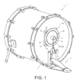
- FIG. 1 is a schematic perspective view of a bass drum 1 with the drum silencer 100 attached thereon according to the first embodiment.
- the bass drum 1 is an acoustic percussion instrument that includes a drumhead 2 serving as a struck head.
- the bass drum 1 can generate a tone specific to the bass drum 1 when the drumhead 2 is struck by a beater 4 that rotates with a stamp on a foot pedal 3.
- the drum silencer 100 is a device adapted to be attached to the drumhead 2 for reducing the sound generated during the performance.
- the drum silencer 100 mainly includes a struck body 10 and sucker members 20.
- the struck body 10 buffers the impact caused by the striking.
- the sucker members 20 suck the struck body 10 onto the drumhead 2.
- the struck body 10 of the drum silencer 100 is sucked to the drumhead 2 by the sucker members 20.
- the beater 4 rotates with the stamp to strike the struck body 10.
- FIG. 2A is a schematic top view of the drum silencer 100.
- FIG. 2B is a schematic bottom view of the drum silencer 100.
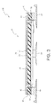
- FIG. 3 is a schematic cross-sectional view of the drum silencer 100 along the line III-III of FIG. 2A .
- the struck body 10 mainly includes a struck head portion 30 and a frame portion 40.
- the struck head portion 30 constitutes the struck head that is to be struck by the performer.
- the frame portion 40 supports a circumferential portion of the struck head portion 30.
- the struck head portion 30 is a membranous portion formed of a stretchable mesh material. By forming the struck head portion 30 using the stretchable mesh material, the struck head portion 30 can be made lighter. In addition, the struck head portion 30 is capable of buffering the impact of the struck head portion 30 when the struck head portion 30 is struck by the beater 4 (see FIG. 1 ).
- the struck head portion 30 is formed of the stretchable mesh material, when the struck head portion 30 is pressed and deformed by the striking of the beater 4, a restoring force of the struck head portion 30 can be utilized to push back the beater 4. Therefore, the performer can get a feel approximating to the striking feeling of striking the drumhead 2 directly (see FIG. 1 ).
- a buffer body 32 thicker than the struck head portion 30 is attached to a surface side (the paper front side of FIG. 2A ) of the struck head portion 30 of the struck body 10.
- the buffer body 32 includes a cushion portion 33 and a hard body 34.
- the cushion portion 33 is made of a spongy material and is attached to said surface side of the struck head portion 30.
- the hard body 34 is connected with the cushion portion 33 on a surface (the upper side of FIG. 3 ) opposite to a surface (the lower side of FIG. 3 ) to which the struck head portion 30 is attached.
- the hard body 34 is made of a hard material harder than the cushion portion 33.
- the material of the hard body 34 is harder and has higher abrasion resistance than the cushion portion 33 and may be woven or non-woven fabric, for example.
- the buffer body 32 by disposing the buffer body 32 at a position corresponding to a position struck by the beater 4, the impact applied to the struck head portion 30 when the beater 4 strikes the struck head portion 30 can be buffered by the cushion portion 33.
- the sound generated by the vibration of the drumhead 2 can be reduced.
- detachment of the sucker members 20 from the drumhead 2 can also be prevented.
- the foot pedal 3 is usually used in a state of being fixed to the bass drum 1. Therefore, a striking position on the struck body 10 which is struck by the beater 4 held by the foot pedal 3 is substantially consistent.
- the struck head portion 30 does not have the buffer body 32 attached thereon, the impact caused by the striking of the beater 4 may be concentrated on a portion of the struck head portion 30 when the struck head portion 30 is struck by the beater 4. Hence, only the mesh material, located at the portion of the struck head portion 30 where the striking is concentrated, becomes easily extended. In other words, the durability of the struck head portion 30 is reduced.
- the buffer body 32 is attached to the struck head portion 30 of the struck body 10. Hence, the impact applied to the struck head portion 30 can be dispersed. Consequently, the durability of the struck head portion 30 is improved.
- the hard body 34 is disposed facing the beater 4 to be struck by the beater 4 during the performance.
- the beater 4 can be prevented from sinking deep into the buffer body 32. Accordingly, a sag in the cushion portion 33 can be suppressed.
- the restoring force of the struck head portion 30 can also be utilized easily. As a result, the feel approximating to the striking feeling of actually striking the drumhead 2 can be obtained.
- the hard body 34 connected with the cushion portion 33 is struck. Accordingly, abrasion of the cushion portion 33, resulting from direct striking on the cushion portion 33, can be prevented. Further, the buffer body 32 is attached to the struck head portion 30 and the hard body 34 of the buffer body 32 is struck by the beater 4.
- the drum silencer 100 of the present invention can further reduce the sound (attack noise) generated by the striking.
- the frame portion 40 is an annular member formed of a resin material. By forming the frame portion 40 using the resin material, the frame portion 40 can be made lighter in comparison with using a metal material to form the frame portion 40.
- the frame portion 40 is fixed to the circumferential portion of the struck head portion 30 by insert-molding the struck head portion 30 in which tension is applied to the resin material that forms the frame portion 40.
- a mechanism for fixing the struck head portion 30 to the frame portion 40 can be omitted.
- the mechanism refers to a tension bolt for connecting the struck head portion 30 and the frame portion 40, and an internal thread structure for screwing the tension bolt, etc. Accordingly, the struck body 10 can be made lighter.
- the struck head portion 30 is fixed to the frame portion 40 with tension applied thereon.
- the beater 4 can be pushed back by the restoring force of the struck head portion 30 that is struck and pressed by the beater 4.
- the feel of striking the struck body 10 can be similar to the striking feeling of striking the drumhead 2.
- a vibration sensor 60 formed of a piezoelectric actuator, is disposed to adhere to a lower surface side (the paper front side of FIG. 2B ) of the frame portion 40. Therefore, with the drum silencer 100 installed to the bass drum 1, the bass drum 1 can be used as an electronic drum.
- recesses 41 adapted for accommodating elastic members 50 that are described later, are formed at four positions along a circumferential direction on the lower surface side (the lower side of FIG. 3 ) of the frame portion 40.
- the sucker members 20 are suckers for sucking the struck body 10 onto the drumhead 2 (see FIG. 1 ).
- the sucker members 20 are respectively connected with the recesses 41 formed in the frame portion 40 through the elastic members 50.
- sucker members 20 are disposed on the frame portion 40.
- three or fewer or five or more sucker members 20 may be disposed.
- the struck body 10 By disposing three or more sucker members 20 along the circumferential direction of the frame portion 40, the struck body 10 can be installed to the drumhead 2 stably. Therefore, when the struck body 10 is struck, the struck body 10 can be prevented from tilting to touch the drumhead 2.
- the elastic members 50 are members for buffering the impact transmitted from the struck body 10 to the sucker members 20.
- the elastic members 50 are respectively formed of a rubbery elastic body.
- the frame portion 40 and the sucker members 20 are connected through the elastic members 50.
- the struck body 10 is sucked to the drumhead 2 by the sucker members 20.
- a negative pressure is utilized to keep the drum silencer 100 and the drumhead 2 in close contact.
- the drumhead 2 can vibrate with the struck body 10 while a contact area between the drum silencer 100 and the drumhead 2 is suppressed. Therefore, the vibration of the struck body 10 that is struck can be transmitted to the drumhead 2, and hindrance to free vibration of the drumhead 2 caused by the striking can be suppressed.
- the struck body 10 remains attached to the drumhead 2 due to a suction force provided by the sucker members 20.
- the contact area between the struck body 10 and the drumhead 2 in the present invention can be suppressed.
- hindrance to free vibration of the drumhead, resulting from contact with the sucker members 20, can be suppressed.
- the struck head portion 30 is formed of the mesh material and the frame portion 40 is formed of the resin material, and the struck head portion 30 and the frame portion 40 are formed integrally by insert-molding.
- the struck body 10 can be made lighter. By doing so, attenuation of the vibration of the drumhead 2, caused by the weight of the struck body 10, can be suppressed. Hence, hindrance to free vibration of the drumhead 2 can also be suppressed. In other words, when the struck body 10 is struck, the tone specific to the bass drum 1 can be retained.
- the impact of the struck body 10 that comes with the striking of the beater 4 can be buffered by the struck head portion 30, the cushion portion 33, and the elastic members 50. Therefore, the impact transmitted to the drumhead 2 through the sucker members 20 can be reduced. Accordingly, the volume of the tone generated by the vibration of the drumhead 2 can be lowered. Further, a collision sound (attack noise) that occurs when the struck body 10 is struck can be reduced. Accordingly, cancellation of the tone generated by the vibration of the drumhead 2 due to the collision sound can be suppressed.
- the volume of the tone that occurs with the vibration of the drumhead 2 can be lowered and the collision sound that comes with the striking of the struck head portion 30 can be reduced. Accordingly, the tone specific to the bass drum 1 can be brought out. In other words, a sound approximating to the tone generated by directly striking the drumhead 2 can be produced predominantly.
- the struck body 10 and the drumhead 2 are connected through the sucker members 20. Therefore, in comparison with the case where the struck body 10 and the drumhead 2 are attached by using an adhesive tape, etc., a process of attaching and detaching the struck body 10 can be simplified. Further, in comparison with the case where the struck body 10 is connected with the bass drum 1 with use of a bolt, etc., the process of attaching and detaching the struck body 10 can be simplified.
- the second embodiment is explained hereinafter.
- the first embodiment illustrates a situation where the buffer body 32 is attached to the struck head portion 30, and the frame portion 40 and the sucker members 20 are connected through the elastic members 50.
- the buffer body 32 is omitted.
- the frame portion 40 and sucker members 220 are connected directly.
- the same reference numerals are used to denote components the same as the previous embodiment. Thus, detailed descriptions thereof are not repeated hereinafter.
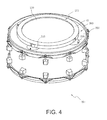
- FIG. 4 is a schematic perspective view of a snare drum 201 with the drum silencer 200 attached thereon according to the second embodiment.
- the snare drum 201 is an acoustic percussion instrument adapted to be struck with a stick, etc.
- the snare drum 201 can generate a tone specific to the snare drum 201 by striking a drumhead 202 with a stick, etc.
- the drum silencer 200 is a device adapted to be attached to the drumhead 202 for reducing the percussive sound generated during the performance.
- the drum silencer 200 mainly includes a struck body 210 and sucker members 220.
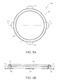
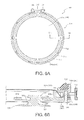
- FIG. 5A is a schematic top view of the drum silencer 200.
- FIG. 5B is a schematic cross-sectional view of the drum silencer 200 along the line Vb-Vb of FIG. 5A .
- the drum silencer 200 includes a struck head portion 230 and the frame portion 40.
- the struck head portion 230 and the frame portion 40 are formed integrally by insert-molding.
- the sucker members 220 are directly connected with the recesses 41 of the frame portion 40.
- an annular rim portion 242, formed of a rubbery elastic body, is attached to the upper surface side of the frame portion 40 (the upper side of FIG. 5B ).
- the rim portion 242 is a portion adapted to be struck when the performer performs a rim shot. By striking the rim portion 242 during the rim shot, the generated sound (attack noise) can be reduced.
- the drum silencer 100 (see FIG. 1 ) of the first embodiment is installed on the bass drum 1 that is struck by the beater 4 rotating with the stamp on the foot pedal 3. Moreover, in the drum silencer 100 (see FIG. 2A, FIG. 2B , and FIG. 3 ) of the first embodiment, the buffer body 32 including the cushion portion 33 and the elastic members 50 are disposed, besides the struck head portion 30 formed of the mesh material, to serve as the configuration for buffering the impact on the struck body 10. On the other hand, in comparison with the drum silencer 100 of the first embodiment, the impact and vibration applied to the drumhead 202 of the snare drum 201 that is struck by the stick are smaller.
- the drum silencer 100 of the first embodiment is installed to the snare drum 201, the vibration of the struck body 10 may be attenuated excessively and may not be sufficiently transmitted to the drumhead 202. In other words, the specific tone of the snare drum may hardly be produced.
- the buffer body 32 and the elastic members 50 are omitted, and the impact applied on the struck body 210 is attenuated by the struck head portion 30. Therefore, while the impact of the striking is suppressed from transmitting from the struck body 210 to the drumhead 202, the vibration of the struck body 210 can be easily transmitted to the drumhead 202.
- the struck body 210 can be made lighter correspondingly.
- attenuation of the vibration of the drumhead 202, caused by the weight of the struck body 210, can be suppressed.
- hindrance to free vibration of the drumhead 202 can also be suppressed. Therefore, when the struck body 210 is struck, the tone specific to the snare drum 201 can be retained.
- the vibration sensor 60 may also be disposed to adhere to the lower surface side (the lower side of FIG. 5B ) of the frame portion 40.
- the third embodiment is described with reference to FIG. 6A, FIG. 6B , FIG. 7A, and FIG. 7B .
- the first and the second embodiments illustrate a situation where the struck head portions 30 and 230 are formed integrally with the frame portion 40 by insert-molding.
- a struck head portion 330 and a frame portion 340 are formed individually.
- the same reference numerals are used to denote components the same as the previous embodiment. Thus, detailed descriptions thereof are not repeated hereinafter.
- FIG. 6A is a schematic top view of a drum silencer 300 according to the third embodiment.
- FIG. 6B is a schematic cross-sectional view of the drum silencer 300 along the line VIb-VIb of FIG. 6A .
- FIG. 7A is a schematic bottom view of the drum silencer 300.
- FIG. 7B is a partially enlarged view of the VIIb section of the drum silencer 300 of FIG. 7A .
- FIG. 7B depicts a part of a sucker member 320, a part of a sucker support portion 340d, and a hole 340e with broken lines.
- the drum silencer 300 includes a struck body 310 and sucker members 320.
- the sucker members 320 are detachably connected with the struck body 310. Except the configuration for attaching the sucker members 320 to a lower frame portion 340b that is to be described later, the struck body 310 has the same configuration as the drum previously developed by the applicants of the present invention and filed as a patent application (Japanese Patent Application No. 2013-084682 ).
- the struck body 310 mainly includes a struck head portion 330, a frame portion 340, a fixing bolt 343, a plurality of contact plates 344, and a tension ring 345.
- the struck head portion 330 includes a membrane portion 331a formed of a stretchable mesh material, and a fixing portion 331b fixed to a circumferential portion of the membrane portion 331a.
- the frame portion 340 includes an upper frame portion 340a and the lower frame portion 340b that hold the fixing portion 331b. Besides, the frame portion 340 has an annular shape.
- the fixing bolt 343 is used to fix the fixing portion 331b to the frame portion 340.
- the contact plates 344 are configured to displace in a radial direction with respect to the frame portion 340.
- the contact plates 344 apply tension to the membrane portion 331a when being displaced inward in the radial direction.
- the tension ring 345 is disposed on outer circumferential surfaces of these contact plates 344. Moreover, the tension ring 345 has a shape of an open loop.
- a rim portion 342, formed of a rubbery elastic body, is attached to an upper surface side of the upper frame portion 340a.
- the membrane portion 331a is stretched to be installed on a struck head support portion 340c that protrudes from the lower frame portion 340b. Tension is applied to the membrane portion 331a when the tension ring 345 is tightened.
- the tension of the membrane portion 331a can be adjusted properly to obtain the striking feeling the performer prefers.
- the sucker support portions 340d which protrude inward in the radial direction, are formed on the lower frame portion 340b at four positions equally spaced along the circumferential direction of the lower frame portion 340b.
- the holes 340e having a long circular shape are drilled to penetrate the sucker support portions 340d respectively and extend along the radial direction of the lower frame portion 340b.
- the sucker members 320 are respectively locked to the holes 340e.
- the sucker member 320 is formed of an elastic material. Moreover, the sucker member 320 is configured to be detachable from the lower frame portion 340b.
- the sucker member 320 includes a suction portion 321 and a locking portion 322.
- the suction portion 321 is configured as a sucker for sucking the drumhead 202 (see FIG. 4 ) of the snare drum 201.
- the locking portion 322 is connected with a surface of the suction portion 321, which is opposite to a surface by which the suction portion 321 is sucked to the drumhead 202.
- the locking portion 322 is a portion locked to the sucker support portion 340d.
- the locking portion 322 includes large diameter portions 323 and a small diameter portion 324.
- the large diameter portions 323 are a pair of portions, having a disc shape and facing each other.
- the small diameter portion 324 connects surfaces of the pair of large diameter portions that face each other.
- the small diameter portion 324 has an outer diameter smaller than an outer diameter of the large diameter portion 323.
- the pair of large diameter portions 323 and the small diameter portion 324 are disposed concentrically to form a substantially H shape (see FIG. 6B ).
- the large diameter portion 323 located on the side opposite to the suction portion 321 with respect to the small diameter portion 324 is pressed into the hole 340e from the lower side (the lower side of FIG. 6B ) of the sucker support portion 340d such that the large diameter portion 323 protrudes on the upper surface side of the lower frame portion 340b. Accordingly, the locking portion 322 is locked to the lower frame portion 340b.
- an interval between the pair of large diameter portions 323 facing each other is set to be slightly smaller than the thickness of the lower frame portion 340b (dimensions in the vertical direction of FIG. 6B ).
- the outer diameter of the small diameter portion 324 is set to be slightly larger than the width of the hole 340e (dimensions in the vertical direction of FIG. 7B ).
- the sucker support portion 340d can be held by the elastically deformed large diameter portions 323. Therefore, the locking portion 322 can be securely fixed to the sucker support portion 340d. Moreover, the small diameter portion 324 can be elastically deformed to be held by the inner circumferential surface of the hole 340e. Therefore, the locking portion 322 can be securely fixed to the sucker support portion 340d.
- the hole 340e has the long circular shape with a longitudinal direction consistent with the radial direction of the lower frame portion 340b. Hence, a locking position of the sucker member 320 can be adjusted along the radial direction of the frame portion 340.
- the membrane portion 331 a is stretched and disposed on the upper end surface of the struck head support portion 340c, and vibratability differs between a central portion of the membrane portion 331a and a portion close to the upper end portion of the struck head support portion 340c.
- a suction position of the sucker member 320 in the radial direction of the drumhead 202 (see FIG. 4 )
- a position at which vibration is transmitted from the sucker member 320 to the drumhead 202 when the struck body 310 is struck is changed.
- the tone of the snare drum 201 (see FIG. 4 ) that is generated by the vibration of the drumhead 202 can be varied.
- the vibration sensor 60 may also be disposed to adhere to the lower surface side (the lower side of FIG. 6B ) of the frame portion 40.
- the drum silencer 300 provided with the vibration sensor 60, attached to the snare drum 201, the snare drum 201 can be used as an electronic drum.
- the above embodiments illustrate a situation of using the drum silencer 100 of the first embodiment on the bass drum 1.
- the drum silencers 200 and 300 of the second and third embodiments are used on the snare drum 201.
- the present invention is not limited thereto.
- the drum silencer 100 of the first embodiment may also be used on a drum other than the bass drum 1.
- the drum silencers 200 and 300 of the second and third embodiments may also be used on a drum other than the snare drum 201.
- the first and second embodiments illustrate a situation where the frame portion 40 of the struck body 10 and 210 is fixed to the circumferential portion of the struck head portion 30 formed of the mesh material.
- the frame portion 40 may also be fixed to the circumferential portion of a struck head portion that is formed of a material other than the mesh material, such as a film-like, sponge-like, or rubber-like member, for example.
- the above embodiments illustrate a situation where the frame portions 40 and 340 are formed of the resin material.
- the frame portion may be formed using a material other than the resin material, such as a metal material, for example.
Abstract
Description
- The present invention relates to a drum silencer. Particularly, the present invention relates to a drum silencer that is capable of reducing a percussive sound while retaining a specific tone of an acoustic drum.
- A drum silencer is known to reduce a sound generated during performance in an environment where there is a need to avoid playing at high volume. Patent Literature 1 discloses a drum silencer, for example. According to Patent Literature 1, a silencer pad, fixed to a hoop and in close contact with a drumhead of a bass drum, is struck with a beater. In this way, vibration of the drumhead that occurs with the striking is attenuated early to reduce the percussive sound.
- However, the traditional drum silencer, as mentioned above, achieves reduction of the percussive sound by placing the silencer pad fixed to the hoop in close contact with the drumhead so as to attenuate the vibration of the drumhead early. In such a case, free vibration of the drumhead is hindered, which impairs the specific tone of the acoustic drum. As a result, the traditional drum silencer faces the problem that the tone generated by striking the silencer pad differs significantly from the tone generated by directly striking the drumhead.
- [Patent Literature 1]
US Patent Publication No. 2008/0264233 (FIG. 1 , etc.) - In view of the above, the present invention provides a drum silencer that is capable of reducing a percussive sound while retaining a specific tone of an acoustic drum.
- The drum silencer of the present invention achieves the following effects. In a struck body, a struck head portion supported by a frame portion has predetermined elasticity. Thus, a percussive sound generated by striking the struck head portion with a beater, a stick, or the like can be reduced.
- In addition, the struck body is sucked to a drumhead by a sucker member. Therefore, the drumhead can vibrate with the struck body through sucker member. Accordingly, the vibration of the struck body that is struck can be transmitted to the drumhead, and hindrance to free vibration of the drumhead due to the striking can be suppressed.
Further, the struck body is attached to the drumhead by a suction force provided by the sucker member. Therefore, in comparison with the case where the entire struck body is in close contact with the drumhead, a contact area between the struck body and the drumhead in the present invention can be suppressed. Hence, hindrance to free vibration of the drumhead, resulting from contact with the sucker member, can be reduced. - Accordingly, hindrance to free vibration of the drumhead can be suppressed while the percussive sound is reduced. In other words, a tone specific to the acoustic drum can be retained.
- According to another aspect of the present invention, in addition to the aforementioned effects, the drum silencer further achieves the following effects. Three or more sucker members are disposed along a circumferential direction of the frame portion. Thus, the struck body can be stably sucked to the drumhead. Therefore, when the struck body is struck, the struck body can be prevented from tilting to touch the drumhead.
- According to another aspect of the present invention, in addition to the aforementioned effects, the drum silencer further achieves the following effects. The frame portion is formed of a resin material. In comparison with using a metal material to form the frame portion, the frame portion of the present invention can be made lighter. Accordingly, the struck body can be made lighter. Thus, attenuation of the vibration of the drumhead, caused by the weight of the struck body, can be suppressed. Hence, the tone specific to the acoustic drum can be retained when the struck body is struck.
- According to another aspect of the present invention, in addition to the aforementioned effects, the drum silencer further achieves the following effects. The struck head portion is formed of a mesh material. Thus, the struck head portion can be made lighter.
- Moreover, the impact that occurs when the struck head portion is struck can be buffered. As a result, the percussive sound generated by the striking of the struck body can be reduced.
- According to another aspect of the present invention, in addition to the aforementioned effects, the drum silencer further achieves the following effects. In the struck body, the frame portion is fixed to the circumferential portion of the struck head portion by insert-molding the struck head portion in the resin material forming the frame portion. Thus, a mechanism for fixing the struck head portion to the frame portion can be omitted. As a result, the struck body can be made lighter.
- According to another aspect of the present invention, in addition to the aforementioned effects, the drum silencer further achieves the following effects. The struck body is fixed to the frame portion while tension is applied on the struck head portion. Thus, the beater, stick, or the like can be pushed back by a restoring force of the struck head portion when the struck head portion is struck and pressed by the beater, stick, or the like. In this way, the feel of striking the struck body can be similar to the striking feeling of striking the drumhead.
- According to another aspect of the present invention, in addition to the aforementioned effects, the drum silencer further achieves the following effects. A buffer body, formed of an elastic material and thicker than the struck head portion, is attached to the struck head portion. Thus, when the struck head portion is struck by the beater or the like installed on a foot pedal with a large force, the impact transmitted from the struck body to the drumhead can be reduced. Hence, the percussive sound generated by the striking of the struck body can be reduced.
- According to another aspect of the present invention, in addition to the aforementioned effects, the drum silencer further achieves the following effects. The sucker member is connected with the frame portion through an elastic member. Therefore, the impact transmitted from the struck body to the drumhead can be reduced. Hence, the percussive sound generated by the striking of the struck body can be reduced.
-
-
FIG. 1 is a schematic perspective view of a bass drum with a drum silencer attached thereon according to the first embodiment of the present invention. -
FIG. 2A is a schematic top view of the drum silencer. -
FIG. 2B is a schematic bottom view of the drum silencer. -
FIG. 3 is a schematic cross-sectional view of the drum silencer along the line III-III of -
FIG. 2A . -
FIG. 4 is a schematic perspective view of a snare drum with a drum silencer attached thereon according to the second embodiment. -
FIG. 5A is a schematic top view of the drum silencer. -
FIG. 5B is a schematic cross-sectional view of the drum silencer along the line Vb-Vb ofFIG. 5A . -
FIG. 6A is a schematic top view of a drum silencer according to the third embodiment. -
FIG. 6B is a schematic cross-sectional view of the drum silencer along the line VIb-VIb ofFIG. 6A . -
FIG. 7A is a schematic bottom view of the drum silencer. -
FIG. 7B is a partially enlarged view of the VIIb section of the drum silencer ofFIG. 7A . - Below exemplary embodiments of the present invention are described in detail with reference to the affixed figures. First, a usage example of a
drum silencer 100 according to the first embodiment of the present invention is described with reference toFIG. 1. FIG. 1 is a schematic perspective view of a bass drum 1 with thedrum silencer 100 attached thereon according to the first embodiment. - As shown in
FIG. 1 , the bass drum 1 is an acoustic percussion instrument that includes adrumhead 2 serving as a struck head. The bass drum 1 can generate a tone specific to the bass drum 1 when thedrumhead 2 is struck by a beater 4 that rotates with a stamp on afoot pedal 3. - The
drum silencer 100 is a device adapted to be attached to thedrumhead 2 for reducing the sound generated during the performance. Thedrum silencer 100 mainly includes a struckbody 10 andsucker members 20. The struckbody 10 buffers the impact caused by the striking. Thesucker members 20 suck the struckbody 10 onto thedrumhead 2. - The struck
body 10 of thedrum silencer 100 is sucked to thedrumhead 2 by thesucker members 20. When thefoot pedal 3 is stamped by the performer, the beater 4 rotates with the stamp to strike the struckbody 10. - Next, the
drum silencer 100 is described with reference toFIG. 2A, FIG. 2B andFIG. 3 .FIG. 2A is a schematic top view of thedrum silencer 100.FIG. 2B is a schematic bottom view of thedrum silencer 100.FIG. 3 is a schematic cross-sectional view of thedrum silencer 100 along the line III-III ofFIG. 2A . - As shown in
FIG. 2A, FIG. 2B orFIG. 3 , the struckbody 10 mainly includes a struckhead portion 30 and aframe portion 40. The struckhead portion 30 constitutes the struck head that is to be struck by the performer. Theframe portion 40 supports a circumferential portion of the struckhead portion 30. - The struck
head portion 30 is a membranous portion formed of a stretchable mesh material. By forming the struckhead portion 30 using the stretchable mesh material, the struckhead portion 30 can be made lighter. In addition, the struckhead portion 30 is capable of buffering the impact of the struckhead portion 30 when the struckhead portion 30 is struck by the beater 4 (seeFIG. 1 ). - Because the struck
head portion 30 is formed of the stretchable mesh material, when the struckhead portion 30 is pressed and deformed by the striking of the beater 4, a restoring force of the struckhead portion 30 can be utilized to push back the beater 4. Therefore, the performer can get a feel approximating to the striking feeling of striking thedrumhead 2 directly (seeFIG. 1 ). - Here, a
buffer body 32 thicker than the struckhead portion 30 is attached to a surface side (the paper front side ofFIG. 2A ) of the struckhead portion 30 of the struckbody 10. - The
buffer body 32 includes acushion portion 33 and ahard body 34. Thecushion portion 33 is made of a spongy material and is attached to said surface side of the struckhead portion 30. Thehard body 34 is connected with thecushion portion 33 on a surface (the upper side ofFIG. 3 ) opposite to a surface (the lower side ofFIG. 3 ) to which the struckhead portion 30 is attached. In addition, thehard body 34 is made of a hard material harder than thecushion portion 33.
Preferably, the material of thehard body 34 is harder and has higher abrasion resistance than thecushion portion 33 and may be woven or non-woven fabric, for example. - Here, when the struck
head portion 30 is struck by the beater 4 that rotates with the stamp on thefoot pedal 3, large impact is applied to the struckhead portion 30. The large impact is transmitted to thedrumhead 2 through thesucker members 20. The result is that the sound generated by the vibration of thedrumhead 2 increases. Moreover, due to the vibration of thedrumhead 2, thesucker members 20 may be detached from thedrumhead 2 easily. - In contrast to the above, by disposing the
buffer body 32 at a position corresponding to a position struck by the beater 4, the impact applied to the struckhead portion 30 when the beater 4 strikes the struckhead portion 30 can be buffered by thecushion portion 33. Thus, the sound generated by the vibration of thedrumhead 2 can be reduced. In addition, detachment of thesucker members 20 from thedrumhead 2 can also be prevented.
Besides, thefoot pedal 3 is usually used in a state of being fixed to the bass drum 1. Therefore, a striking position on the struckbody 10 which is struck by the beater 4 held by thefoot pedal 3 is substantially consistent. For this reason, if the struckhead portion 30 does not have thebuffer body 32 attached thereon, the impact caused by the striking of the beater 4 may be concentrated on a portion of the struckhead portion 30 when the struckhead portion 30 is struck by the beater 4. Hence, only the mesh material, located at the portion of the struckhead portion 30 where the striking is concentrated, becomes easily extended. In other words, the durability of the struckhead portion 30 is reduced.
In contrast, thebuffer body 32 is attached to the struckhead portion 30 of the struckbody 10. Hence, the impact applied to the struckhead portion 30 can be dispersed. Consequently, the durability of the struckhead portion 30 is improved. - Furthermore, in the state that the
drum silencer 100 is installed to thedrumhead 2, thehard body 34 is disposed facing the beater 4 to be struck by the beater 4 during the performance. - Therefore, the beater 4 can be prevented from sinking deep into the
buffer body 32. Accordingly, a sag in thecushion portion 33 can be suppressed. The restoring force of the struckhead portion 30 can also be utilized easily. As a result, the feel approximating to the striking feeling of actually striking thedrumhead 2 can be obtained. Thehard body 34 connected with thecushion portion 33 is struck. Accordingly, abrasion of thecushion portion 33, resulting from direct striking on thecushion portion 33, can be prevented.
Further, thebuffer body 32 is attached to the struckhead portion 30 and thehard body 34 of thebuffer body 32 is struck by the beater 4. Accordingly, a collision due to the striking can be buffered by thecushion portion 33 connected with thehard body 34 and the struckhead portion 30 to which thecushion portion 33 is attached. Thus, in comparison with directly striking on the struckhead portion 30, thedrum silencer 100 of the present invention can further reduce the sound (attack noise) generated by the striking. - The
frame portion 40 is an annular member formed of a resin material. By forming theframe portion 40 using the resin material, theframe portion 40 can be made lighter in comparison with using a metal material to form theframe portion 40. - Here, in the struck
body 10, theframe portion 40 is fixed to the circumferential portion of the struckhead portion 30 by insert-molding the struckhead portion 30 in which tension is applied to the resin material that forms theframe portion 40. - Thus, a mechanism for fixing the struck
head portion 30 to theframe portion 40 can be omitted. The mechanism refers to a tension bolt for connecting the struckhead portion 30 and theframe portion 40, and an internal thread structure for screwing the tension bolt, etc. Accordingly, the struckbody 10 can be made lighter. - Moreover, the struck
head portion 30 is fixed to theframe portion 40 with tension applied thereon. Thus, the beater 4 can be pushed back by the restoring force of the struckhead portion 30 that is struck and pressed by the beater 4. In this way, the feel of striking the struckbody 10 can be similar to the striking feeling of striking thedrumhead 2. - A
vibration sensor 60, formed of a piezoelectric actuator, is disposed to adhere to a lower surface side (the paper front side ofFIG. 2B ) of theframe portion 40. Therefore, with thedrum silencer 100 installed to the bass drum 1, the bass drum 1 can be used as an electronic drum. - Further, recesses 41, adapted for accommodating
elastic members 50 that are described later, are formed at four positions along a circumferential direction on the lower surface side (the lower side ofFIG. 3 ) of theframe portion 40. - The
sucker members 20 are suckers for sucking the struckbody 10 onto the drumhead 2 (seeFIG. 1 ). Thesucker members 20 are respectively connected with therecesses 41 formed in theframe portion 40 through theelastic members 50. - Here, in this embodiment, four
sucker members 20 are disposed on theframe portion 40. However, three or fewer or five ormore sucker members 20 may be disposed. - By disposing three or
more sucker members 20 along the circumferential direction of theframe portion 40, the struckbody 10 can be installed to thedrumhead 2 stably. Therefore, when the struckbody 10 is struck, the struckbody 10 can be prevented from tilting to touch thedrumhead 2. - The
elastic members 50 are members for buffering the impact transmitted from the struckbody 10 to thesucker members 20. Theelastic members 50 are respectively formed of a rubbery elastic body. Theframe portion 40 and thesucker members 20 are connected through theelastic members 50. Thus, the impact of the struckbody 10 that comes with the striking of the beater 4 (seeFIG. 1 ) can be buffered. Accordingly, the impact of the struckbody 10 can be suppressed from transmitting to thedrumhead 2 by thesucker members 20. Hence, the sound generated by the vibration of thedrumhead 2 can be reduced. In addition, detachment of thesucker members 20 from thedrumhead 2 can also be prevented. - The struck
body 10 is sucked to thedrumhead 2 by thesucker members 20. Thus, a negative pressure is utilized to keep thedrum silencer 100 and thedrumhead 2 in close contact. In this way, thedrumhead 2 can vibrate with the struckbody 10 while a contact area between thedrum silencer 100 and thedrumhead 2 is suppressed. Therefore, the vibration of the struckbody 10 that is struck can be transmitted to thedrumhead 2, and hindrance to free vibration of thedrumhead 2 caused by the striking can be suppressed.
In addition, the struckbody 10 remains attached to thedrumhead 2 due to a suction force provided by thesucker members 20. Therefore, in comparison with the case where the entire struckbody 10 is in close contact with thedrumhead 2, the contact area between thestruck body 10 and thedrumhead 2 in the present invention can be suppressed. Hence, hindrance to free vibration of the drumhead, resulting from contact with thesucker members 20, can be suppressed. - Furthermore, the struck
head portion 30 is formed of the mesh material and theframe portion 40 is formed of the resin material, and the struckhead portion 30 and theframe portion 40 are formed integrally by insert-molding. Thus, the struckbody 10 can be made lighter. By doing so, attenuation of the vibration of thedrumhead 2, caused by the weight of the struckbody 10, can be suppressed. Hence, hindrance to free vibration of thedrumhead 2 can also be suppressed. In other words, when the struckbody 10 is struck, the tone specific to the bass drum 1 can be retained. - Besides, the impact of the struck
body 10 that comes with the striking of the beater 4 can be buffered by the struckhead portion 30, thecushion portion 33, and theelastic members 50. Therefore, the impact transmitted to thedrumhead 2 through thesucker members 20 can be reduced. Accordingly, the volume of the tone generated by the vibration of thedrumhead 2 can be lowered. Further, a collision sound (attack noise) that occurs when the struckbody 10 is struck can be reduced. Accordingly, cancellation of the tone generated by the vibration of thedrumhead 2 due to the collision sound can be suppressed. - Like this, the volume of the tone that occurs with the vibration of the
drumhead 2 can be lowered and the collision sound that comes with the striking of the struckhead portion 30 can be reduced. Accordingly, the tone specific to the bass drum 1 can be brought out. In other words, a sound approximating to the tone generated by directly striking thedrumhead 2 can be produced predominantly. - Moreover, the struck
body 10 and thedrumhead 2 are connected through thesucker members 20. Therefore, in comparison with the case where the struckbody 10 and thedrumhead 2 are attached by using an adhesive tape, etc., a process of attaching and detaching the struckbody 10 can be simplified. Further, in comparison with the case where the struckbody 10 is connected with the bass drum 1 with use of a bolt, etc., the process of attaching and detaching the struckbody 10 can be simplified. - The second embodiment is explained hereinafter. The first embodiment illustrates a situation where the
buffer body 32 is attached to the struckhead portion 30, and theframe portion 40 and thesucker members 20 are connected through theelastic members 50. In the second embodiment, however, thebuffer body 32 is omitted. In addition, in the second embodiment, theframe portion 40 andsucker members 220 are connected directly. The same reference numerals are used to denote components the same as the previous embodiment. Thus, detailed descriptions thereof are not repeated hereinafter. - First, a usage example of a
drum silencer 200 according to the second embodiment is described with reference toFIG. 4. FIG. 4 is a schematic perspective view of asnare drum 201 with thedrum silencer 200 attached thereon according to the second embodiment. - As shown in
FIG. 4 , thesnare drum 201 is an acoustic percussion instrument adapted to be struck with a stick, etc. Thesnare drum 201 can generate a tone specific to thesnare drum 201 by striking adrumhead 202 with a stick, etc. - The
drum silencer 200 is a device adapted to be attached to thedrumhead 202 for reducing the percussive sound generated during the performance. Thedrum silencer 200 mainly includes astruck body 210 andsucker members 220. - Next, a detailed configuration of the
drum silencer 200 is described with reference toFIG. 5A and FIG. 5B. FIG. 5A is a schematic top view of thedrum silencer 200.FIG. 5B is a schematic cross-sectional view of thedrum silencer 200 along the line Vb-Vb ofFIG. 5A . - As shown in
FIG. 5A and FIG. 5B , thedrum silencer 200 includes a struckhead portion 230 and theframe portion 40. The struckhead portion 230 and theframe portion 40 are formed integrally by insert-molding. In addition, thesucker members 220 are directly connected with therecesses 41 of theframe portion 40. Further, anannular rim portion 242, formed of a rubbery elastic body, is attached to the upper surface side of the frame portion 40 (the upper side ofFIG. 5B ). - The
rim portion 242 is a portion adapted to be struck when the performer performs a rim shot. By striking therim portion 242 during the rim shot, the generated sound (attack noise) can be reduced. - Here, the drum silencer 100 (see
FIG. 1 ) of the first embodiment is installed on the bass drum 1 that is struck by the beater 4 rotating with the stamp on thefoot pedal 3. Moreover, in the drum silencer 100 (seeFIG. 2A, FIG. 2B , andFIG. 3 ) of the first embodiment, thebuffer body 32 including thecushion portion 33 and theelastic members 50 are disposed, besides the struckhead portion 30 formed of the mesh material, to serve as the configuration for buffering the impact on the struckbody 10. On the other hand, in comparison with thedrum silencer 100 of the first embodiment, the impact and vibration applied to thedrumhead 202 of thesnare drum 201 that is struck by the stick are smaller. For this reason, if thedrum silencer 100 of the first embodiment is installed to thesnare drum 201, the vibration of the struckbody 10 may be attenuated excessively and may not be sufficiently transmitted to thedrumhead 202. In other words, the specific tone of the snare drum may hardly be produced. - In contrast to the
drum silencer 100 of the first embodiment, in thedrum silencer 200 of the second embodiment, thebuffer body 32 and theelastic members 50 are omitted, and the impact applied on thestruck body 210 is attenuated by the struckhead portion 30. Therefore, while the impact of the striking is suppressed from transmitting from the struckbody 210 to thedrumhead 202, the vibration of the struckbody 210 can be easily transmitted to thedrumhead 202. - In addition, by omitting the
buffer body 32 and theelastic members 50, thestruck body 210 can be made lighter correspondingly. Thus, attenuation of the vibration of thedrumhead 202, caused by the weight of the struckbody 210, can be suppressed. Hence, hindrance to free vibration of thedrumhead 202 can also be suppressed. Therefore, when thestruck body 210 is struck, the tone specific to thesnare drum 201 can be retained.
Thevibration sensor 60 may also be disposed to adhere to the lower surface side (the lower side ofFIG. 5B ) of theframe portion 40. With thedrum silencer 200, provided with thevibration sensor 60, attached to thesnare drum 201, thesnare drum 201 can be used as an electronic drum. - Hereinafter, the third embodiment is described with reference to
FIG. 6A, FIG. 6B ,FIG. 7A, and FIG. 7B . The first and the second embodiments illustrate a situation where the struckhead portions frame portion 40 by insert-molding. In the third embodiment, however, astruck head portion 330 and aframe portion 340 are formed individually. The same reference numerals are used to denote components the same as the previous embodiment. Thus, detailed descriptions thereof are not repeated hereinafter. -
FIG. 6A is a schematic top view of adrum silencer 300 according to the third embodiment.FIG. 6B is a schematic cross-sectional view of thedrum silencer 300 along the line VIb-VIb ofFIG. 6A .FIG. 7A is a schematic bottom view of thedrum silencer 300.FIG. 7B is a partially enlarged view of the VIIb section of thedrum silencer 300 ofFIG. 7A . To simplify the illustration and to make the description more comprehensible,FIG. 7B depicts a part of asucker member 320, a part of asucker support portion 340d, and ahole 340e with broken lines. - As shown in
FIG. 6A and FIG. 6B , thedrum silencer 300 includes astruck body 310 andsucker members 320. Thesucker members 320 are detachably connected with thestruck body 310. Except the configuration for attaching thesucker members 320 to alower frame portion 340b that is to be described later, thestruck body 310 has the same configuration as the drum previously developed by the applicants of the present invention and filed as a patent application (Japanese Patent Application No.2013-084682 - The
struck body 310 mainly includes a struckhead portion 330, aframe portion 340, a fixingbolt 343, a plurality ofcontact plates 344, and atension ring 345. The struckhead portion 330 includes amembrane portion 331a formed of a stretchable mesh material, and a fixingportion 331b fixed to a circumferential portion of themembrane portion 331a. Theframe portion 340 includes anupper frame portion 340a and thelower frame portion 340b that hold the fixingportion 331b. Besides, theframe portion 340 has an annular shape. The fixingbolt 343 is used to fix the fixingportion 331b to theframe portion 340. Thecontact plates 344 are configured to displace in a radial direction with respect to theframe portion 340. Thecontact plates 344 apply tension to themembrane portion 331a when being displaced inward in the radial direction. Thetension ring 345 is disposed on outer circumferential surfaces of thesecontact plates 344. Moreover, thetension ring 345 has a shape of an open loop. Arim portion 342, formed of a rubbery elastic body, is attached to an upper surface side of theupper frame portion 340a. - The
membrane portion 331a is stretched to be installed on a struckhead support portion 340c that protrudes from thelower frame portion 340b. Tension is applied to themembrane portion 331a when thetension ring 345 is tightened. - That is, when a pair of
coupling members 346 respectively formed at two end portions of thetension ring 345 along the circumferential direction are screwed and coupled to each other by aconnection bolt 347, an inner diameter of thetension ring 345 is shortened. By doing so, thecontact plates 344 are pressed by an inner circumferential surface of thetension ring 345 to displace inward in the radial direction. Moreover, themembrane portion 331 a is placed on an upper end portion (end portion on the upper side ofFIG. 6B ) of the struckhead support portion 340c. Further, the fixingportion 331b that is fixed to the circumferential portion of themembrane portion 331a is fixed to theframe portion 340. Thus, as thecontact plates 344 are displaced inward in the radial direction, a portion of themembrane portion 331a located at an outer circumferential side of the struckhead support portion 340c is pulled downward. Accordingly, tension is applied to themembrane portion 331a. - Therefore, by adjusting a tightening amount of the
tension ring 345, the tension of themembrane portion 331a can be adjusted properly to obtain the striking feeling the performer prefers. - Here, the
sucker support portions 340d, which protrude inward in the radial direction, are formed on thelower frame portion 340b at four positions equally spaced along the circumferential direction of thelower frame portion 340b. Theholes 340e having a long circular shape are drilled to penetrate thesucker support portions 340d respectively and extend along the radial direction of thelower frame portion 340b. In addition, thesucker members 320 are respectively locked to theholes 340e. - The
sucker member 320 is formed of an elastic material. Moreover, thesucker member 320 is configured to be detachable from thelower frame portion 340b. Thesucker member 320 includes asuction portion 321 and a lockingportion 322. Thesuction portion 321 is configured as a sucker for sucking the drumhead 202 (seeFIG. 4 ) of thesnare drum 201. The lockingportion 322 is connected with a surface of thesuction portion 321, which is opposite to a surface by which thesuction portion 321 is sucked to thedrumhead 202. - The locking
portion 322 is a portion locked to thesucker support portion 340d. The lockingportion 322 includeslarge diameter portions 323 and asmall diameter portion 324. Thelarge diameter portions 323 are a pair of portions, having a disc shape and facing each other. Thesmall diameter portion 324 connects surfaces of the pair of large diameter portions that face each other. In addition, thesmall diameter portion 324 has an outer diameter smaller than an outer diameter of thelarge diameter portion 323. The pair oflarge diameter portions 323 and thesmall diameter portion 324 are disposed concentrically to form a substantially H shape (seeFIG. 6B ). - When installing the
sucker member 320 to thelower frame portion 340b, thelarge diameter portion 323 located on the side opposite to thesuction portion 321 with respect to thesmall diameter portion 324 is pressed into thehole 340e from the lower side (the lower side ofFIG. 6B ) of thesucker support portion 340d such that thelarge diameter portion 323 protrudes on the upper surface side of thelower frame portion 340b. Accordingly, the lockingportion 322 is locked to thelower frame portion 340b. - Here, an interval between the pair of
large diameter portions 323 facing each other is set to be slightly smaller than the thickness of thelower frame portion 340b (dimensions in the vertical direction ofFIG. 6B ). In addition, the outer diameter of thesmall diameter portion 324 is set to be slightly larger than the width of thehole 340e (dimensions in the vertical direction ofFIG. 7B ). - Accordingly, the
sucker support portion 340d can be held by the elastically deformedlarge diameter portions 323. Therefore, the lockingportion 322 can be securely fixed to thesucker support portion 340d. Moreover, thesmall diameter portion 324 can be elastically deformed to be held by the inner circumferential surface of thehole 340e. Therefore, the lockingportion 322 can be securely fixed to thesucker support portion 340d. - Further, the
hole 340e has the long circular shape with a longitudinal direction consistent with the radial direction of thelower frame portion 340b. Hence, a locking position of thesucker member 320 can be adjusted along the radial direction of theframe portion 340. - Here, the
membrane portion 331 a is stretched and disposed on the upper end surface of the struckhead support portion 340c, and vibratability differs between a central portion of themembrane portion 331a and a portion close to the upper end portion of the struckhead support portion 340c. Moreover, by adjusting a suction position of thesucker member 320 in the radial direction of the drumhead 202 (seeFIG. 4 ), a position at which vibration is transmitted from thesucker member 320 to thedrumhead 202 when thestruck body 310 is struck is changed. As a result, the tone of the snare drum 201 (seeFIG. 4 ) that is generated by the vibration of thedrumhead 202 can be varied.
Furthermore, thevibration sensor 60 may also be disposed to adhere to the lower surface side (the lower side ofFIG. 6B ) of theframe portion 40. With thedrum silencer 300, provided with thevibration sensor 60, attached to thesnare drum 201, thesnare drum 201 can be used as an electronic drum. - For example, the above embodiments illustrate a situation of using the
drum silencer 100 of the first embodiment on the bass drum 1. Moreover, thedrum silencers snare drum 201. However, the present invention is not limited thereto. Thedrum silencer 100 of the first embodiment may also be used on a drum other than the bass drum 1. In addition, thedrum silencers snare drum 201. - The first and second embodiments illustrate a situation where the
frame portion 40 of the struckbody head portion 30 formed of the mesh material. However, the present invention is not limited thereto. Theframe portion 40 may also be fixed to the circumferential portion of a struck head portion that is formed of a material other than the mesh material, such as a film-like, sponge-like, or rubber-like member, for example. - The above embodiments illustrate a situation where the
frame portions
Claims (15)
- A drum silencer (100, 200, 300), adapted to be attached to an acoustic drum (1, 201) and to be struck in place of a drumhead (2, 202) of the acoustic drum (1, 201) for reducing a sound generated during performance, the drum silencer (100, 200, 300) comprising:a struck body (10, 210, 310) comprising a struck head portion (30, 330) that has predetermined elasticity to be struck by a performer, and an annular frame portion (40, 340) that supports a circumferential portion of the struck head portion (30, 330) and has higher rigidity than the struck head portion (30, 330); andat least one sucker member (20, 220, 320) attached to the frame portion (40, 340) of the struck body (10, 210, 310) and sucking the struck body (10, 210, 310) onto the drumhead (2, 202).
- The drum silencer (100, 200, 300) according to claim 1, wherein the at least one sucker member (20, 220, 320) comprises three or more sucker members (20, 220, 320) disposed along a circumferential direction of the frame portion (40, 340).
- The drum silencer (100, 200, 300) according to claim 1 or 2, wherein the frame portion (40, 340) of the struck body (10, 210, 310) is formed of a resin material.
- The drum silencer (100, 200, 300) according to any one of claims 1 to 3, wherein the struck head portion (30, 330) is formed of a mesh material.
- The drum silencer (100, 200) according to claim 1, wherein the frame portion (40) of the struck body (10, 210) is formed of a resin material, the struck head portion (30) is formed of a mesh material, and in the struck body, the frame portion (40) is fixed to the circumferential portion of the struck head portion (30) by insert-molding the struck head portion (30) in the resin material forming the frame portion (40).
- The drum silencer (100, 200) according to claim 5, wherein the struck head portion (30) is fixed on the frame portion (40) in a state where tension is applied.
- The drum silencer (100) according to any one of claims 4 to 6, wherein, in the struck body (10), a buffer body (32) that is formed of an elastic material and thicker than the struck head portion (30) is attached to the struck head portion (30).
- The drum silencer (100) according to claim 7, wherein the buffer body (32) comprises:a cushion portion (33) attached to a surface of the struck head portion (30); anda hard body (34) connected with the cushion portion (33) on a surface opposite to the surface attached to the struck head portion (30).
- The drum silencer (100) according to any one of claims 1 to 8, wherein the at least one sucker member (20) is connected with the frame portion (40) through an elastic member (50) formed of an elastic material.
- The drum silencer (200) according to any one of claims 1 to 9, wherein a plurality of recesses (41) are formed on a lower surface side of the frame portion (40), along the circumferential direction, and the at least one sucker member (220) is respectively connected with the plurality of recesses (41) formed in the frame portion (40).
- The drum silencer (100, 200, 300) according to any one of claims 1 to 10, wherein the plurality of sucker members (20, 220, 320) are detachably connected with the struck body (10, 210, 310).
- The drum silencer (300) according to any one of claims 1 to 11, wherein a plurality of sucker support portions (340d) are formed on the frame portion (340)of the struck body (310) along the circumferential direction and protrude inward in a radial direction of the frame portion (340), and
the plurality of sucker members (320) are respectively locked to the plurality of sucker support portions (340d). - The drum silencer (300) according to claim 12, wherein a plurality of holes (340e) are formed to penetrate the plurality of sucker support portions (340d), and the plurality of sucker members (320) are locked to the plurality of holes (340e).
- The drum silencer (300) according to claim 13, wherein the hole (340e) has a long circular shape that extends in the radial direction of the frame portion (340).
- The drum silencer (100, 200, 300) according to any one of claims 1 to 14, wherein a vibration sensor (60) is disposed to adhere to a lower surface side of the frame portion (40, 340).
Applications Claiming Priority (1)
| Application Number | Priority Date | Filing Date | Title |
|---|---|---|---|
| JP2013200295A JP2015068851A (en) | 2013-09-26 | 2013-09-26 | Silencer for drum |
Publications (2)
| Publication Number | Publication Date |
|---|---|
| EP2863383A2 true EP2863383A2 (en) | 2015-04-22 |
| EP2863383A3 EP2863383A3 (en) | 2015-08-19 |
Family
ID=51176974
Family Applications (1)
| Application Number | Title | Priority Date | Filing Date |
|---|---|---|---|
| EP14177216.0A Withdrawn EP2863383A3 (en) | 2013-09-26 | 2014-07-16 | Drum silencer |
Country Status (4)
| Country | Link |
|---|---|
| US (1) | US20150082967A1 (en) |
| EP (1) | EP2863383A3 (en) |
| JP (1) | JP2015068851A (en) |
| CN (1) | CN104517590A (en) |
Cited By (2)
| Publication number | Priority date | Publication date | Assignee | Title |
|---|---|---|---|---|
| EP3346461A4 (en) * | 2015-09-04 | 2019-08-14 | Roland Corporation | Bass drum damper and bass drum |
| WO2020002819A1 (en) * | 2018-06-28 | 2020-01-02 | Redison | Detachable electronic emulation device that can be attached to an acoustic drum |
Families Citing this family (8)
| Publication number | Priority date | Publication date | Assignee | Title |
|---|---|---|---|---|
| US9390697B2 (en) * | 2013-12-23 | 2016-07-12 | Pearl Musical Instrument Co. | Removable electronic drum head and hoop for acoustic drum |
| CN106356041A (en) * | 2016-08-30 | 2017-01-25 | 太仓市方克乐器有限公司 | Bass drum having automatic music playing function and used for drum |
| JP6194130B1 (en) * | 2017-01-10 | 2017-09-06 | Atv株式会社 | Electronic percussion instrument |
| US10699681B2 (en) * | 2018-01-24 | 2020-06-30 | Drum Workshop, Inc. | Transportable drum kit |
| JP6977868B2 (en) * | 2018-03-20 | 2021-12-08 | ヤマハ株式会社 | Low noise device and vibration detector |
| US11854514B2 (en) | 2019-10-23 | 2023-12-26 | D'addario & Company, Inc. | Drumhead with reduced volume |
| JP7467970B2 (en) * | 2020-02-14 | 2024-04-16 | ヤマハ株式会社 | Percussion Instrument and Percussion Detector |
| US11508343B2 (en) * | 2022-03-01 | 2022-11-22 | Wernick Ltd. | Isolation mount for a percussion instrument |
Citations (2)
| Publication number | Priority date | Publication date | Assignee | Title |
|---|---|---|---|---|
| US20080264233A1 (en) | 2007-04-27 | 2008-10-30 | Gatzen Robert A | Bass drum mute |
| JP2013084682A (en) | 2011-10-06 | 2013-05-09 | Disco Abrasive Syst Ltd | Processing device |
Family Cites Families (12)
| Publication number | Priority date | Publication date | Assignee | Title |
|---|---|---|---|---|
| US3453924A (en) * | 1968-01-11 | 1969-07-08 | Merton Glick | Drum mute |
| JPS60159499U (en) * | 1984-03-31 | 1985-10-23 | 星野楽器株式会社 | electronic drum pad |
| US4759525A (en) * | 1987-07-09 | 1988-07-26 | Sun Company | Attachable beverage coaster |
| US5637819A (en) * | 1992-06-23 | 1997-06-10 | Rtom Corporation | Percussion instrument damping |
| US5385076A (en) * | 1994-06-20 | 1995-01-31 | Remo, Inc. | Reinforced drumhead |
| US5657954A (en) * | 1995-12-14 | 1997-08-19 | Better Sleep Mfg. Co. | Adjustable device for suction cup adhesion |
| US5986196A (en) * | 1996-01-18 | 1999-11-16 | Behrenfeld; Eric J. | Impact pad for a drum head |
| US5932823A (en) * | 1997-02-05 | 1999-08-03 | Jacobs; Malcolm W. | Drum practice pad and method of production |
| US5977473A (en) * | 1997-09-08 | 1999-11-02 | Adinolfi; Alfonso M. | Acoustic drum with shell wall embedded electronic trigger sensor and head to shell sound transfer arm |
| JP3835084B2 (en) * | 1999-11-15 | 2006-10-18 | ヤマハ株式会社 | Drum, sound reduction device and electronic percussion instrument head |
| US7179985B2 (en) * | 2005-04-13 | 2007-02-20 | Kieffa Drums, Llc | Hybrid electric/acoustic percussion instrument |
| JP5067214B2 (en) * | 2008-03-13 | 2012-11-07 | ヤマハ株式会社 | Electronic percussion instrument |
-
2013
- 2013-09-26 JP JP2013200295A patent/JP2015068851A/en active Pending
-
2014
- 2014-06-17 CN CN201410270205.1A patent/CN104517590A/en active Pending
- 2014-06-25 US US14/315,291 patent/US20150082967A1/en not_active Abandoned
- 2014-07-16 EP EP14177216.0A patent/EP2863383A3/en not_active Withdrawn
Patent Citations (2)
| Publication number | Priority date | Publication date | Assignee | Title |
|---|---|---|---|---|
| US20080264233A1 (en) | 2007-04-27 | 2008-10-30 | Gatzen Robert A | Bass drum mute |
| JP2013084682A (en) | 2011-10-06 | 2013-05-09 | Disco Abrasive Syst Ltd | Processing device |
Cited By (3)
| Publication number | Priority date | Publication date | Assignee | Title |
|---|---|---|---|---|
| EP3346461A4 (en) * | 2015-09-04 | 2019-08-14 | Roland Corporation | Bass drum damper and bass drum |
| WO2020002819A1 (en) * | 2018-06-28 | 2020-01-02 | Redison | Detachable electronic emulation device that can be attached to an acoustic drum |
| FR3083361A1 (en) * | 2018-06-28 | 2020-01-03 | Drumistic | REMOVABLE ELECTRONIC EMULATION DEVICE CAPABLE OF FIXING ON AN ACOUSTIC BATTERY |
Also Published As
| Publication number | Publication date |
|---|---|
| JP2015068851A (en) | 2015-04-13 |
| CN104517590A (en) | 2015-04-15 |
| US20150082967A1 (en) | 2015-03-26 |
| EP2863383A3 (en) | 2015-08-19 |
Similar Documents
| Publication | Publication Date | Title |
|---|---|---|
| EP2863383A2 (en) | Drum silencer | |
| US8258392B2 (en) | Stroke sensing device for percussion instruments | |
| JP3835084B2 (en) | Drum, sound reduction device and electronic percussion instrument head | |
| JP5897880B2 (en) | Cymbal pickup and stand with the same | |
| US9196237B2 (en) | Electronic percussion instrument | |
| EP2709099A1 (en) | Bass drum | |
| US20090229450A1 (en) | Electronic percussion instrument | |
| US7476794B2 (en) | Sound modification system | |
| US9053694B2 (en) | Electronic percussion instrument | |
| EP3346461B1 (en) | Bass drum damper and bass drum | |
| EP3506252A1 (en) | Cymbal damping tool and method of producing the same | |
| US20200402484A1 (en) | Sound damping device, sound damping method, and vibration detection device | |
| US9601095B2 (en) | Percussion surface apparatus | |
| TW201532032A (en) | Digital bass drum kick | |
| JP5163099B2 (en) | Electronic percussion instrument | |
| JP2018194631A (en) | Electronic drum | |
| CN113270083A (en) | Percussion detecting device and percussion instrument | |
| JP7076825B2 (en) | Anti-vibration mat | |
| EP3843082B1 (en) | Drum head and attachment method of cushion | |
| JP4506867B2 (en) | Electronic drum pad | |
| CN115885341A (en) | Electronic percussion instrument and percussion detection method | |
| CN117730366A (en) | Electronic percussion instrument and method for fixing face |
Legal Events
| Date | Code | Title | Description |
|---|---|---|---|
| PUAI | Public reference made under article 153(3) epc to a published international application that has entered the european phase |
Free format text: ORIGINAL CODE: 0009012 |
|
| 17P | Request for examination filed |
Effective date: 20140716 |
|
| AK | Designated contracting states |
Kind code of ref document: A2 Designated state(s): AL AT BE BG CH CY CZ DE DK EE ES FI FR GB GR HR HU IE IS IT LI LT LU LV MC MK MT NL NO PL PT RO RS SE SI SK SM TR |
|
| AX | Request for extension of the european patent |
Extension state: BA ME |
|
| PUAL | Search report despatched |
Free format text: ORIGINAL CODE: 0009013 |
|
| AK | Designated contracting states |
Kind code of ref document: A3 Designated state(s): AL AT BE BG CH CY CZ DE DK EE ES FI FR GB GR HR HU IE IS IT LI LT LU LV MC MK MT NL NO PL PT RO RS SE SI SK SM TR |
|
| AX | Request for extension of the european patent |
Extension state: BA ME |
|
| RIC1 | Information provided on ipc code assigned before grant |
Ipc: G10D 13/02 20060101AFI20150715BHEP |
|
| STAA | Information on the status of an ep patent application or granted ep patent |
Free format text: STATUS: THE APPLICATION IS DEEMED TO BE WITHDRAWN |
|
| 18D | Application deemed to be withdrawn |
Effective date: 20160220 |