EP2911554B1 - Oral care implement - Google Patents
Oral care implement Download PDFInfo
- Publication number
- EP2911554B1 EP2911554B1 EP13776938.6A EP13776938A EP2911554B1 EP 2911554 B1 EP2911554 B1 EP 2911554B1 EP 13776938 A EP13776938 A EP 13776938A EP 2911554 B1 EP2911554 B1 EP 2911554B1
- Authority
- EP
- European Patent Office
- Prior art keywords
- partition member
- oral care
- toothbrush
- opening
- wick
- Prior art date
- Legal status (The legal status is an assumption and is not a legal conclusion. Google has not performed a legal analysis and makes no representation as to the accuracy of the status listed.)
- Active
Links
Images

Classifications
-
- A—HUMAN NECESSITIES
- A61—MEDICAL OR VETERINARY SCIENCE; HYGIENE
- A61C—DENTISTRY; APPARATUS OR METHODS FOR ORAL OR DENTAL HYGIENE
- A61C19/00—Dental auxiliary appliances
- A61C19/06—Implements for therapeutic treatment
- A61C19/063—Medicament applicators for teeth or gums, e.g. treatment with fluorides
-
- A—HUMAN NECESSITIES
- A46—BRUSHWARE
- A46B—BRUSHES
- A46B11/00—Brushes with reservoir or other means for applying substances, e.g. paints, pastes, water
- A46B11/001—Brushes with reservoir or other means for applying substances, e.g. paints, pastes, water with integral reservoirs
-
- A—HUMAN NECESSITIES
- A46—BRUSHWARE
- A46B—BRUSHES
- A46B11/00—Brushes with reservoir or other means for applying substances, e.g. paints, pastes, water
- A46B11/0072—Details
- A46B11/0079—Arrangements for preventing undesired leakage or dispensing
- A46B11/0082—Means for closing, sealing or controlling the flow using capillary action
-
- A—HUMAN NECESSITIES
- A46—BRUSHWARE
- A46B—BRUSHES
- A46B11/00—Brushes with reservoir or other means for applying substances, e.g. paints, pastes, water
- A46B11/0072—Details
- A46B11/0093—Arrangements for catching drips or overflow
-
- A—HUMAN NECESSITIES
- A46—BRUSHWARE
- A46B—BRUSHES
- A46B15/00—Other brushes; Brushes with additional arrangements
- A46B15/0055—Brushes combined with other articles normally separate from the brushing process, e.g. combs, razors, mirrors
- A46B15/0081—Brushes with a scraper, e.g. tongue scraper
-
- A—HUMAN NECESSITIES
- A46—BRUSHWARE
- A46B—BRUSHES
- A46B9/00—Arrangements of the bristles in the brush body
- A46B9/02—Position or arrangement of bristles in relation to surface of the brush body, e.g. inclined, in rows, in groups
- A46B9/04—Arranged like in or for toothbrushes
-
- B—PERFORMING OPERATIONS; TRANSPORTING
- B05—SPRAYING OR ATOMISING IN GENERAL; APPLYING FLUENT MATERIALS TO SURFACES, IN GENERAL
- B05C—APPARATUS FOR APPLYING FLUENT MATERIALS TO SURFACES, IN GENERAL
- B05C11/00—Component parts, details or accessories not specifically provided for in groups B05C1/00 - B05C9/00
- B05C11/10—Storage, supply or control of liquid or other fluent material; Recovery of excess liquid or other fluent material
- B05C11/105—Storage, supply or control of liquid or other fluent material; Recovery of excess liquid or other fluent material by capillary action, e.g. using wicks
-
- A—HUMAN NECESSITIES
- A46—BRUSHWARE
- A46B—BRUSHES
- A46B2200/00—Brushes characterized by their functions, uses or applications
- A46B2200/10—For human or animal care
- A46B2200/1066—Toothbrush for cleaning the teeth or dentures
Definitions
- the present invention relates generally to oral care implements, and specifically to oral care implements having a reservoir that stores an oral care agent.
- Oral care implements are typically used by applying toothpaste to a bristle section followed by brushing regions of the oral cavity such as the teeth, tongue and/or gums.
- Some oral care implements are equipped with built-in fluid reservoirs and systems for delivering dentifrice and other oral care agents to the bristle section of the oral care implement.
- AU 2011 253 669 A1 discloses a toothbrush according to the preamble of claim 1.
- the present invention is directed to a toothbrush according to claim 1.
- the invention can be a toothbrush comprising: a handle extending along a longitudinal axis and having an internal reservoir containing an oral care fluid; a head coupled to the handle and having a plurality of tooth cleaning elements; an applicator located on the head; a partition member positioned within the internal reservoir that divides the internal reservoir into a storage chamber and an overflow chamber, the partition member comprising a first surface facing the storage chamber and a second surface facing the overflow chamber; a passageway extending through the partition member from the storage chamber to the overflow chamber, the passageway terminating as a first opening in the first surface of the partition member and as a second opening in the second surface of the partition member; and a wick member having a first end in fluid communication with the applicator and a second end terminating in an end surface that abuts the second surface of the partition member without penetrating the second opening of the partition member to prohibit axial movement of the wick member in a first axial direction.
- a reference toothbrush may comprise: a handle extending along a longitudinal axis and having an internal reservoir containing an oral care fluid; a head coupled to the handle and having a plurality of tooth cleaning elements; an applicator located on the head; a partition member positioned within the internal reservoir, the partition member separating the internal reservoir into a storage chamber and an overflow chamber, a passageway formed through the partition member and comprising an inlet section and a delivery section, the inlet section extending from the storage chamber to the delivery section, the delivery section extending from the inlet section to the overflow chamber, and wherein the inlet section has a transverse cross-sectional area that is greater than a transverse cross-sectional area of the delivery section; and a wick member having a first end in fluid communication with the applicator and a second end in fluid communication with the delivery section.
- Another reference toothbrush may comprise; a handle extending along a longitudinal axis and having an internal reservoir containing an oral care fluid; a head coupled to the handle and having a plurality of tooth cleaning elements; an applicator located on the head; a partition member positioned within the internal reservoir that divides the internal reservoir into a first chamber and a second chamber, the partition member comprising a first surface facing the first chamber and a second surface facing the second chamber; a passageway extending through the partition member from the first chamber to the second chamber, the passageway terminating as a first opening in the first surface of the partition member and as a second opening in the second surface of the partition member; and a wick member having a first end in fluid communication with the applicator and a second end terminating in an end surface having an outer perimeter that surrounds the second opening.
- an oral care implement 100 will be described in accordance with an embodiment of the present invention.
- the oral care implement 100 is in the form of a manual toothbrush.
- the oral care implement 100 can take on other forms such as being a powered toothbrush, a tongue scraper, a gum and soft tissue cleanser, a water pick, an interdental device, a tooth polisher, a specially designed ansate implement having tooth engaging elements or any other type of implement that is commonly used for oral care.
- inventive concepts discussed herein can be applied to any type of oral care implement unless a specific type of oral care implement is specified in the claims.
- the oral care implement generally comprises a handle 110 extending along a longitudinal axis A-A from a proximal end 111 to a distal end 112 and a head 120 coupled to the distal end 112 of the handle 110. Furthermore, an end cap 150 is coupled to the proximal end 111 of the handle 110.
- the handle 110 is an elongated structure that provides the mechanism by which the user can hold and manipulate the oral care implement 100 during use.
- the handle 110 has a generic shape with various contours, none of which are specifically limiting of the present invention.
- the handle 110 also comprises an inner surface 129 that defines an internal reservoir 140 containing an oral care fluid 141 therein and an outer surface 119 that is gripped by a user during use of the oral care implement 100.
- the end cap 150 is coupled to the handle to prevent the oral care fluid 141 from leaking out of the internal reservoir 140.
- the end cap 150 is removably coupled to the handle 110 so that the oral care fluid 141 contained within the internal reservoir 140 can be refilled upon depletion thereof.
- a user can refill the internal reservoir 140 with any desired oral care fluid 141, including the different types of oral care fluids discussed below.
- the end cap 150 may be permanently affixed to the handle 110.
- the oral care implement 100 upon depletion of the oral care fluid 141 the oral care implement 100 can either be used as a standard oral care implement 100 without the benefits of the oral care fluid 141, or the oral care implement 100 can be discarded.
- the internal reservoir 140 extends along the axial length of the handle 110 of the oral care implement 100.
- the internal reservoir 140 is capable of containing an amount of the oral care fluid 141 that is sufficient for multiple uses.
- the internal reservoir 140 may be smaller and only extend partially along the axial length of the handle 110.
- the reservoir 140 may only include enough of the oral care fluid 141 for a single use of the oral care implement 100.
- the oral care implement 100 can either be a disposable oral care implement that is discarded after one use, or the internal reservoir 140 can be refilled between uses as desired.
- a partition member 160 is positioned within the internal reservoir 140.
- the partition member 160 divides the internal reservoir 140 into a storage chamber 142 and an overflow chamber 143.
- the storage chamber 142 is the portion of the internal reservoir 140 that stores the oral care fluid 141 prior to use thereof and the overflow chamber 143 contains excess of the oral care fluid 141.
- all of the oral care fluid 141 is stored within the storage chamber 142 and the overflow chamber 143 is free of the oral care fluid 141.
- an expansion takes place within the storage chamber 142, such as due to altitude or temperature fluctuations, a portion of the oral care fluid 141 in the storage chamber 142 will flow into the overflow chamber 143.
- the overflow chamber 143 captures any of the oral care fluid 141 that drips off of the wick member 132 (discussed below).
- the details of the partition member 160 and the internal reservoir 140 will be discussed in more detail below with reference to FIG. 2 .
- the excess oral care fluid 141 in the overflow chamber 143 will return to the storage chamber 142 when the pressure or expansion in the storage chamber 142 subsides.
- the partition member 160 may simply divide the internal reservoir 140 into a first chamber and a second chamber. In such an embodiment, the partition member 140 will serve its function of ensuring correct axial positioning of the wick member.
- the oral care fluid 141 contained within the reservoir 140 is a material that provides oral health benefits to a user upon contact with a user's oral cavity.
- the oral care fluid 141 is a fluidic material.
- the oral care fluid 141 is a mouthwash solution that cleans the oral surfaces when applied thereto and provides the user with breath freshening benefits.
- the oral care fluid 141 is a tooth cleaning solution, such as a dentifrice.
- the oral care fluid 141 is not to be in any way limiting of the present invention and may include fluids having active or inactive agents that deliver therapeutic, cosmetic, experiential and/or sensorial benefits to a consumer during a tooth, soft tissue, tongue or interdental cleaning regimen.
- the oral care material can be an anti-sensitivity agent, fluoride, a tartar protection agent, an antibacterial agent, an oxidative or whitening agent, an enamel strengthening or repair agent, a tooth erosion preventing agent, a tooth sensitivity ingredient, a gum health active, a nutritional ingredient, a tartar control or antistain ingredient, an enzyme, a sensate ingredient, a flavor or flavor ingredient, a breath freshening ingredient, an oral malodor reducing agent, an anti-attachment agent or sealant, a diagnostic solution, an occluding agent, a dry mouth relief ingredient, a catalyst to enhance the activity of any of these agents, colorants or aesthetic ingredients, arginine bicarbonate, chlorohexidine, triclosan, CPC, zinc oxide and combinations thereof.
- the oral care fluid 141 is free of a dentifrice as the oral care fluid 141 is intended to supplement traditional brushing of the teeth rather than supplant it (hence its delivery to the rear surface of the head as opposed to the bristles in certain embodiments, as discussed below).
- the head 120 of the oral care implement 100 comprises a front surface 121 and an opposing rear surface 122.
- a plurality of tooth cleaning elements 123 extend from the front surface 121 of the head 120.
- the tooth cleaning elements 123 are generically illustrated as a block.
- the exact structure, pattern, orientation and material of the tooth cleaning elements 123 is not to be limiting of the present invention unless so specified in the claims.
- the term "tooth cleaning elements” is used in a generic sense to refer to any structure that can be used to clean, polish or wipe the teeth and/or soft oral tissue (e.g. tongue, cheek, gums, etc.) through relative surface contact.
- tooth cleaning elements include, without limitation, bristle tufts, filament bristles, fiber bristles, nylon bristles, spiral bristles, rubber bristles, elastomeric protrusions, flexible polymer protrusions, combinations thereof and/or structures containing such materials or combinations.
- Suitable elastomeric materials include any biocompatible resilient material suitable for uses in an oral hygiene apparatus.
- the elastomeric material of the tooth or soft tissue engaging elements has a hardness property in the range of A8 to A25 Shore hardness.
- One suitable elastomeric material is styrene-ethylene/butylene-styrene block copolymer (SEBS) manufactured by GLS Corporation. Nevertheless, SEBS material from other manufacturers or other materials within and outside the noted hardness range could be used.
- the tooth cleaning elements 123 of the present invention can be connected to the head 120 in any manner known in the art.
- staples/anchors, in-mold tufting (IMT) or anchor free tufting (AFT) could be used to mount the cleaning elements/tooth engaging elements.
- AFT anchor free tufting
- a plate or membrane is secured to the brush head such as by ultrasonic welding.
- the bristles extend through the plate or membrane.
- the free ends of the bristles on one side of the plate or membrane perform the cleaning function.
- the ends of the bristles on the other side of the plate or membrane are melted together by heat to be anchored in place.
- Any suitable form of cleaning elements may be used in the broad practice of this invention.
- the bristles could be mounted to tuft blocks or sections by extending through suitable openings in the tuft blocks so that the base of the bristles is mounted within or below the tuft block.
- a soft tissue cleanser 124 is positioned on and coupled to the rear surface 122 of the head 120.
- the soft tissue cleanser 124 comprises a pad portion 126 and a plurality of protuberances 125 protruding from the pad portion 126.
- each of the plurality of protuberances 125 is in the form of a nub.
- a nub generally refers to a column-like protrusion (without limitation to the cross-sectional shape of the protrusion) which is upstanding from a base surface.
- the protuberances 125 in the preferred construction have a height that is greater than the width at the base of the protuberance 125 (as measured in the longest direction).
- protuberances or nubs could include projections wherein the widths and heights are roughly the same or wherein the heights are somewhat smaller than the base widths.
- the base width can be substantially larger than the height.
- the plurality of protuberances 125 are preferably conically shaped.
- conically shaped or “conical” is meant to include true cones, frusto-conically shaped elements, and other shapes that taper to a narrow end and thereby resemble a cone irrespective of whether they are uniform, continuous in their taper, or have rounded cross-sections.
- the soft tissue cleanser 124 including the pad 126 and the protuberances 125 are formed from a resilient material, such as an injection molded thermoplastic elastomer.
- a suitable elastomeric soft tissue cleanser that may be used with the present invention and positioned on the rear surface 122 of the head 120 is disclosed in U.S. Patent No. 7,143,462, issued December 5, 2006 to the assignee of the present application.
- the protuberances 125 of the soft tissue cleanser 124 can take the form of elongated ridges, nubs, or combinations thereof.
- the invention is not limited to an embodiment that incorporates a soft tissue cleanser 124 on the rear surface 122 of the head 120 and in certain other embodiments the soft tissue cleanser 124 may be omitted.
- the handle 110 and the head 120 are integrally formed as a single unitary structure using a molding, milling, machining or other suitable process.
- the invention is not to be so limited and in certain other embodiments the handle 110 and the head 120 can be separately formed components that are operably coupled at a later stage of the manufacturing process by any suitable technique known in the art, including without limitation thermal or ultrasonic welding, a tight-fit assembly, a coupling sleeve, threaded engagement, adhesion, or fasteners.
- each of the handle 110 and the head 120 are formed of a rigid material, such as for example without limitation polymers and copolymers of ethylene, propylene, butadiene, vinyl compounds and polyesters such as polyethylene terephthalate.
- a rigid material such as for example without limitation polymers and copolymers of ethylene, propylene, butadiene, vinyl compounds and polyesters such as polyethylene terephthalate.
- the invention is not to be so limited in all embodiments and in certain other embodiments the handle 110 and/or the head 120 can be formed of other materials.
- the end cap 150 is also formed of a rigid material, such as one of the example materials listed above.
- the invention is not to be so limited and the end cap 150 can be formed of other materials, including resilient materials and non-plastic rigid materials such as wood, metal or the like.
- the handle 110 includes a grip component 115 in a thumb-grip region 116 of the handle 110.
- the grip component 115 is formed of a resilient material, such as a thermoplastic elastomer, and is coupled to the handle 110 via a technique known in the art such as injection molding or the like.
- the grip component 115 enhances user comfort when gripping the oral care implement 100 and minimizes or reduces the likelihood of a user's hand slipping on the handle 110 during use of the oral care implement 100 in a wet toothbrushing environment.
- the grip component 115 is only located on a front surface of the handle 110. However, the invention is not to be so limited in all embodiments and in certain other embodiments the grip component 115 may also be positioned on a rear surface and/or along the side surfaces of the handle 110.
- the grip component 115 includes a body portion 117 and a plurality of protuberances 118 extending outwardly from the body portion 117.
- the protuberances 118 are nubs extending from the body portion 117 of the grip component 115, such as the nubs discussed above with regard to the soft tissue cleanser 124.
- the invention is not to be so limited in all embodiments and the protuberances 118 can take on other shapes and forms such as being columnar protrusions, elongate ridges extending along the width of the body portion 117 of the grip component 115 or the like.
- the protuberances 118 provide an additional surface for preventing slippage during use of the oral care implement and for enhanced comfort.
- the handle 110 may be formed with additional resilient materials covering portions of or the entirety of the handle 110 to further enhance the gripability of the handle 110 during use.
- portions of the handle 110 that are typically gripped by a user's palm during use may be overmolded with a thermoplastic elastomer or other resilient material to further increase comfort to a user.
- the exact shape, contour and resilient material coverings on the handle 110 are not to be limiting of the present invention unless specifically claimed.
- the head 120 of the oral care implement 100 further comprises an applicator 130 located on the rear surface 122 of the head 120.
- the applicator 130 is located on the surface of the head 120 opposite the tooth cleaning elements 123.
- the invention is not to be so limited and in certain other embodiments the location of the applicator 130 is not limited to the rear surface 122 of the head 120.
- the applicator 130 may be located within the field of the plurality of tooth cleaning elements 111 on the front surface 121 of the head 120 or on any other desired region of the head 120 of the oral care implement 100.
- the applicator 130 may be located on the handle 110 or elsewhere on the oral care implement 100.
- the applicator 130 is surrounded by or embedded within the soft tissue cleanser 124. Furthermore, in the exemplified embodiment the applicator 130 has projections 131 that are exposed and contact a user's teeth and/or gums during use of the oral care implement 100. The projections 131 are formed integrally with the applicator 130 and follow the contours of the projections 125 of the soft tissue cleanser 124 to further enhance the cleaning of the user's teeth and/or gums.
- the head 120 of the oral care implement 100 further comprises a wick member 132 having a first end 133 that is in fluid communication with the applicator 130 and a second end 134 that is in fluid communication with the oral care fluid 141 contained within the internal reservoir 140. At least a portion of the wick member 132 is located within a channel 135 that is formed through the head 120 of the oral care implement 100 from a distal end 144 of the overflow chamber 143 of the internal reservoir 140 to the applicator 130. More specifically, in the exemplified embodiment the applicator 130 is exposed through an opening 139 on the rear surface 122 of the head 120.
- the channel 135 extends from the distal end 144 of the overflow chamber 143 to the opening 139 on the rear surface 122 of the head 120.
- the channel 135 provides a passageway through the oral care implement 100 from the internal reservoir 140 to the rear surface 122 of the head 120 where the applicator 130 is exposed for contact with a user's teeth and gums during use of the oral care implement 100.
- the exact positioning and location of the second end 134 of the wick member 132 will be discussed in more detail below with reference to FIGS. 2-4 .
- the wick member 132 has a cylindrical cross-sectional profile.
- the invention is not to be so limited in all embodiments and in certain other embodiments the wick member 132 may have other cross-sectional profiles.
- the wick member 132 is integrally formed with the applicator 130 out of a capillary material, including without limitation, a fibrous material, ceramic, porous plastic or combinations thereof.
- the oral care fluid 141 in the internal reservoir 140 is delivered to the applicator 130 solely by capillary action through the wick member 132.
- the applicator 130 and the wick member 132 can be separately formed out of two different types of the capillary materials discussed above.
- the oral care fluid 141 may flow through each of the wick member 132 and the applicator 130 at different flow rates depending on the material and pore size distribution of each component.
- the oral care fluid 141 may flow at a faster rate from the internal reservoir 140 onto the wick member 132 than from the wick member 132 onto the applicator 130 to prevent overdosing the oral care fluid 141 onto the user's teeth and/or gums during use of the oral care implement 100.
- the dose of the oral care fluid 141 applied to a user's teeth and/or gums is the amount of oral care fluid 141 saturating the applicator 130.
- the oral care fluid 141 on the applicator 130 will become depleted.
- the wick member 132 may comprise a first portion having a first capillarity and a second portion having a second capillarity such that the first and second capillarities are different.
- the first and second sections of the wick member 132 may be axial segments of the wick member 132.
- the second portion of the wick member 132 may be a sleeve that circumferentially surrounds the first portion of the wick member 132. The different capillarities of the first and second portions of the wick member 132 causes each of the first and second portions of the wick member 132 to transmit fluid through those portions at different rates (i.e., the first and second portions of the wick member 132 have different wicking rates).
- the different capillarities of the first and second portions of the wick member 132 can be achieved by utilizing a different pore size distribution, a different pore density, a combination of different pore sizes and pore densities, or using different materials for the first and second portions of the wick member 132.
- the materials that form the applicator 130 and the wick member 132 includes fibrous materials, ceramics and porous plastics, such as those available from Porex Technologies, Atlanta, GA.
- a fibrous material is an acrylic material identified as type number C10010, available from Teibow Hanbai Co., Ltd., Tokyo, Japan.
- a mixture of porous and/or fibrous materials may be provided which have a distribution of larger and smaller capillaries.
- the applicator 130 and the wick member 132 can be formed from a number of small capillaries that are connected to one another, or as a larger single capillary tube.
- delivery of the oral care fluid 141 from the internal reservoir 140 to the applicator 130 is described herein as being accomplished solely by capillary action, in certain other embodiments delivery may be achieved via mechanical action, mechanical pumps and/or electrical pumps or combinations thereof either solely or in addition to the capillary action.
- FIG. 2 illustrates a close-up view of area II of FIG. 1 .
- FIG. 2 illustrates a close-up view of the partition member 160 within the internal reservoir 140.
- the partition member 160 is a structural member that is positioned within the internal reservoir 140 to separate the internal reservoir 140 into the storage chamber 142 and the overflow chamber 143.
- the partition member 160 is positioned at a fixed axial location within the internal reservoir 140, which assists with ensuring that all components of the oral care implement 100 are located at the same position each time that the oral care implement is assembled 100.
- the partition member 160 by locating the partition member 160 at a fixed axial location within the internal reservoir 140 and by fixing the lengths of the wick member 132 and applicator 130, it can be ensured that all components are at the same position each time the oral care implement 100 is assembled.
- the partition member 160 is positioned within the internal reservoir 140 by an interference fit such that the partition member 160 is pressed into the internal reservoir 140 until an outer surface 161 of the partition member 160 fits snugly against the inner surface 129 of the handle 110 that defines the internal reservoir 140. In this manner, the partition member 160 is static and non-movable within the internal reservoir 140.
- the outer surface 161 of the partition member 160 comprises a first annular projection 107 and a second annular projection 108. The first and second annular projections 107, 108 are spaced from one another thereby forming a recessed region 109 on the outer surface 161 of the partition member 160.
- the outer surface 161 of the partition member 160 is a stepped surface.
- first and second annular projections 107, 108 of the outer surface 161 of the partition member 160 are in abutment with the inner surface 129 of the handle 110, the recessed region 109 of the outer surface 161 of the partition member 160 is spaced from the inner surface 129 of the handle 110 by a gap 105.
- the invention is not to be so limited by this structural arrangement in all embodiments and in certain other embodiments the outer surface 161 of the partition member 160 may be a non-stepped surface.
- the invention is not to be limited by an interference fit between the partition member 160 and the inner surface 129 of the handle 110 in all embodiments, and in certain other embodiments the partition member 160 may be stationarily positioned within the internal reservoir 140 by other techniques, such as adhesion, fasteners, threaded engagement, tight-fit assembly, ultrasonic or thermal welding, or a coupling sleeve.
- the partition member 160 can be formed from a variety of different types of materials, including without limitation polypropylene, low and high density polyethylene, thermoplastic elastomer and thermoplastic vulcanizate. Of course, the invention is not to be so limited and materials other than those mentioned herein can be used to form the partition member 160 in other embodiments.
- the partition member 160 comprises a first surface 162 facing the storage member 142 and a second surface 163 facing the overflow chamber 163.
- each of the first and second surfaces 162, 163 of the partition member 160 are transverse surfaces.
- each of the first and second surfaces 162, 163 of the partition member 160 are transverse to and oriented at a normal angle relative to the longitudinal axis A-A of the handle 110.
- a passageway 170 extends through the partition member 160 from the storage chamber 142 to the overflow chamber 143.
- the passageway 170 terminates as a first opening 171 in the first surface 162 of the partition member 160 and as a second opening 172 in the second surface 163 of the partition member 160.
- the first opening 171 has a diameter D O1
- the second opening 172 has a diameter D O2 such that the diameter D O1 of the first opening 171 is greater than the diameter D O2 of the second opening 172.
- the passageway 170 comprises an inlet section 173 and a delivery section 174.
- the inlet section 173 of the passageway 170 and the delivery section 174 of the passageway 170 are in fluid communication with one another, and the delivery section 174 and the inlet section 173 collectively form the entire passageway 170.
- the inlet section 174 comprises the first opening 171 and extends from the storage chamber 142 to the delivery section 174 and terminates at the first opening 171.
- the delivery section 174 comprises the second opening 172 and extends from the inlet section 173 to the overflow chamber 143 and terminates at the second opening 172.
- the inlet section 173 has a maximum transverse cross-sectional area that is greater than a maximum transverse cross-sectional area of the delivery section 174.
- the delivery section 174 is narrower than the inlet section 173 and prevents excess amounts of the oral care fluid 141 from flowing through the delivery section 174 and into contact with the wick member 132.
- the delivery section 174 minimizes the amount of the oral care fluid 141 that is able to exit the storage chamber 142 and reduces the likelihood of overdosing the wick member 132 with the oral care fluid 141.
- the partition member 160 comprises an upper section 165 and an annular sidewall 166 extending from the upper section 165 in a direction towards the storage chamber 142.
- the annular sidewall 166 of the partition member 160 comprises an inner surface 167 that defines the inlet section 173 of the passageway 170.
- the inner surface 167 of the annular sidewall 166 of the partition member 160 is a concave surface facing the storage chamber 142.
- the cross-sectional area of the inlet section 173 of the passageway 170 decreases with distance from the storage chamber 142.
- the invention is not to be so limited in all embodiments and in certain other embodiments the cross-sectional area of the inlet section 173 of the passageway can be constant.
- the upper section 165 of the partition member 160 comprises an inner surface 168 that defines the delivery section 174 of the passageway 170.
- the cross-sectional area of the delivery section 174 of the passageway 170 is constant.
- the invention is not to be so limited in all embodiments and in certain other embodiments the cross-sectional area of the delivery section 174 of the passageway 170 may increase and/or decrease with distance from the inlet section 173 of the passageway 170.
- the cross-sectional area of the delivery section 174 of the passageway 170 may decrease with distance from the inlet section 173 of the passageway 170 in order to further limit the amount of the oral care fluid 141 that is able to contact the wick member 132.
- the wick member 132 extends from the applicator 130, through the channel 135 and into the overflow chamber 143. More specifically, the second end 134 of the wick member 132 terminates in an end surface 136 that abuts the second surface 163 of the partition member 160. Due to the abutment of the end surface 136 of the second end 134 of the wick member 132 against the second surface 163 of the partition member 160, axial movement of the wick member 132 in a first axial direction towards the storage chamber 142 is prohibited.
- the end surface 136 of the second end 134 of the wick member 132 abuts against the second surface 163 of the partition member 160 at a location such that the end surface 136 of the second end 134 of the wick member 132 covers the second opening 172 in the second surface 163 of the partition member 160.
- the oral care fluid 141 is then soaked up by the wick member 132 and flows along the wick member 132 towards the applicator 130 via capillary action where the oral care fluid 141 is dispensed onto a user's tongue, gums, teeth and other oral surfaces during use of the oral care implement 100.
- the end surface 136 of the second end 134 of the wick member 132 is a transverse surface.
- the invention is not to be so limited in all embodiments as will be discussed in more detail below with reference to FIG. 4 .
- the end surface 136 of the second end 134 of the wick member 132 may not cover the second opening 172.
- the end surface 136 of the second end 134 of the wick member 132 may abut the second surface 163 of the partition member 160 while being positioned adjacent to the second opening 172.
- the oral care fluid 141 will flow through the second opening 172 and into the overflow chamber 143 where it will contact the wick member 132.
- the end surface 136 of the second end 134 of the wick member 132 has an outer perimeter 137 having a diameter D w .
- the diameter D w of the end surface 136 of the second end 134 of the wick member 132 is greater than the diameter D O2 of the second opening 172.
- the end surface 136 of the second end 134 of the wick member 132 is prevented from penetrating through the second opening 172 and into the delivery section 174 of the passageway 170 because the end surface 136 of the second end 134 of the wick member 132 abuts against the second surface 163 of the partition member 160.
- the outer perimeter 137 of the end surface 136 of the second end 134 of the wick member 132 is greater than the diameter D O2 of the second opening 172 and due to the relative positioning of the wick member 132 relative to the second opening 172, the outer perimeter 137 of the end surface 136 of the second end 134 of the wick member 132 surrounds the second opening 172 in the exemplified embodiment.
- the diameter D O1 of the first opening 171 in the first surface 162 of the partition member 160 is greater than the diameter D w of the outer perimeter 137 of the end surface 136 of the second end 134 of the wick member 132.
- the invention is not to be so limited and in certain other embodiments the diameter D O1 of the first opening 171 in the first surface 162 of the partition member 160 can be equal to or less than the diameter D w of the outer perimeter 137 of the end surface 136 of the second end 134 of the wick member 132.
- the wick member 132 has a constant diameter D w .
- the diameter D w of the wick member 132 may increase or decrease from the second end 134 of the wick member to the first end 133 of the wick member 132.
- FIG. 3 an alternative embodiment of a portion of an oral care implement 100A will be discussed in accordance with the present invention.
- the embodiment exemplified in FIG. 3 is similar to the embodiment exemplified in FIG. 2 with the exception of the shape of the partition member 160A and the relative positioning between the partition member 160A and the wick member 132A.
- components of the oral care implement 100A that are similar to or the same as components of the oral care implement 100 described above will not be described herein below in the interest of brevity.
- components of the oral care implement 100A will be numbered similarly to the same components of the oral care implement 100 except that the suffix "A" will be used.
- those components of the oral care implement 100A that are numbered but not described herein below have a similar function and/or structure to the similar component illustrated in FIGS. 1 and 2 and described above.
- the partition member 160A comprises a first surface 162A and a second surface 163A. Similar to the embodiment discussed above, the second surface 163A of the partition member 160A is a transverse surface. However, in FIG. 3 the transverse second surface 163A is a stepped surface. Specifically, the transverse second surface 163A comprises an upper surface 198A and a recessed surface 199A. Two opposing riser surfaces 196A, 197A extend from opposing ends of the recessed surface 199A to the upper surface 198A and form an annular shoulder. A socket 195A is formed between the opposing riser surfaces 196A, 197A having the recessed surface 199A as a floor of the socket 195A.
- the width of the recessed surface 199A is substantially equal to the diameter D w of the wick member 132A. However, in certain other embodiments the width of the recessed surface 199A may be slightly larger than the diameter D w of the wick member 132A.
- the partition member 160A comprises a first opening 171A in the first surface 162A of the partition member 160A and a second opening 172A in the second surface 163A of the partition member 160A.
- the wick member 132A comprises a second end 134A that terminates in an end surface 136A.
- the end surface 136A of the second end 134A of the wick member 132A protrudes through the second opening 172A in the second surface 163A of the partition member 160A and abuts the recessed surface 199A of the second surface 163A of the partition member 160A.
- the wick member 132A fits snugly within the socket 195A such that the outer surface 194A of the second end 134A of the wick member 132A is in contact with the riser surfaces 196A, 197A.
- the wick member 132A may not be in contact with both of the riser surfaces 196A, 197A.
- the socket 195A further facilitates proper positioning of the wick member 132A to ensure that the end surface 136A of the second end 134A of the wick member 132A is in fluid communication with the delivery section 174A of the passageway 170A that extends through the partition member 160A. Furthermore, the end surface 136A of the second end 134A of the wick member 132A abuts the second surface 163A of the partition member 160A to prohibit axial movement of the wick member 132A in a first axial direction, the first axial direction being in a direction towards the storage chamber 142A of the internal reservoir 140A in the exemplified embodiment.
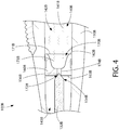
- FIG. 4 another alternative embodiment of a portion of an oral care implement 100B will be discussed in accordance with the present invention.
- the embodiment exemplified in FIG. 4 is similar to the embodiment exemplified in FIG. 2 with the exception of the shape of the partition member 160B and the relative positioning between the partition member 160B and the wick member 132B.
- components of the oral care implement 100B that are similar to or the same as components of the oral care implement 100 described above will not be described herein below in the interest of brevity.
- components of the oral care implement 100B will be numbered similarly to the same components of the oral care implement 100 except that the suffix "B" will be used.
- those components of the oral care implement 100B that are numbered but not described herein below have a similar function and/or structure to the similar component illustrated in FIGS. 1 and 2 and described above.
- the partition member 160B has a structure that is substantially similar to the partition member 160 illustrated in FIGS. 1 and 2 . Specifically, the partition member 160B has a first surface 162B and a second surface 163B. A passageway 170B is formed through the partition member 160B. A first opening 171B is formed into the first surface 162B of the partition member 160B and a second opening 172B is formed into the second surface 163B of the partition member 160B.
- the wick member 132B comprises a second end 134B that terminates in an end surface 136B that abuts the second surface 163B of the partition member 160B.
- the end surface 136B of the second end 134B of the wick member 132B is conical.
- a portion of the end surface 136B of the second end 134B of the wick member 132B is able to penetrate through the second opening 172B in the second surface 163B of the partition member 160B, a portion of the end surface 13B of the second end 134B of the wick member 132B still abuts against the second surface 163B of the partition member 160B.
- the wick member 132B is prohibited from axial movement in a first axial direction towards the storage chamber 142B due to the end surface 136B of the second end 134B of the wick member 132B abutting against the second surface 163B of the partition member 160B.
- FIGS. 2 , 3 and 4 The invention and inventive concepts described herein include various combinations of the embodiments illustrated in FIGS. 2 , 3 and 4 as would be understood by persons of ordinary skill in the art.
- the wick member 132B having the conical end surface 136B of FIG. 4 can be used with the partition member 160 illustrated in FIG. 2 .
- ranges are used as shorthand for describing each and every value that is within the range. Any value within the range can be selected as the terminus of the range. In the event of a conflict in a definition in the present disclosure and that of a cited reference, the present disclosure controls.
Description
- The present invention relates generally to oral care implements, and specifically to oral care implements having a reservoir that stores an oral care agent.
- Oral care implements, particularly toothbrushes, are typically used by applying toothpaste to a bristle section followed by brushing regions of the oral cavity such as the teeth, tongue and/or gums. Some oral care implements are equipped with built-in fluid reservoirs and systems for delivering dentifrice and other oral care agents to the bristle section of the oral care implement. There is a continuing need, however, for improved oral care implements for dispensing dentifrice and other oral care agents from the implement.
AU 2011 253 669 A1 - The present invention is directed to a toothbrush according to claim 1.
- In one embodiment, the invention can be a toothbrush comprising: a handle extending along a longitudinal axis and having an internal reservoir containing an oral care fluid; a head coupled to the handle and having a plurality of tooth cleaning elements; an applicator located on the head; a partition member positioned within the internal reservoir that divides the internal reservoir into a storage chamber and an overflow chamber, the partition member comprising a first surface facing the storage chamber and a second surface facing the overflow chamber; a passageway extending through the partition member from the storage chamber to the overflow chamber, the passageway terminating as a first opening in the first surface of the partition member and as a second opening in the second surface of the partition member; and a wick member having a first end in fluid communication with the applicator and a second end terminating in an end surface that abuts the second surface of the partition member without penetrating the second opening of the partition member to prohibit axial movement of the wick member in a first axial direction.
- A reference toothbrush may comprise: a handle extending along a longitudinal axis and having an internal reservoir containing an oral care fluid; a head coupled to the handle and having a plurality of tooth cleaning elements; an applicator located on the head; a partition member positioned within the internal reservoir, the partition member separating the internal reservoir into a storage chamber and an overflow chamber, a passageway formed through the partition member and comprising an inlet section and a delivery section, the inlet section extending from the storage chamber to the delivery section, the delivery section extending from the inlet section to the overflow chamber, and wherein the inlet section has a transverse cross-sectional area that is greater than a transverse cross-sectional area of the delivery section; and a wick member having a first end in fluid communication with the applicator and a second end in fluid communication with the delivery section.
- Another reference toothbrush may comprise; a handle extending along a longitudinal axis and having an internal reservoir containing an oral care fluid; a head coupled to the handle and having a plurality of tooth cleaning elements; an applicator located on the head; a partition member positioned within the internal reservoir that divides the internal reservoir into a first chamber and a second chamber, the partition member comprising a first surface facing the first chamber and a second surface facing the second chamber; a passageway extending through the partition member from the first chamber to the second chamber, the passageway terminating as a first opening in the first surface of the partition member and as a second opening in the second surface of the partition member; and a wick member having a first end in fluid communication with the applicator and a second end terminating in an end surface having an outer perimeter that surrounds the second opening.
- Further areas of applicability of the present invention will become apparent from the detailed description provided hereinafter. It should be understood that the detailed description and specific examples, while indicating the preferred embodiment of the invention, are intended for purposes of illustration only and are not intended to limit the scope of the invention as defined in the appended claims.
- The present invention will become more fully understood from the detailed description and the accompanying drawings, wherein:
-
Figure 1 is a cross-sectional view of an oral care implement in accordance with an embodiment of the present invention; -
Figure 2 is a close-up of area II ofFIG. 1 ; -
Figure 3 is a first alternative embodiment of the close-up ofFIG. 2 ; and -
Figure 4 is a second alternative embodiment of the close-up ofFIG. 2 . - The following description of the preferred embodiment(s) is merely exemplary in nature and is in no way intended to limit the invention, its application, or uses.
- The description of illustrative embodiments according to principles of the present invention is intended to be read in connection with the accompanying drawings, which are to be considered part of the entire written description. In the description of embodiments of the invention disclosed herein, any reference to direction or orientation is merely intended for convenience of description and is not intended in any way to limit the scope of the present invention. Relative terms such as "lower," "upper," "horizontal," "vertical," "above," "below," "up," "down," "top" and "bottom" as well as derivatives thereof (e.g., "horizontally," "downwardly," "upwardly," etc.) should be construed to refer to the orientation as then described or as shown in the drawing under discussion. These relative terms are for convenience of description only and do not require that the apparatus be constructed or operated in a particular orientation unless explicitly indicated as such. Terms such as "attached," "affixed," "connected," "coupled," "interconnected," and similar refer to a relationship wherein structures are secured or attached to one another either directly or indirectly through intervening structures, as well as both movable or rigid attachments or relationships, unless expressly described otherwise. Moreover, the features and benefits of the invention are illustrated by reference to the exemplified embodiments. Accordingly, the invention expressly should not be limited to such exemplary embodiments illustrating some possible non-limiting combination of features that may exist alone or in other combinations of features; the scope of the invention being defined by the claims appended hereto.
- Referring first to
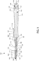
FIG. 1 , anoral care implement 100 will be described in accordance with an embodiment of the present invention. In the exemplified embodiment, theoral care implement 100 is in the form of a manual toothbrush. However, in certain other embodiments theoral care implement 100 can take on other forms such as being a powered toothbrush, a tongue scraper, a gum and soft tissue cleanser, a water pick, an interdental device, a tooth polisher, a specially designed ansate implement having tooth engaging elements or any other type of implement that is commonly used for oral care. Thus, it is to be understood that the inventive concepts discussed herein can be applied to any type of oral care implement unless a specific type of oral care implement is specified in the claims. - The oral care implement generally comprises a
handle 110 extending along a longitudinal axis A-A from aproximal end 111 to adistal end 112 and ahead 120 coupled to thedistal end 112 of thehandle 110. Furthermore, anend cap 150 is coupled to theproximal end 111 of thehandle 110. Thehandle 110 is an elongated structure that provides the mechanism by which the user can hold and manipulate the oral care implement 100 during use. Thehandle 110 has a generic shape with various contours, none of which are specifically limiting of the present invention. Furthermore, thehandle 110 also comprises aninner surface 129 that defines aninternal reservoir 140 containing anoral care fluid 141 therein and anouter surface 119 that is gripped by a user during use of the oral care implement 100. Theend cap 150 is coupled to the handle to prevent theoral care fluid 141 from leaking out of theinternal reservoir 140. - In certain embodiments, the
end cap 150 is removably coupled to thehandle 110 so that theoral care fluid 141 contained within theinternal reservoir 140 can be refilled upon depletion thereof. In such embodiments, with theend cap 150 removed from the handle 110 a user can refill theinternal reservoir 140 with any desiredoral care fluid 141, including the different types of oral care fluids discussed below. However, in certain other embodiments theend cap 150 may be permanently affixed to thehandle 110. In such embodiments, upon depletion of theoral care fluid 141 theoral care implement 100 can either be used as a standard oral care implement 100 without the benefits of theoral care fluid 141, or theoral care implement 100 can be discarded. - In the exemplified embodiment, the
internal reservoir 140 extends along the axial length of thehandle 110 of the oral care implement 100. Thus, theinternal reservoir 140 is capable of containing an amount of theoral care fluid 141 that is sufficient for multiple uses. Of course, in other embodiments theinternal reservoir 140 may be smaller and only extend partially along the axial length of thehandle 110. In certain such embodiments, thereservoir 140 may only include enough of theoral care fluid 141 for a single use of the oral care implement 100. In such embodiments, theoral care implement 100 can either be a disposable oral care implement that is discarded after one use, or theinternal reservoir 140 can be refilled between uses as desired. - A
partition member 160 is positioned within theinternal reservoir 140. Thepartition member 160 divides theinternal reservoir 140 into astorage chamber 142 and anoverflow chamber 143. Thestorage chamber 142 is the portion of theinternal reservoir 140 that stores theoral care fluid 141 prior to use thereof and theoverflow chamber 143 contains excess of theoral care fluid 141. Under normal conditions, all of theoral care fluid 141 is stored within thestorage chamber 142 and theoverflow chamber 143 is free of theoral care fluid 141. When an expansion takes place within thestorage chamber 142, such as due to altitude or temperature fluctuations, a portion of theoral care fluid 141 in thestorage chamber 142 will flow into theoverflow chamber 143. Specifically, temperature fluctuations and altitude fluctuations cause air volume fluctuations within thestorage chamber 142, which will cause theoral care fluid 141 to flow from thestorage chamber 142 into theoverflow chamber 143. Furthermore, theoverflow chamber 143 captures any of theoral care fluid 141 that drips off of the wick member 132 (discussed below). The details of thepartition member 160 and theinternal reservoir 140 will be discussed in more detail below with reference toFIG. 2 . In certain embodiments, the excessoral care fluid 141 in theoverflow chamber 143 will return to thestorage chamber 142 when the pressure or expansion in thestorage chamber 142 subsides. - Furthermore, while the invention is discussed below (and above) in terms of the
partition member 160 dividing theinternal reservoir 140 into astorage chamber 142 and anoverflow chamber 143, in certain embodiments of the invention in which overflow is not of concern, thepartition member 160 may simply divide theinternal reservoir 140 into a first chamber and a second chamber. In such an embodiment, thepartition member 140 will serve its function of ensuring correct axial positioning of the wick member. - The
oral care fluid 141 contained within thereservoir 140 is a material that provides oral health benefits to a user upon contact with a user's oral cavity. In one embodiment, theoral care fluid 141 is a fluidic material. For example, in certain embodiments theoral care fluid 141 is a mouthwash solution that cleans the oral surfaces when applied thereto and provides the user with breath freshening benefits. In other embodiments, theoral care fluid 141 is a tooth cleaning solution, such as a dentifrice. Of course, theoral care fluid 141 is not to be in any way limiting of the present invention and may include fluids having active or inactive agents that deliver therapeutic, cosmetic, experiential and/or sensorial benefits to a consumer during a tooth, soft tissue, tongue or interdental cleaning regimen. Specifically, the oral care material can be an anti-sensitivity agent, fluoride, a tartar protection agent, an antibacterial agent, an oxidative or whitening agent, an enamel strengthening or repair agent, a tooth erosion preventing agent, a tooth sensitivity ingredient, a gum health active, a nutritional ingredient, a tartar control or antistain ingredient, an enzyme, a sensate ingredient, a flavor or flavor ingredient, a breath freshening ingredient, an oral malodor reducing agent, an anti-attachment agent or sealant, a diagnostic solution, an occluding agent, a dry mouth relief ingredient, a catalyst to enhance the activity of any of these agents, colorants or aesthetic ingredients, arginine bicarbonate, chlorohexidine, triclosan, CPC, zinc oxide and combinations thereof. In certain embodiments, theoral care fluid 141 is free of a dentifrice as theoral care fluid 141 is intended to supplement traditional brushing of the teeth rather than supplant it (hence its delivery to the rear surface of the head as opposed to the bristles in certain embodiments, as discussed below). - The
head 120 of the oral care implement 100 comprises afront surface 121 and an opposingrear surface 122. A plurality oftooth cleaning elements 123 extend from thefront surface 121 of thehead 120. In the exemplified embodiment, thetooth cleaning elements 123 are generically illustrated as a block. The exact structure, pattern, orientation and material of thetooth cleaning elements 123 is not to be limiting of the present invention unless so specified in the claims. Thus, as used herein, the term "tooth cleaning elements" is used in a generic sense to refer to any structure that can be used to clean, polish or wipe the teeth and/or soft oral tissue (e.g. tongue, cheek, gums, etc.) through relative surface contact. Common examples of "tooth cleaning elements" include, without limitation, bristle tufts, filament bristles, fiber bristles, nylon bristles, spiral bristles, rubber bristles, elastomeric protrusions, flexible polymer protrusions, combinations thereof and/or structures containing such materials or combinations. Suitable elastomeric materials include any biocompatible resilient material suitable for uses in an oral hygiene apparatus. To provide optimum comfort as well as cleaning benefits, the elastomeric material of the tooth or soft tissue engaging elements has a hardness property in the range of A8 to A25 Shore hardness. One suitable elastomeric material is styrene-ethylene/butylene-styrene block copolymer (SEBS) manufactured by GLS Corporation. Nevertheless, SEBS material from other manufacturers or other materials within and outside the noted hardness range could be used. - The
tooth cleaning elements 123 of the present invention can be connected to thehead 120 in any manner known in the art. For example, staples/anchors, in-mold tufting (IMT) or anchor free tufting (AFT) could be used to mount the cleaning elements/tooth engaging elements. In AFT, a plate or membrane is secured to the brush head such as by ultrasonic welding. The bristles extend through the plate or membrane. The free ends of the bristles on one side of the plate or membrane perform the cleaning function. The ends of the bristles on the other side of the plate or membrane are melted together by heat to be anchored in place. Any suitable form of cleaning elements may be used in the broad practice of this invention. Alternatively, the bristles could be mounted to tuft blocks or sections by extending through suitable openings in the tuft blocks so that the base of the bristles is mounted within or below the tuft block. - In the exemplified embodiment, a
soft tissue cleanser 124 is positioned on and coupled to therear surface 122 of thehead 120. Thesoft tissue cleanser 124 comprises apad portion 126 and a plurality ofprotuberances 125 protruding from thepad portion 126. In the exemplified embodiment, each of the plurality ofprotuberances 125 is in the form of a nub. As used herein a "nub" generally refers to a column-like protrusion (without limitation to the cross-sectional shape of the protrusion) which is upstanding from a base surface. In a general sense, theprotuberances 125 in the preferred construction have a height that is greater than the width at the base of the protuberance 125 (as measured in the longest direction). Nevertheless, protuberances or nubs could include projections wherein the widths and heights are roughly the same or wherein the heights are somewhat smaller than the base widths. Moreover, in some circumstances (e.g., where the protuberances taper to a tip or include a base portion that narrows to a smaller projection), the base width can be substantially larger than the height. - In one preferred arrangement of the
soft tissue cleanser 124, the plurality ofprotuberances 125 are preferably conically shaped. As used herein, "conically shaped" or "conical" is meant to include true cones, frusto-conically shaped elements, and other shapes that taper to a narrow end and thereby resemble a cone irrespective of whether they are uniform, continuous in their taper, or have rounded cross-sections. In the exemplified embodiment, thesoft tissue cleanser 124 including thepad 126 and theprotuberances 125 are formed from a resilient material, such as an injection molded thermoplastic elastomer. Without intending to be limited, an example of a suitable elastomeric soft tissue cleanser that may be used with the present invention and positioned on therear surface 122 of thehead 120 is disclosed inU.S. Patent No. 7,143,462, issued December 5, 2006 to the assignee of the present application. In certain other embodiments, theprotuberances 125 of thesoft tissue cleanser 124 can take the form of elongated ridges, nubs, or combinations thereof. Furthermore, the invention is not limited to an embodiment that incorporates asoft tissue cleanser 124 on therear surface 122 of thehead 120 and in certain other embodiments thesoft tissue cleanser 124 may be omitted. - In the exemplified embodiment, the
handle 110 and thehead 120 are integrally formed as a single unitary structure using a molding, milling, machining or other suitable process. However, the invention is not to be so limited and in certain other embodiments thehandle 110 and thehead 120 can be separately formed components that are operably coupled at a later stage of the manufacturing process by any suitable technique known in the art, including without limitation thermal or ultrasonic welding, a tight-fit assembly, a coupling sleeve, threaded engagement, adhesion, or fasteners. - In certain embodiments, each of the
handle 110 and thehead 120 are formed of a rigid material, such as for example without limitation polymers and copolymers of ethylene, propylene, butadiene, vinyl compounds and polyesters such as polyethylene terephthalate. Of course, the invention is not to be so limited in all embodiments and in certain other embodiments thehandle 110 and/or thehead 120 can be formed of other materials. Furthermore, in the exemplified embodiment theend cap 150 is also formed of a rigid material, such as one of the example materials listed above. However, the invention is not to be so limited and theend cap 150 can be formed of other materials, including resilient materials and non-plastic rigid materials such as wood, metal or the like. - In the exemplified embodiment, the
handle 110 includes agrip component 115 in a thumb-grip region 116 of thehandle 110. Thegrip component 115 is formed of a resilient material, such as a thermoplastic elastomer, and is coupled to thehandle 110 via a technique known in the art such as injection molding or the like. Thegrip component 115 enhances user comfort when gripping the oral care implement 100 and minimizes or reduces the likelihood of a user's hand slipping on thehandle 110 during use of the oral care implement 100 in a wet toothbrushing environment. In the exemplified embodiment, thegrip component 115 is only located on a front surface of thehandle 110. However, the invention is not to be so limited in all embodiments and in certain other embodiments thegrip component 115 may also be positioned on a rear surface and/or along the side surfaces of thehandle 110. - The
grip component 115 includes abody portion 117 and a plurality ofprotuberances 118 extending outwardly from thebody portion 117. In certain embodiments, theprotuberances 118 are nubs extending from thebody portion 117 of thegrip component 115, such as the nubs discussed above with regard to thesoft tissue cleanser 124. Of course, the invention is not to be so limited in all embodiments and theprotuberances 118 can take on other shapes and forms such as being columnar protrusions, elongate ridges extending along the width of thebody portion 117 of thegrip component 115 or the like. Theprotuberances 118 provide an additional surface for preventing slippage during use of the oral care implement and for enhanced comfort. - In addition to the
grip component 115, thehandle 110 may be formed with additional resilient materials covering portions of or the entirety of thehandle 110 to further enhance the gripability of thehandle 110 during use. For example, portions of thehandle 110 that are typically gripped by a user's palm during use may be overmolded with a thermoplastic elastomer or other resilient material to further increase comfort to a user. The exact shape, contour and resilient material coverings on thehandle 110 are not to be limiting of the present invention unless specifically claimed. - The
head 120 of the oral care implement 100 further comprises anapplicator 130 located on therear surface 122 of thehead 120. Specifically, theapplicator 130 is located on the surface of thehead 120 opposite thetooth cleaning elements 123. Of course, the invention is not to be so limited and in certain other embodiments the location of theapplicator 130 is not limited to therear surface 122 of thehead 120. Specifically, in certain other embodiments theapplicator 130 may be located within the field of the plurality oftooth cleaning elements 111 on thefront surface 121 of thehead 120 or on any other desired region of thehead 120 of the oral care implement 100. Furthermore, in still other embodiments theapplicator 130 may be located on thehandle 110 or elsewhere on the oral care implement 100. - In the exemplified embodiment, the
applicator 130 is surrounded by or embedded within thesoft tissue cleanser 124. Furthermore, in the exemplified embodiment theapplicator 130 hasprojections 131 that are exposed and contact a user's teeth and/or gums during use of the oral care implement 100. Theprojections 131 are formed integrally with theapplicator 130 and follow the contours of theprojections 125 of thesoft tissue cleanser 124 to further enhance the cleaning of the user's teeth and/or gums. - The
head 120 of the oral care implement 100 further comprises awick member 132 having afirst end 133 that is in fluid communication with theapplicator 130 and asecond end 134 that is in fluid communication with theoral care fluid 141 contained within theinternal reservoir 140. At least a portion of thewick member 132 is located within achannel 135 that is formed through thehead 120 of the oral care implement 100 from adistal end 144 of theoverflow chamber 143 of theinternal reservoir 140 to theapplicator 130. More specifically, in the exemplified embodiment theapplicator 130 is exposed through anopening 139 on therear surface 122 of thehead 120. Thus, thechannel 135 extends from thedistal end 144 of theoverflow chamber 143 to theopening 139 on therear surface 122 of thehead 120. Thechannel 135 provides a passageway through the oral care implement 100 from theinternal reservoir 140 to therear surface 122 of thehead 120 where theapplicator 130 is exposed for contact with a user's teeth and gums during use of the oral care implement 100. The exact positioning and location of thesecond end 134 of thewick member 132 will be discussed in more detail below with reference toFIGS. 2-4 . - In the exemplified embodiment, the
wick member 132 has a cylindrical cross-sectional profile. However, the invention is not to be so limited in all embodiments and in certain other embodiments thewick member 132 may have other cross-sectional profiles. In the exemplified embodiment, thewick member 132 is integrally formed with theapplicator 130 out of a capillary material, including without limitation, a fibrous material, ceramic, porous plastic or combinations thereof. Thus, in the exemplified embodiment theoral care fluid 141 in theinternal reservoir 140 is delivered to theapplicator 130 solely by capillary action through thewick member 132. In certain other embodiments, theapplicator 130 and thewick member 132 can be separately formed out of two different types of the capillary materials discussed above. In such embodiments, theoral care fluid 141 may flow through each of thewick member 132 and theapplicator 130 at different flow rates depending on the material and pore size distribution of each component. - For example, the
oral care fluid 141 may flow at a faster rate from theinternal reservoir 140 onto thewick member 132 than from thewick member 132 onto theapplicator 130 to prevent overdosing theoral care fluid 141 onto the user's teeth and/or gums during use of the oral care implement 100. In this manner, the dose of theoral care fluid 141 applied to a user's teeth and/or gums is the amount oforal care fluid 141 saturating theapplicator 130. In other words, during use of the oral care implement 100 theoral care fluid 141 on theapplicator 130 will become depleted. It will take some amount of time, such as ten minutes, thirty minutes, one hour, two hours or more for theapplicator 130 to become re-saturated with theoral care fluid 141. Thus, once the dosage oforal care fluid 141 on theapplicator 130 is depleted, the user will not be able to apply more of theoral care fluid 141 onto her teeth and/or gums until the time period has expired and theapplicator 130 is again saturated with theoral care fluid 141. - In certain embodiments the
wick member 132 may comprise a first portion having a first capillarity and a second portion having a second capillarity such that the first and second capillarities are different. In certain embodiments the first and second sections of thewick member 132 may be axial segments of thewick member 132. In other embodiments, the second portion of thewick member 132 may be a sleeve that circumferentially surrounds the first portion of thewick member 132. The different capillarities of the first and second portions of thewick member 132 causes each of the first and second portions of thewick member 132 to transmit fluid through those portions at different rates (i.e., the first and second portions of thewick member 132 have different wicking rates). The different capillarities of the first and second portions of thewick member 132 can be achieved by utilizing a different pore size distribution, a different pore density, a combination of different pore sizes and pore densities, or using different materials for the first and second portions of thewick member 132. - As noted above, the materials that form the
applicator 130 and thewick member 132 includes fibrous materials, ceramics and porous plastics, such as those available from Porex Technologies, Atlanta, GA. One example of a fibrous material is an acrylic material identified as type number C10010, available from Teibow Hanbai Co., Ltd., Tokyo, Japan. A mixture of porous and/or fibrous materials may be provided which have a distribution of larger and smaller capillaries. Theapplicator 130 and thewick member 132 can be formed from a number of small capillaries that are connected to one another, or as a larger single capillary tube. Furthermore, although delivery of theoral care fluid 141 from theinternal reservoir 140 to theapplicator 130 is described herein as being accomplished solely by capillary action, in certain other embodiments delivery may be achieved via mechanical action, mechanical pumps and/or electrical pumps or combinations thereof either solely or in addition to the capillary action. - Referring now to
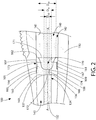
FIG. 2 , a close-up view of area II ofFIG. 1 is illustrated.FIG. 2 illustrates a close-up view of thepartition member 160 within theinternal reservoir 140. As noted above, thepartition member 160 is a structural member that is positioned within theinternal reservoir 140 to separate theinternal reservoir 140 into thestorage chamber 142 and theoverflow chamber 143. Thepartition member 160 is positioned at a fixed axial location within theinternal reservoir 140, which assists with ensuring that all components of the oral care implement 100 are located at the same position each time that the oral care implement is assembled 100. Specifically, by locating thepartition member 160 at a fixed axial location within theinternal reservoir 140 and by fixing the lengths of thewick member 132 andapplicator 130, it can be ensured that all components are at the same position each time the oral care implement 100 is assembled. - In certain embodiments, the
partition member 160 is positioned within theinternal reservoir 140 by an interference fit such that thepartition member 160 is pressed into theinternal reservoir 140 until anouter surface 161 of thepartition member 160 fits snugly against theinner surface 129 of thehandle 110 that defines theinternal reservoir 140. In this manner, thepartition member 160 is static and non-movable within theinternal reservoir 140. In the exemplified embodiment, theouter surface 161 of thepartition member 160 comprises a firstannular projection 107 and a secondannular projection 108. The first and secondannular projections region 109 on theouter surface 161 of thepartition member 160. Thus, theouter surface 161 of thepartition member 160 is a stepped surface. While the first and secondannular projections outer surface 161 of thepartition member 160 are in abutment with theinner surface 129 of thehandle 110, the recessedregion 109 of theouter surface 161 of thepartition member 160 is spaced from theinner surface 129 of thehandle 110 by agap 105. Of course, the invention is not to be so limited by this structural arrangement in all embodiments and in certain other embodiments theouter surface 161 of thepartition member 160 may be a non-stepped surface. - Furthermore, the invention is not to be limited by an interference fit between the
partition member 160 and theinner surface 129 of thehandle 110 in all embodiments, and in certain other embodiments thepartition member 160 may be stationarily positioned within theinternal reservoir 140 by other techniques, such as adhesion, fasteners, threaded engagement, tight-fit assembly, ultrasonic or thermal welding, or a coupling sleeve. Thepartition member 160 can be formed from a variety of different types of materials, including without limitation polypropylene, low and high density polyethylene, thermoplastic elastomer and thermoplastic vulcanizate. Of course, the invention is not to be so limited and materials other than those mentioned herein can be used to form thepartition member 160 in other embodiments. - The
partition member 160 comprises afirst surface 162 facing thestorage member 142 and asecond surface 163 facing theoverflow chamber 163. In the exemplified embodiment, each of the first andsecond surfaces partition member 160 are transverse surfaces. Specifically, each of the first andsecond surfaces partition member 160 are transverse to and oriented at a normal angle relative to the longitudinal axis A-A of thehandle 110. - Furthermore, a
passageway 170 extends through thepartition member 160 from thestorage chamber 142 to theoverflow chamber 143. Thepassageway 170 terminates as afirst opening 171 in thefirst surface 162 of thepartition member 160 and as asecond opening 172 in thesecond surface 163 of thepartition member 160. Thus, theoral care fluid 141 in theinternal reservoir 140 flows from thestorage chamber 142 through thefirst opening 171 in thefirst surface 162 of thepartition member 160, through thepassageway 170 and then through thesecond opening 172 in thesecond surface 163 of thepartition member 160 where it contacts thewick member 132. In the exemplified embodiment, thefirst opening 171 has a diameter DO1, and thesecond opening 172 has a diameter DO2 such that the diameter DO1 of thefirst opening 171 is greater than the diameter DO2 of thesecond opening 172. - The
passageway 170 comprises aninlet section 173 and adelivery section 174. Theinlet section 173 of thepassageway 170 and thedelivery section 174 of thepassageway 170 are in fluid communication with one another, and thedelivery section 174 and theinlet section 173 collectively form theentire passageway 170. Theinlet section 174 comprises thefirst opening 171 and extends from thestorage chamber 142 to thedelivery section 174 and terminates at thefirst opening 171. Thedelivery section 174 comprises thesecond opening 172 and extends from theinlet section 173 to theoverflow chamber 143 and terminates at thesecond opening 172. In the exemplified embodiment, theinlet section 173 has a maximum transverse cross-sectional area that is greater than a maximum transverse cross-sectional area of thedelivery section 174. Thus, thedelivery section 174 is narrower than theinlet section 173 and prevents excess amounts of theoral care fluid 141 from flowing through thedelivery section 174 and into contact with thewick member 132. By being a narrowed section of thepassageway 170, thedelivery section 174 minimizes the amount of theoral care fluid 141 that is able to exit thestorage chamber 142 and reduces the likelihood of overdosing thewick member 132 with theoral care fluid 141. - Conceptually, the
partition member 160 comprises anupper section 165 and anannular sidewall 166 extending from theupper section 165 in a direction towards thestorage chamber 142. Theannular sidewall 166 of thepartition member 160 comprises aninner surface 167 that defines theinlet section 173 of thepassageway 170. In the exemplified embodiment, theinner surface 167 of theannular sidewall 166 of thepartition member 160 is a concave surface facing thestorage chamber 142. Thus the cross-sectional area of theinlet section 173 of thepassageway 170 decreases with distance from thestorage chamber 142. However, the invention is not to be so limited in all embodiments and in certain other embodiments the cross-sectional area of theinlet section 173 of the passageway can be constant. - Furthermore, the
upper section 165 of thepartition member 160 comprises aninner surface 168 that defines thedelivery section 174 of thepassageway 170. In the exemplified embodiment, the cross-sectional area of thedelivery section 174 of thepassageway 170 is constant. However, the invention is not to be so limited in all embodiments and in certain other embodiments the cross-sectional area of thedelivery section 174 of thepassageway 170 may increase and/or decrease with distance from theinlet section 173 of thepassageway 170. Specifically, in certain embodiments the cross-sectional area of thedelivery section 174 of thepassageway 170 may decrease with distance from theinlet section 173 of thepassageway 170 in order to further limit the amount of theoral care fluid 141 that is able to contact thewick member 132. - The
wick member 132 extends from theapplicator 130, through thechannel 135 and into theoverflow chamber 143. More specifically, thesecond end 134 of thewick member 132 terminates in anend surface 136 that abuts thesecond surface 163 of thepartition member 160. Due to the abutment of theend surface 136 of thesecond end 134 of thewick member 132 against thesecond surface 163 of thepartition member 160, axial movement of thewick member 132 in a first axial direction towards thestorage chamber 142 is prohibited. - In the exemplified embodiment, the
end surface 136 of thesecond end 134 of thewick member 132 abuts against thesecond surface 163 of thepartition member 160 at a location such that theend surface 136 of thesecond end 134 of thewick member 132 covers thesecond opening 172 in thesecond surface 163 of thepartition member 160. As a result, as theoral care fluid 141 flows through thepassageway 170 and through thesecond opening 172, theoral care fluid 141 comes directly into contact with thewick member 132. Due to the material that forms thewick member 132 as discussed above, theoral care fluid 141 is then soaked up by thewick member 132 and flows along thewick member 132 towards theapplicator 130 via capillary action where theoral care fluid 141 is dispensed onto a user's tongue, gums, teeth and other oral surfaces during use of the oral care implement 100. In the exemplified embodiment, theend surface 136 of thesecond end 134 of thewick member 132 is a transverse surface. However, the invention is not to be so limited in all embodiments as will be discussed in more detail below with reference toFIG. 4 . - Although the exemplified embodiment illustrates the
end surface 136 of thesecond end 134 of thewick member 132 covering thesecond opening 172, in alternate embodiments theend surface 136 of thesecond end 134 of thewick member 132 may not cover thesecond opening 172. Specifically, in other embodiments theend surface 136 of thesecond end 134 of thewick member 132 may abut thesecond surface 163 of thepartition member 160 while being positioned adjacent to thesecond opening 172. In such embodiments, theoral care fluid 141 will flow through thesecond opening 172 and into theoverflow chamber 143 where it will contact thewick member 132. - The
end surface 136 of thesecond end 134 of thewick member 132 has anouter perimeter 137 having a diameter Dw. In the exemplified embodiment, the diameter Dw of theend surface 136 of thesecond end 134 of thewick member 132 is greater than the diameter DO2 of thesecond opening 172. Thus, in this embodiment theend surface 136 of thesecond end 134 of thewick member 132 is prevented from penetrating through thesecond opening 172 and into thedelivery section 174 of thepassageway 170 because theend surface 136 of thesecond end 134 of thewick member 132 abuts against thesecond surface 163 of thepartition member 160. Due to the diameter Dw of theouter perimeter 137 of theend surface 136 of thesecond end 134 of thewick member 132 being greater than the diameter DO2 of thesecond opening 172 and due to the relative positioning of thewick member 132 relative to thesecond opening 172, theouter perimeter 137 of theend surface 136 of thesecond end 134 of thewick member 132 surrounds thesecond opening 172 in the exemplified embodiment. - In the exemplified embodiment, the diameter DO1 of the
first opening 171 in thefirst surface 162 of thepartition member 160 is greater than the diameter Dw of theouter perimeter 137 of theend surface 136 of thesecond end 134 of thewick member 132. However, the invention is not to be so limited and in certain other embodiments the diameter DO1 of thefirst opening 171 in thefirst surface 162 of thepartition member 160 can be equal to or less than the diameter Dw of theouter perimeter 137 of theend surface 136 of thesecond end 134 of thewick member 132. Furthermore, in the exemplified embodiment thewick member 132 has a constant diameter Dw. However, the invention is not to be so limited and in certain embodiments the diameter Dw of thewick member 132 may increase or decrease from thesecond end 134 of the wick member to thefirst end 133 of thewick member 132. - Referring now to
FIG. 3 , an alternative embodiment of a portion of an oral care implement 100A will be discussed in accordance with the present invention. The embodiment exemplified inFIG. 3 is similar to the embodiment exemplified inFIG. 2 with the exception of the shape of thepartition member 160A and the relative positioning between thepartition member 160A and thewick member 132A. Thus, components of the oral care implement 100A that are similar to or the same as components of the oral care implement 100 described above will not be described herein below in the interest of brevity. Furthermore, components of the oral care implement 100A will be numbered similarly to the same components of the oral care implement 100 except that the suffix "A" will be used. Thus, it should be understood that those components of the oral care implement 100A that are numbered but not described herein below have a similar function and/or structure to the similar component illustrated inFIGS. 1 and2 and described above. - The
partition member 160A comprises afirst surface 162A and asecond surface 163A. Similar to the embodiment discussed above, thesecond surface 163A of thepartition member 160A is a transverse surface. However, inFIG. 3 the transversesecond surface 163A is a stepped surface. Specifically, the transversesecond surface 163A comprises anupper surface 198A and a recessedsurface 199A. Two opposing riser surfaces 196A, 197A extend from opposing ends of the recessedsurface 199A to theupper surface 198A and form an annular shoulder. Asocket 195A is formed between the opposing riser surfaces 196A, 197A having the recessedsurface 199A as a floor of thesocket 195A. In the exemplified embodiment, the width of the recessedsurface 199A is substantially equal to the diameter Dw of thewick member 132A. However, in certain other embodiments the width of the recessedsurface 199A may be slightly larger than the diameter Dw of thewick member 132A. - The
partition member 160A comprises afirst opening 171A in thefirst surface 162A of thepartition member 160A and asecond opening 172A in thesecond surface 163A of thepartition member 160A. Thewick member 132A comprises asecond end 134A that terminates in anend surface 136A. In the exemplified embodiment, theend surface 136A of thesecond end 134A of thewick member 132A protrudes through thesecond opening 172A in thesecond surface 163A of thepartition member 160A and abuts the recessedsurface 199A of thesecond surface 163A of thepartition member 160A. In the exemplified embodiment, thewick member 132A fits snugly within thesocket 195A such that theouter surface 194A of thesecond end 134A of thewick member 132A is in contact with the riser surfaces 196A, 197A. However, in embodiments whereby the recessedsurface 199A has a greater width than the width Dw of thewick member 132A, thewick member 132A may not be in contact with both of the riser surfaces 196A, 197A. - The
socket 195A further facilitates proper positioning of thewick member 132A to ensure that theend surface 136A of thesecond end 134A of thewick member 132A is in fluid communication with thedelivery section 174A of thepassageway 170A that extends through thepartition member 160A. Furthermore, theend surface 136A of thesecond end 134A of thewick member 132A abuts thesecond surface 163A of thepartition member 160A to prohibit axial movement of thewick member 132A in a first axial direction, the first axial direction being in a direction towards thestorage chamber 142A of theinternal reservoir 140A in the exemplified embodiment. Moreover, due to the positioning of theend surface 136A of thesecond end 134A of thewick member 132A relative to thedelivery section 174A of thepassageway 170A, all of theoral care fluid 141A flowing through thepassageway 170A from theinlet section 173A to thedelivery section 174A and towards thesecond opening 172A in thesecond surface 163A of thepartition 160A will come into contact with thewick member 132A. - Referring now to
FIG. 4 , another alternative embodiment of a portion of an oral care implement 100B will be discussed in accordance with the present invention. The embodiment exemplified inFIG. 4 is similar to the embodiment exemplified inFIG. 2 with the exception of the shape of thepartition member 160B and the relative positioning between thepartition member 160B and thewick member 132B. Thus, components of the oral care implement 100B that are similar to or the same as components of the oral care implement 100 described above will not be described herein below in the interest of brevity. Furthermore, components of the oral care implement 100B will be numbered similarly to the same components of the oral care implement 100 except that the suffix "B" will be used. Thus, it should be understood that those components of the oral care implement 100B that are numbered but not described herein below have a similar function and/or structure to the similar component illustrated inFIGS. 1 and2 and described above. - In the embodiment exemplified in
FIG. 4 , thepartition member 160B has a structure that is substantially similar to thepartition member 160 illustrated inFIGS. 1 and2 . Specifically, thepartition member 160B has afirst surface 162B and asecond surface 163B. Apassageway 170B is formed through thepartition member 160B. Afirst opening 171B is formed into thefirst surface 162B of thepartition member 160B and asecond opening 172B is formed into thesecond surface 163B of thepartition member 160B. - The
wick member 132B comprises asecond end 134B that terminates in anend surface 136B that abuts thesecond surface 163B of thepartition member 160B. In the exemplified embodiment, theend surface 136B of thesecond end 134B of thewick member 132B is conical. Thus, although a portion of theend surface 136B of thesecond end 134B of thewick member 132B is able to penetrate through thesecond opening 172B in thesecond surface 163B of thepartition member 160B, a portion of the end surface 13B of thesecond end 134B of thewick member 132B still abuts against thesecond surface 163B of thepartition member 160B. In this manner, thewick member 132B is prohibited from axial movement in a first axial direction towards thestorage chamber 142B due to theend surface 136B of thesecond end 134B of thewick member 132B abutting against thesecond surface 163B of thepartition member 160B. - The invention and inventive concepts described herein include various combinations of the embodiments illustrated in
FIGS. 2 ,3 and4 as would be understood by persons of ordinary skill in the art. For example, thewick member 132B having theconical end surface 136B ofFIG. 4 can be used with thepartition member 160 illustrated inFIG. 2 . - As used throughout, ranges are used as shorthand for describing each and every value that is within the range. Any value within the range can be selected as the terminus of the range. In the event of a conflict in a definition in the present disclosure and that of a cited reference, the present disclosure controls.
Claims (15)
- A toothbrush (100) comprising:a handle (110) extending along a longitudinal axis (A) and having an internal reservoir (140) containing an oral care fluid (141);a head (120) coupled to the handle (110) and having a plurality of tooth cleaning elements (123);an applicator (130) located on the head (120);a partition member (160) positioned within the internal reservoir (140) that divides the internal reservoir (140) into a storage chamber (142) and an overflow chamber (143), the partition member (140) comprising a first surface (162) facing the storage chamber (142) and a second surface (163) facing the overflow chamber (143);a passageway (170) extending through the partition member (160) from the storage chamber (142) to the overflow chamber (143), the passageway (170) terminating as a first opening (171) in the first surface (162) of the partition member (160) and as a second opening (172) in the second surface (163) of the partition member (160); anda wick member (132) having a first end (133) in fluid communication with the applicator (130) and a second end (134); characterized in that the second end (134) terminates in an end surface (136) that abuts the second surface (163) of the partition member (160) without penetrating the second opening (172) of the partition member (160) to prohibit axial movement of the wick member (132) in a first axial direction.
- The toothbrush (100) according to claim 1 wherein the tooth cleaning elements (123) extend from a front surface (121) of the head (120) and the applicator (130) is located on a rear surface (122) of the head (120).
- The toothbrush (100) according to claim 2 further comprising a channel (135) extending from the overflow chamber (143) to an opening (139) on the rear surface (122) of the head (120), a portion of the wick member (132) located within the channel (135) and the applicator (130) exposed through the opening (139) on the rear surface (122) of the head (120).
- The toothbrush (100) according to any one of claims I to 3 wherein the second surface (163) of the partition member (160) is a transverse surface.
- The toothbrush (100) according to claim 4 wherein the second surface (163) of the partition member (160) comprises an upper surface (198A) and a recessed surface (199A); and wherein the end surface (136) of the second end (134) of the wick member (132) abuts the recessed surface (199A) of the second surface (163) of the partition member (160).
- The toothbrush (100) according to any one of claims 1 to 5 wherein the end surface (136) of the second end (134) of the wick member (132) is conical.
- The toothbrush (100) according to any one of claims 1 to 6 wherein the end surface (136) of the second end (134) of the wick member (132) has a diameter Dw and wherein the second opening (172) of the passageway (170) has a diameter D02, the diameter Dw of the end surface (136) of the second end (134) of the wick member (132) being greater than the diameter D02 of the second opening (172).
- The toothbrush (100) according to claim 7 wherein the first opening (171) of the passageway (170) has a diameter D01, the diameter D01 of the first opening (171) of the passageway (170) being greater than the diameter D02 of the second opening (172) of the passageway (170).
- The toothbrush (100) according to any one of claims 1 to 8 wherein the end surface (136) of the second end (134) of the wick member (132) has an outer perimeter that surrounds the second opening (172).
- The toothbrush (100) according to any one of claims 1 to 9 wherein the partition member (160) is positioned within the internal reservoir (140) at a fixed axial location.
- The toothbrush (100) according to any one of claims 1 to 10 wherein the first axial direction is towards the storage chamber (142).
- The toothbrush (100) according to any one of claims 1 to 11 wherein the material that forms the partition member (160) is selected from the group consisting of polypropylene, low density polyethylene, high density polyethylene, thermoplastic elastomer and thermoplastic vulcanizate.
- The toothbrush (100) according to any one of claims 1 to 12 wherein the oral care fluid (141) in the internal reservoir (140) is delivered to the applicator (130) solely by capillary action through the wick member (132).
- The toothbrush (100) according to any one of claims 1 to 13 wherein the wick member (132) comprises a first portion having a first capillarity and a second portion having a second capillarity, the first and second capillarities being different.
- The toothbrush (100) according to any one of claims 1 to 14 wherein the wick member (132) is integrally formed with the applicator (130).
Applications Claiming Priority (2)
| Application Number | Priority Date | Filing Date | Title |
|---|---|---|---|
| US201261719016P | 2012-10-26 | 2012-10-26 | |
| PCT/US2013/063678 WO2014066021A2 (en) | 2012-10-26 | 2013-10-07 | Oral care implement |
Publications (2)
| Publication Number | Publication Date |
|---|---|
| EP2911554A2 EP2911554A2 (en) | 2015-09-02 |
| EP2911554B1 true EP2911554B1 (en) | 2017-04-26 |
Family
ID=49356548
Family Applications (1)
| Application Number | Title | Priority Date | Filing Date |
|---|---|---|---|
| EP13776938.6A Active EP2911554B1 (en) | 2012-10-26 | 2013-10-07 | Oral care implement |
Country Status (14)
| Country | Link |
|---|---|
| US (2) | US9554641B2 (en) |
| EP (1) | EP2911554B1 (en) |
| JP (1) | JP2015532877A (en) |
| KR (1) | KR20150080492A (en) |
| CN (1) | CN104768421B (en) |
| AU (1) | AU2013335145B2 (en) |
| BR (1) | BR112015009125A2 (en) |
| CA (1) | CA2885057C (en) |
| IN (1) | IN2015DN03043A (en) |
| MX (1) | MX357206B (en) |
| PH (1) | PH12015500886A1 (en) |
| RU (1) | RU2601930C1 (en) |
| TW (1) | TWI540984B (en) |
| WO (1) | WO2014066021A2 (en) |
Families Citing this family (16)
| Publication number | Priority date | Publication date | Assignee | Title |
|---|---|---|---|---|
| WO2012105961A1 (en) * | 2011-02-01 | 2012-08-09 | Colgate-Palmolive Company | Oral care implement with fluid applicator and method of assembling the same |
| MX338787B (en) | 2011-03-28 | 2016-05-02 | Colgate Palmolive Co | Toothbrush having oral care fluid delivery. |
| WO2012148423A1 (en) * | 2011-04-29 | 2012-11-01 | Colgate-Palmolive Company | Oral care implement having visual indicator of depletion of a fluid |
| AU2013406764B2 (en) | 2013-12-05 | 2016-12-22 | Colgate-Palmolive Company | Oral care implement with cover member |
| TWI529391B (en) | 2015-01-22 | 2016-04-11 | 國立臺灣大學 | System and method for using photoacoustic effect |
| US10681976B2 (en) * | 2015-12-28 | 2020-06-16 | Colgate-Palmolive Company | Brush with fluid delivery |
| US10179038B2 (en) * | 2015-12-30 | 2019-01-15 | Colgate-Palmolive Company | Oral care device with sacrificial electrode |
| ITUA201699881U1 (en) * | 2016-04-18 | 2017-10-18 | Dambrogio Enzo | Toothbrush with tank under the bristles. |
| US20190075918A1 (en) * | 2017-09-08 | 2019-03-14 | Innotech Appliance Limited | Bristle tuft assembly and a toothbrush device |
| GB2575659B (en) * | 2018-07-18 | 2020-11-25 | Dyson Technology Ltd | Dental appliance with fluid delivery system |
| US11484112B2 (en) * | 2018-11-13 | 2022-11-01 | Colgate-Palmolive Company | Method of whitening teeth |
| US10638832B1 (en) | 2018-11-13 | 2020-05-05 | Colgate-Palmolive Company | Fluid dispensing oral care implement |
| US10849422B2 (en) | 2018-11-13 | 2020-12-01 | Colgate-Palmolive Company | Method of sanitizing a toothbrush |
| US11224284B2 (en) | 2020-02-18 | 2022-01-18 | Colgate-Palmolive Company | Personal care system and fluid supply system thereof |
| EP4161433A2 (en) | 2020-06-05 | 2023-04-12 | Giovanni CARRAZZA | Device for horal hygiene |
| IT202000013372A1 (en) | 2020-06-05 | 2021-12-05 | Giovanni Carrazza | DEVICE FOR ORAL HYGIENE |
Family Cites Families (239)
| Publication number | Priority date | Publication date | Assignee | Title |
|---|---|---|---|---|
| US510482A (en) | 1893-12-12 | Tames f | ||
| US1798081A (en) | 1928-06-21 | 1931-03-24 | Jr Cornelius Gordyn | Self-disinfecting brush |
| US1973212A (en) | 1932-05-28 | 1934-09-11 | Edwin W Krueger | Toothbrush |
| US2154209A (en) | 1937-06-04 | 1939-04-11 | Kohn Jack | Combination tooth brush and sipper |
| US2416684A (en) | 1943-09-04 | 1947-03-04 | George Ulvick | Fountain brush |
| US2573201A (en) | 1945-11-13 | 1951-10-30 | James F Kelley | Type cleaning brush |
| US2594721A (en) | 1949-04-09 | 1952-04-29 | Fredrick E Beebe | Applicator for dye and the like |
| DE914602C (en) * | 1952-06-20 | 1954-08-02 | Heinrich Magel | Toothbrush with a hollow handle to hold a replaceable ampoule |
| US2739328A (en) | 1955-01-12 | 1956-03-27 | Dorothy K Bernier | Soap brush |
| US2964012A (en) * | 1956-04-05 | 1960-12-13 | Kahn David Inc | Writing instrument |
| GB842965A (en) | 1957-10-15 | 1960-08-04 | George Johnstone Milligan | Improvements in and relating to applicators for liquid medicaments |
| US2968827A (en) * | 1958-01-23 | 1961-01-24 | Lawsine Leo | Tooth cleaning and gum massaging device |
| US3369543A (en) | 1965-03-30 | 1968-02-20 | Deron Inc | Medicinal applicators |
| US3459483A (en) * | 1967-03-01 | 1969-08-05 | Gen Mills Inc | Marking device |
| US3685080A (en) | 1969-08-28 | 1972-08-22 | Huebner Otto | Mechanically powered toothbrush |
| US3810479A (en) | 1972-10-17 | 1974-05-14 | Colgate Palmolive Co | Toothbrush having antimicrobial means |
| JPS5651B2 (en) | 1973-03-21 | 1981-01-06 | ||
| US3910706A (en) | 1974-01-07 | 1975-10-07 | Trisa Buerstenfabrik Ag | Cartridge for liquid or pasty dentifrice |
| US3903888A (en) | 1974-03-11 | 1975-09-09 | Minnesota Mining & Mfg | Time-delay metering dispenser |
| US3902510A (en) | 1974-08-16 | 1975-09-02 | Lawrence Peska Ass Inc | Dental floss device |
| US3936200A (en) | 1974-09-16 | 1976-02-03 | Rourke James L O | Toothbrush with dentifrice attachment |
| US4060870A (en) | 1975-12-23 | 1977-12-06 | Anthony Cannarella | Toothpaste administering automatic toothbrush |
| US4124316A (en) | 1976-01-09 | 1978-11-07 | Rourke James L O | Toothbrush with dentifrice attachment |
| US4023580A (en) | 1976-04-14 | 1977-05-17 | Lawrence Peska Associates, Inc. | Plaque marker toothbrush kit |
| NO146799L (en) | 1976-06-08 | 1900-01-01 | ||
| US4088412A (en) | 1976-08-24 | 1978-05-09 | Luigi Del Bon | Fountain brush |
| US4181997A (en) * | 1978-04-21 | 1980-01-08 | Rourke James L O | Water-powered toothbrush with dentifrice attachment |
| FR2452277A1 (en) | 1979-03-30 | 1980-10-24 | Grisoni Nicole | Retractable toothpick - passes on extension through magazine containing disinfectant liquid |
| US4304245A (en) | 1980-06-16 | 1981-12-08 | Lichfield William H | Therapeutic toothpick |
| JPS601018B2 (en) | 1980-11-18 | 1985-01-11 | 昭和薬品化工株式会社 | Plaque removal and gingival pine surge equipment |
| US5834871A (en) | 1996-08-05 | 1998-11-10 | Puskas; William L. | Apparatus and methods for cleaning and/or processing delicate parts |
| DE3113450C1 (en) | 1981-04-03 | 1982-10-07 | Blendax-Werke R. Schneider Gmbh & Co, 6500 Mainz | Mouthwash concentrate |
| DE3202435C1 (en) | 1982-01-26 | 1983-11-03 | Fa. A.W. Faber-Castell, 8504 Stein | Cosmetic cleaning device |
| US4486109A (en) * | 1982-02-19 | 1984-12-04 | Oral Ease Inc. | Toothbrush assembly combining replaceable brush assembly with massaging device |
| US4608968A (en) * | 1982-02-19 | 1986-09-02 | Oral Ease Inc. | Gum massaging device with internal dispenser |
| EP0092359A3 (en) | 1982-04-21 | 1985-08-21 | BOLTON, Terence William | Liquid dispensing and atomizing device |
| US4521128A (en) | 1982-04-21 | 1985-06-04 | Neal Chester L O | Disposable toothbrush with cap |
| JPS58225029A (en) | 1982-06-21 | 1983-12-27 | Showa Yakuhin Kako Kk | Simple diagnostic method for tooth decay and device therefor |
| US4543679A (en) | 1982-10-08 | 1985-10-01 | Oral Ease Inc. | Toothbrush assembly combining a handle with a replaceable brush assembly and a replaceable oral hygiene device |
| US4585018A (en) | 1982-12-06 | 1986-04-29 | Texas Romec, Inc. | Liquid dispensing comb |
| US4538631A (en) | 1983-04-29 | 1985-09-03 | Prince Mary F | Oral hygiene instrument |
| US4509541A (en) | 1983-06-24 | 1985-04-09 | William D. Manciocchi, Jr. | Antiseptic toothpick |
| US4583563A (en) * | 1983-08-12 | 1986-04-22 | Turner Burton S | Combined toothbrush and toothpaste dispenser |
| JPS60129148U (en) | 1984-02-08 | 1985-08-30 | 富士通株式会社 | Socket for semiconductor integrated circuit |
| US4753249A (en) | 1984-07-19 | 1988-06-28 | Davstar Industries, Inc. | Urinometer and patient record combination |
| US4716035A (en) | 1985-05-24 | 1987-12-29 | The Procter & Gamble Company | Oral compositions and methods for treating gingivitis |
| US4990329A (en) | 1985-05-24 | 1991-02-05 | The Procter & Gamble Company | Composition for treating oral diseases |
| DE3614230C1 (en) | 1986-04-26 | 1987-08-27 | Pelikan Ag | Method for producing writing wicks and device for carrying out the method |
| ZA872857B (en) | 1986-05-02 | 1987-11-25 | Warner Lambert Co | Composition and method to inhibit the growth of organisms by the use of bis-biguanido hexanes and essential oil mixture combinations |
| DE3622234A1 (en) | 1986-07-02 | 1988-01-07 | Henkel Kgaa | DISPENSER FOR HAIR-COSMETIC PRODUCTS |
| JPH0342805Y2 (en) | 1987-05-30 | 1991-09-09 | ||
| JPS63300708A (en) | 1987-05-30 | 1988-12-07 | 益山興業株式会社 | Cosmetics applicator |
| JPH0197406A (en) | 1987-06-22 | 1989-04-14 | Kao Corp | Toothbrush containing toothpaste therein |
| US5017036A (en) | 1987-10-13 | 1991-05-21 | Gerda Vidovic | Toothbrush with absorbent pad |
| JPH0694237B2 (en) | 1988-08-04 | 1994-11-24 | 蔵合 正博 | Polygonal pen |
| FR2633498B1 (en) | 1988-06-30 | 1992-03-06 | Oreal | APPLICATOR ASSEMBLY FOR MAKING EYELASHES COMPRISING A MASCARA BREAD AND A HUMIDIFIED DISPENSING ELEMENT |
| US5000193A (en) | 1988-08-01 | 1991-03-19 | Adi Diagnostics Inc. | Medical swab device |
| US5066155A (en) | 1988-08-29 | 1991-11-19 | English Philip H | Toothbrush and paste dispenser |
| DE3832520A1 (en) | 1988-09-24 | 1990-04-05 | Schiffer Fa M & C | Method and device for producing brushes, in particular brushes for hygiene requirements, such as toothbrushes |
| US5098297A (en) | 1988-10-04 | 1992-03-24 | John O. Butler Company | Apparatus for application of a tooth desensitizing composition |
| JPH02152405A (en) | 1988-12-02 | 1990-06-12 | Kao Corp | Tooth-paste agent containing tooth brush |
| US4992276A (en) | 1988-12-14 | 1991-02-12 | Warner-Lambert Company | Antiseptic compositions containing hexahydro-5-pyrimidinamine compounds and thymol and methods for preparing same |
| DE3912411C1 (en) | 1989-04-15 | 1990-09-13 | Dataprint Datendrucksysteme R. Kaufmann Kg, 2000 Hamburg, De | |
| DE8914353U1 (en) | 1989-12-06 | 1990-02-15 | Schwan Stabilo Schwanhaeusser | |
| US5033898A (en) * | 1990-04-23 | 1991-07-23 | Williams Curtis C | Toothbrush with sponge flow control |
| US5352052A (en) | 1990-05-15 | 1994-10-04 | Dataprint Datendrucksysteme R. Kaufmann Kg | Device for applying writing, drawing, printing and painting fluids onto a surface |
| US5088627A (en) | 1990-07-25 | 1992-02-18 | Wheaton Industries | Multi-chamber package for mixing and dispensing |
| US5062728A (en) * | 1990-07-31 | 1991-11-05 | Youti Kuo | Dentifrice dispensing toothbrush with replaceable cartridge |
| US5407287A (en) | 1990-10-01 | 1995-04-18 | John C. Braun | Toothbrush with self-contained toothpaste dispenser |
| GB9024890D0 (en) | 1990-11-15 | 1991-01-02 | Stewart Timothy N | Toothbrushes |
| JP3243528B2 (en) | 1990-12-13 | 2002-01-07 | コニンクリュケ・フィリップス・エレクトロニクス・エヌ・フェー | Toothpaste / drug distribution type toothbrush |
| US5454658A (en) * | 1991-01-31 | 1995-10-03 | Pentel Kabushiki Kaisha | Rear end knocking type liquid discharge apparatus |
| US6089776A (en) | 1991-05-14 | 2000-07-18 | Kaufmann; Rainer | Fluid dispensing utensil |
| DE4115685C3 (en) | 1991-05-14 | 2001-07-05 | Dataprint Datendrucksysteme R | Writing instrument with writing fluid freely contained in a container |
| US5346324A (en) | 1991-09-19 | 1994-09-13 | Youti Kuo | Dentifrice dispensing toothbrush with replaceable cartridge |
| DE4139141A1 (en) | 1991-11-28 | 1993-06-03 | Innova Tec Gmbh Berlin Entwick | Writing tool for broad application of writing fluid - has wedge shaped point with wedge surfaces and writing edge formed by wedge vertex |
| DE4237616A1 (en) | 1992-11-06 | 1994-05-11 | Merz & Krell | Capillary-ink storage system |
| FR2701818B1 (en) | 1993-02-22 | 1995-06-16 | Oreal | APPLICATOR. |
| DE4306214A1 (en) | 1993-02-27 | 1994-09-01 | Geka Brush Georg Karl Gmbh | Brush with bristles fixed between twisted wire sections |
| US5283056A (en) | 1993-07-01 | 1994-02-01 | International Flavors & Fragrances Inc. | Transparent oil-in-water microemulsion flavor or fragrance concentrate, process for preparing same, mouthwash or perfume composition containing said transparent microemulsion concentrate, and process for preparing same |
| US6322268B1 (en) | 1993-11-12 | 2001-11-27 | Avery Dennison Corporation | Efficient fluid dispensing utensil |
| US6416242B1 (en) * | 1993-11-12 | 2002-07-09 | Dataprint R. Kaufmann Gmbh | Efficient fluid dispensing utensil |
| US5393153A (en) * | 1993-12-01 | 1995-02-28 | Corporation Roch-Jean Bouthillier Et Fils Inc. | Toothpaste dispenser |
| JPH09510186A (en) | 1993-12-22 | 1997-10-14 | ザ、プロクター、エンド、ギャンブル、カンパニー | Concentrated mouthrinse for efficient delivery of antimicrobial agents |
| US5463792A (en) | 1993-12-27 | 1995-11-07 | Hogan; James E. | Aspirating tooth brush |
| US5403299A (en) | 1994-01-18 | 1995-04-04 | Hollister Incorporated | Flush-interval indicator for soluble pouches |
| NL9400631A (en) | 1994-04-20 | 1995-12-01 | Wilhelmina Walthera Johanna Co | Toothbrush, comprising holder and brush part |
| US5490736A (en) | 1994-09-08 | 1996-02-13 | Habley Medical Technology Corporation | Stylus applicator for a rehydrated multi-constituent medication |
| US5509742A (en) | 1995-03-23 | 1996-04-23 | Balzarini; Grace M. | Mascara applicator and mascara removal device |
| DE19529865C2 (en) | 1995-08-14 | 2002-02-28 | Kaufmann R Dataprint | Device for applying liquids to a base by means of an application element |
| US5611687A (en) | 1995-11-06 | 1997-03-18 | Dental Concepts Inc. | Oral hygiene delivery system |
| JPH09215524A (en) | 1996-02-08 | 1997-08-19 | Eiko Chiba | Toothbrush |
| US5829976A (en) | 1996-04-12 | 1998-11-03 | Green; Warren F. | Medicament-containing interproximal dental brush |
| US5910122A (en) | 1996-06-04 | 1999-06-08 | Americare Health Scan Inc. | Saliva collector with an aspirating pipette |
| US5842248A (en) | 1996-06-07 | 1998-12-01 | Van Grol; Derrick K. | Toothbrush with a catch basin and drain |
| JP3625587B2 (en) * | 1996-06-17 | 2005-03-02 | リコーエレメックス株式会社 | Toothbrush device with liquid supply / drainage function |
| US5909845A (en) | 1996-06-28 | 1999-06-08 | S. C. Johnson & Son, Inc. | Wick-based liquid emanation system with child-resistant overcap |
| RU2105519C1 (en) | 1996-10-17 | 1998-02-27 | Евгений Петрович Еремин | Toothbrush |
| US5769553A (en) | 1996-11-08 | 1998-06-23 | Chaudhri; Aslam | Toothbrush |
| DE19706967C1 (en) | 1997-02-21 | 1998-09-03 | Kaufmann R Dataprint | Liquid regulator for supplying a consumer with liquid from a liquid supply |
| GB2326086B (en) | 1997-06-12 | 2002-01-09 | Eitan Rivlin | Toothbrush with reservoir for dentrifice |
| US5865195A (en) | 1997-07-03 | 1999-02-02 | Carter; Theresa | Oral hygiene system |
| AU3904797A (en) | 1997-07-31 | 1999-02-22 | Michael R. Anderson | Tooth whitening system |
| US5875798A (en) | 1997-09-23 | 1999-03-02 | Advanced Medical Instruments, Inc. | Therapeutic toothpick for treating oral and systemic diseases |
| US6039489A (en) | 1997-11-25 | 2000-03-21 | Icp Corporation | Paste dispensing brush |
| FR2777459A1 (en) | 1998-04-20 | 1999-10-22 | Francois Darne | Novel concentrated toothpaste having antibacterial and anti-caries activity |
| CN2343878Y (en) | 1998-08-17 | 1999-10-20 | 孙继中 | Toothbrush with liquid toothpaste |
| US6203320B1 (en) | 1998-12-22 | 2001-03-20 | Unilever Home & Personal Care Usa, Division Of Conopco, Inc. | Electric toothbrush and method combining bristle and pulsed liquid irrigation cleansing to oral cavity |
| US6205611B1 (en) | 1999-04-01 | 2001-03-27 | Onesimo Vigil | Tooth and gum cleaning tool |
| US6110888A (en) | 1999-05-10 | 2000-08-29 | Takasago International Corporation | Substituted phenols as fragrance, flavor and antimicrobial compounds |
| US6533734B1 (en) | 1999-06-11 | 2003-03-18 | The Board Of Trustees Of The University Of Illinois | Time-integrated sampler of bodily fluid |
| US6244777B1 (en) | 1999-06-23 | 2001-06-12 | The Global Corporation | One-use toothbrush assembly with external plug for releasing toothpaste from the interior, and method for using the same |
| US6276860B1 (en) * | 1999-06-29 | 2001-08-21 | Mitsubishi Pencil Kabushiki Kaisha | Liquid applicator |
| US6378529B1 (en) | 1999-06-30 | 2002-04-30 | Juan Carlos Clemente Marco | Application tooth for the hair and/or scalp treatment |
| US6082999A (en) | 1999-07-27 | 2000-07-04 | Tcherny; Iosif | Interdental device and container |
| US6331088B2 (en) | 1999-09-16 | 2001-12-18 | Zena Elizabeth Owens | Toothbrush with multiple pumping systems |
| US6669387B2 (en) | 1999-10-08 | 2003-12-30 | The Procter & Gamble Company | Distributing substance onto a target surface |
| US7255506B2 (en) | 2000-06-02 | 2007-08-14 | The Procter & Gamble Company | Semi-enclosed applicator for distributing a substance onto a target surface |
| US7179007B2 (en) | 1999-10-08 | 2007-02-20 | The Procter & Gamble Company | Semi-enclosed applicators for distributing a substance onto a target surface |
| DE19949671A1 (en) | 1999-10-14 | 2001-04-19 | Coronet Werke Gmbh | Brush, especially toothbrush |
| ES2393106T3 (en) | 1999-10-19 | 2012-12-18 | Trisa Holding Ag | Toothbrush |
| US6541042B1 (en) | 1999-10-27 | 2003-04-01 | Bogar Ag | Therapeutically effective combination |
| US6206600B1 (en) | 1999-11-18 | 2001-03-27 | Dorothy J. Rosenberg | Combination toothbrush and toothpaste dispenser |
| KR200183429Y1 (en) | 1999-12-16 | 2000-05-15 | 홍영근 | Electric toothbrush |
| DE60118348T2 (en) | 2000-02-23 | 2006-08-24 | Ciba Speciality Chemicals Holding Inc. | USE OF PHENYLETHYLAMINE DERIVATIVES FOR ANTIMICROBIAL TREATMENT OF SURFACES |
| CA2403819A1 (en) * | 2000-03-22 | 2002-09-20 | Hisashi Iida | Writing implement |
| US6345405B1 (en) | 2000-04-10 | 2002-02-12 | Rickie Brackin | Two-in-one toothbrush |
| EP1289775B1 (en) | 2000-05-15 | 2006-01-11 | Ashraf Mahfouz Abbas | A fluid applicator instrument |
| DE10035214A1 (en) | 2000-07-20 | 2002-02-28 | Schmidt Corinna | Combined toothbrush and toothpaste dispenser with special compressible material used for both parts to permit one-handed use |
| US6434773B1 (en) | 2000-08-28 | 2002-08-20 | Youti Kuo | Dentifrice dispensing electrical toothbrush with snap-on dual brush unit |
| US6418940B1 (en) | 2000-10-17 | 2002-07-16 | Iosif Tcherny | Interdental device and container |
| US6371674B1 (en) | 2000-11-06 | 2002-04-16 | Sharon Lerner | Plaque disclosing agent dispensing toothbrush |
| US6497859B1 (en) | 2000-11-17 | 2002-12-24 | Noville Inc. | Cooling agents, pharmaceutical compositions having cooling agents and processes for making and using same |
| US6648641B1 (en) | 2000-11-22 | 2003-11-18 | The Procter & Gamble Company | Apparatus, method and product for treating teeth |
| WO2002051284A2 (en) | 2000-12-26 | 2002-07-04 | Avon Products, Inc. | Applicator brushes and method for using same |
| US6623698B2 (en) | 2001-03-12 | 2003-09-23 | Youti Kuo | Saliva-monitoring biosensor electrical toothbrush |
| JP4149376B2 (en) | 2001-05-17 | 2008-09-10 | フェールグクレーマン・アクチボラゲット | Sampling apparatus and method for obtaining a sample of a body material |
| US6440087B1 (en) | 2001-05-25 | 2002-08-27 | Choicepoint Asset Co. | Oral fluid collection device and collection method |
| US6637965B1 (en) | 2001-06-22 | 2003-10-28 | Avery Dennison Corporation | Writing instrument having a reservoir between a tip and a capillary storage |
| DE10130298A1 (en) | 2001-06-22 | 2003-01-23 | Nutrinova Gmbh | Antimicrobial acesulfame complexes, process for their preparation and their use |
| US20040255416A1 (en) | 2003-06-20 | 2004-12-23 | Hohlbein Douglas J. | Toothbrush with tongue cleaning member |
| US7143462B2 (en) | 2002-09-20 | 2006-12-05 | Colgate-Palmolive Company | Oral care implement |
| JP4681159B2 (en) | 2001-07-10 | 2011-05-11 | ホーユー株式会社 | Hair cosmetic applicator |
| CN1248872C (en) * | 2001-08-24 | 2006-04-05 | 三菱铅笔株式会社 | Writing implement |
| US20030053938A1 (en) | 2001-09-19 | 2003-03-20 | Becton, Dickinson And Company. | Liquid specimen collection container |
| US20050218033A1 (en) | 2001-09-28 | 2005-10-06 | Curtis Stephen L | Portable shaving kit |
| US6599048B2 (en) | 2001-10-18 | 2003-07-29 | Youti Kuo | Toothbrush for massaging and protecting gums |
| US20030120180A1 (en) | 2001-12-21 | 2003-06-26 | Kimberly-Clark Worldwide, Inc. | Method and apparatus for collecting and testing biological samples |
| JP2003250631A (en) | 2001-12-27 | 2003-09-09 | Nobuhisa Matsuda | Toothbrush |
| US6767560B2 (en) | 2002-01-22 | 2004-07-27 | Paul H Paek | Fabrication method of oral care composition |
| USD465625S1 (en) | 2002-02-01 | 2002-11-12 | Vital Signs, Inc. | Dual chamber spot remover |
| US20030165588A1 (en) | 2002-03-01 | 2003-09-04 | Unigen Pharmaceuticals, Inc. | Identification of free-B-ring flavonoids as potent COX-2 inhibitors |
| US7108868B2 (en) | 2002-03-22 | 2006-09-19 | Unigen Pharmaceuticals, Inc. | Isolation of a dual cox-2 and 5-lipoxygenase inhibitor from acacia |
| EP1496358A1 (en) | 2002-04-10 | 2005-01-12 | Horiba, Ltd. | Method of estimating risk of dental decay, apparatus of estimating risk of dental decay, system of estimating risk of dental decay and program of estimating risk of dental decay |
| ATE438393T1 (en) | 2002-04-30 | 2009-08-15 | Unigen Pharmaceuticals Inc | FORMULATION OF A MIXTURE OF FLAVONOIDS AND FLAVANES WITH FREE B RING AS A THERAPEUTIC AGENT |
| US6663679B1 (en) | 2002-05-23 | 2003-12-16 | William P. Duncan | High intensity, non-reversing humidity indicator |
| US6770266B2 (en) | 2002-05-24 | 2004-08-03 | Colgate Palmolive Company | Liquid tooth whitening composition |
| US6669475B2 (en) | 2002-06-03 | 2003-12-30 | Stanislas Kandelman | Personal interproximal dental surface cleaning and drug delivery device |
| US6945256B2 (en) | 2002-08-05 | 2005-09-20 | Earl Gerald W | Folding toothbrush with paste in handle |
| US7757326B2 (en) | 2003-10-30 | 2010-07-20 | Cologate-Palmolive Company | Toothbrush with enhanced cleaning effects |
| US7845042B2 (en) | 2002-08-09 | 2010-12-07 | Colgate-Palmolive Company | Oral care implement |
| US20060026784A1 (en) | 2002-08-09 | 2006-02-09 | Colgate-Palmolive Company | Oral care implement |
| GB2391813B (en) | 2002-08-14 | 2006-03-29 | Cozart Bioscience Ltd | An oral fluid collection, transfer and transportation device and method |
| US7331731B2 (en) | 2002-09-05 | 2008-02-19 | Colgate-Palmolive Company | Oral care toothbrush |
| JP3905004B2 (en) | 2002-09-17 | 2007-04-18 | 株式会社堀場製作所 | Dental caries risk assessment device |
| US6899280B2 (en) | 2002-10-08 | 2005-05-31 | S. C. Johnson & Son, Inc. | Wick-based delivery system with wick having sections of varying porosities |
| US7007863B2 (en) | 2002-10-08 | 2006-03-07 | S.C. Johnson & Son, Inc. | Wick-based delivery system with wick made of different composite materials |
| GB2394653A (en) | 2002-11-02 | 2004-05-05 | John Ashton Sieradzki | Reservoir toothbrush |
| US6669390B1 (en) | 2002-11-22 | 2003-12-30 | John J. Porter | Breath freshener with mouthwash atomizer |
| US8602774B2 (en) | 2002-12-04 | 2013-12-10 | Bryan Wasylucha | Process of tooth whitening and apparatus therefor |
| US6669930B1 (en) | 2003-01-15 | 2003-12-30 | Colgate Palmolive Company | Liquid tooth whitening gel |
| US20040220498A1 (en) | 2003-01-24 | 2004-11-04 | Guann-Pyng Li | Micro medical-lab-on-a-chip in a lollipop as a drug delivery device and/or a health monitoring device |
| US6817803B1 (en) | 2003-03-31 | 2004-11-16 | Patrick Ong | Toothbrush structure |
| US6848453B2 (en) | 2003-05-15 | 2005-02-01 | Sound Starts, Inc. | Ornamental and utilitarian toothpick extension |
| USD513126S1 (en) | 2003-07-03 | 2005-12-27 | Colgate-Palmolive Company | Children's toothbrush |
| JP2007534620A (en) | 2003-07-17 | 2007-11-29 | ザ トラスティース オブ コロンビア ユニバーシティ イン ザ シティ オブ ニューヨーク | Antimicrobial composition comprising a synergistic combination of a quaternary ammonium compound and an essential oil and / or its constituents |
| US20050019087A1 (en) | 2003-07-25 | 2005-01-27 | Garry Tsaur | Enclosed applicator |
| US6932603B2 (en) | 2003-08-08 | 2005-08-23 | Johnny Steve Han | Interproximal squirt brush |
| US7025521B2 (en) | 2003-09-12 | 2006-04-11 | Garry Tsaur | Applicator with two liquids |
| US7478960B2 (en) | 2003-09-22 | 2009-01-20 | Glover J Scott | Dispensing brush |
| US20050147461A1 (en) | 2003-09-22 | 2005-07-07 | Glover J. S. | Dispensing brush |
| US20050084551A1 (en) | 2003-09-26 | 2005-04-21 | Jensen Claude J. | Morinda citrifolia-based oral care compositions and methods |
| JP4513310B2 (en) | 2003-11-13 | 2010-07-28 | サンスター株式会社 | Interdental brush |
| JP3615752B1 (en) | 2003-11-18 | 2005-02-02 | 淳 高橋 | Small diameter resin twist brush |
| FR2862193B1 (en) | 2003-11-18 | 2006-12-29 | Techpack Int | COSMETIC PRODUCT APPLICATOR |
| CA2548424C (en) * | 2003-12-11 | 2012-10-09 | Koninklijke Philips Electronics, N.V. | Twin duckbill valve assembly |
| US7124894B1 (en) | 2004-02-20 | 2006-10-24 | Dobos Steven P | Disposable oral care device |
| JP2005257604A (en) | 2004-03-15 | 2005-09-22 | Tokuyama Corp | Simple method and tool for determining caries risk |
| US20050217688A1 (en) | 2004-03-30 | 2005-10-06 | New Herb Cosmetics International Co., Ltd. | Eyelid enhancement kit |
| US20050220530A1 (en) | 2004-03-31 | 2005-10-06 | Agustin Carmona | Portasmile toothbrush with disposable brush and ink cartridge |
| US20050232687A1 (en) | 2004-04-16 | 2005-10-20 | Zeh Mark A | Composition applicator devices including twist off closure member and related methods |
| US20050233279A1 (en) | 2004-04-16 | 2005-10-20 | Zeh Mark A | Oral composition applicator devices including movable applicator surface and related methods |
| US7324661B2 (en) | 2004-04-30 | 2008-01-29 | Colgate-Palmolive Company | Computer-implemented system and method for automated and highly accurate plaque analysis, reporting, and visualization |
| DE202004008909U1 (en) | 2004-06-04 | 2004-09-23 | Jablonka, Martin | Toothbrush with toothpaste container integrated in handle, available with three different versions of toothpaste conveying mechanisms |
| KR100562280B1 (en) * | 2004-06-15 | 2006-03-23 | 주식회사모나미 | A pen |
| US6902337B1 (en) | 2004-06-23 | 2005-06-07 | Youti Kuo | Dentifrice dispensing electrical toothbrush |
| US7303143B2 (en) | 2004-06-24 | 2007-12-04 | S.C. Johnson & Son, Inc. | Wick assembly |
| US6895629B1 (en) | 2004-07-15 | 2005-05-24 | Michael James Wenzler | Double sided toothbrush |
| US7201527B2 (en) | 2004-07-30 | 2007-04-10 | Hct Limited | Twist up pen type dispenser with brush applicator |
| US7806125B2 (en) | 2004-08-17 | 2010-10-05 | Allan Coopersmith | Inter dental tooth cleaner and delivery device |
| MXJL04000025A (en) | 2004-08-19 | 2006-02-22 | Jorge Sedano Flores | Integral toothbrush. |
| US7282181B2 (en) | 2004-09-16 | 2007-10-16 | Varian Inc. | Fluid collection and testing device |
| ATE534314T1 (en) | 2004-09-22 | 2011-12-15 | Trisa Holding Ag | BRUSH, IN PARTICULAR TOOTHBRUSH, AND METHOD FOR THE PRODUCTION THEREOF |
| US20060141421A1 (en) | 2004-12-28 | 2006-06-29 | Kimberly-Clark Worldwide, Inc. | System and method for detecting substances related to oral health |
| US7021851B1 (en) | 2005-02-14 | 2006-04-04 | Pamela King | Toothbrush incorporating dentifrice dispenser |
| WO2006108154A2 (en) | 2005-04-06 | 2006-10-12 | Elmer's Products, Inc. | Art instrument having a valve body |
| US20060225744A1 (en) | 2005-04-12 | 2006-10-12 | Kimberly-Clark Worldwide, Inc. | System and method for promoting oral health |
| CA2549282A1 (en) | 2005-06-09 | 2006-12-09 | 5129533 Manitoba Ltd. | Toothbrush/toothpaste/dental floss dispenser compact unit |
| MX2008000556A (en) | 2005-07-12 | 2008-03-10 | Colgate Palmolive Co | Oral care implement having reservoir for dispensing active agent. |
| US20070014740A1 (en) | 2005-07-15 | 2007-01-18 | Colgate-Palmolive Company | Oral compositions having cationic active ingredients |
| TW200712472A (en) | 2005-08-02 | 2007-04-01 | 3M Innovative Properties Co | Apparatus and method for collecting a sample of material |
| GB2430146A (en) | 2005-09-20 | 2007-03-21 | Robert Alexander Davidso Binns | An electric toothbrush with a replaceable toothpaste cartridge |
| US7182541B1 (en) * | 2005-10-07 | 2007-02-27 | U-Mark, Inc. | Liquid applicator |
| WO2007058716A2 (en) | 2005-10-11 | 2007-05-24 | Ceramatec, Inc. | Active pump toothbrush |
| GB0526560D0 (en) | 2005-12-29 | 2006-02-08 | Unilever Plc | Oral treatment device |
| US8141563B2 (en) | 2006-01-03 | 2012-03-27 | De Masi Sr Douglas D | Tooth brush combination |
| US7794656B2 (en) | 2006-01-23 | 2010-09-14 | Quidel Corporation | Device for handling and analysis of a biological sample |
| US20070183838A1 (en) | 2006-02-07 | 2007-08-09 | Sani Umar | Travel toothbrush with toothpaste in handle |
| US20070255177A1 (en) | 2006-04-27 | 2007-11-01 | Pronovost Allan D | Devices and methods for collecting oral samples of enriched serous fluid |
| US7845944B2 (en) | 2006-05-03 | 2010-12-07 | Trademark Medical, Llc | Oral suction swab |
| US7311456B1 (en) | 2006-06-08 | 2007-12-25 | Neal Veal M | Disposable toothbrush |
| US7596974B2 (en) | 2006-06-19 | 2009-10-06 | S.C. Johnson & Son, Inc. | Instant stain removing device, formulation and absorbent means |
| US8517728B2 (en) * | 2007-01-24 | 2013-08-27 | Colgate-Palmolive Company | Oral care implement having fluid delivery system |
| AU2011253669B2 (en) | 2007-01-24 | 2012-10-18 | Colgate-Palmolive Company | Oral care implement having fluid delivery system |
| US8240936B2 (en) | 2007-02-22 | 2012-08-14 | Colgate-Palmolive Company | Toothbrush having soft tissue cleaning elements |
| US20090052972A1 (en) | 2007-08-25 | 2009-02-26 | Dellacorte Michael | Cartridge used to dispense fluid within a brush |
| MX2010007591A (en) | 2008-01-11 | 2010-08-06 | Gillette Co | Fluid delivery system. |
| US20090205674A1 (en) | 2008-02-19 | 2009-08-20 | Aaron Daniel Saloff | Throwaway toothpick containing a single dose of mouthwash |
| US8141195B2 (en) | 2008-04-09 | 2012-03-27 | King Fahd University Of Petroleum & Minerals | Siwak tooth cleaning instrument |
| US20090261179A1 (en) | 2008-04-16 | 2009-10-22 | Ashland Licensing And Intellectual Property Llc | Bottle cap seal for wicked air freshener |
| US20090317340A1 (en) | 2008-06-19 | 2009-12-24 | Young Joon Pak | Concentrated beverage composition for cleaning oral cavity, method of manufacturing the concentrated beverage composition and natural tea comprising the same |
| US8282298B2 (en) | 2008-06-26 | 2012-10-09 | Colgate-Palmolive Company | Oral care implement |
| US8603008B2 (en) | 2009-04-06 | 2013-12-10 | Oasis Diagnostics Corporation | Apparatus for generating and collecting saliva samples containing enhanced cell concentrations |
| US8202230B2 (en) * | 2009-08-20 | 2012-06-19 | Colgate-Palmolive Company | Oral care implement having a liquid collection system |
| CN102711554B (en) * | 2009-12-23 | 2014-10-29 | 高露洁-棕榄公司 | Oral care system |
| MX368188B (en) | 2010-02-26 | 2019-09-23 | Colgate Palmolive Co | Fluid delivery system for an oral care implement. |
| US8398326B2 (en) * | 2010-03-04 | 2013-03-19 | Colgate-Palmolive Company | Fluid dispensing oral care implement |
| WO2012105961A1 (en) * | 2011-02-01 | 2012-08-09 | Colgate-Palmolive Company | Oral care implement with fluid applicator and method of assembling the same |
| MX338787B (en) | 2011-03-28 | 2016-05-02 | Colgate Palmolive Co | Toothbrush having oral care fluid delivery. |
-
2013
- 2013-10-07 US US14/113,965 patent/US9554641B2/en active Active
- 2013-10-07 KR KR1020157009361A patent/KR20150080492A/en not_active Application Discontinuation
- 2013-10-07 EP EP13776938.6A patent/EP2911554B1/en active Active
- 2013-10-07 BR BR112015009125A patent/BR112015009125A2/en not_active Application Discontinuation
- 2013-10-07 RU RU2015119262/12A patent/RU2601930C1/en active
- 2013-10-07 CA CA2885057A patent/CA2885057C/en not_active Expired - Fee Related
- 2013-10-07 IN IN3043DEN2015 patent/IN2015DN03043A/en unknown
- 2013-10-07 CN CN201380056154.6A patent/CN104768421B/en not_active Expired - Fee Related
- 2013-10-07 WO PCT/US2013/063678 patent/WO2014066021A2/en active Application Filing
- 2013-10-07 JP JP2015539624A patent/JP2015532877A/en not_active Ceased
- 2013-10-07 MX MX2015005087A patent/MX357206B/en active IP Right Grant
- 2013-10-07 AU AU2013335145A patent/AU2013335145B2/en not_active Ceased
- 2013-10-16 TW TW102137232A patent/TWI540984B/en not_active IP Right Cessation
-
2015
- 2015-04-21 PH PH12015500886A patent/PH12015500886A1/en unknown
-
2016
- 2016-12-21 US US15/387,153 patent/US10639136B2/en active Active
Non-Patent Citations (1)
| Title |
|---|
| None * |
Also Published As
| Publication number | Publication date |
|---|---|
| AU2013335145B2 (en) | 2015-09-10 |
| CA2885057A1 (en) | 2014-05-01 |
| US20140119809A1 (en) | 2014-05-01 |
| US20170112604A1 (en) | 2017-04-27 |
| CN104768421B (en) | 2017-03-08 |
| EP2911554A2 (en) | 2015-09-02 |
| IN2015DN03043A (en) | 2015-10-02 |
| TW201434411A (en) | 2014-09-16 |
| WO2014066021A2 (en) | 2014-05-01 |
| BR112015009125A2 (en) | 2017-07-04 |
| US9554641B2 (en) | 2017-01-31 |
| KR20150080492A (en) | 2015-07-09 |
| RU2601930C1 (en) | 2016-11-10 |
| CA2885057C (en) | 2021-04-06 |
| MX2015005087A (en) | 2015-07-17 |
| AU2013335145A1 (en) | 2015-04-16 |
| PH12015500886A1 (en) | 2015-06-29 |
| CN104768421A (en) | 2015-07-08 |
| MX357206B (en) | 2018-06-29 |
| WO2014066021A3 (en) | 2014-07-24 |
| TWI540984B (en) | 2016-07-11 |
| JP2015532877A (en) | 2015-11-16 |
| US10639136B2 (en) | 2020-05-05 |
Similar Documents
| Publication | Publication Date | Title |
|---|---|---|
| US10639136B2 (en) | Oral care implement | |
| US11140972B2 (en) | Oral care implement | |
| US9138047B2 (en) | Oral care implement having roll-on applicator | |
| US9414668B2 (en) | Oral care implement |
Legal Events
| Date | Code | Title | Description |
|---|---|---|---|
| PUAI | Public reference made under article 153(3) epc to a published international application that has entered the european phase |
Free format text: ORIGINAL CODE: 0009012 |
|
| 17P | Request for examination filed |
Effective date: 20150430 |
|
| AK | Designated contracting states |
Kind code of ref document: A2 Designated state(s): AL AT BE BG CH CY CZ DE DK EE ES FI FR GB GR HR HU IE IS IT LI LT LU LV MC MK MT NL NO PL PT RO RS SE SI SK SM TR |
|
| AX | Request for extension of the european patent |
Extension state: BA ME |
|
| DAX | Request for extension of the european patent (deleted) | ||
| 17Q | First examination report despatched |
Effective date: 20160428 |
|
| GRAP | Despatch of communication of intention to grant a patent |
Free format text: ORIGINAL CODE: EPIDOSNIGR1 |
|
| STAA | Information on the status of an ep patent application or granted ep patent |
Free format text: STATUS: GRANT OF PATENT IS INTENDED |
|
| INTG | Intention to grant announced |
Effective date: 20161202 |
|
| GRAS | Grant fee paid |
Free format text: ORIGINAL CODE: EPIDOSNIGR3 |
|
| GRAA | (expected) grant |
Free format text: ORIGINAL CODE: 0009210 |
|
| STAA | Information on the status of an ep patent application or granted ep patent |
Free format text: STATUS: THE PATENT HAS BEEN GRANTED |
|
| RIN1 | Information on inventor provided before grant (corrected) |
Inventor name: JIMENEZ, EDUARDO J. Inventor name: KENNEDY, SHARON Inventor name: WORTHINGTON, BRIAN G. |
|
| AK | Designated contracting states |
Kind code of ref document: B1 Designated state(s): AL AT BE BG CH CY CZ DE DK EE ES FI FR GB GR HR HU IE IS IT LI LT LU LV MC MK MT NL NO PL PT RO RS SE SI SK SM TR |
|
| REG | Reference to a national code |
Ref country code: GB Ref legal event code: FG4D |
|
| REG | Reference to a national code |
Ref country code: CH Ref legal event code: EP |
|
| REG | Reference to a national code |
Ref country code: AT Ref legal event code: REF Ref document number: 887129 Country of ref document: AT Kind code of ref document: T Effective date: 20170515 |
|
| REG | Reference to a national code |
Ref country code: IE Ref legal event code: FG4D |
|
| REG | Reference to a national code |
Ref country code: DE Ref legal event code: R096 Ref document number: 602013020356 Country of ref document: DE |
|
| REG | Reference to a national code |
Ref country code: NL Ref legal event code: MP Effective date: 20170426 |
|
| REG | Reference to a national code |
Ref country code: LT Ref legal event code: MG4D |
|
| REG | Reference to a national code |
Ref country code: AT Ref legal event code: MK05 Ref document number: 887129 Country of ref document: AT Kind code of ref document: T Effective date: 20170426 |
|
| PG25 | Lapsed in a contracting state [announced via postgrant information from national office to epo] |
Ref country code: NL Free format text: LAPSE BECAUSE OF FAILURE TO SUBMIT A TRANSLATION OF THE DESCRIPTION OR TO PAY THE FEE WITHIN THE PRESCRIBED TIME-LIMIT Effective date: 20170426 |
|
| REG | Reference to a national code |
Ref country code: FR Ref legal event code: PLFP Year of fee payment: 5 |
|
| PG25 | Lapsed in a contracting state [announced via postgrant information from national office to epo] |
Ref country code: FI Free format text: LAPSE BECAUSE OF FAILURE TO SUBMIT A TRANSLATION OF THE DESCRIPTION OR TO PAY THE FEE WITHIN THE PRESCRIBED TIME-LIMIT Effective date: 20170426 Ref country code: HR Free format text: LAPSE BECAUSE OF FAILURE TO SUBMIT A TRANSLATION OF THE DESCRIPTION OR TO PAY THE FEE WITHIN THE PRESCRIBED TIME-LIMIT Effective date: 20170426 Ref country code: ES Free format text: LAPSE BECAUSE OF FAILURE TO SUBMIT A TRANSLATION OF THE DESCRIPTION OR TO PAY THE FEE WITHIN THE PRESCRIBED TIME-LIMIT Effective date: 20170426 Ref country code: GR Free format text: LAPSE BECAUSE OF FAILURE TO SUBMIT A TRANSLATION OF THE DESCRIPTION OR TO PAY THE FEE WITHIN THE PRESCRIBED TIME-LIMIT Effective date: 20170727 Ref country code: NO Free format text: LAPSE BECAUSE OF FAILURE TO SUBMIT A TRANSLATION OF THE DESCRIPTION OR TO PAY THE FEE WITHIN THE PRESCRIBED TIME-LIMIT Effective date: 20170726 Ref country code: LT Free format text: LAPSE BECAUSE OF FAILURE TO SUBMIT A TRANSLATION OF THE DESCRIPTION OR TO PAY THE FEE WITHIN THE PRESCRIBED TIME-LIMIT Effective date: 20170426 Ref country code: AT Free format text: LAPSE BECAUSE OF FAILURE TO SUBMIT A TRANSLATION OF THE DESCRIPTION OR TO PAY THE FEE WITHIN THE PRESCRIBED TIME-LIMIT Effective date: 20170426 |
|
| PG25 | Lapsed in a contracting state [announced via postgrant information from national office to epo] |
Ref country code: SE Free format text: LAPSE BECAUSE OF FAILURE TO SUBMIT A TRANSLATION OF THE DESCRIPTION OR TO PAY THE FEE WITHIN THE PRESCRIBED TIME-LIMIT Effective date: 20170426 Ref country code: PL Free format text: LAPSE BECAUSE OF FAILURE TO SUBMIT A TRANSLATION OF THE DESCRIPTION OR TO PAY THE FEE WITHIN THE PRESCRIBED TIME-LIMIT Effective date: 20170426 Ref country code: LV Free format text: LAPSE BECAUSE OF FAILURE TO SUBMIT A TRANSLATION OF THE DESCRIPTION OR TO PAY THE FEE WITHIN THE PRESCRIBED TIME-LIMIT Effective date: 20170426 Ref country code: IS Free format text: LAPSE BECAUSE OF FAILURE TO SUBMIT A TRANSLATION OF THE DESCRIPTION OR TO PAY THE FEE WITHIN THE PRESCRIBED TIME-LIMIT Effective date: 20170826 Ref country code: BG Free format text: LAPSE BECAUSE OF FAILURE TO SUBMIT A TRANSLATION OF THE DESCRIPTION OR TO PAY THE FEE WITHIN THE PRESCRIBED TIME-LIMIT Effective date: 20170726 Ref country code: RS Free format text: LAPSE BECAUSE OF FAILURE TO SUBMIT A TRANSLATION OF THE DESCRIPTION OR TO PAY THE FEE WITHIN THE PRESCRIBED TIME-LIMIT Effective date: 20170426 |
|
| REG | Reference to a national code |
Ref country code: DE Ref legal event code: R097 Ref document number: 602013020356 Country of ref document: DE |
|
| PG25 | Lapsed in a contracting state [announced via postgrant information from national office to epo] |
Ref country code: SK Free format text: LAPSE BECAUSE OF FAILURE TO SUBMIT A TRANSLATION OF THE DESCRIPTION OR TO PAY THE FEE WITHIN THE PRESCRIBED TIME-LIMIT Effective date: 20170426 Ref country code: CZ Free format text: LAPSE BECAUSE OF FAILURE TO SUBMIT A TRANSLATION OF THE DESCRIPTION OR TO PAY THE FEE WITHIN THE PRESCRIBED TIME-LIMIT Effective date: 20170426 Ref country code: DK Free format text: LAPSE BECAUSE OF FAILURE TO SUBMIT A TRANSLATION OF THE DESCRIPTION OR TO PAY THE FEE WITHIN THE PRESCRIBED TIME-LIMIT Effective date: 20170426 Ref country code: RO Free format text: LAPSE BECAUSE OF FAILURE TO SUBMIT A TRANSLATION OF THE DESCRIPTION OR TO PAY THE FEE WITHIN THE PRESCRIBED TIME-LIMIT Effective date: 20170426 Ref country code: EE Free format text: LAPSE BECAUSE OF FAILURE TO SUBMIT A TRANSLATION OF THE DESCRIPTION OR TO PAY THE FEE WITHIN THE PRESCRIBED TIME-LIMIT Effective date: 20170426 |
|
| PG25 | Lapsed in a contracting state [announced via postgrant information from national office to epo] |
Ref country code: SM Free format text: LAPSE BECAUSE OF FAILURE TO SUBMIT A TRANSLATION OF THE DESCRIPTION OR TO PAY THE FEE WITHIN THE PRESCRIBED TIME-LIMIT Effective date: 20170426 Ref country code: IT Free format text: LAPSE BECAUSE OF FAILURE TO SUBMIT A TRANSLATION OF THE DESCRIPTION OR TO PAY THE FEE WITHIN THE PRESCRIBED TIME-LIMIT Effective date: 20170426 |
|
| PLBE | No opposition filed within time limit |
Free format text: ORIGINAL CODE: 0009261 |
|
| STAA | Information on the status of an ep patent application or granted ep patent |
Free format text: STATUS: NO OPPOSITION FILED WITHIN TIME LIMIT |
|
| 26N | No opposition filed |
Effective date: 20180129 |
|
| PG25 | Lapsed in a contracting state [announced via postgrant information from national office to epo] |
Ref country code: SI Free format text: LAPSE BECAUSE OF FAILURE TO SUBMIT A TRANSLATION OF THE DESCRIPTION OR TO PAY THE FEE WITHIN THE PRESCRIBED TIME-LIMIT Effective date: 20170426 Ref country code: MC Free format text: LAPSE BECAUSE OF FAILURE TO SUBMIT A TRANSLATION OF THE DESCRIPTION OR TO PAY THE FEE WITHIN THE PRESCRIBED TIME-LIMIT Effective date: 20170426 |
|
| REG | Reference to a national code |
Ref country code: IE Ref legal event code: MM4A |
|
| PG25 | Lapsed in a contracting state [announced via postgrant information from national office to epo] |
Ref country code: LU Free format text: LAPSE BECAUSE OF NON-PAYMENT OF DUE FEES Effective date: 20171007 |
|
| REG | Reference to a national code |
Ref country code: BE Ref legal event code: MM Effective date: 20171031 |
|
| PG25 | Lapsed in a contracting state [announced via postgrant information from national office to epo] |
Ref country code: BE Free format text: LAPSE BECAUSE OF NON-PAYMENT OF DUE FEES Effective date: 20171031 |
|
| PG25 | Lapsed in a contracting state [announced via postgrant information from national office to epo] |
Ref country code: MT Free format text: LAPSE BECAUSE OF NON-PAYMENT OF DUE FEES Effective date: 20171007 |
|
| REG | Reference to a national code |
Ref country code: FR Ref legal event code: PLFP Year of fee payment: 6 |
|
| PG25 | Lapsed in a contracting state [announced via postgrant information from national office to epo] |
Ref country code: IE Free format text: LAPSE BECAUSE OF NON-PAYMENT OF DUE FEES Effective date: 20171007 |
|
| PG25 | Lapsed in a contracting state [announced via postgrant information from national office to epo] |
Ref country code: HU Free format text: LAPSE BECAUSE OF FAILURE TO SUBMIT A TRANSLATION OF THE DESCRIPTION OR TO PAY THE FEE WITHIN THE PRESCRIBED TIME-LIMIT; INVALID AB INITIO Effective date: 20131007 |
|
| PG25 | Lapsed in a contracting state [announced via postgrant information from national office to epo] |
Ref country code: CY Free format text: LAPSE BECAUSE OF FAILURE TO SUBMIT A TRANSLATION OF THE DESCRIPTION OR TO PAY THE FEE WITHIN THE PRESCRIBED TIME-LIMIT Effective date: 20170426 |
|
| PG25 | Lapsed in a contracting state [announced via postgrant information from national office to epo] |
Ref country code: MK Free format text: LAPSE BECAUSE OF FAILURE TO SUBMIT A TRANSLATION OF THE DESCRIPTION OR TO PAY THE FEE WITHIN THE PRESCRIBED TIME-LIMIT Effective date: 20170426 |
|
| PG25 | Lapsed in a contracting state [announced via postgrant information from national office to epo] |
Ref country code: TR Free format text: LAPSE BECAUSE OF FAILURE TO SUBMIT A TRANSLATION OF THE DESCRIPTION OR TO PAY THE FEE WITHIN THE PRESCRIBED TIME-LIMIT Effective date: 20170426 |
|
| PG25 | Lapsed in a contracting state [announced via postgrant information from national office to epo] |
Ref country code: PT Free format text: LAPSE BECAUSE OF FAILURE TO SUBMIT A TRANSLATION OF THE DESCRIPTION OR TO PAY THE FEE WITHIN THE PRESCRIBED TIME-LIMIT Effective date: 20170426 |
|
| PG25 | Lapsed in a contracting state [announced via postgrant information from national office to epo] |
Ref country code: AL Free format text: LAPSE BECAUSE OF FAILURE TO SUBMIT A TRANSLATION OF THE DESCRIPTION OR TO PAY THE FEE WITHIN THE PRESCRIBED TIME-LIMIT Effective date: 20170426 |
|
| PGFP | Annual fee paid to national office [announced via postgrant information from national office to epo] |
Ref country code: CH Payment date: 20201103 Year of fee payment: 8 Ref country code: FR Payment date: 20201026 Year of fee payment: 8 Ref country code: GB Payment date: 20201027 Year of fee payment: 8 |
|
| REG | Reference to a national code |
Ref country code: CH Ref legal event code: PL |
|
| GBPC | Gb: european patent ceased through non-payment of renewal fee |
Effective date: 20211007 |
|
| PG25 | Lapsed in a contracting state [announced via postgrant information from national office to epo] |
Ref country code: GB Free format text: LAPSE BECAUSE OF NON-PAYMENT OF DUE FEES Effective date: 20211007 |
|
| PG25 | Lapsed in a contracting state [announced via postgrant information from national office to epo] |
Ref country code: LI Free format text: LAPSE BECAUSE OF NON-PAYMENT OF DUE FEES Effective date: 20211031 Ref country code: CH Free format text: LAPSE BECAUSE OF NON-PAYMENT OF DUE FEES Effective date: 20211031 |
|
| PG25 | Lapsed in a contracting state [announced via postgrant information from national office to epo] |
Ref country code: FR Free format text: LAPSE BECAUSE OF NON-PAYMENT OF DUE FEES Effective date: 20211031 |
|
| PGFP | Annual fee paid to national office [announced via postgrant information from national office to epo] |
Ref country code: DE Payment date: 20221027 Year of fee payment: 10 |
|
| P01 | Opt-out of the competence of the unified patent court (upc) registered |
Effective date: 20230526 |