US20120184837A1 - Brain Mapping Probe - Google Patents
Brain Mapping Probe Download PDFInfo
- Publication number
- US20120184837A1 US20120184837A1 US13/349,895 US201213349895A US2012184837A1 US 20120184837 A1 US20120184837 A1 US 20120184837A1 US 201213349895 A US201213349895 A US 201213349895A US 2012184837 A1 US2012184837 A1 US 2012184837A1
- Authority
- US
- United States
- Prior art keywords
- stimulation
- recording
- electrode
- electrodes
- shaft
- Prior art date
- Legal status (The legal status is an assumption and is not a legal conclusion. Google has not performed a legal analysis and makes no representation as to the accuracy of the status listed.)
- Abandoned
Links
Images
Classifications
-
- A—HUMAN NECESSITIES
- A61—MEDICAL OR VETERINARY SCIENCE; HYGIENE
- A61N—ELECTROTHERAPY; MAGNETOTHERAPY; RADIATION THERAPY; ULTRASOUND THERAPY
- A61N1/00—Electrotherapy; Circuits therefor
- A61N1/02—Details
- A61N1/04—Electrodes
- A61N1/05—Electrodes for implantation or insertion into the body, e.g. heart electrode
- A61N1/0526—Head electrodes
- A61N1/0529—Electrodes for brain stimulation
- A61N1/0534—Electrodes for deep brain stimulation
-
- A—HUMAN NECESSITIES
- A61—MEDICAL OR VETERINARY SCIENCE; HYGIENE
- A61B—DIAGNOSIS; SURGERY; IDENTIFICATION
- A61B5/00—Measuring for diagnostic purposes; Identification of persons
- A61B5/24—Detecting, measuring or recording bioelectric or biomagnetic signals of the body or parts thereof
- A61B5/25—Bioelectric electrodes therefor
- A61B5/279—Bioelectric electrodes therefor specially adapted for particular uses
- A61B5/291—Bioelectric electrodes therefor specially adapted for particular uses for electroencephalography [EEG]
-
- A—HUMAN NECESSITIES
- A61—MEDICAL OR VETERINARY SCIENCE; HYGIENE
- A61B—DIAGNOSIS; SURGERY; IDENTIFICATION
- A61B5/00—Measuring for diagnostic purposes; Identification of persons
- A61B5/24—Detecting, measuring or recording bioelectric or biomagnetic signals of the body or parts thereof
- A61B5/316—Modalities, i.e. specific diagnostic methods
- A61B5/369—Electroencephalography [EEG]
- A61B5/377—Electroencephalography [EEG] using evoked responses
Definitions
- the present invention generally relates to a probe for stimulation and recording of neural activity of the brain.
- a device for brain stimulation with a longitudinally extending surface on which a plurality of cylindrical stimulation electrodes is disposed. Axially between two such stimulation electrodes, a plurality of smaller recording electrodes is arranged.
- the probe according to the present invention serves for the stimulation and recording of neural activity in the brain, particularly for acute stimulation and recording (i.e. for a short-term use).
- the probe comprises the following components:
- a shaft that extends longitudinally in some “axial” direction.
- the shaft will typically have a rod-like or filamentary shape and a sufficient stability such that it can be advanced through neural tissue.
- At least one electrode which will be called “stimulation electrode” in the following because it is intended for delivering electrical stimulation pulses to surrounding neural tissue.
- the stimulation electrode shall partially encircle the shaft in the form of a ring which is open at (at least one) axially extending gap.
- the term “axially” shall refer to the axis of the shaft.
- the at least one recording electrode is disposed in the aforementioned gap of the stimulation electrode (electrically isolated from the latter).
- a probe with the above design has the advantage that stimulation as well as recording can be done at substantially the same position without a need to move the probe between a stimulation and a recording event.
- the arrangement of the stimulation and recording electrodes at the same axial position of the shaft is particularly advantageous in this context (and preferred over an axially displaced arrangement at the same circumferential position of the shaft) because the more elongated axial direction of the probe has a higher probability to be crossing through multiple functional regions.
- recording and stimulation can be performed at substantially equivalent positions, i.e. along the axis of the shaft.
- the area of the stimulation electrode can be enlarged to any practically desired value by increasing its axial extension, wherein such an enlargement has no drawbacks with respect to the spatial matching of stimulation and recording because recording electrodes can readily cover any axial extension of the stimulation electrode.
- the gap of the stimulation electrode may extend straightly and parallel to the axial direction. It may however also be locally slanted with respect to the axial direction.
- the gap may for example “spiral” along the shaft or have a “wavy” shape. Such shapes may have the advantage of generating more homogeneous stimulation fields in axial direction.
- the gap may have equal or varying width along its extension.
- a plurality of recording electrodes may be disposed in a single gap of a stimulation electrode. Most preferably, a number of two to about ten recording electrodes is provided in the gap of the stimulation electrode.
- these recording electrodes are preferably aligned (i.e. disposed one next to the other) in the direction of the gap (e.g. in axial direction for an axially extending gap). In this way it is possible to keep the gap in the stimulation electrode as small as possible.
- the probe may comprise a plurality of stimulation electrodes of the kind described, i.e. stimulation electrodes that form an open ring around the shaft with at least one recording electrode being located in their gap.
- stimulation electrodes Preferably, a number of two to about eight such stimulation electrodes may be provided on the shaft of the probe.
- These stimulation electrodes may be distributed uniformly or in any other appropriate pattern along the axis of the probe.
- the gaps of the stimulation electrodes are aligned in axial direction.
- the gaps of at least two such stimulation electrodes are rotated with respect to each other (about the axis of the shaft). Most preferably, each gap is rotated with respect to the gaps of all other stimulation electrodes.
- recording electrodes can be distributed all around the circumference of the probe.
- the gap in the stimulation electrode will usually be as small as possible.
- the gap extends over about 1° to about 45° of the circumference of the shaft, preferably over about 5° to about 30°.
- the diameter of the shaft optionally ranges between about 200 micron and about 2 mm, preferably between about 200 micron and about 1.3 mm, most preferably between about 200 micron and about 600 micron.
- the area of a stimulation electrode must be large enough such that this electrode is capable to deliver a desired stimulation current, i.e. that the impedance between the electrode and surrounding neural tissue is not too high.
- the stimulation electrode has an area between about 0.3 mm 2 and about 3 mm 2 .
- the axial extension of a single stimulation electrode preferably ranges between about 500 and about 2000 micron. With these values, the aforementioned preferred area size of the stimulation electrodes can be achieved for typical shaft diameters.
- the recording electrode shall sense electrical signals of single neuron activity, its size can be (much) smaller than that of a stimulation electrode.
- the recording electrode has an area between about 100 mm 2 and about 10,000 mm 2 .
- the tip of the probe is preferably rounded to minimize or avoid injury during insertion of the probe into neural tissue.
- the invention further relates to a brain stimulation and recording system that comprises a probe of the kind described above, i.e. with an axially extended shaft, at least one stimulation electrode that partially encircles the shaft in the form of a ring which is open at a gap, and at least one recording electrode that is disposed in said gap of the stimulation electrode.
- the system comprises a recording module for recording and processing signals from the recording electrodes, said recording module being coupled (by wire or wirelessly) to the recording electrodes, and a stimulation module coupled to the stimulation electrode for delivering electrical pulses (of any kind and shape) to it.
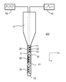
- FIG. 1 schematically shows a probe according to the present invention
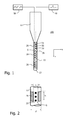
- FIG. 2 shows electrodes of the probe of FIG. 1 in more detail.
- Brain mapping (recording electrical brain activity and/or applying electrical brain stimulation) is a commonly used technique during neurosurgical procedures, for instance the implantation of DBS (Deep Brain Stimulation) electrodes.
- DBS Deep Brain Stimulation
- Known brain-mapping probes consist of needle-like devices with a single micro-electrode at the tip suited for recording the brain activity and a macro-electrode on the needle shaft for delivery of stimulation. Recording is performed by positioning the micro-electrode tip in the target. For stimulation the tip is retracted in the needle shaft and the larger macro-electrode at the distal end of the needle shaft is advanced towards the target. This is a cumbersome procedure and consumes a lot of time since the needle needs to be advanced multiple times for a complete spatial mapping of the target area and further it is not possible to easily record and stimulate from the same region.
- a probe design for acute brain mapping comprises a multitude of microelectrode sites for recording purposes distributed along the probe shaft (e.g. on a line), and one or more stimulation electrodes “wrapped” around the probe shaft and having an aperture or gap in the wrapped electrode at the position of the line of micro-electrodes.
- FIGS. 1 and 2 show a probe 100 that is designed according to the aforementioned general principles.
- the probe 100 comprises a body made of an electrically isolating material (e.g. some polymer), said body consisting of a trunk 12 and a shaft 11 which extends axially in z-direction for insertion into the brain.
- a typical value for the diameter d of the shaft 11 is about 300 ⁇ m.
- a plurality of stimulation electrodes 20 is arranged along the axial extension of the shaft 11 .
- Each stimulation electrode 20 has the form of an open cylinder or ring that wraps around the shaft 11 , leaving only a gap G of width x open.
- the gap width x typically has a value of about 40 ⁇ m.
- the axial height h of the stimulation electrode 20 may typically have a value of about 1 mm, providing an electrode area of about 0.9 mm 2 .
- the gaps could optionally also be tilted with respect to the z-axis and/or could have varying width x at different axial positions along their extension.
- a plurality of recording electrodes 31 , 32 , 33 is disposed within the gaps G of the stimulation electrodes 20 .
- the recording electrodes 31 - 33 in one gap G are aligned in axial direction, while the gaps of different stimulation electrodes 20 are rotated about the axis of the shaft 11 with respect to each other.
- the stimulation electrodes 20 and the recording electrodes 31 - 33 are electrically connected to wires (only partially shown) that provide external electrical access to these electrodes.
- the stimulation electrodes 20 are connected to a stimulation module 50 that can deliver electrical pulses to them, while the recording electrodes 31 , 32 , 33 , 35 are connected to a recording module 40 that records and processes their signals.
- the design of the probe 100 has the advantage that stimulation and recording of neural activity can be done at about the same position, particularly at exactly the same axial position (z-direction) with respect to the shaft 11 . If the different circumferential positions of the stimulation electrodes 20 and the recording electrodes 31 - 33 should matter, the whole probe 100 can readily be rotated about the axis of the shaft 11 in order to match the positions of the recording electrodes with the (previous) position of the associated stimulation electrode and vice versa. Such a rotation can much easier and more precisely be done than an axial displacement of the whole probe 100 which would be needed to sequentially match axially different positions of recording and stimulation electrodes.
- the tip 13 of the shaft 11 is preferably rounded in order to minimize or avoid injury during insertion of the shaft into the brain.
- the shaft 11 be provided with further electrodes, for example additional recording electrodes 35 that are not located within a gap of a stimulation electrode. These additional electrodes 35 are preferably located on a common line with the recording electrodes in the gaps G.
- the invention relates to a probe 100 for (particularly acute) stimulation and recording neural activity in the brain, said probe comprising an axially extending shaft 11 .
- At least one stimulation electrode 20 partially encircles the shaft besides at a gap G, wherein one or more recording electrodes 31 , 32 , 33 are located in said gap G.
- Recording and stimulation can be done simultaneously.
- the wrapped stimulation electrode allows delivering stimulation current in 3D fashion similar to a regular macro ring-electrode.
- the micro-array of recording electrodes allows recording of brain signals similar to normal micro-electrodes.
- the interruption of the stimulation electrode by a gap prevents electrical shunting of the recording electrodes (as would be the case for embedded recording electrodes).
Abstract
Description
- This application claims the benefit of European Patent Application No. 11150938.6 filed on Jan. 14, 2011, which is incorporated herein by reference in its entirety.
- The present invention generally relates to a probe for stimulation and recording of neural activity of the brain.
- From U.S. Patent Application Publication No. 2007/0123765, a device for brain stimulation is known with a longitudinally extending surface on which a plurality of cylindrical stimulation electrodes is disposed. Axially between two such stimulation electrodes, a plurality of smaller recording electrodes is arranged.
- Based on this background it was an object of the present invention to provide means for the stimulation and recording of neural activity in the brain, wherein it is desirable that physiologically relevant signals can readily be recorded.
- This object is achieved by a probe according to claim 1 and a system according to claim 14. Preferred embodiments are disclosed in the dependent claims.
- The probe according to the present invention serves for the stimulation and recording of neural activity in the brain, particularly for acute stimulation and recording (i.e. for a short-term use). In some embodiments, the probe comprises the following components:
- a) A shaft that extends longitudinally in some “axial” direction. The shaft will typically have a rod-like or filamentary shape and a sufficient stability such that it can be advanced through neural tissue.
b) At least one electrode which will be called “stimulation electrode” in the following because it is intended for delivering electrical stimulation pulses to surrounding neural tissue. The stimulation electrode shall partially encircle the shaft in the form of a ring which is open at (at least one) axially extending gap. Here and in the following, the term “axially” shall refer to the axis of the shaft.
c) At least one electrode which will be called “recording electrode” in the following because it is intended for sensing/recording electrical signals generated in surrounding neural tissue. The at least one recording electrode is disposed in the aforementioned gap of the stimulation electrode (electrically isolated from the latter). - A probe with the above design has the advantage that stimulation as well as recording can be done at substantially the same position without a need to move the probe between a stimulation and a recording event. The arrangement of the stimulation and recording electrodes at the same axial position of the shaft is particularly advantageous in this context (and preferred over an axially displaced arrangement at the same circumferential position of the shaft) because the more elongated axial direction of the probe has a higher probability to be crossing through multiple functional regions. Hence it is important to ensure that recording and stimulation can be performed at substantially equivalent positions, i.e. along the axis of the shaft. Moreover, the area of the stimulation electrode can be enlarged to any practically desired value by increasing its axial extension, wherein such an enlargement has no drawbacks with respect to the spatial matching of stimulation and recording because recording electrodes can readily cover any axial extension of the stimulation electrode.
- The gap of the stimulation electrode may extend straightly and parallel to the axial direction. It may however also be locally slanted with respect to the axial direction. The gap may for example “spiral” along the shaft or have a “wavy” shape. Such shapes may have the advantage of generating more homogeneous stimulation fields in axial direction.
- Moreover, the gap may have equal or varying width along its extension.
- Optionally a plurality of recording electrodes may be disposed in a single gap of a stimulation electrode. Most preferably, a number of two to about ten recording electrodes is provided in the gap of the stimulation electrode.
- When a plurality of recording electrodes is disposed in a gap of a stimulation electrode, these recording electrodes are preferably aligned (i.e. disposed one next to the other) in the direction of the gap (e.g. in axial direction for an axially extending gap). In this way it is possible to keep the gap in the stimulation electrode as small as possible.
- According to another embodiment of the invention, the probe may comprise a plurality of stimulation electrodes of the kind described, i.e. stimulation electrodes that form an open ring around the shaft with at least one recording electrode being located in their gap. Preferably, a number of two to about eight such stimulation electrodes may be provided on the shaft of the probe. These stimulation electrodes may be distributed uniformly or in any other appropriate pattern along the axis of the probe.
- According to a particular embodiment of the aforementioned design, the gaps of the stimulation electrodes are aligned in axial direction.
- According to another preferred embodiment of the design with a plurality of stimulation electrodes, the gaps of at least two such stimulation electrodes are rotated with respect to each other (about the axis of the shaft). Most preferably, each gap is rotated with respect to the gaps of all other stimulation electrodes. In this case recording electrodes can be distributed all around the circumference of the probe.
- To keep the stimulation site as close as possible to a recording site, the gap in the stimulation electrode will usually be as small as possible. In a preferred embodiment, the gap extends over about 1° to about 45° of the circumference of the shaft, preferably over about 5° to about 30°.
- The diameter of the shaft (and hence the corresponding ring-diameter of the stimulation electrode) optionally ranges between about 200 micron and about 2 mm, preferably between about 200 micron and about 1.3 mm, most preferably between about 200 micron and about 600 micron.
- The area of a stimulation electrode must be large enough such that this electrode is capable to deliver a desired stimulation current, i.e. that the impedance between the electrode and surrounding neural tissue is not too high. Most preferably, the stimulation electrode has an area between about 0.3 mm2 and about 3 mm2.
- The axial extension of a single stimulation electrode preferably ranges between about 500 and about 2000 micron. With these values, the aforementioned preferred area size of the stimulation electrodes can be achieved for typical shaft diameters.
- As the recording electrode shall sense electrical signals of single neuron activity, its size can be (much) smaller than that of a stimulation electrode. Preferably, the recording electrode has an area between about 100 mm2 and about 10,000 mm2.
- The tip of the probe is preferably rounded to minimize or avoid injury during insertion of the probe into neural tissue.
- The invention further relates to a brain stimulation and recording system that comprises a probe of the kind described above, i.e. with an axially extended shaft, at least one stimulation electrode that partially encircles the shaft in the form of a ring which is open at a gap, and at least one recording electrode that is disposed in said gap of the stimulation electrode. Moreover, the system comprises a recording module for recording and processing signals from the recording electrodes, said recording module being coupled (by wire or wirelessly) to the recording electrodes, and a stimulation module coupled to the stimulation electrode for delivering electrical pulses (of any kind and shape) to it.
- These and other aspects of the invention will be apparent from and elucidated with reference to the embodiment(s) described hereinafter. These embodiments will be described by way of example with the help of the accompanying drawings in which:
-
FIG. 1 schematically shows a probe according to the present invention; and -
FIG. 2 shows electrodes of the probe ofFIG. 1 in more detail. - Like reference numbers in the Figures refer to identical or similar components.
- Brain mapping (recording electrical brain activity and/or applying electrical brain stimulation) is a commonly used technique during neurosurgical procedures, for instance the implantation of DBS (Deep Brain Stimulation) electrodes. Known brain-mapping probes consist of needle-like devices with a single micro-electrode at the tip suited for recording the brain activity and a macro-electrode on the needle shaft for delivery of stimulation. Recording is performed by positioning the micro-electrode tip in the target. For stimulation the tip is retracted in the needle shaft and the larger macro-electrode at the distal end of the needle shaft is advanced towards the target. This is a cumbersome procedure and consumes a lot of time since the needle needs to be advanced multiple times for a complete spatial mapping of the target area and further it is not possible to easily record and stimulate from the same region.
- A probe design for acute brain mapping is therefore proposed that comprises a multitude of microelectrode sites for recording purposes distributed along the probe shaft (e.g. on a line), and one or more stimulation electrodes “wrapped” around the probe shaft and having an aperture or gap in the wrapped electrode at the position of the line of micro-electrodes.
-
FIGS. 1 and 2 show aprobe 100 that is designed according to the aforementioned general principles. Theprobe 100 comprises a body made of an electrically isolating material (e.g. some polymer), said body consisting of atrunk 12 and ashaft 11 which extends axially in z-direction for insertion into the brain. A typical value for the diameter d of theshaft 11 is about 300 μm. - A plurality of
stimulation electrodes 20 is arranged along the axial extension of theshaft 11. Eachstimulation electrode 20 has the form of an open cylinder or ring that wraps around theshaft 11, leaving only a gap G of width x open. For the above value of the shaft diameter d, the gap width x typically has a value of about 40 μm. The axial height h of thestimulation electrode 20 may typically have a value of about 1 mm, providing an electrode area of about 0.9 mm2. The gaps could optionally also be tilted with respect to the z-axis and/or could have varying width x at different axial positions along their extension. - Within the gaps G of the
stimulation electrodes 20, a plurality ofrecording electrodes FIG. 1 , the recording electrodes 31-33 in one gap G are aligned in axial direction, while the gaps ofdifferent stimulation electrodes 20 are rotated about the axis of theshaft 11 with respect to each other. - Within the
shaft 11 and thetrunk 12, thestimulation electrodes 20 and the recording electrodes 31-33 are electrically connected to wires (only partially shown) that provide external electrical access to these electrodes. In particular, thestimulation electrodes 20 are connected to astimulation module 50 that can deliver electrical pulses to them, while therecording electrodes recording module 40 that records and processes their signals. - The design of the
probe 100 has the advantage that stimulation and recording of neural activity can be done at about the same position, particularly at exactly the same axial position (z-direction) with respect to theshaft 11. If the different circumferential positions of thestimulation electrodes 20 and the recording electrodes 31-33 should matter, thewhole probe 100 can readily be rotated about the axis of theshaft 11 in order to match the positions of the recording electrodes with the (previous) position of the associated stimulation electrode and vice versa. Such a rotation can much easier and more precisely be done than an axial displacement of thewhole probe 100 which would be needed to sequentially match axially different positions of recording and stimulation electrodes. - The
tip 13 of theshaft 11 is preferably rounded in order to minimize or avoid injury during insertion of the shaft into the brain. Moreover, it should be noted that theshaft 11 be provided with further electrodes, for exampleadditional recording electrodes 35 that are not located within a gap of a stimulation electrode. Theseadditional electrodes 35 are preferably located on a common line with the recording electrodes in the gaps G. - In summary, the invention relates to a
probe 100 for (particularly acute) stimulation and recording neural activity in the brain, said probe comprising anaxially extending shaft 11. At least onestimulation electrode 20 partially encircles the shaft besides at a gap G, wherein one ormore recording electrodes - The main advantages of the proposed design are:
- Recording and stimulation of the same tissue region is possible without probe movement.
- Recording and stimulation can be done simultaneously.
- The wrapped stimulation electrode allows delivering stimulation current in 3D fashion similar to a regular macro ring-electrode.
- The micro-array of recording electrodes allows recording of brain signals similar to normal micro-electrodes.
- The interruption of the stimulation electrode by a gap prevents electrical shunting of the recording electrodes (as would be the case for embedded recording electrodes).
- It is to be understood that at least some of the figures and descriptions of the invention have been simplified to focus on elements that are relevant for a clear understanding of the invention, while eliminating, for purposes of clarity, other elements that those of ordinary skill in the art will appreciate may also comprise a portion of the invention. However, because such elements are well known in the art, and because they do not necessarily facilitate a better understanding of the invention, a description of such elements is not provided herein.
- Finally it is pointed out that in the present application the term “comprising” does not exclude other elements or steps, that “a” or “an” does not exclude a plurality, and that a single processor or other unit may fulfill the functions of several means. The invention resides in each and every novel characteristic feature and each and every combination of characteristic features. Moreover, reference signs in the claims shall not be construed as limiting their scope.
Claims (14)
Applications Claiming Priority (2)
| Application Number | Priority Date | Filing Date | Title |
|---|---|---|---|
| EP11150938 | 2011-01-14 | ||
| EP11150938.6 | 2011-01-14 |
Publications (1)
| Publication Number | Publication Date |
|---|---|
| US20120184837A1 true US20120184837A1 (en) | 2012-07-19 |
Family
ID=45478333
Family Applications (1)
| Application Number | Title | Priority Date | Filing Date |
|---|---|---|---|
| US13/349,895 Abandoned US20120184837A1 (en) | 2011-01-14 | 2012-01-13 | Brain Mapping Probe |
Country Status (4)
| Country | Link |
|---|---|
| US (1) | US20120184837A1 (en) |
| EP (1) | EP2663361A1 (en) |
| DE (1) | DE202012012950U1 (en) |
| WO (1) | WO2012095529A1 (en) |
Cited By (15)
| Publication number | Priority date | Publication date | Assignee | Title |
|---|---|---|---|---|
| US8774937B2 (en) | 2009-12-01 | 2014-07-08 | Ecole Polytechnique Federale De Lausanne | Microfabricated surface neurostimulation device and methods of making and using the same |
| US8788042B2 (en) | 2008-07-30 | 2014-07-22 | Ecole Polytechnique Federale De Lausanne (Epfl) | Apparatus and method for optimized stimulation of a neurological target |
| US8788064B2 (en) | 2008-11-12 | 2014-07-22 | Ecole Polytechnique Federale De Lausanne | Microfabricated neurostimulation device |
| US9364659B1 (en) * | 2015-04-27 | 2016-06-14 | Dantam K. Rao | Smart lead for deep brain stimulation |
| US9403011B2 (en) | 2014-08-27 | 2016-08-02 | Aleva Neurotherapeutics | Leadless neurostimulator |
| US9474894B2 (en) | 2014-08-27 | 2016-10-25 | Aleva Neurotherapeutics | Deep brain stimulation lead |
| US9549708B2 (en) | 2010-04-01 | 2017-01-24 | Ecole Polytechnique Federale De Lausanne | Device for interacting with neurological tissue and methods of making and using the same |
| US9925376B2 (en) | 2014-08-27 | 2018-03-27 | Aleva Neurotherapeutics | Treatment of autoimmune diseases with deep brain stimulation |
| US10932862B2 (en) | 2015-05-10 | 2021-03-02 | Alpha Omega Neuro Technologies Ltd. | Automatic brain probe guidance system |
| US10966620B2 (en) | 2014-05-16 | 2021-04-06 | Aleva Neurotherapeutics Sa | Device for interacting with neurological tissue and methods of making and using the same |
| US11051889B2 (en) | 2015-05-10 | 2021-07-06 | Alpha Omega Engineering Ltd. | Brain navigation methods and device |
| US11234632B2 (en) * | 2015-05-10 | 2022-02-01 | Alpha Omega Engineering Ltd. | Brain navigation lead |
| US11266830B2 (en) | 2018-03-02 | 2022-03-08 | Aleva Neurotherapeutics | Neurostimulation device |
| US11311718B2 (en) | 2014-05-16 | 2022-04-26 | Aleva Neurotherapeutics Sa | Device for interacting with neurological tissue and methods of making and using the same |
| US11589790B2 (en) | 2016-05-20 | 2023-02-28 | Imperial College Innovations Limited | Implantable neural interface |
Citations (6)
| Publication number | Priority date | Publication date | Assignee | Title |
|---|---|---|---|---|
| US5843148A (en) * | 1996-09-27 | 1998-12-01 | Medtronic, Inc. | High resolution brain stimulation lead and method of use |
| US7809446B2 (en) * | 2005-01-05 | 2010-10-05 | Boston Scientific Neuromodulation Corporation | Devices and methods for brain stimulation |
| US20100268298A1 (en) * | 2009-04-16 | 2010-10-21 | Boston Scientific Neuromodulation Corporation | Deep brain stimulation current steering with split electrodes |
| US7941202B2 (en) * | 2005-10-07 | 2011-05-10 | Neuronexus Technologies | Modular multichannel microelectrode array and methods of making same |
| US20120071949A1 (en) * | 2010-09-21 | 2012-03-22 | Boston Scientific Neuromodulation Corporation | Systems and methods for making and using radially-aligned segmented electrodes for leads of electrical stimulation systems |
| US8224417B2 (en) * | 2007-10-17 | 2012-07-17 | Neuronexus Technologies, Inc. | Guide tube for an implantable device system |
-
2012
- 2012-01-13 US US13/349,895 patent/US20120184837A1/en not_active Abandoned
- 2012-01-13 DE DE202012012950.3U patent/DE202012012950U1/en not_active Expired - Lifetime
- 2012-01-13 EP EP12700285.5A patent/EP2663361A1/en not_active Withdrawn
- 2012-01-13 WO PCT/EP2012/050522 patent/WO2012095529A1/en active Application Filing
Patent Citations (6)
| Publication number | Priority date | Publication date | Assignee | Title |
|---|---|---|---|---|
| US5843148A (en) * | 1996-09-27 | 1998-12-01 | Medtronic, Inc. | High resolution brain stimulation lead and method of use |
| US7809446B2 (en) * | 2005-01-05 | 2010-10-05 | Boston Scientific Neuromodulation Corporation | Devices and methods for brain stimulation |
| US7941202B2 (en) * | 2005-10-07 | 2011-05-10 | Neuronexus Technologies | Modular multichannel microelectrode array and methods of making same |
| US8224417B2 (en) * | 2007-10-17 | 2012-07-17 | Neuronexus Technologies, Inc. | Guide tube for an implantable device system |
| US20100268298A1 (en) * | 2009-04-16 | 2010-10-21 | Boston Scientific Neuromodulation Corporation | Deep brain stimulation current steering with split electrodes |
| US20120071949A1 (en) * | 2010-09-21 | 2012-03-22 | Boston Scientific Neuromodulation Corporation | Systems and methods for making and using radially-aligned segmented electrodes for leads of electrical stimulation systems |
Cited By (32)
| Publication number | Priority date | Publication date | Assignee | Title |
|---|---|---|---|---|
| US8788042B2 (en) | 2008-07-30 | 2014-07-22 | Ecole Polytechnique Federale De Lausanne (Epfl) | Apparatus and method for optimized stimulation of a neurological target |
| US9072906B2 (en) | 2008-07-30 | 2015-07-07 | Ecole Polytechnique Federale De Lausanne | Apparatus and method for optimized stimulation of a neurological target |
| US10166392B2 (en) | 2008-07-30 | 2019-01-01 | Ecole Polytechnique Federale De Lausanne | Apparatus and method for optimized stimulation of a neurological target |
| US10952627B2 (en) | 2008-07-30 | 2021-03-23 | Ecole Polytechnique Federale De Lausanne | Apparatus and method for optimized stimulation of a neurological target |
| US8788064B2 (en) | 2008-11-12 | 2014-07-22 | Ecole Polytechnique Federale De Lausanne | Microfabricated neurostimulation device |
| US10406350B2 (en) | 2008-11-12 | 2019-09-10 | Ecole Polytechnique Federale De Lausanne | Microfabricated neurostimulation device |
| US9440082B2 (en) | 2008-11-12 | 2016-09-13 | Ecole Polytechnique Federale De Lausanne | Microfabricated neurostimulation device |
| US11123548B2 (en) | 2008-11-12 | 2021-09-21 | Ecole Polytechnique Federale De Lausanne | Microfabricated neurostimulation device |
| US9604055B2 (en) | 2009-12-01 | 2017-03-28 | Ecole Polytechnique Federale De Lausanne | Microfabricated surface neurostimulation device and methods of making and using the same |
| US9192767B2 (en) | 2009-12-01 | 2015-11-24 | Ecole Polytechnique Federale De Lausanne | Microfabricated surface neurostimulation device and methods of making and using the same |
| US8774937B2 (en) | 2009-12-01 | 2014-07-08 | Ecole Polytechnique Federale De Lausanne | Microfabricated surface neurostimulation device and methods of making and using the same |
| US9549708B2 (en) | 2010-04-01 | 2017-01-24 | Ecole Polytechnique Federale De Lausanne | Device for interacting with neurological tissue and methods of making and using the same |
| US11766560B2 (en) | 2010-04-01 | 2023-09-26 | Ecole Polytechnique Federale De Lausanne | Device for interacting with neurological tissue and methods of making and using the same |
| US10966620B2 (en) | 2014-05-16 | 2021-04-06 | Aleva Neurotherapeutics Sa | Device for interacting with neurological tissue and methods of making and using the same |
| US11311718B2 (en) | 2014-05-16 | 2022-04-26 | Aleva Neurotherapeutics Sa | Device for interacting with neurological tissue and methods of making and using the same |
| US10201707B2 (en) | 2014-08-27 | 2019-02-12 | Aleva Neurotherapeutics | Treatment of autoimmune diseases with deep brain stimulation |
| US11167126B2 (en) | 2014-08-27 | 2021-11-09 | Aleva Neurotherapeutics | Deep brain stimulation lead |
| US9925376B2 (en) | 2014-08-27 | 2018-03-27 | Aleva Neurotherapeutics | Treatment of autoimmune diseases with deep brain stimulation |
| US10441779B2 (en) | 2014-08-27 | 2019-10-15 | Aleva Neurotherapeutics | Deep brain stimulation lead |
| US11730953B2 (en) | 2014-08-27 | 2023-08-22 | Aleva Neurotherapeutics | Deep brain stimulation lead |
| US9889304B2 (en) | 2014-08-27 | 2018-02-13 | Aleva Neurotherapeutics | Leadless neurostimulator |
| US9572985B2 (en) | 2014-08-27 | 2017-02-21 | Aleva Neurotherapeutics | Method of manufacturing a thin film leadless neurostimulator |
| US9403011B2 (en) | 2014-08-27 | 2016-08-02 | Aleva Neurotherapeutics | Leadless neurostimulator |
| US9474894B2 (en) | 2014-08-27 | 2016-10-25 | Aleva Neurotherapeutics | Deep brain stimulation lead |
| US10065031B2 (en) | 2014-08-27 | 2018-09-04 | Aleva Neurotherapeutics | Deep brain stimulation lead |
| US9364659B1 (en) * | 2015-04-27 | 2016-06-14 | Dantam K. Rao | Smart lead for deep brain stimulation |
| US11234632B2 (en) * | 2015-05-10 | 2022-02-01 | Alpha Omega Engineering Ltd. | Brain navigation lead |
| US11051889B2 (en) | 2015-05-10 | 2021-07-06 | Alpha Omega Engineering Ltd. | Brain navigation methods and device |
| US10932862B2 (en) | 2015-05-10 | 2021-03-02 | Alpha Omega Neuro Technologies Ltd. | Automatic brain probe guidance system |
| US11589790B2 (en) | 2016-05-20 | 2023-02-28 | Imperial College Innovations Limited | Implantable neural interface |
| US11266830B2 (en) | 2018-03-02 | 2022-03-08 | Aleva Neurotherapeutics | Neurostimulation device |
| US11738192B2 (en) | 2018-03-02 | 2023-08-29 | Aleva Neurotherapeutics | Neurostimulation device |
Also Published As
| Publication number | Publication date |
|---|---|
| DE202012012950U1 (en) | 2014-05-12 |
| EP2663361A1 (en) | 2013-11-20 |
| WO2012095529A1 (en) | 2012-07-19 |
Similar Documents
| Publication | Publication Date | Title |
|---|---|---|
| US20120184837A1 (en) | Brain Mapping Probe | |
| JP6158440B2 (en) | Method for manufacturing molded segment electrode leads | |
| JP6072986B2 (en) | Lead having segment electrode and method of manufacturing and using lead | |
| US6597953B2 (en) | Furcated sensing and stimulation lead | |
| US8897891B2 (en) | Leads with electrode carrier for segmented electrodes and methods of making and using | |
| JP5908611B2 (en) | System and method for identifying circumferential positioning of lead electrodes for electrical stimulation systems | |
| US8755905B2 (en) | Devices and methods for brain stimulation | |
| JP5889917B2 (en) | Method of manufacturing a lead having segmented electrodes for an electrical stimulation system | |
| JP5165575B2 (en) | Electrode bundle | |
| US8442654B2 (en) | Electrode array with electrodes having cutout portions and methods of making the same | |
| US20150038979A1 (en) | Leads with segmented electrodes for electrical stimulation of planar regions and methods of making and using | |
| JP2016519987A (en) | Method for manufacturing split electrode leads using removable rings and leads formed thereby | |
| JP2016519988A (en) | Leads containing split electrodes with non-vertical legs and methods of making and using | |
| US20100100152A1 (en) | Electrode system for deep brain stimulation | |
| JP2016527054A (en) | System and method for manufacturing and using segmented tip electrodes for electrical stimulation system leads | |
| JP2013537836A (en) | System and method for manufacturing and using radially aligned segment electrodes for electrical stimulation system leads | |
| EP2810689A1 (en) | A system for planning and/or providing a therapy for neural applications | |
| JP2020534045A (en) | Imaging markers for stimulator reeds | |
| US20160144166A1 (en) | Medical lead with thin film | |
| JP2015520006A (en) | Provisional implantable medical electrical stimulation lead | |
| US20130150931A1 (en) | Distributed neural stimulation array system | |
| US10524681B2 (en) | Lead and a system for medical applications | |
| US20230363709A1 (en) | Electrode orientation detection | |
| Slopsema et al. | Advancing directional deep brain stimulation array technology | |
| NL2012518B1 (en) | Medical lead and system for neurostimulation. |
Legal Events
| Date | Code | Title | Description |
|---|---|---|---|
| AS | Assignment |
Owner name: KONINKLIJKE PHILIPS ELECTRONICS N.V., NETHERLANDS Free format text: ASSIGNMENT OF ASSIGNORS INTEREST;ASSIGNORS:MARTENS, HUBERT CECILE FRANCOIS;WANG, KE;REEL/FRAME:030100/0808 Effective date: 20110530 |
|
| AS | Assignment |
Owner name: SAPIENS STEERING BRAIN STIMULATION B.V., NETHERLAN Free format text: ASSIGNMENT OF ASSIGNORS INTEREST;ASSIGNOR:KONINKLIJKE PHILIPS ELECTRONICS N.V.;REEL/FRAME:030100/0884 Effective date: 20130204 |
|
| STCB | Information on status: application discontinuation |
Free format text: ABANDONED -- FAILURE TO RESPOND TO AN OFFICE ACTION |