US2488638A - Writing instrument - Google Patents
Writing instrument Download PDFInfo
- Publication number
- US2488638A US2488638A US680129A US68012946A US2488638A US 2488638 A US2488638 A US 2488638A US 680129 A US680129 A US 680129A US 68012946 A US68012946 A US 68012946A US 2488638 A US2488638 A US 2488638A
- Authority
- US
- United States
- Prior art keywords
- barrel
- piston
- plunger rod
- gasket
- rod
- Prior art date
- Legal status (The legal status is an assumption and is not a legal conclusion. Google has not performed a legal analysis and makes no representation as to the accuracy of the status listed.)
- Expired - Lifetime
Links
- 239000000463 material Substances 0.000 description 27
- 238000007789 sealing Methods 0.000 description 6
- 210000002445 nipple Anatomy 0.000 description 5
- 230000002093 peripheral effect Effects 0.000 description 3
- 241000606643 Anaplasma centrale Species 0.000 description 2
- 230000006835 compression Effects 0.000 description 2
- 238000007906 compression Methods 0.000 description 2
- 235000011837 pasties Nutrition 0.000 description 2
- 230000000153 supplemental effect Effects 0.000 description 2
- HSRJKNPTNIJEKV-UHFFFAOYSA-N Guaifenesin Chemical compound COC1=CC=CC=C1OCC(O)CO HSRJKNPTNIJEKV-UHFFFAOYSA-N 0.000 description 1
- 230000037431 insertion Effects 0.000 description 1
- 238000003780 insertion Methods 0.000 description 1
- 239000010985 leather Substances 0.000 description 1
- 239000004033 plastic Substances 0.000 description 1
- 239000004636 vulcanized rubber Substances 0.000 description 1
Images
Classifications
-
- B—PERFORMING OPERATIONS; TRANSPORTING
- B43—WRITING OR DRAWING IMPLEMENTS; BUREAU ACCESSORIES
- B43K—IMPLEMENTS FOR WRITING OR DRAWING
- B43K7/00—Ball-point pens
- B43K7/02—Ink reservoirs; Ink cartridges
- B43K7/03—Ink reservoirs; Ink cartridges pressurised, e.g. by gas
-
- B—PERFORMING OPERATIONS; TRANSPORTING
- B43—WRITING OR DRAWING IMPLEMENTS; BUREAU ACCESSORIES
- B43K—IMPLEMENTS FOR WRITING OR DRAWING
- B43K5/00—Pens with ink reservoirs in holders, e.g. fountain-pens
- B43K5/18—Arrangements for feeding the ink to the nibs
- B43K5/1818—Mechanical feeding means, e.g. valves; Pumps
- B43K5/189—Pumps
Definitions
- theepen as theswritingi material adjacent .
- the r-writingball Another: object is the: provision of: improved mean'ssforpreventing-leakage of the writing,- material' through-the. assembled "partsvat izheerear end of theepen barrel-r.
- a further object is to provide improvedmeans for. advancing,-the massmf: writing materialzin thezpenz barrel. by pushing; a button. at. the rear end of l thfi'fllfifl: barrel. each time 1 itis" desired; to urge the writing; material forward i inthe. barrel.
- Anotherl obj ect. is Tto-providesimple. and positive meansfo-r selectively'advancing the writing material. .pleasinglin app aranceandihavingi appeal to penlusersl
- A- furthen obj act is the provision of: improved meanslfor moving; thelwriting material-.forward in.the pen barrel :adapted to movethe. entire: mass of lwritingfmaterial forward and wiping; the walls ofthe. bore of. the barrelswhereby. none: of the writing material' is left. adhering tolsaid walls rearwardlyrof the mass of-writingmaterial; .thereby increasing-the. time-between pen fil1ings.--
- Another. object is the: provisiom ofs improved gasketImea-ns adapted to" prevent leakage there-- through: as. it. is. moved. forwardlw in the pen barrel;v
- a further. object is toprovide a piston adapted to be moved a predetermined-distance.-toward.the gasket andl writingmaterial with. provision .inr. termedietethe-piston.and .the forward portion of the" gasketlof' resilient-means exerting. aresilient pressurelagainsttherear endl'of. themassotwrih. ing material.
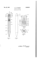
- Figure. 1 is an axialsection-tliroughia-penl-ems bodyingthe invention
- Fig. Z is an elevationall view ofltlie: pen. of. Fi'g. 1.
- Fig. 3J is an enlarged fragmentary axiahsection' taken alongi'line 3.3"ofFig, 11.
- Fig; 4' is a sectional' view taken alongrli'ne t's-4'. ofFig; 3'.
- thelpreferred form of mysine vention comprises a :mainbod-y portionor barrel lfl aztip member l2 removably'secured-to the forwardsend of thebarrel I0,- anipplemember. I4 removably secured. to the rear endof the barrel a cap.- member- I 6 removably secured: to the erea-rz end ofthe? nipple memben-a-spring- [8- intermediate the assembled. nipple. member and cap-member, a-. piston. 211 and an. associated gas- Ket ZZ- adapted for. longitudinal movement within "the: bore. of the barrel and.
- aplungerrod 24 adapted-atosdectively move the associated pisrtom-and. gasket forwardly in. the bore ofthe bar-rel;-,.the spring. l8.being adaptedto normally, urge the plunger rod in a directiontoward the rear. endiof the barrel..
- the space 2-6- forwardly Ofrthfi gasket-22 may be'filledwith a pasty-writingmat-eriahl Eigtllillustratingthe relative positionloiithe severalpants of the-pen when-it is filled. with writingtmaterial.
- Thenipple member I 4 may comprise a sleeve provide d.withl a. central bore 2 8 adj acent its rearend portion, altransverserwall 30 defining the forward endpfithebore- 2 8.
- the opposed ends of the.-:nipple..member. may, bev externally threaded, theopposedthreaded .endsbeing separatedby an outwardlyprojectingiateral ring-portionfillarger in diameter than the said threaded ends, adapted toser.ve:asa---shoulder member to-abut-the rear endioflthe-barrel and the forward endofthe cap member. of. .theassembled. pen.
- the bore 28 of the nipplemember. Ill and. the bore of. the assembled cap. member. [6' may be of uniform diameter. adaptedit'o. form a. cavityv forhousing the spring- IBL.
- Thepistbnilll may comprise .a. cylindrical membent! Isli'gl'itly. smaller in diameter than thediamr etenof the boresofthe-barrel.v liltadapted for slidiing movement. in thebore .of the. barrel.
- the pistons may. haveea central; aperture. 38. there.-
- the opposed resilient members-All maybenormallyurged. atetheir free .ends toward each-. others into enga ement. with v the. opposed sidsoflthe-phnger rod. 2.4.
- the se: curedaends.- ofthe.1-members- 4D maybe formed with: angularfportions: 4-1" adapted. to interlockthe i members; 481 with .the piston? member; the portionsiM-i beingiparticularly adaptable: for: this 3 purpose where the piston is moulded of plastic material.
- the gasket 22 may be made of a yieldable material such as rubber, felt, leather and the like and may comprise a cup-shaped member having a wall 42 disposed transversely of the bore of the barrel l and in flatwise abutting relation with the forward surface of the piston 20.
- the peripheral portion of the wall 42 may be formed with a depending forwardly extending wall 44 adapted to closely register with the bore in the barrel.
- the inner surface of the wall .44 may taper inwardly and rearwardly from a relatively thin edge to the wall 42.
- the wall 42 may be formed with a sleeve 46 extending forwardly therefrom and defining a central aperture 48 coaxial with the bore of the barrel 10.
- the outer wall of the sleeve 46 may taper outwardly and rearwardly from a relatively thin edge to the wall 42.
- the aperture 48 may be of uniform diameter throughout its major forward length and may be formed with an enlarged portion 58 adjacent its rear end.
- the gasket may be secured to the adjacent surface of the piston 2
- the plunger rod 24 may comprise an elongated round rod formed at its rear end with an enlarged push-button member 52.
- a laterally disposed washer-like member 54 of larger diameter than the diameter of the member 52 may be formed on the rod adjacent the connection of the rod with the member 52.
- the forward and rear end portions of the rod may be plain for a predetermined length and the intermediate portion of the rod may be provided with a series of abutments 56 cut or otherwise formed therein.
- the forward end of each abutment 56 may be equal in diameter to the diameter of the rod and each abutment may taper rearwardly and inwardly from its forward end to the next adjacent abutment.
- the associated piston 20' and gasket 22 may be disposed within the barrel II] in the relative position indicated in Fig. 1 when the space 26 of the barrel is filled with writing material.
- the plunger rod 24 may be centrally and longitudinally disposed within the bore of the barrel In with the abutment portion of the rod extending through the aligned apertures 38 and 48 of the piston and gasket, respectively.
- the rear plain end portion of the plunger rod may extend through a central aperture 3
- the push-button member 52 may extend through the central aperture in the wall 34 of the cap member and may extend rearwardly of the wall 34 a predetermined distance substantially equal to the desired forward stroke of the plunger rod required to move the piston forward a notch at a time.
- the opposed free ends of the resilient members 4!] may be in abutting relation with the abutment nearest the rear end of the plunger rod whereby, upon the forward movement of the plunger rod, the piston 28 will be moved forward in the barrel II] a distance equal to the stroke of the plunger rod, this distance being substantially equal to the distance between adjacent abutments 5B of the plunger rod.
- the piston 20 and associated resilient members 40 Upon each forward stroke of the plunger rod, the piston 20 and associated resilient members 40 will be advanced in the barrel a distance equal to the length of an abutment 56 and the plunger rod will return to its normal position by means of the spring l8. During the return movement of the plunger rod, the opposed free ends of the resilient members 40 will move into interlocking engagement with the next forward abutment of the plunger rod, adapted to maintain the piston in its last advanced position and place the plunger rod in position where, upon the next forward stroke thereof, the piston will be advanced another notch.
- the members 40 require only enough spring to urge them at all times into engagement with the plunger rod and it will be seen from the drawing that the friction between the members 40 and the tapered side Walls of the abutments 56 will be so negligible that there will be no tendency for the spring-urged return of the plunger rod to pull the piston back with it. WhileI have shown the resilient members 40 as being substantially fiat in cross-section I contemplate the use of members 40 concavo-convex in cross-section in order to provide longitudinal rigidity of the members 40.
- the gasket 22 When the push-button member '52 is pushed inwardly the gasket 22 will be urged forwardly in the pen barrel, the wall 44 of the gasket being held in substantial sealing relation with the walls of the pen barrel by the compressed writing material. As the gasket moves forwardly in the pen barrel the last mentioned sealing relation will wipe the walls of the pen barrel, eliminate the possibility of any of the writing material adhering to the walls of the pen barrel rearwardly of the advancing gasket (eliminating leakage of the writing material at the cap member) and insure the use of the maximum amount of the supply of writing material; the latter increasing the length of periods between pen fillings.
- the sleeve 45 of the gasket 22, being resilient, will be pressed into sealing engagement with the contour of the abutment portion of the plunger rod by the action of the compressed writing material against the sleeve 46, thereby preventing leakage of the writing material from the forward reservoir 26 through the aligned apertures 38 and 48 of the piston and gasket, respectively.
- the rear end portion of the aperture 38 may be formed with an enlarged portion 60 similar to the enlarged portion 50 of the aperture 48; both enlarged portions being adapted to permit the abutments 56 of the plunger rod to enter the apertures 38 and 48 without interference.
- An aperture 58 may be formed in the forward end of the plunger rod for insertion therethrough of a pin or other suitable detent member adapted for the purpose of engaging the gasket for retraction thereof when the supply of writing material has been used up and the plunger rod is moved rearwardly to its initial rearward position.
- spring l8 may be replaced with other suitable resilient means, if desired.
- a spring [8 or equivalent having resistance to compression sufficient to prevent the accidental forward movement of the plunger rod and I further contemplate the use of a supplemental cap removably secured to the cap member l6 adapted to prevent pushing the plunger rod forward while the supplemental cap is in secured position.
- a combined piston and gasket such as a piston having the equivalent of resilient piston rings at its periphery although I prefer the structure shown in the drawings in order to provide some resiliency or give intermediate the writing material and the piston.
- the wall 42 of the gasket may be considerably thicker than shown in the drawings and may comprise a relatively soft, yieldable material whereby, when the plunger rod is pushed forward, the resiliency in the wall 42 may exert a light pressure against the mass of writing material not sufficient to force it out around the writing ball. Any suitable resilient means may be used intermediate the writing material and the piston. I propose to charge the pen barrel through the forward end thereof to avoid possible entrapment of air between the gasket and the writing material such as might occur if the barrel were charged from the rear end thereof.
- a gasket as shown in the drawings, having rearwardly tapering flexible walls 44 and a rearwardly tapering flexible sleeve 46.
- the wall 44 When the gasket is urged forwardly in the pen barrel, by the piston, the wall 44 will be urged into sealing engagement with the inner bore of the pen barrel due to a slight pressure in the mass of writing material against the wall 44.
- the resilient sleeve 46 may be similarly pressed into sealing engagement with the contour of the abutment portion of the plunger rod by this same pressure, this sealing engagement being relieved as the pressure in the mass of writing material is reduced, as it will be when the next forward movement of the plunger rod is indicated as being desirable.
- a fountain pen including a hollow barrel, a piston slidable in the barrel formed with an axial aperture, an elongated plunger rod extending slidably through said aperture, said rod formed with a series of rearwardly tapered ratchet teeth, an elongated leaf spring affixed to and having its major portion disposed lengthwise of the barrel rearwardly of the piston, the rear end of said spring being adapted through tension therein to normally wipingly engage said teeth when the plunger rod is moved in one direction and adapted to engage said teeth interlockingly when the plunger rod is moved in the opposite direction whereby said plunger rod may be moved axially in said one directlon without moving the piston and may be moved in said opposite direction to bodily move said piston, respectively.
- a resilient gasket formed with an axial aperture is disposed lorwaraly of the piston, said gasket having a forwardly extending peripheral iiallge adapted to closely register with and wipingly engage the interior wall of the barrel, the inner wall of said flange tapering rearwardly and inwardly from a thin forward circular edge.
- a resilient gasket is disposed forwardly of the piston formed with a forwardly extending central extension having an axial aperture therethrough in coaxial alignment with the plunger rod, the inner Wall of said aperture being parallel with said rod and the outer wall thereof bein tapered rearwardly and outwardly from a thin lorward circular edge, said edge being adapted to wipingly engage the periphery of said rod when the latter is moved axially through said gasket.
- a fountain pen including a hollow barrel, a piston formed with an axial aperture slidable in the barrel, an elongated plunger rod extending slidably through said aperture, said rod formed with a series of peripheral rearwardly tapered ratchet teeth, a pair of leaf springs secured to and having their major portions disposed lengthwise of the barrel on opposed sides of the plunger rod rearwardly of the piston, the rear ends of said springs being adapted through tension therein to wipingly engage said teeth when said rod is moved axially in one direction and adapted to interlockingly engage said teeth When the rod is moved in the opposite direction.
Description
Nov. 22, 1949 OCONNQR 2,488,638
I WRITING INSTRUMENT Filed June 28, 1946 4 Fig.2
IN V EN TOR.
Patented Nov. 22, 1949 U so ore-ice $488,638 WRITING INSTRUMENT A'rth'ur F'.'.0Connor,'.Cliicago; Ill:
Applicatiomlune28, 1946;;Serial N01.680129r ;Claims; (Cl. 120'-42T4)I The. invention relates to) fountain =pensxof--the typeiusing-alwritingmaterial h'avingsawpasty; consistenoy and: more particularly to. pens of this type employingsa rotatable writingi'rballatrthe forward tip: ofrth-espena An" object; of. the: invention: is to provide new and novel means for-selectively urging; the pasty writingamateria'l forward in :thebarrel of. theepen as theswritingi material adjacent .the r-writingball Another: object is": the: provision of: improved mean'ssforpreventing-leakage of the writing,- material' through-the. assembled "partsvat izheerear end of theepen barrel-r.
A further object is to provide improvedmeans for. advancing,-the massmf: writing materialzin thezpenz barrel. by pushing; a button. at. the rear end of l thfi'fllfifl: barrel. each time 1 itis" desired; to urge the writing; material forward i inthe. barrel.
Anotherl obj ect. is Tto-providesimple. and positive meansfo-r selectively'advancing the writing material. .pleasinglin app aranceandihavingi appeal to penlusersl A- furthen obj act is the provision of: improved meanslfor moving; thelwriting material-.forward in.the pen barrel :adapted to movethe. entire: mass of lwritingfmaterial forward and wiping; the walls ofthe. bore of. the barrelswhereby. none: of the writing material' is left. adhering tolsaid walls rearwardlyrof the mass of-writingmaterial; .thereby increasing-the. time-between pen fil1ings.-- Another. object is the: provisiom ofs improved gasketImea-ns adapted to" prevent leakage there-- through: as. it. is. moved. forwardlw in the pen barrel;v
A further. object is toprovide a piston adapted to be moved a predetermined-distance.-toward.the gasket andl writingmaterial with. provision .inr. termedietethe-piston.and .the forward portion of the" gasketlof' resilient-means exerting. aresilient pressurelagainsttherear endl'of. themassotwrih. ing material.
Other objects, advantages .and..capabilities.-of. the inventionlwil'libe.apparentlfromthe.following. description when. read in. conjunction with-the. accompanying drawings, in which:
Figure. 1 is an axialsection-tliroughia-penl-ems bodyingthe invention Fig. Z is an elevationall view ofltlie: pen. of. Fi'g. 1.
Fig. 3Jis an enlarged fragmentary axiahsection' taken alongi'line 3.3"ofFig, 11.
Fig; 4' is a sectional' view taken alongrli'ne t's-4'. ofFig; 3'.
It is'to ,be understood..tliat;tlie.presentlinvem tionu relates to. improved." means. for. feeding? the pasty writinglmateriallto. the writinghall of: the.
pen..
Throughoutlthis: specification thee-".wordfifere ward?! is. intended: toamean toward: thee writing 2. ball and--. the.- word: rear is intended to I mean the .opposite :direction..-. I
In the drawing, thelpreferred form of mysine vention comprises a :mainbod-y portionor barrel lfl aztip member l2 removably'secured-to the forwardsend of thebarrel I0,- anipplemember. I4 removably secured. to the rear endof the barrel a cap.- member- I 6 removably secured: to the erea-rz end ofthe? nipple memben-a-spring- [8- intermediate the assembled. nipple. member and cap-member, a-. piston. 211 and an. associated gas- Ket ZZ- adapted for. longitudinal movement within "the: bore. of the barrel and. aplungerrod 24 adapted-atosdectively move the associated pisrtom-and. gasket forwardly in. the bore ofthe bar-rel;-,.the spring. l8.being adaptedto normally, urge the plunger rod in a directiontoward the rear. endiof the barrel.. The space 2-6- forwardly Ofrthfi gasket-22 may be'filledwith a pasty-writingmat-eriahl Eigtllillustratingthe relative positionloiithe severalpants of the-pen when-it is filled. with writingtmaterial.
Thenipple member I 4 may comprise a sleeve provide d.withl a. central bore 2 8 adj acent its rearend portion, altransverserwall 30 defining the forward endpfithebore- 2 8. The opposed ends of the.-:nipple..member. may, bev externally threaded, theopposedthreaded .endsbeing separatedby an outwardlyprojectingiateral ring-portionfillarger in diameter than the said threaded ends, adapted toser.ve:asa--shoulder member to-abut-the rear endioflthe-barrel and the forward endofthe cap member. of. .theassembled. pen.
The cap'member: lfismay-comprise anendwall 3ll-I fo'rrnedv with .a. central aperture therethrough and circular depending-side.- walls 35' internallythreaded.tol-registerr. with the. rear thread-ed end of; the nipple. member l t} The bore 28 of the nipplemember. Ill and. the bore of. the assembled cap. member. [6' may be of uniform diameter. adaptedit'o. form a. cavityv forhousing the spring- IBL.
Thepistbnilllmay comprise .a. cylindrical membent! Isli'gl'itly. smaller in diameter than thediamr etenof the boresofthe-barrel.v liltadapted for slidiing movement. in thebore .of the. barrel. The pistons may. haveea central; aperture. 38. there.-
throughsandmay. be .providedwith .a pair of. resil.
ient.members..4ll"rigidlyzsecured.to the. pistonland extending rearwardlyon. opposed sides of the aperture 38. The opposed resilient members-All maybenormallyurged. atetheir free .ends toward each-. others into enga ement. with v the. opposed sidsoflthe-phnger rod. 2.4. Thepiston may=be made. of.v a. hard. on semi-hard: material; such as vulcanized-rubber, plastics-and the like. The se: curedaends.- ofthe.1-members- 4D maybe formed with: angularfportions: 4-1" adapted. to interlockthe i members; 481 with .the piston? member; the portionsiM-i beingiparticularly adaptable: for: this 3 purpose where the piston is moulded of plastic material.
The gasket 22 may be made of a yieldable material such as rubber, felt, leather and the like and may comprise a cup-shaped member having a wall 42 disposed transversely of the bore of the barrel l and in flatwise abutting relation with the forward surface of the piston 20. The peripheral portion of the wall 42 may be formed with a depending forwardly extending wall 44 adapted to closely register with the bore in the barrel. The inner surface of the wall .44 may taper inwardly and rearwardly from a relatively thin edge to the wall 42. The wall 42 may be formed with a sleeve 46 extending forwardly therefrom and defining a central aperture 48 coaxial with the bore of the barrel 10. The outer wall of the sleeve 46 may taper outwardly and rearwardly from a relatively thin edge to the wall 42. The aperture 48 may be of uniform diameter throughout its major forward length and may be formed with an enlarged portion 58 adjacent its rear end. The gasket may be secured to the adjacent surface of the piston 2|] as by bonding the gasket to the piston.
The plunger rod 24 may comprise an elongated round rod formed at its rear end with an enlarged push-button member 52. A laterally disposed washer-like member 54 of larger diameter than the diameter of the member 52 may be formed on the rod adjacent the connection of the rod with the member 52. The forward and rear end portions of the rod may be plain for a predetermined length and the intermediate portion of the rod may be provided with a series of abutments 56 cut or otherwise formed therein. The forward end of each abutment 56 may be equal in diameter to the diameter of the rod and each abutment may taper rearwardly and inwardly from its forward end to the next adjacent abutment.
So far in the specification, the several component parts of the invention have been described separately. I will now describe the assembled parts and point out the cooperative relation of one part with another.
The associated piston 20' and gasket 22 may be disposed within the barrel II] in the relative position indicated in Fig. 1 when the space 26 of the barrel is filled with writing material. The plunger rod 24 may be centrally and longitudinally disposed within the bore of the barrel In with the abutment portion of the rod extending through the aligned apertures 38 and 48 of the piston and gasket, respectively. The rear plain end portion of the plunger rod may extend through a central aperture 3| of the wall 30 of the nipple member 14 with the member 54 of the rod normally held in abutting relation with the inner surface of the end wall 34 of the cap member by the spring I8; the spring l8 being normally under compression in its assembled position, with its rear end portion abutting the member 54 and its forward end portion abutting the wall 30. The push-button member 52 may extend through the central aperture in the wall 34 of the cap member and may extend rearwardly of the wall 34 a predetermined distance substantially equal to the desired forward stroke of the plunger rod required to move the piston forward a notch at a time. Viewing Fig. 1, the opposed free ends of the resilient members 4!] may be in abutting relation with the abutment nearest the rear end of the plunger rod whereby, upon the forward movement of the plunger rod, the piston 28 will be moved forward in the barrel II] a distance equal to the stroke of the plunger rod, this distance being substantially equal to the distance between adjacent abutments 5B of the plunger rod.
Upon each forward stroke of the plunger rod, the piston 20 and associated resilient members 40 will be advanced in the barrel a distance equal to the length of an abutment 56 and the plunger rod will return to its normal position by means of the spring l8. During the return movement of the plunger rod, the opposed free ends of the resilient members 40 will move into interlocking engagement with the next forward abutment of the plunger rod, adapted to maintain the piston in its last advanced position and place the plunger rod in position where, upon the next forward stroke thereof, the piston will be advanced another notch. It will be understood that the members 40 require only enough spring to urge them at all times into engagement with the plunger rod and it will be seen from the drawing that the friction between the members 40 and the tapered side Walls of the abutments 56 will be so negligible that there will be no tendency for the spring-urged return of the plunger rod to pull the piston back with it. WhileI have shown the resilient members 40 as being substantially fiat in cross-section I contemplate the use of members 40 concavo-convex in cross-section in order to provide longitudinal rigidity of the members 40.
It will be understood that, upon forward advancement of the piston and associated gasket, the mass of pasty Writing material will be moved forward bodily and a slight pressure may be built up through the resiliency in the gasket at the rear of the mass of writing material if desired to insure the proper feeding of the writing material to the writing ball. It will be further understood that a full stroke of the plunger rod may not be necessary; the user of the pen being able to determine by experience whether a full stroke is desirable or whether less than a full stroke may be suflicient to feed the supply of writing material to the writing ball.
When the push-button member '52 is pushed inwardly the gasket 22 will be urged forwardly in the pen barrel, the wall 44 of the gasket being held in substantial sealing relation with the walls of the pen barrel by the compressed writing material. As the gasket moves forwardly in the pen barrel the last mentioned sealing relation will wipe the walls of the pen barrel, eliminate the possibility of any of the writing material adhering to the walls of the pen barrel rearwardly of the advancing gasket (eliminating leakage of the writing material at the cap member) and insure the use of the maximum amount of the supply of writing material; the latter increasing the length of periods between pen fillings. The sleeve 45 of the gasket 22, being resilient, will be pressed into sealing engagement with the contour of the abutment portion of the plunger rod by the action of the compressed writing material against the sleeve 46, thereby preventing leakage of the writing material from the forward reservoir 26 through the aligned apertures 38 and 48 of the piston and gasket, respectively. The rear end portion of the aperture 38 may be formed with an enlarged portion 60 similar to the enlarged portion 50 of the aperture 48; both enlarged portions being adapted to permit the abutments 56 of the plunger rod to enter the apertures 38 and 48 without interference. An aperture 58 may be formed in the forward end of the plunger rod for insertion therethrough of a pin or other suitable detent member adapted for the purpose of engaging the gasket for retraction thereof when the supply of writing material has been used up and the plunger rod is moved rearwardly to its initial rearward position.
It will be understood that the spring l8 may be replaced with other suitable resilient means, if desired. I contemplate the use of a spring [8 or equivalent having resistance to compression sufficient to prevent the accidental forward movement of the plunger rod and I further contemplate the use of a supplemental cap removably secured to the cap member l6 adapted to prevent pushing the plunger rod forward while the supplemental cap is in secured position.
I do not contemplate an air-tight fit between the plunger rod and the members 14 and I6.
I contemplate the use of a combined piston and gasket, such as a piston having the equivalent of resilient piston rings at its periphery although I prefer the structure shown in the drawings in order to provide some resiliency or give intermediate the writing material and the piston. The wall 42 of the gasket may be considerably thicker than shown in the drawings and may comprise a relatively soft, yieldable material whereby, when the plunger rod is pushed forward, the resiliency in the wall 42 may exert a light pressure against the mass of writing material not sufficient to force it out around the writing ball. Any suitable resilient means may be used intermediate the writing material and the piston. I propose to charge the pen barrel through the forward end thereof to avoid possible entrapment of air between the gasket and the writing material such as might occur if the barrel were charged from the rear end thereof.
It is an object of the present invention to prevent leakage of the writing material adjacent the rear end of the pen barrel and to this end I prefer a gasket as shown in the drawings, having rearwardly tapering flexible walls 44 and a rearwardly tapering flexible sleeve 46. When the gasket is urged forwardly in the pen barrel, by the piston, the wall 44 will be urged into sealing engagement with the inner bore of the pen barrel due to a slight pressure in the mass of writing material against the wall 44. The resilient sleeve 46 may be similarly pressed into sealing engagement with the contour of the abutment portion of the plunger rod by this same pressure, this sealing engagement being relieved as the pressure in the mass of writing material is reduced, as it will be when the next forward movement of the plunger rod is indicated as being desirable.
While a preferred embodiment of the invention has been shown and described herein, it will be understood that this is merely illustrative and is not to be taken as a definition of the scope of the invention, reference being had for this purpose to the annexed claims.
I claim:
1. A fountain pen including a hollow barrel, a piston slidable in the barrel formed with an axial aperture, an elongated plunger rod extending slidably through said aperture, said rod formed with a series of rearwardly tapered ratchet teeth, an elongated leaf spring affixed to and having its major portion disposed lengthwise of the barrel rearwardly of the piston, the rear end of said spring being adapted through tension therein to normally wipingly engage said teeth when the plunger rod is moved in one direction and adapted to engage said teeth interlockingly when the plunger rod is moved in the opposite direction whereby said plunger rod may be moved axially in said one directlon without moving the piston and may be moved in said opposite direction to bodily move said piston, respectively.
' 2. l'ne structure or claim 1 wherein a resilient gasket formed with an axial aperture is disposed lorwaraly of the piston, said gasket having a forwardly extending peripheral iiallge adapted to closely register with and wipingly engage the interior wall of the barrel, the inner wall of said flange tapering rearwardly and inwardly from a thin forward circular edge.
3. The structure or claim 1 wherein a resilient gasket is disposed forwardly of the piston formed with a forwardly extending central extension having an axial aperture therethrough in coaxial alignment with the plunger rod, the inner Wall of said aperture being parallel with said rod and the outer wall thereof bein tapered rearwardly and outwardly from a thin lorward circular edge, said edge being adapted to wipingly engage the periphery of said rod when the latter is moved axially through said gasket.
4. A fountain pen including a hollow barrel, a piston formed with an axial aperture slidable in the barrel, an elongated plunger rod extending slidably through said aperture, said rod formed with a series of peripheral rearwardly tapered ratchet teeth, a pair of leaf springs secured to and having their major portions disposed lengthwise of the barrel on opposed sides of the plunger rod rearwardly of the piston, the rear ends of said springs being adapted through tension therein to wipingly engage said teeth when said rod is moved axially in one direction and adapted to interlockingly engage said teeth When the rod is moved in the opposite direction.
5. The structure of claim 4 wherein the rear ends of the springs are adapted to spread away from each other laterally of the barrel as the plunger rod is moved axially in one direction and adapted through tension in the springs to snap into interlocked relation with teeth as said rod is moved in said one direction a distance equal to the spacing between the teeth, whereby, upon moving said rod in the opposite direction, the piston will be moved bodily with the rod a distance equal to the stroke of the rod without lost motion between the rod and the piston.
ARTHUR F. OCONNOR.
REFERENCES CITED The following references are of record in the file of this patent:
UNITED STATES PATENTS Number Name Date 279,025 Shafer June 5, 1883 448,939 Cronkhite Mar. 24, 1891 677,667 Kirschen July 2, 1901 851,586 Clark Apr. 23, 1907 2,221,739 Reiter Nov. 12, 1940 2,243,774 Resh May 27, 1941 2,276,722 Hillman Mar. 17, 1942 2,356,874 Nageotte Aug. 29, 1944 2,409,656 Austin Oct. 22, 1946 FOREIGN PATENTS Number Country Date 476,971 Great Britain 1937
Priority Applications (1)
| Application Number | Priority Date | Filing Date | Title |
|---|---|---|---|
| US680129A US2488638A (en) | 1946-06-28 | 1946-06-28 | Writing instrument |
Applications Claiming Priority (1)
| Application Number | Priority Date | Filing Date | Title |
|---|---|---|---|
| US680129A US2488638A (en) | 1946-06-28 | 1946-06-28 | Writing instrument |
Publications (1)
| Publication Number | Publication Date |
|---|---|
| US2488638A true US2488638A (en) | 1949-11-22 |
Family
ID=24729785
Family Applications (1)
| Application Number | Title | Priority Date | Filing Date |
|---|---|---|---|
| US680129A Expired - Lifetime US2488638A (en) | 1946-06-28 | 1946-06-28 | Writing instrument |
Country Status (1)
| Country | Link |
|---|---|
| US (1) | US2488638A (en) |
Cited By (10)
| Publication number | Priority date | Publication date | Assignee | Title |
|---|---|---|---|---|
| US2780203A (en) * | 1952-10-27 | 1957-02-05 | Joseph G Moran | Fountain drawing pen |
| US3075497A (en) * | 1962-01-18 | 1963-01-29 | Russell S Tate | Pressurized fountain pen |
| US3127874A (en) * | 1960-08-26 | 1964-04-07 | Sheaffer W A Pen Co | Writing implement |
| DE3227112A1 (en) * | 1981-07-21 | 1983-02-10 | L'Oreal, 75008 Paris | DOSING DEVICE |
| DE3235172A1 (en) * | 1981-10-01 | 1983-04-21 | Colgate-Palmolive Co., 10022 New York, N.Y. | DISPENSER FOR PRESSURED GOODS |
| WO1986002724A1 (en) * | 1984-10-26 | 1986-05-09 | Hex Plastics, Inc. | Dispenser for viscous materials |
| US4759381A (en) * | 1985-06-04 | 1988-07-26 | Giuseppe Cesari | Toothbrush with toothpaste container |
| US4892427A (en) * | 1987-07-20 | 1990-01-09 | Plough, Inc. | Seal for a dosage dispenser tube |
| US5425590A (en) * | 1994-03-09 | 1995-06-20 | Duty; Billy G. | Disposable toothbrush apparatus |
| US20090095777A1 (en) * | 2007-10-11 | 2009-04-16 | Lucas Packaging Group,Inc. | Dispensing pen |
Citations (10)
| Publication number | Priority date | Publication date | Assignee | Title |
|---|---|---|---|---|
| US279025A (en) * | 1883-06-05 | Mventqr | ||
| US448939A (en) * | 1891-03-24 | Henry m | ||
| US677667A (en) * | 1901-04-03 | 1901-07-02 | Paul Kirschen | Box for distributing powdery or pasty substances. |
| US851586A (en) * | 1905-12-29 | 1907-04-23 | Walter L Clark | Paste-tube. |
| GB476971A (en) * | 1935-06-21 | 1937-12-20 | Vaclav Klimes | Writing implement |
| US2221739A (en) * | 1939-10-16 | 1940-11-12 | Reiter David | Hypodermic syringe |
| US2243774A (en) * | 1939-12-22 | 1941-05-27 | Victor J Resh | Dispensing device |
| US2276722A (en) * | 1941-02-15 | 1942-03-17 | Bernard S Hillman | Marking implement |
| US2356874A (en) * | 1942-06-03 | 1944-08-29 | Rene F Nageotte | Dispensing container |
| US2409656A (en) * | 1945-04-20 | 1946-10-22 | Harold S Austin | Hypodermic syringe |
-
1946
- 1946-06-28 US US680129A patent/US2488638A/en not_active Expired - Lifetime
Patent Citations (10)
| Publication number | Priority date | Publication date | Assignee | Title |
|---|---|---|---|---|
| US279025A (en) * | 1883-06-05 | Mventqr | ||
| US448939A (en) * | 1891-03-24 | Henry m | ||
| US677667A (en) * | 1901-04-03 | 1901-07-02 | Paul Kirschen | Box for distributing powdery or pasty substances. |
| US851586A (en) * | 1905-12-29 | 1907-04-23 | Walter L Clark | Paste-tube. |
| GB476971A (en) * | 1935-06-21 | 1937-12-20 | Vaclav Klimes | Writing implement |
| US2221739A (en) * | 1939-10-16 | 1940-11-12 | Reiter David | Hypodermic syringe |
| US2243774A (en) * | 1939-12-22 | 1941-05-27 | Victor J Resh | Dispensing device |
| US2276722A (en) * | 1941-02-15 | 1942-03-17 | Bernard S Hillman | Marking implement |
| US2356874A (en) * | 1942-06-03 | 1944-08-29 | Rene F Nageotte | Dispensing container |
| US2409656A (en) * | 1945-04-20 | 1946-10-22 | Harold S Austin | Hypodermic syringe |
Cited By (13)
| Publication number | Priority date | Publication date | Assignee | Title |
|---|---|---|---|---|
| US2780203A (en) * | 1952-10-27 | 1957-02-05 | Joseph G Moran | Fountain drawing pen |
| US3127874A (en) * | 1960-08-26 | 1964-04-07 | Sheaffer W A Pen Co | Writing implement |
| US3075497A (en) * | 1962-01-18 | 1963-01-29 | Russell S Tate | Pressurized fountain pen |
| DE3227112A1 (en) * | 1981-07-21 | 1983-02-10 | L'Oreal, 75008 Paris | DOSING DEVICE |
| US4506810A (en) * | 1981-07-21 | 1985-03-26 | L'oreal | Dosage dispenser device |
| DE3235172A1 (en) * | 1981-10-01 | 1983-04-21 | Colgate-Palmolive Co., 10022 New York, N.Y. | DISPENSER FOR PRESSURED GOODS |
| WO1986002724A1 (en) * | 1984-10-26 | 1986-05-09 | Hex Plastics, Inc. | Dispenser for viscous materials |
| US4643337A (en) * | 1984-10-26 | 1987-02-17 | Hex Plastics, Inc. | Dispenser for viscous materials |
| US4759381A (en) * | 1985-06-04 | 1988-07-26 | Giuseppe Cesari | Toothbrush with toothpaste container |
| US4892427A (en) * | 1987-07-20 | 1990-01-09 | Plough, Inc. | Seal for a dosage dispenser tube |
| US5425590A (en) * | 1994-03-09 | 1995-06-20 | Duty; Billy G. | Disposable toothbrush apparatus |
| US20090095777A1 (en) * | 2007-10-11 | 2009-04-16 | Lucas Packaging Group,Inc. | Dispensing pen |
| US8540124B2 (en) * | 2007-10-11 | 2013-09-24 | Lucas Packaging Group, Inc. | Dispensing pen |
Similar Documents
| Publication | Publication Date | Title |
|---|---|---|
| US2488638A (en) | Writing instrument | |
| US2432061A (en) | Writing instrument | |
| DE3434216C2 (en) | ||
| US4139313A (en) | Writing element for use in ball point pen | |
| JP2016026930A (en) | Writing instrument | |
| US2444004A (en) | Writing implement | |
| US2899931A (en) | Retractable writing element | |
| CA1276591C (en) | Mechanism for extruding and retracting a writing member of a writinginstrument | |
| US2492058A (en) | Fountain pen | |
| US2883968A (en) | Double ended ball point pen | |
| US2652032A (en) | Refill unit for ball-point pens | |
| US3027874A (en) | Piston fountain pen including reserve ink chamber | |
| US2499771A (en) | Writing instrument | |
| US4626120A (en) | Resilient writing nib with offset flattened portion | |
| US1870853A (en) | Fountain pen | |
| US2983254A (en) | Fountain pens | |
| US2800883A (en) | Retractable ball pen latch means | |
| US2709989A (en) | Operating mechanism for a writing instrument | |
| US1124750A (en) | Lever-filler fountain-pen. | |
| US848023A (en) | Self-filling fountain-pen. | |
| US1144436A (en) | Self-filler fountain-pen. | |
| US1915337A (en) | Writing pen | |
| JP7195206B2 (en) | writing instrument | |
| US1395878A (en) | Fountain-pen | |
| US2865332A (en) | Operating mechanism for a writing instrument |