US4722326A - Vibratory therapeutic device - Google Patents
Vibratory therapeutic device Download PDFInfo
- Publication number
- US4722326A US4722326A US06/817,697 US81769786A US4722326A US 4722326 A US4722326 A US 4722326A US 81769786 A US81769786 A US 81769786A US 4722326 A US4722326 A US 4722326A
- Authority
- US
- United States
- Prior art keywords
- housing
- massage
- air
- mounting base
- vibratory
- Prior art date
- Legal status (The legal status is an assumption and is not a legal conclusion. Google has not performed a legal analysis and makes no representation as to the accuracy of the status listed.)
- Expired - Fee Related
Links
- 230000001225 therapeutic effect Effects 0.000 title claims description 11
- 238000002078 massotherapy Methods 0.000 claims abstract description 9
- 238000010438 heat treatment Methods 0.000 claims description 10
- 238000007599 discharging Methods 0.000 claims 1
- 230000003028 elevating effect Effects 0.000 claims 1
- 238000002560 therapeutic procedure Methods 0.000 abstract description 11
- 230000009471 action Effects 0.000 abstract description 8
- 230000003387 muscular Effects 0.000 abstract description 3
- 238000005096 rolling process Methods 0.000 description 10
- 238000010276 construction Methods 0.000 description 5
- 230000000712 assembly Effects 0.000 description 3
- 238000000429 assembly Methods 0.000 description 3
- 230000004888 barrier function Effects 0.000 description 2
- 239000002991 molded plastic Substances 0.000 description 2
- 230000006978 adaptation Effects 0.000 description 1
- 239000000853 adhesive Substances 0.000 description 1
- 230000001070 adhesive effect Effects 0.000 description 1
- 239000012141 concentrate Substances 0.000 description 1
- 230000009977 dual effect Effects 0.000 description 1
- 230000000694 effects Effects 0.000 description 1
- 238000002664 inhalation therapy Methods 0.000 description 1
- 239000000463 material Substances 0.000 description 1
- 230000004048 modification Effects 0.000 description 1
- 238000012986 modification Methods 0.000 description 1
- 238000006467 substitution reaction Methods 0.000 description 1
- 210000003371 toe Anatomy 0.000 description 1
- 238000011144 upstream manufacturing Methods 0.000 description 1
Images


Classifications
-
- A—HUMAN NECESSITIES
- A61—MEDICAL OR VETERINARY SCIENCE; HYGIENE
- A61M—DEVICES FOR INTRODUCING MEDIA INTO, OR ONTO, THE BODY; DEVICES FOR TRANSDUCING BODY MEDIA OR FOR TAKING MEDIA FROM THE BODY; DEVICES FOR PRODUCING OR ENDING SLEEP OR STUPOR
- A61M37/00—Other apparatus for introducing media into the body; Percutany, i.e. introducing medicines into the body by diffusion through the skin
- A61M37/0092—Other apparatus for introducing media into the body; Percutany, i.e. introducing medicines into the body by diffusion through the skin using ultrasonic, sonic or infrasonic vibrations, e.g. phonophoresis
-
- A—HUMAN NECESSITIES
- A61—MEDICAL OR VETERINARY SCIENCE; HYGIENE
- A61H—PHYSICAL THERAPY APPARATUS, e.g. DEVICES FOR LOCATING OR STIMULATING REFLEX POINTS IN THE BODY; ARTIFICIAL RESPIRATION; MASSAGE; BATHING DEVICES FOR SPECIAL THERAPEUTIC OR HYGIENIC PURPOSES OR SPECIFIC PARTS OF THE BODY
- A61H15/00—Massage by means of rollers, balls, e.g. inflatable, chains, or roller chains
-
- A—HUMAN NECESSITIES
- A61—MEDICAL OR VETERINARY SCIENCE; HYGIENE
- A61H—PHYSICAL THERAPY APPARATUS, e.g. DEVICES FOR LOCATING OR STIMULATING REFLEX POINTS IN THE BODY; ARTIFICIAL RESPIRATION; MASSAGE; BATHING DEVICES FOR SPECIAL THERAPEUTIC OR HYGIENIC PURPOSES OR SPECIFIC PARTS OF THE BODY
- A61H2201/00—Characteristics of apparatus not provided for in the preceding codes
- A61H2201/02—Characteristics of apparatus not provided for in the preceding codes heated or cooled
- A61H2201/0207—Characteristics of apparatus not provided for in the preceding codes heated or cooled heated
-
- A—HUMAN NECESSITIES
- A61—MEDICAL OR VETERINARY SCIENCE; HYGIENE
- A61H—PHYSICAL THERAPY APPARATUS, e.g. DEVICES FOR LOCATING OR STIMULATING REFLEX POINTS IN THE BODY; ARTIFICIAL RESPIRATION; MASSAGE; BATHING DEVICES FOR SPECIAL THERAPEUTIC OR HYGIENIC PURPOSES OR SPECIFIC PARTS OF THE BODY
- A61H2201/00—Characteristics of apparatus not provided for in the preceding codes
- A61H2201/02—Characteristics of apparatus not provided for in the preceding codes heated or cooled
- A61H2201/0221—Mechanism for heating or cooling
- A61H2201/0228—Mechanism for heating or cooling heated by an electric resistance element
-
- A—HUMAN NECESSITIES
- A61—MEDICAL OR VETERINARY SCIENCE; HYGIENE
- A61H—PHYSICAL THERAPY APPARATUS, e.g. DEVICES FOR LOCATING OR STIMULATING REFLEX POINTS IN THE BODY; ARTIFICIAL RESPIRATION; MASSAGE; BATHING DEVICES FOR SPECIAL THERAPEUTIC OR HYGIENIC PURPOSES OR SPECIFIC PARTS OF THE BODY
- A61H2201/00—Characteristics of apparatus not provided for in the preceding codes
- A61H2201/02—Characteristics of apparatus not provided for in the preceding codes heated or cooled
- A61H2201/0221—Mechanism for heating or cooling
- A61H2201/025—Mechanism for heating or cooling by direct air flow on the patient's body
-
- A—HUMAN NECESSITIES
- A61—MEDICAL OR VETERINARY SCIENCE; HYGIENE
- A61H—PHYSICAL THERAPY APPARATUS, e.g. DEVICES FOR LOCATING OR STIMULATING REFLEX POINTS IN THE BODY; ARTIFICIAL RESPIRATION; MASSAGE; BATHING DEVICES FOR SPECIAL THERAPEUTIC OR HYGIENIC PURPOSES OR SPECIFIC PARTS OF THE BODY
- A61H2201/00—Characteristics of apparatus not provided for in the preceding codes
- A61H2201/10—Characteristics of apparatus not provided for in the preceding codes with further special therapeutic means, e.g. electrotherapy, magneto therapy or radiation therapy, chromo therapy, infrared or ultraviolet therapy
- A61H2201/105—Characteristics of apparatus not provided for in the preceding codes with further special therapeutic means, e.g. electrotherapy, magneto therapy or radiation therapy, chromo therapy, infrared or ultraviolet therapy with means for delivering media, e.g. drugs or cosmetics
-
- A—HUMAN NECESSITIES
- A61—MEDICAL OR VETERINARY SCIENCE; HYGIENE
- A61H—PHYSICAL THERAPY APPARATUS, e.g. DEVICES FOR LOCATING OR STIMULATING REFLEX POINTS IN THE BODY; ARTIFICIAL RESPIRATION; MASSAGE; BATHING DEVICES FOR SPECIAL THERAPEUTIC OR HYGIENIC PURPOSES OR SPECIFIC PARTS OF THE BODY
- A61H23/00—Percussion or vibration massage, e.g. using supersonic vibration; Suction-vibration massage; Massage with moving diaphragms
- A61H23/02—Percussion or vibration massage, e.g. using supersonic vibration; Suction-vibration massage; Massage with moving diaphragms with electric or magnetic drive
- A61H23/0254—Percussion or vibration massage, e.g. using supersonic vibration; Suction-vibration massage; Massage with moving diaphragms with electric or magnetic drive with rotary motor
- A61H23/0263—Percussion or vibration massage, e.g. using supersonic vibration; Suction-vibration massage; Massage with moving diaphragms with electric or magnetic drive with rotary motor using rotating unbalanced masses
-
- A—HUMAN NECESSITIES
- A61—MEDICAL OR VETERINARY SCIENCE; HYGIENE
- A61M—DEVICES FOR INTRODUCING MEDIA INTO, OR ONTO, THE BODY; DEVICES FOR TRANSDUCING BODY MEDIA OR FOR TAKING MEDIA FROM THE BODY; DEVICES FOR PRODUCING OR ENDING SLEEP OR STUPOR
- A61M15/00—Inhalators
- A61M15/08—Inhaling devices inserted into the nose
-
- A—HUMAN NECESSITIES
- A61—MEDICAL OR VETERINARY SCIENCE; HYGIENE
- A61M—DEVICES FOR INTRODUCING MEDIA INTO, OR ONTO, THE BODY; DEVICES FOR TRANSDUCING BODY MEDIA OR FOR TAKING MEDIA FROM THE BODY; DEVICES FOR PRODUCING OR ENDING SLEEP OR STUPOR
- A61M2205/00—General characteristics of the apparatus
- A61M2205/59—Aesthetic features, e.g. distraction means to prevent fears of child patients
Definitions
- This invention relates generally to therapeutic devices designed primarily for massage therapy to relieve muscular and/or joint discomfort and the like. More particularly, this invention relates to improved designs for relatively lightweight, portable, and inexpensive vibratory therapy devices.
- Vibratory devices in general are known for use in applying vibratory therapy to selected regions of the body. Such devices have typically included a motor-driven vibrator unit for imparting a physically detectable vibratory motion to an externally exposed head which, when placed against the body, can be effective to ease muscular discomfort, stress, and the like. As disclosed and claimed in the above-referenced Ser. Nos. 794,525 and 757,381, such vibratory devices can be combined with a source of heated air flow for providing an enhanced and highly soothing therapeutic effect.
- the present invention relates to further improvements in therapeutic vibratory devices to enhance the utility and soothing effects thereof. Moreover, the present invention relates to simplified vibratory device constructions adapted for use in a broad variety of therapeutic applications and adapted to include a plurality of easily interchanged massage heads.
- an improved vibratory therapeutic device in the form of a relatively lightweight and highly portable housing encasing a compact heater/vibrator assembly.
- the heater/vibrator assembly imparts, in operation, a therapeutic vibratory action to the entire device including a removably mounted massage head of selected design.
- heated air flow is provided in and around the message head to cooperate with the vibratory action when the massage head is placed against the body for a soothing therapeutic effect.
- the heater/vibrator assembly comprises a lightweight electric motor or the like encased within the housing for rotatably driving an output shaft carrying an eccentrically weighted fan. Rotational driving of the fan upon appropriate connection of the motor to a suitable electrical power supply results in vibratory motion of the entire device and further produces a flow of air through the housing from an air intake to an air outlet. Heating elements within the housing are provided to heat this air flow for discharge flow through the air outlet to the region in and about the massage head. Control means, such as a rheostat may be provided to regulate air flow rate and discharge temperature.
- the massage head comprises a mounting base secured on the housing generally at the air outlet.
- This mounting base removably supports a roller ball assembly carrying one or more roller balls for rolling movement over a portion of a person's body being treated. Vents and/or air passages formed in the mounting base and ball assembly may be provided for enhanced air flow action in and about the message head.
- the mounting base can be adapted to contain a supply of a selected medicant for application to the person's body via the roller ball assembly.
- One or more massage caps of different surface characteristics such as smooth or rough textured hemispherical caps can be provided for removable mounting onto the mounting base on the roller ball assembly.
- the selected massage cap provides a non-rolling or statioary massage head configuration which can be moved over the portion of a person's body being treated.
- a non-selected massage cap can be removably mounted in a storage position at another location on the lightweight housing.
- a nasal inhalator unit can be provided for removable mounting onto a hollow massage head mounting base.
- the nasal inhalator unit includes means for removably supporting a medicant-containing inhalation tube.
- warm air flow from the housing air outlet passes through the nasal inhalator unit, including the nasal inhalation tube to vaporize the medicant and carry same outwardly for direction into a person's nasal passages.
- a flexible carrying bag is advantageously included for use in transporting and storing the vibratory device.
- the bag includes an upper end adapted to fasten about a midportion of the housing and a lower end which can be opened to permit air flow therethrough.
- the bag When installed on the housing in this manner, the bag forms a depending skirt draped about the housing to concentrate air flow against a selected portion of the body being treated.
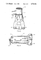
- FIG. 1 is a fragmented perspective view illustrating a vibratory therapy device embodying the novel features of the invention
- FIG. 2 is an exploded perspective view illustrating construction details of a preferred massage head for the vibratory therapy device of FIG. 1;
- FIG. 3 is an enlarged plan view illustrating a preferred fan for use in the vibratory device
- FIG. 4 is a vertical sectional view taken generally on the line 4--4 of FIG. 3;
- FIG. 5 is an enlarged exploded perspective view illustrating an alternative massage head for use in the vibratory device of FIG. 1;
- FIG. 6 is a top plan view of the massage head of FIG. 5;
- FIG. 7 is a fragmented perspective view illustrating an alternative housing configuration for the vibratory device
- FIG. 8 is a fragmented exploded perspective view similar to FIG. 1 and illustrating a further alternative form of a massage head
- FIG. 9 is an enlarged fragmented vertical sectional view taken generally on the line 9--9 of FIG. 8;
- FIG. 10 is a horizontal sectional view taken generally on the line 10--10 of FIG. 9;
- FIG. 11 is a fragmented exploded perspective view illustrating a further alternative form of the invention including a nasal inhalator unit;
- FIG. 12 is a perspective view illustrating a flexible carrying bag utilized as a heat flow concentrating hood or skirt.
- FIG. 13 is a perspective view illustrating the carrying bag with the vibratory device received therein.
- a vibratory therapy device embodying one preferred form of the invention is designated generally by the reference numeral 10 in FIG. 1.
- the vibratory device 10 includes a combination heater/vibrator assembly 12 mounted within a lightweight, portable housing 14 to impart vibratory motion in conjunction with heated air flow to a massage head 16 of selected configuration.
- the particular geometry of the message head is adapted for rapid interchanging to alter the specific therapeutic effects as desired or required by the person receiving massage therapy.
- the improved vibratory therapy device 10 comprises the lightweight housing 14 of illustrative generally cylindrical shape and which is advantageously formed from a lightweight and relatively inexpensive impact-resistant molded plastic or the like.
- the heater/vibrator assembly 12 is mounted within the housing in any suitable manner and includes a lightweight motor 18 for rotatably driving an output shaft 20.
- An air flow fan 22 of lightweight molded plastic or the like is securely mounted upon the output shaft 20 for rotation therewith upon appropriate connection of the motor 18 to a source of electrical power.
- a power cord 24 is shown in FIG. 1 for this purpose and may be appropriately connected to an ac or cc power supply, as required, with an adjustable theostat 26 being mounted along the power cord 24 to provide a combination on-off switch and to regulate the rotational speed of the motor 18 and fan 22.
- Rotational driving of the air flow fan 22 functions to draw air into the housing 14 through a rearwardly upon air intake 28.
- This air flows through the housing 14 past appropriately mounted heating elements 30 which are also coupled to the power supply through the rheostat 26, whereby the rheostat also regulates heating of the air flow.
- the air flows further through the housing for discharge therefrom through an air outlet 32 shown in FIG. 1 to include a perforated safety screen 34 upon which the massage head 16 is securely mounted. Accordingly, the heated air flow discharged through the air outlet 32 flows in and around the massage head 16.
- An additional safety screen 36 of similar design is normally provided over the air intake 28.
- rotation of the fan 22 also functions to impart vibratory action to the entire device including the massage head 16. More particularly, as shown best in FIGS. 3 and 4, the fan 22 includes a plurality of fan blades carried by a central hub 23 which is unbalanced or eccentrically weighted, for example, by forming the hub 23 with significantly different material thickness on opposite sides of a rotational axis. Accordingly, when the fan 22 is rotated, the unbalanced hub 23 causes a significant vibration of the entire device, wherein this vibration is controlled in frequency and magnitude by appropriate adjustment of the rheostat 26.
- the massage head 16 is rapidly adaptable to provide different massage surface configurations for contact with the skin of a person receiving massage therapy.
- the preferred massage head construction accommodates both rolling and non-rolling massage surface configurations which can be interchanged rapidly without the use of any special tools. Accordingly, the specific nature of the massage surface can be uniquely tailored as desired or required by the person receiving massage therapy.
- the examplary massage head 16 comprises a massage head base 38 of generally cylindrical configuration with a lower end securely mounted by an adhesive or other suitable fastening means onto the air outlet safety screen 34 in a generally centered position.
- this base 38 is hollow and extends upwardly from the safety screen 34 with a gradually increasing cross-sectional size.
- the upper end of the base 38 terminates with an external thread configuration 40 adapted for interchangeable mounting of different massage head elements.
- a roller ball assembly 42 is normally mounted onto the upper end of the massage head base 38 and provides at least one rolling massage surface for smooth, non-wrinkling massaging action with the skin of a person receiving therapy.
- the roller ball assembly 42 comprises a downwardly open and internally threaded ball case 44 for threaded attachment onto the base 38.
- a relatively large roller ball 46 is rollingly supported within the ball case 44 and defines the rolling massage surface.
- the roller ball assembly 42 is adapted in turn for removable mounting of a massage cap which may be provided in alternative forms with different surface textures. That is, as shown in FIG. 2, one massage cap 48 of generally hemispherical construction has a downwardly open and internally threaded geometry for rapid mounting onto the roller ball assembly 42 by means of external threads 43 on the ball case 44. Alternately, the massage cap 48 can be threaded directly onto the upper end of the massage head base 38. In either case, the massage cap 48 has an upwardly presented and generally hemispherical smooth surface configuration defining a smooth non-rolling massage surface for the vibratory device. If desired, however, the massage cap 48 can be interchanged with a similar alternative massage cap 50 differing only in the provision of a rough-surfaced external texture to provide still another massage surface configuration.
- an alternate roller ball assembly 52 may also be provided in addition to or in substitution for the roller ball assembly 42 depicted in FIG. 2. More specifically, the alternate roller ball assembly 52 includes a modified ball case 54 which is downwardly open and internally threaded for rapid attachment to the massage head base 38. The upper end of the modified ball case 54 is defined by a transverse platform 56 supporting a plurality of upstanding ball supports 58 secured thereto and each carrying a relatively small roller ball 60, three of which are depicted in the exemplary drawings. These roller balls 60 thus provide still another configuration for a massage surface which is uniquely adapted to provide contoured rolling action around small or hard-to-reach surface areas of the body, for example, in and around fingers and toes.
- roller balls 60 The therapeutic action of these roller balls 60 is greatly enhanced by providing multiple air flow vents 62 in the platform 56 to accommodate air flow passage upwardly through the base 38 in and around the small roller balls 60.
- external threads 64 on the modified ball case 54 are desirably provided to accommodate rapid mounting of a selected massage cap, such as a massage cap 48 or 50 depicted in FIG. 2.
- the lightweight housing 14 of the vibratory device 10 can be modified, as viewed in FIG. 7, to provide storage capability for additional massage caps or roller ball assemblies when the device is not in use.
- a modified cylindrical housing 14' can be provided to include external threads 66 formed about the air intake 28. The size and shape of these threads can be selected to removably retain one of the massage caps or roller ball assemblies depicted in FIGS. 2, 5, and 6, with other massage caps and/or roller ball assemblies normally secured onto the massage head mounting base 38.
- the device thus supports for storage multiple massage head configurations, with the stored components being removed from the lower end of the housing 14'during use to prevent interference with housing air flow.
- FIGS. 8-10 A further modified form of the invention is shown in FIGS. 8-10 to include a modified mounting base 38'for removably supporting a roller ball assembly 42 or the like.
- the modified mounting base 38' includes a lower wall 68 (FIG. 9) cooperating with an intermediate barrier wall 70 to define a well or chamber 72 within which a supply of a selected medicant 74 can be stored.
- the barrier wall 70 is interrupted by a vertically open gap 76 which is approximately threaded to receive a set screw 78 or the like having a protruding head accessible from the exterior of the mounting base 38'.
- Advancement or retraction of the set screw 78 thus variably opens or closes the gap 76 to regulate medicant flow to the roller ball 46 of the ball assembly 42 during massage action, thereby applying the medicant to the skin of a person receiving massage therapy.
- the set screw 78 can be retracted sufficiently to permit relatively easy refilling of the well 72 with the selected medicant.
- the hollow mounting base 38 as described with respect to FIGS. 1 and 2 can be adapted for receiving a nasal inhalator unit 80 in lieu of the above-described massage surface components.
- this nasal inhalator unit comprises an internally threaded cap 82 for receiving a supply of heated air through the mounting base 38. This heated air flows further into a forward support nozzle 84 at a forward end of the cap 82.
- this support nozzle 84 has a relatively large cross section upstream end and tapers progressively to a small cross section downstream end which in turn is joined to a forwardly extending vented support sleeve 86.
- a standard medicant-containing inhalation tube 88 is adapted for rapid press-fit reception into the support nozzle 84 and support sleeve 86, whereby the heated air flow is directed into the inhalation tube via intake passages 90 and for discharge from the inhalation tube through an exit port 92.
- the heated air flow vaporizes and picks up a portion of the medicant which can then be discharged directly into a person's nasal passage, all in the manner described in applicant's copending application Ser. No. 811,279, now U.S. Pat. No. 4,653,494 which is incorporated by reference herein.
- the nasal inhalator unit 80 permits adaptation of the vibratory therapy device 10 for additional use in providing nasal inhalation therapy.
- the vibratory device 10 is conveniently provided with a flexible carrying bag 94 adapted for the dual functions of transporting the device and providing a heat concentration hood or skirt. More specifically, as viewed in FIG. 12, the upper end of the bag 94 is open and includes a drawstring 96 or the like for secure mounting about a midportion of the housing 14. In this position, the bag drapes as a skirt below the massage head and has an open lower end. Heated air flow from the device is thus concentrated in and about the region of the body being treated. However, when treatment is concluded, the bag 94 can be disassembled from the device and the bag lower end closed by means of buttons 98 or the like. The device 10 and any accessories can then be placed into the bag 94 for transport and/or storage, with the drawstring 96 effectively closing the bag upper end.
- the improved vibratory therapy device 10 of the present invention thus provides a substantial number of rapidly interchangeable massage surface configurations in accordance with the desires and needs of the person receiving massage therapy.
- the vibratory device 10 is relatively simple in construction and lightweight for high portability.
- the non-rolling caps 48 and 50 depicted in FIG. 2 can be mounted within a cap case similar to the ball case 44 for mounting by threads or snap-fit or the like onto the base 38, wherein the cap case supports the non-rolling caps for rotation about a central longitudinal axis of the device. With this arrangement, limited freedom of motion of the caps 48 and 50 is thus permitted.
- the cap 48 can be transparent to define a hollow internal chamber within which novelty items may be installed. Accordingly, no limitation is intended by way of the description and drawings, except as set forth in the appended claims.
Abstract
An improved vibratory therapy device is provided for use in relieving muscular and/or joint discomfort, stress, and the like. The vibratory therapy device comprises a lightweight portable housing encasing a heater/vibrator assembly for imparting vibratory action to a massage head together with heated air flow. A plurality of interchangeable massage heads are disclosed, including, for example, smooth or roughened surface textures, single or multiple roller balls, and the like. Other massage head forms may include a medicant applicator or a nasal inhalator unit. A flexible carrying bag is also provided and optimally can be mounted onto the housing to define a depending skirt for concentrating heat flow against a selected region of a person's body receiving massage therapy.
Description
This application is a continuation-in-part of copending application Ser. No. 794,525, filed Nov. 4, 1985, now abandoned which is in turn a continuation-in-part of copending application Ser. Nos. 701,745, filed Feb. 14, 1985, now U.S. Pat. No. 4,596,565; 702,800, filed Feb. 19, 1985, now abandoned; 719,063, filed Apr. 2, 1985 now U.S. Pat. No. 4,587,959; 757,380, filed July 22, 1985, now U.S. Pat. No. 4,640,284; and 757,381, filed July 22, 1985, now U.S. Pat. No. 4,597,757. In addition, this application is a continuation-in-part of copending application Ser. No. 811,279, filed Dec. 20, 1985, now U.S. Pat. No. 4,653,494.
This invention relates generally to therapeutic devices designed primarily for massage therapy to relieve muscular and/or joint discomfort and the like. More particularly, this invention relates to improved designs for relatively lightweight, portable, and inexpensive vibratory therapy devices.
Vibratory devices in general are known for use in applying vibratory therapy to selected regions of the body. Such devices have typically included a motor-driven vibrator unit for imparting a physically detectable vibratory motion to an externally exposed head which, when placed against the body, can be effective to ease muscular discomfort, stress, and the like. As disclosed and claimed in the above-referenced Ser. Nos. 794,525 and 757,381, such vibratory devices can be combined with a source of heated air flow for providing an enhanced and highly soothing therapeutic effect.
The present invention relates to further improvements in therapeutic vibratory devices to enhance the utility and soothing effects thereof. Moreover, the present invention relates to simplified vibratory device constructions adapted for use in a broad variety of therapeutic applications and adapted to include a plurality of easily interchanged massage heads.
In accordance with the invention, an improved vibratory therapeutic device is provided in the form of a relatively lightweight and highly portable housing encasing a compact heater/vibrator assembly. The heater/vibrator assembly imparts, in operation, a therapeutic vibratory action to the entire device including a removably mounted massage head of selected design. In addition, heated air flow is provided in and around the message head to cooperate with the vibratory action when the massage head is placed against the body for a soothing therapeutic effect.
In one preferred form of the invention, the heater/vibrator assembly comprises a lightweight electric motor or the like encased within the housing for rotatably driving an output shaft carrying an eccentrically weighted fan. Rotational driving of the fan upon appropriate connection of the motor to a suitable electrical power supply results in vibratory motion of the entire device and further produces a flow of air through the housing from an air intake to an air outlet. Heating elements within the housing are provided to heat this air flow for discharge flow through the air outlet to the region in and about the massage head. Control means, such as a rheostat may be provided to regulate air flow rate and discharge temperature.
In one form, the massage head comprises a mounting base secured on the housing generally at the air outlet. This mounting base removably supports a roller ball assembly carrying one or more roller balls for rolling movement over a portion of a person's body being treated. Vents and/or air passages formed in the mounting base and ball assembly may be provided for enhanced air flow action in and about the message head. Alternately, the mounting base can be adapted to contain a supply of a selected medicant for application to the person's body via the roller ball assembly.
One or more massage caps of different surface characteristics such as smooth or rough textured hemispherical caps can be provided for removable mounting onto the mounting base on the roller ball assembly. When so mounted, the selected massage cap provides a non-rolling or statioary massage head configuration which can be moved over the portion of a person's body being treated. When multiple massage caps are provided, a non-selected massage cap can be removably mounted in a storage position at another location on the lightweight housing.
In still another form of the invention, a nasal inhalator unit can be provided for removable mounting onto a hollow massage head mounting base. The nasal inhalator unit includes means for removably supporting a medicant-containing inhalation tube. During opertion, warm air flow from the housing air outlet passes through the nasal inhalator unit, including the nasal inhalation tube to vaporize the medicant and carry same outwardly for direction into a person's nasal passages.
A flexible carrying bag is advantageously included for use in transporting and storing the vibratory device. In a preferred form, the bag includes an upper end adapted to fasten about a midportion of the housing and a lower end which can be opened to permit air flow therethrough. When installed on the housing in this manner, the bag forms a depending skirt draped about the housing to concentrate air flow against a selected portion of the body being treated.
Other features and advantages of the present invention will become more apparent from the following detailed description, taken in conjunction with the accompanying drawing, which illustrate, by way of example, the principles of the invention.
The accompanying drawings illustrate the invention. In such drawings:
FIG. 1 is a fragmented perspective view illustrating a vibratory therapy device embodying the novel features of the invention;
FIG. 2 is an exploded perspective view illustrating construction details of a preferred massage head for the vibratory therapy device of FIG. 1;
FIG. 3 is an enlarged plan view illustrating a preferred fan for use in the vibratory device;
FIG. 4 is a vertical sectional view taken generally on the line 4--4 of FIG. 3;
FIG. 5 is an enlarged exploded perspective view illustrating an alternative massage head for use in the vibratory device of FIG. 1;
FIG. 6 is a top plan view of the massage head of FIG. 5;
FIG. 7 is a fragmented perspective view illustrating an alternative housing configuration for the vibratory device;
FIG. 8 is a fragmented exploded perspective view similar to FIG. 1 and illustrating a further alternative form of a massage head;
FIG. 9 is an enlarged fragmented vertical sectional view taken generally on the line 9--9 of FIG. 8;
FIG. 10 is a horizontal sectional view taken generally on the line 10--10 of FIG. 9;
FIG. 11 is a fragmented exploded perspective view illustrating a further alternative form of the invention including a nasal inhalator unit;
FIG. 12 is a perspective view illustrating a flexible carrying bag utilized as a heat flow concentrating hood or skirt; and
FIG. 13 is a perspective view illustrating the carrying bag with the vibratory device received therein.
As shown in the exemplary drawings, a vibratory therapy device embodying one preferred form of the invention is designated generally by the reference numeral 10 in FIG. 1. The vibratory device 10 includes a combination heater/vibrator assembly 12 mounted within a lightweight, portable housing 14 to impart vibratory motion in conjunction with heated air flow to a massage head 16 of selected configuration. The particular geometry of the message head is adapted for rapid interchanging to alter the specific therapeutic effects as desired or required by the person receiving massage therapy.
As shown best in FIG. 1, the improved vibratory therapy device 10 comprises the lightweight housing 14 of illustrative generally cylindrical shape and which is advantageously formed from a lightweight and relatively inexpensive impact-resistant molded plastic or the like. The heater/vibrator assembly 12 is mounted within the housing in any suitable manner and includes a lightweight motor 18 for rotatably driving an output shaft 20. An air flow fan 22 of lightweight molded plastic or the like is securely mounted upon the output shaft 20 for rotation therewith upon appropriate connection of the motor 18 to a source of electrical power. A power cord 24 is shown in FIG. 1 for this purpose and may be appropriately connected to an ac or cc power supply, as required, with an adjustable theostat 26 being mounted along the power cord 24 to provide a combination on-off switch and to regulate the rotational speed of the motor 18 and fan 22.
Rotational driving of the air flow fan 22 functions to draw air into the housing 14 through a rearwardly upon air intake 28. This air flows through the housing 14 past appropriately mounted heating elements 30 which are also coupled to the power supply through the rheostat 26, whereby the rheostat also regulates heating of the air flow. From the heating elements 30, the air flows further through the housing for discharge therefrom through an air outlet 32 shown in FIG. 1 to include a perforated safety screen 34 upon which the massage head 16 is securely mounted. Accordingly, the heated air flow discharged through the air outlet 32 flows in and around the massage head 16. An additional safety screen 36 of similar design is normally provided over the air intake 28.
In accordance with one primary aspect of the invention, rotation of the fan 22 also functions to impart vibratory action to the entire device including the massage head 16. More particularly, as shown best in FIGS. 3 and 4, the fan 22 includes a plurality of fan blades carried by a central hub 23 which is unbalanced or eccentrically weighted, for example, by forming the hub 23 with significantly different material thickness on opposite sides of a rotational axis. Accordingly, when the fan 22 is rotated, the unbalanced hub 23 causes a significant vibration of the entire device, wherein this vibration is controlled in frequency and magnitude by appropriate adjustment of the rheostat 26.
According to a further primary feature of the invention, the massage head 16 is rapidly adaptable to provide different massage surface configurations for contact with the skin of a person receiving massage therapy. For example, the preferred massage head construction accommodates both rolling and non-rolling massage surface configurations which can be interchanged rapidly without the use of any special tools. Accordingly, the specific nature of the massage surface can be uniquely tailored as desired or required by the person receiving massage therapy.
More specifically, as shown best in FIG. 2, the examplary massage head 16 comprises a massage head base 38 of generally cylindrical configuration with a lower end securely mounted by an adhesive or other suitable fastening means onto the air outlet safety screen 34 in a generally centered position. In the preferred form, this base 38 is hollow and extends upwardly from the safety screen 34 with a gradually increasing cross-sectional size. The upper end of the base 38 terminates with an external thread configuration 40 adapted for interchangeable mounting of different massage head elements.
A roller ball assembly 42 is normally mounted onto the upper end of the massage head base 38 and provides at least one rolling massage surface for smooth, non-wrinkling massaging action with the skin of a person receiving therapy. In particular, as viewed in FIG. 1, the roller ball assembly 42 comprises a downwardly open and internally threaded ball case 44 for threaded attachment onto the base 38. A relatively large roller ball 46 is rollingly supported within the ball case 44 and defines the rolling massage surface.
The roller ball assembly 42 is adapted in turn for removable mounting of a massage cap which may be provided in alternative forms with different surface textures. That is, as shown in FIG. 2, one massage cap 48 of generally hemispherical construction has a downwardly open and internally threaded geometry for rapid mounting onto the roller ball assembly 42 by means of external threads 43 on the ball case 44. Alternately, the massage cap 48 can be threaded directly onto the upper end of the massage head base 38. In either case, the massage cap 48 has an upwardly presented and generally hemispherical smooth surface configuration defining a smooth non-rolling massage surface for the vibratory device. If desired, however, the massage cap 48 can be interchanged with a similar alternative massage cap 50 differing only in the provision of a rough-surfaced external texture to provide still another massage surface configuration.
As shown in FIGS. 5 and 6, an alternate roller ball assembly 52 may also be provided in addition to or in substitution for the roller ball assembly 42 depicted in FIG. 2. More specifically, the alternate roller ball assembly 52 includes a modified ball case 54 which is downwardly open and internally threaded for rapid attachment to the massage head base 38. The upper end of the modified ball case 54 is defined by a transverse platform 56 supporting a plurality of upstanding ball supports 58 secured thereto and each carrying a relatively small roller ball 60, three of which are depicted in the exemplary drawings. These roller balls 60 thus provide still another configuration for a massage surface which is uniquely adapted to provide contoured rolling action around small or hard-to-reach surface areas of the body, for example, in and around fingers and toes. The therapeutic action of these roller balls 60 is greatly enhanced by providing multiple air flow vents 62 in the platform 56 to accommodate air flow passage upwardly through the base 38 in and around the small roller balls 60. In addition, external threads 64 on the modified ball case 54 are desirably provided to accommodate rapid mounting of a selected massage cap, such as a massage cap 48 or 50 depicted in FIG. 2.
If desired, the lightweight housing 14 of the vibratory device 10 can be modified, as viewed in FIG. 7, to provide storage capability for additional massage caps or roller ball assemblies when the device is not in use. For example, a modified cylindrical housing 14'can be provided to include external threads 66 formed about the air intake 28. The size and shape of these threads can be selected to removably retain one of the massage caps or roller ball assemblies depicted in FIGS. 2, 5, and 6, with other massage caps and/or roller ball assemblies normally secured onto the massage head mounting base 38. The device thus supports for storage multiple massage head configurations, with the stored components being removed from the lower end of the housing 14'during use to prevent interference with housing air flow.
A further modified form of the invention is shown in FIGS. 8-10 to include a modified mounting base 38'for removably supporting a roller ball assembly 42 or the like. In this form, the modified mounting base 38'includes a lower wall 68 (FIG. 9) cooperating with an intermediate barrier wall 70 to define a well or chamber 72 within which a supply of a selected medicant 74 can be stored. The barrier wall 70 is interrupted by a vertically open gap 76 which is approximately threaded to receive a set screw 78 or the like having a protruding head accessible from the exterior of the mounting base 38'. Advancement or retraction of the set screw 78 thus variably opens or closes the gap 76 to regulate medicant flow to the roller ball 46 of the ball assembly 42 during massage action, thereby applying the medicant to the skin of a person receiving massage therapy. Alternately, the set screw 78 can be retracted sufficiently to permit relatively easy refilling of the well 72 with the selected medicant.
In a still further form of the invention, the hollow mounting base 38 as described with respect to FIGS. 1 and 2 can be adapted for receiving a nasal inhalator unit 80 in lieu of the above-described massage surface components. As shown in FIG. 11, this nasal inhalator unit comprises an internally threaded cap 82 for receiving a supply of heated air through the mounting base 38. This heated air flows further into a forward support nozzle 84 at a forward end of the cap 82. As described in applicant's copending application Ser. No. 811,279, now U.S. Pat. No. 4,653,494, this support nozzle 84 has a relatively large cross section upstream end and tapers progressively to a small cross section downstream end which in turn is joined to a forwardly extending vented support sleeve 86. A standard medicant-containing inhalation tube 88 is adapted for rapid press-fit reception into the support nozzle 84 and support sleeve 86, whereby the heated air flow is directed into the inhalation tube via intake passages 90 and for discharge from the inhalation tube through an exit port 92. During passage through the inhalation tube, the heated air flow vaporizes and picks up a portion of the medicant which can then be discharged directly into a person's nasal passage, all in the manner described in applicant's copending application Ser. No. 811,279, now U.S. Pat. No. 4,653,494 which is incorporated by reference herein. Accordingly, the nasal inhalator unit 80 permits adaptation of the vibratory therapy device 10 for additional use in providing nasal inhalation therapy.
As shown in FIGS. 12 and 13, the vibratory device 10 is conveniently provided with a flexible carrying bag 94 adapted for the dual functions of transporting the device and providing a heat concentration hood or skirt. More specifically, as viewed in FIG. 12, the upper end of the bag 94 is open and includes a drawstring 96 or the like for secure mounting about a midportion of the housing 14. In this position, the bag drapes as a skirt below the massage head and has an open lower end. Heated air flow from the device is thus concentrated in and about the region of the body being treated. However, when treatment is concluded, the bag 94 can be disassembled from the device and the bag lower end closed by means of buttons 98 or the like. The device 10 and any accessories can then be placed into the bag 94 for transport and/or storage, with the drawstring 96 effectively closing the bag upper end.
The improved vibratory therapy device 10 of the present invention thus provides a substantial number of rapidly interchangeable massage surface configurations in accordance with the desires and needs of the person receiving massage therapy. The vibratory device 10 is relatively simple in construction and lightweight for high portability.
A variety of further modifications and improvements to the invention described herein are believed to be apparent to those skilled in the art. For example, if desired, the non-rolling caps 48 and 50 depicted in FIG. 2 can be mounted within a cap case similar to the ball case 44 for mounting by threads or snap-fit or the like onto the base 38, wherein the cap case supports the non-rolling caps for rotation about a central longitudinal axis of the device. With this arrangement, limited freedom of motion of the caps 48 and 50 is thus permitted. Moreover, if desired, the cap 48 can be transparent to define a hollow internal chamber within which novelty items may be installed. Accordingly, no limitation is intended by way of the description and drawings, except as set forth in the appended claims.
Claims (8)
1. A vibratory therapeutic device, comprising:
a housing having air intake and discharge openings formed therein;
a vibrator assembly mounted generally within said housing;
a massage head disposed outside said housing and vibrated by said vibrator assembly; and
means for supplying a flow of heated air into and around said massage head, said heated air flow supplying means including heating means within said housing and fan means for drawing air into said housing through said air intake opening for flow past heating relation with said heating means to elevate the temperature of the air, and for discharging the air from said housing through said air discharge opening;
said massage head including a mounting base secured to said housing and including means for removably supporting a massage member including a roller ball assembly having a ball case mounted upon said mounting base and a roller ball defining a massage surface carried by said ball case, said roller ball being for engagement with the body of a person receiving massage therapy, said mounting base and said ball case cooperatively defining a passage for flow of a portion of the air discharged from said housing through said discharge opening into said mounting base and further into contact with said roller ball while the remaining air is discharged adjacent to said massage head.
2. The device of claim 1 wherein said vibratory assembly and said air flow supply means collectively comprise a motor within said housing for rotationally driving an output shaft, said fan means including an unbalanced fan on said output shaft and rotatable therewith to vibrate the entire device and to create a flow of air between said housing intake opening and said housing discharge opening, and said heating means including heating elements within said housing for elevating the temperature of said air flow, said mounting base being secured to said housing generally at said housing discharge opening.
3. The device of claim 2 further including a rheostat for controlling operation of said motor and said heating elements.
4. The device of claim 1 further including a generally hemispherical cap for removable mounting onto said ball case over said roller ball, said cap defining a further massage surface.
5. The device of claim 4 further including a plurality of generally hemispherical caps each for removable mounting onto said ball case over said roller ball and respectively defining additional massage surfaces of different surface characteristics.
6. The device of claim 1 wherein said ball case is removably mounted on said mounting base and further including a plruality of massage members in addition to said roller ball for interchangeably mounting onto said mounting base.
7. The device of claim 6 wherein said plurality of massage members include a plurality of caps each of generally rounded shape and having massage surfaces of different surface characteristics.
8. The device of claim 1 further including a flexible bag including first means and second means for respectively closing opposite ends thereof, said bag being sized and shaped for receiving and carrying said housing with said first and second means in closed positions, said first means being adapted for removably mounting the associated end of said bag about a midportion of said housing with the opposite bag end draped about and extending beyond the massage head and with said second means in an open position whereby said bag forms a hood for concentrating the heated air flow in the region of the body portion receiving massage therapy.
Priority Applications (10)
| Application Number | Priority Date | Filing Date | Title |
|---|---|---|---|
| US06/817,697 US4722326A (en) | 1985-11-04 | 1986-01-13 | Vibratory therapeutic device |
| EP86900992A EP0211867A1 (en) | 1985-02-14 | 1986-02-04 | Vibratory therapeutic applicator |
| PCT/US1986/000216 WO1986004809A1 (en) | 1985-02-14 | 1986-02-04 | Vibratory therapeutic applicator |
| AU53573/86A AU5357386A (en) | 1985-02-14 | 1986-02-04 | Vibratory therapeutic applicator |
| BR8605553A BR8605553A (en) | 1985-02-14 | 1986-02-04 | VIBRATORY APPLICATOR |
| CN198686101310A CN86101310A (en) | 1985-02-14 | 1986-02-06 | Tremulor |
| FI864043A FI864043A0 (en) | 1985-02-14 | 1986-10-06 | VIBRATOR MASSAGEAPPARAT. |
| DK479586A DK479586A (en) | 1985-02-14 | 1986-10-08 | VIBRATING THERAPEUTIC DEVICE |
| NO864072A NO864072L (en) | 1985-02-14 | 1986-10-13 | VIBRASJONSAPPLIKATOR. |
| KR1019860700714A KR870700338A (en) | 1985-02-14 | 1986-10-14 | Vibration therapy massager |
Applications Claiming Priority (2)
| Application Number | Priority Date | Filing Date | Title |
|---|---|---|---|
| US79452585A | 1985-11-04 | 1985-11-04 | |
| US06/817,697 US4722326A (en) | 1985-11-04 | 1986-01-13 | Vibratory therapeutic device |
Related Parent Applications (6)
| Application Number | Title | Priority Date | Filing Date |
|---|---|---|---|
| US06702800 Continuation-In-Part | 1985-02-19 | ||
| US06/719,063 Continuation-In-Part US4587959A (en) | 1985-04-02 | 1985-04-02 | Hot and cold therapeutic applicator |
| US06/757,381 Continuation-In-Part US4597757A (en) | 1985-02-14 | 1985-07-22 | Heat and salve applicator |
| US06/757,380 Continuation-In-Part US4640284A (en) | 1985-02-14 | 1985-07-22 | Hot and cold direct contact applicator |
| US79452585A Continuation-In-Part | 1985-02-14 | 1985-11-04 | |
| US06/811,279 Continuation-In-Part US4653494A (en) | 1985-12-20 | 1985-12-20 | Nasal inhalation system |
Publications (1)
| Publication Number | Publication Date |
|---|---|
| US4722326A true US4722326A (en) | 1988-02-02 |
Family
ID=27121513
Family Applications (1)
| Application Number | Title | Priority Date | Filing Date |
|---|---|---|---|
| US06/817,697 Expired - Fee Related US4722326A (en) | 1985-02-14 | 1986-01-13 | Vibratory therapeutic device |
Country Status (1)
| Country | Link |
|---|---|
| US (1) | US4722326A (en) |
Cited By (36)
| Publication number | Priority date | Publication date | Assignee | Title |
|---|---|---|---|---|
| US5086788A (en) * | 1988-06-13 | 1992-02-11 | Castel John C | Hand-held physiological stimulation applicator |
| US5097828A (en) * | 1990-09-25 | 1992-03-24 | Richard Deutsch | Thermoelectric therapy device |
| US5172692A (en) * | 1990-12-05 | 1992-12-22 | Kulow Howard H | Method for inflammatory response management |
| WO1994004116A1 (en) * | 1992-08-17 | 1994-03-03 | Mehl Thomas L | Hand-held, multi-purpose portable steamer |
| US5309593A (en) * | 1989-05-16 | 1994-05-10 | Tokyo Copal Chemical Co., Ltd. | Surface finishing device |
| US5336158A (en) * | 1992-11-12 | 1994-08-09 | Huggins Freddie L | Pneumatic vacuum vibrator apparatus |
| US5382222A (en) * | 1992-12-09 | 1995-01-17 | Yih-Jong; Chang | Massaging device |
| USD378539S (en) * | 1995-12-20 | 1997-03-18 | Scott Robert L | Massager |
| US5928170A (en) * | 1997-12-30 | 1999-07-27 | Garrigan; Russell | Audio-enhanced sexual vibrator |
| US6090085A (en) * | 1991-05-30 | 2000-07-18 | Mehl, Sr.; Thomas L. | Skin moisturizing and buffing device |
| US6511446B1 (en) * | 2001-11-16 | 2003-01-28 | Chia-Hsiung Wu | Message bead with heat application effect |
| US20030125648A1 (en) * | 2003-03-14 | 2003-07-03 | Leason Wendy Zeller | Heater for massage nodes and massage therapy device including same |
| US20040097852A1 (en) * | 2000-11-30 | 2004-05-20 | Boyd William T. | Audio interactive sexual vibrator |
| US20050020947A1 (en) * | 2000-06-09 | 2005-01-27 | Interactve Health, Llc | Warm air massager |
| US6866644B1 (en) | 2002-01-23 | 2005-03-15 | Jonathan Kost | Myotherapy massage device |
| US20050209537A1 (en) * | 2004-03-19 | 2005-09-22 | Gleason J N | Method and apparatus for providing hot and cold massage |
| US20050256432A1 (en) * | 2004-05-13 | 2005-11-17 | Harris Kenneth D Jr | Method and apparatus for providing a modifiable massager |
| US20060047230A1 (en) * | 2004-08-18 | 2006-03-02 | Roger Talish | Non-invasive apparatus and method for vibrational treatment of internal organs |
| US20060084837A1 (en) * | 2004-09-07 | 2006-04-20 | Klearman Jeffrey D | Phallic devices with audio features and related methods |
| US20090036808A1 (en) * | 2005-12-22 | 2009-02-05 | Yong-Ho Ki | Apparatus for head acupressure using air pressure |
| US20120121309A1 (en) * | 2010-11-11 | 2012-05-17 | Chuen Chern Co., Ltd. | Cosmetic applicator with vibration device |
| US20120207532A1 (en) * | 2011-02-10 | 2012-08-16 | Jui-Sheng Ho | Automatic switch for a power circuit usable in a bottle |
| US8801600B2 (en) | 2012-03-14 | 2014-08-12 | Ralph Zipper | Sexual stimulation device using light therapy |
| US20140323931A1 (en) * | 2005-06-02 | 2014-10-30 | Ads & B Investment Fund L.P. | Vibrating device for treating nasal congestion and sinusitis symptoms and method thereof |
| WO2014201120A1 (en) * | 2013-06-11 | 2014-12-18 | Health E Company | Vibrating massage roller |
| US20150297445A1 (en) * | 2014-04-21 | 2015-10-22 | Charles R. Gordon, in his capacity as trustee of the Charles Gordon Trust | Neuronal interference devices |
| US20170225193A1 (en) * | 2012-03-15 | 2017-08-10 | Kds Holding Gmbh | Set for Processing a Light-Curing Material |
| US20170319419A1 (en) * | 2016-05-04 | 2017-11-09 | James F. Smith | Method and apparatus for heated massage therapy |
| CN107595571A (en) * | 2017-01-15 | 2018-01-19 | 深圳爱万工业设计有限公司 | Massage head driving apparatus and the massage device for including the massage head driving apparatus |
| US20180049940A1 (en) * | 2016-08-18 | 2018-02-22 | Young Cannon | Thermal Massage Roller |
| US10130550B2 (en) | 2012-03-14 | 2018-11-20 | Ralph Zipper | Sexual stimulation device using light therapy, vibration and physiological feedback |
| US10182962B2 (en) | 2008-11-06 | 2019-01-22 | Health E Vibrations, Llc | Vibrating massage roller |
| US10413473B2 (en) | 2012-03-14 | 2019-09-17 | Ralph Zipper | Sexual stimulation device using light therapy, vibration and physiological feedback |
| US10449112B2 (en) | 2014-12-03 | 2019-10-22 | Healtch e Vibrations, LLC | Vibrating massage roller |
| US11491076B2 (en) * | 2017-09-21 | 2022-11-08 | Power Massage Products Inc | Protective cover system |
| US20220395424A1 (en) * | 2021-06-09 | 2022-12-15 | Yvette Gutierrez Hilty | Face Massaging Device |
Citations (65)
| Publication number | Priority date | Publication date | Assignee | Title |
|---|---|---|---|---|
| US29613A (en) * | 1860-08-14 | Nail-plate feeder | ||
| US736111A (en) * | 1902-05-14 | 1903-08-11 | Theodor Kautz | Inhaling apparatus. |
| GB190513825A (en) * | 1905-07-05 | 1906-04-05 | Otto Emil Muschik | Appliance for Face Massage. |
| US900602A (en) * | 1907-09-03 | 1908-10-06 | William Gentry Shelton | Massage-vibrator. |
| US1262669A (en) * | 1917-01-30 | 1918-04-16 | Hyakutaro Hirota | Massage device. |
| US1697080A (en) * | 1925-12-18 | 1929-01-01 | Oppenheimer Herbert | Method and apparatus for promoting osmotic absorption |
| CH135345A (en) * | 1927-08-27 | 1929-09-15 | Josef Dr Thenen | Apparatus for the combined treatment of the human body with heat and massage. |
| US1772501A (en) * | 1927-01-19 | 1930-08-12 | Donald C Shelton | Scalp-treating apparatus |
| DE517776C (en) * | 1929-09-24 | 1931-02-07 | Paul Steffeck Dr | Device for kneading massage |
| FR704302A (en) * | 1930-10-24 | 1931-05-18 | Roller massager | |
| US1819123A (en) * | 1929-07-30 | 1931-08-18 | Roy M Wolvin | Electrical vaporizer |
| US1825118A (en) * | 1929-06-01 | 1931-09-29 | Jaeg Joseph | Device for keeping warm and damp compresses for local bodily treatment |
| US1856811A (en) * | 1931-07-11 | 1932-05-03 | Hooichi Sumida | Nasal irrigator |
| US1886247A (en) * | 1930-12-15 | 1932-11-01 | Elmer K Cole | Cable splice |
| US1899770A (en) * | 1926-06-26 | 1933-02-28 | Oppenheimer Herbert | Method and apparatus for promoting osmotic absorption |
| US1911468A (en) * | 1933-05-30 | Joseph eobiisrsoh | ||
| US1947042A (en) * | 1930-07-10 | 1934-02-13 | William S Glennan | Massage device |
| US1965918A (en) * | 1931-05-19 | 1934-07-10 | Auberger Thomas | Apparatus for massaging purposes |
| US1969042A (en) * | 1930-03-24 | 1934-08-07 | Charles W Senn | Massaging device |
| US2018046A (en) * | 1931-10-21 | 1935-10-22 | Glenn A Wilson | Vibrator |
| US2048712A (en) * | 1933-06-20 | 1936-07-28 | Adolf P C Schramm | Electric vibrator |
| US2067979A (en) * | 1935-10-03 | 1937-01-19 | Eugene H Cassidy | Therapeutic vibrator |
| US2081034A (en) * | 1935-01-07 | 1937-05-18 | Lionel A Carter | Hair and scalp treating apparatus |
| US2136844A (en) * | 1935-03-19 | 1938-11-15 | Fair | Odor observer and odor meter |
| GB526678A (en) * | 1939-03-21 | 1940-09-24 | Henry William Headland | Improvements in or relating to inhalers and chemical vaporizers |
| US2221972A (en) * | 1938-02-26 | 1940-11-19 | Russell L Jones | Inhalant device |
| US2226582A (en) * | 1936-12-23 | 1940-12-31 | Robinson Joseph | Electrical vaporizer |
| US2249500A (en) * | 1940-02-12 | 1941-07-15 | Vair Corp | Skin cleaning device |
| US2267547A (en) * | 1940-03-18 | 1941-12-23 | Charles E Zimmerman | Facial machine |
| DE718287C (en) * | 1940-12-11 | 1942-03-07 | Fritz Kosakowski | Process for producing low-alcohol or non-alcoholic beverages |
| US2280992A (en) * | 1940-01-08 | 1942-04-28 | Russell M Wright | Apparatus for treating nasal organs |
| US2285105A (en) * | 1939-02-02 | 1942-06-02 | Bacher Ella | Massage apparatus |
| US2426281A (en) * | 1945-08-31 | 1947-08-26 | George W Oakes | Head and nasal clarifier |
| US2451540A (en) * | 1945-09-28 | 1948-10-19 | Frank J Dinyer | Inhaler |
| US2470297A (en) * | 1947-09-04 | 1949-05-17 | Abbott Lab | Inhalator |
| US2574945A (en) * | 1950-04-08 | 1951-11-13 | Aciform Corp | Massage vibrator |
| US2598525A (en) * | 1950-04-08 | 1952-05-27 | E & J Mfg Co | Automatic positive pressure breathing machine |
| US2674994A (en) * | 1952-06-19 | 1954-04-13 | Owen K Murphy | Motor operated kinesitherapy device |
| US2706988A (en) * | 1951-11-19 | 1955-04-26 | Jarolux A G | Human body heat treating apparatus |
| US2739586A (en) * | 1954-04-14 | 1956-03-27 | Preis Oscar Karl | Suction and hot air pressure massage applicator |
| US2787998A (en) * | 1953-05-14 | 1957-04-09 | Grossi Louis | Electrically heated vibratory medicament applicator |
| US3096757A (en) * | 1961-12-18 | 1963-07-09 | Thomas C Berard | Kinesitherapy device |
| US3163166A (en) * | 1961-04-28 | 1964-12-29 | Colgate Palmolive Co | Iontophoresis apparatus |
| US3308268A (en) * | 1959-04-15 | 1967-03-07 | Laing Nikolaus | Portable hair dryers |
| US3370583A (en) * | 1965-02-24 | 1968-02-27 | Teranishi Electric Works | Motor operated massaging vibrator with means for directing air |
| US3481326A (en) * | 1967-04-24 | 1969-12-02 | Charles H M Schamblin | Vibratory hat for scalp massaging |
| US3648368A (en) * | 1970-03-23 | 1972-03-14 | Gillette Co | Safety razor |
| US3710785A (en) * | 1970-11-27 | 1973-01-16 | Ass Mills Inc | Massager |
| US3752155A (en) * | 1972-01-04 | 1973-08-14 | W Blinoff | Apparatus for heating or cooling a surface while simultaneously dispensing a liquid product thereon |
| US3861364A (en) * | 1971-10-06 | 1975-01-21 | Herman Greenfeld | Body circulation and vapor heat treatment device |
| DE2502821A1 (en) * | 1975-01-24 | 1976-07-29 | Dieter W Liedtke | Electric hair dryer with electrically driven comb - for use by professional hairdressers and in home has exchangeable comb on hexagonal hollow shaft |
| US4025809A (en) * | 1975-03-18 | 1977-05-24 | Kabushiki Kaisha Teranishi Denki Seisakusho | Massaging vibrator |
| US4111567A (en) * | 1976-02-11 | 1978-09-05 | Bristol-Myers Company | Liquid applicator |
| DE2749883A1 (en) * | 1977-11-08 | 1979-05-10 | Metronic Elektrogeraete Gmbh | HAND MASSAGER |
| US4173231A (en) * | 1976-10-30 | 1979-11-06 | Matsushita Electric Works, Ltd. | Hair dryer attachment |
| US4248218A (en) * | 1978-09-22 | 1981-02-03 | Fischer Charles M | Gas administration scavenging mask |
| GB2082124A (en) * | 1980-08-12 | 1982-03-03 | Int Chem Co Ltd | Roll-on dispensing device |
| US4365426A (en) * | 1980-01-11 | 1982-12-28 | Hitachi, Ltd. | Hair dryer |
| US4367735A (en) * | 1979-12-31 | 1983-01-11 | Novametrix Medical Systems, Inc. | Nasal cannula |
| DE3139848A1 (en) * | 1981-10-07 | 1983-04-21 | Nanny 7500 Karlsruhe Imhoff | Flat-iron massage appliance |
| US4399349A (en) * | 1981-03-30 | 1983-08-16 | Clairol Inc. | Electrically heated facial sauna appliance |
| US4403611A (en) * | 1980-07-17 | 1983-09-13 | Babbitt Gerald J | Sinus evacuator apparatus |
| US4430808A (en) * | 1981-04-30 | 1984-02-14 | Matsushita Electric Works, Ltd. | Hair dryer |
| US4468221A (en) * | 1981-04-10 | 1984-08-28 | Parker-Hannifin Corporation | Medication infusion pump |
| US4523589A (en) * | 1983-06-29 | 1985-06-18 | Krauser Robert S | Method and apparatus for treating ailments |
-
1986
- 1986-01-13 US US06/817,697 patent/US4722326A/en not_active Expired - Fee Related
Patent Citations (65)
| Publication number | Priority date | Publication date | Assignee | Title |
|---|---|---|---|---|
| US29613A (en) * | 1860-08-14 | Nail-plate feeder | ||
| US1911468A (en) * | 1933-05-30 | Joseph eobiisrsoh | ||
| US736111A (en) * | 1902-05-14 | 1903-08-11 | Theodor Kautz | Inhaling apparatus. |
| GB190513825A (en) * | 1905-07-05 | 1906-04-05 | Otto Emil Muschik | Appliance for Face Massage. |
| US900602A (en) * | 1907-09-03 | 1908-10-06 | William Gentry Shelton | Massage-vibrator. |
| US1262669A (en) * | 1917-01-30 | 1918-04-16 | Hyakutaro Hirota | Massage device. |
| US1697080A (en) * | 1925-12-18 | 1929-01-01 | Oppenheimer Herbert | Method and apparatus for promoting osmotic absorption |
| US1899770A (en) * | 1926-06-26 | 1933-02-28 | Oppenheimer Herbert | Method and apparatus for promoting osmotic absorption |
| US1772501A (en) * | 1927-01-19 | 1930-08-12 | Donald C Shelton | Scalp-treating apparatus |
| CH135345A (en) * | 1927-08-27 | 1929-09-15 | Josef Dr Thenen | Apparatus for the combined treatment of the human body with heat and massage. |
| US1825118A (en) * | 1929-06-01 | 1931-09-29 | Jaeg Joseph | Device for keeping warm and damp compresses for local bodily treatment |
| US1819123A (en) * | 1929-07-30 | 1931-08-18 | Roy M Wolvin | Electrical vaporizer |
| DE517776C (en) * | 1929-09-24 | 1931-02-07 | Paul Steffeck Dr | Device for kneading massage |
| US1969042A (en) * | 1930-03-24 | 1934-08-07 | Charles W Senn | Massaging device |
| US1947042A (en) * | 1930-07-10 | 1934-02-13 | William S Glennan | Massage device |
| FR704302A (en) * | 1930-10-24 | 1931-05-18 | Roller massager | |
| US1886247A (en) * | 1930-12-15 | 1932-11-01 | Elmer K Cole | Cable splice |
| US1965918A (en) * | 1931-05-19 | 1934-07-10 | Auberger Thomas | Apparatus for massaging purposes |
| US1856811A (en) * | 1931-07-11 | 1932-05-03 | Hooichi Sumida | Nasal irrigator |
| US2018046A (en) * | 1931-10-21 | 1935-10-22 | Glenn A Wilson | Vibrator |
| US2048712A (en) * | 1933-06-20 | 1936-07-28 | Adolf P C Schramm | Electric vibrator |
| US2081034A (en) * | 1935-01-07 | 1937-05-18 | Lionel A Carter | Hair and scalp treating apparatus |
| US2136844A (en) * | 1935-03-19 | 1938-11-15 | Fair | Odor observer and odor meter |
| US2067979A (en) * | 1935-10-03 | 1937-01-19 | Eugene H Cassidy | Therapeutic vibrator |
| US2226582A (en) * | 1936-12-23 | 1940-12-31 | Robinson Joseph | Electrical vaporizer |
| US2221972A (en) * | 1938-02-26 | 1940-11-19 | Russell L Jones | Inhalant device |
| US2285105A (en) * | 1939-02-02 | 1942-06-02 | Bacher Ella | Massage apparatus |
| GB526678A (en) * | 1939-03-21 | 1940-09-24 | Henry William Headland | Improvements in or relating to inhalers and chemical vaporizers |
| US2280992A (en) * | 1940-01-08 | 1942-04-28 | Russell M Wright | Apparatus for treating nasal organs |
| US2249500A (en) * | 1940-02-12 | 1941-07-15 | Vair Corp | Skin cleaning device |
| US2267547A (en) * | 1940-03-18 | 1941-12-23 | Charles E Zimmerman | Facial machine |
| DE718287C (en) * | 1940-12-11 | 1942-03-07 | Fritz Kosakowski | Process for producing low-alcohol or non-alcoholic beverages |
| US2426281A (en) * | 1945-08-31 | 1947-08-26 | George W Oakes | Head and nasal clarifier |
| US2451540A (en) * | 1945-09-28 | 1948-10-19 | Frank J Dinyer | Inhaler |
| US2470297A (en) * | 1947-09-04 | 1949-05-17 | Abbott Lab | Inhalator |
| US2574945A (en) * | 1950-04-08 | 1951-11-13 | Aciform Corp | Massage vibrator |
| US2598525A (en) * | 1950-04-08 | 1952-05-27 | E & J Mfg Co | Automatic positive pressure breathing machine |
| US2706988A (en) * | 1951-11-19 | 1955-04-26 | Jarolux A G | Human body heat treating apparatus |
| US2674994A (en) * | 1952-06-19 | 1954-04-13 | Owen K Murphy | Motor operated kinesitherapy device |
| US2787998A (en) * | 1953-05-14 | 1957-04-09 | Grossi Louis | Electrically heated vibratory medicament applicator |
| US2739586A (en) * | 1954-04-14 | 1956-03-27 | Preis Oscar Karl | Suction and hot air pressure massage applicator |
| US3308268A (en) * | 1959-04-15 | 1967-03-07 | Laing Nikolaus | Portable hair dryers |
| US3163166A (en) * | 1961-04-28 | 1964-12-29 | Colgate Palmolive Co | Iontophoresis apparatus |
| US3096757A (en) * | 1961-12-18 | 1963-07-09 | Thomas C Berard | Kinesitherapy device |
| US3370583A (en) * | 1965-02-24 | 1968-02-27 | Teranishi Electric Works | Motor operated massaging vibrator with means for directing air |
| US3481326A (en) * | 1967-04-24 | 1969-12-02 | Charles H M Schamblin | Vibratory hat for scalp massaging |
| US3648368A (en) * | 1970-03-23 | 1972-03-14 | Gillette Co | Safety razor |
| US3710785A (en) * | 1970-11-27 | 1973-01-16 | Ass Mills Inc | Massager |
| US3861364A (en) * | 1971-10-06 | 1975-01-21 | Herman Greenfeld | Body circulation and vapor heat treatment device |
| US3752155A (en) * | 1972-01-04 | 1973-08-14 | W Blinoff | Apparatus for heating or cooling a surface while simultaneously dispensing a liquid product thereon |
| DE2502821A1 (en) * | 1975-01-24 | 1976-07-29 | Dieter W Liedtke | Electric hair dryer with electrically driven comb - for use by professional hairdressers and in home has exchangeable comb on hexagonal hollow shaft |
| US4025809A (en) * | 1975-03-18 | 1977-05-24 | Kabushiki Kaisha Teranishi Denki Seisakusho | Massaging vibrator |
| US4111567A (en) * | 1976-02-11 | 1978-09-05 | Bristol-Myers Company | Liquid applicator |
| US4173231A (en) * | 1976-10-30 | 1979-11-06 | Matsushita Electric Works, Ltd. | Hair dryer attachment |
| DE2749883A1 (en) * | 1977-11-08 | 1979-05-10 | Metronic Elektrogeraete Gmbh | HAND MASSAGER |
| US4248218A (en) * | 1978-09-22 | 1981-02-03 | Fischer Charles M | Gas administration scavenging mask |
| US4367735A (en) * | 1979-12-31 | 1983-01-11 | Novametrix Medical Systems, Inc. | Nasal cannula |
| US4365426A (en) * | 1980-01-11 | 1982-12-28 | Hitachi, Ltd. | Hair dryer |
| US4403611A (en) * | 1980-07-17 | 1983-09-13 | Babbitt Gerald J | Sinus evacuator apparatus |
| GB2082124A (en) * | 1980-08-12 | 1982-03-03 | Int Chem Co Ltd | Roll-on dispensing device |
| US4399349A (en) * | 1981-03-30 | 1983-08-16 | Clairol Inc. | Electrically heated facial sauna appliance |
| US4468221A (en) * | 1981-04-10 | 1984-08-28 | Parker-Hannifin Corporation | Medication infusion pump |
| US4430808A (en) * | 1981-04-30 | 1984-02-14 | Matsushita Electric Works, Ltd. | Hair dryer |
| DE3139848A1 (en) * | 1981-10-07 | 1983-04-21 | Nanny 7500 Karlsruhe Imhoff | Flat-iron massage appliance |
| US4523589A (en) * | 1983-06-29 | 1985-06-18 | Krauser Robert S | Method and apparatus for treating ailments |
Cited By (48)
| Publication number | Priority date | Publication date | Assignee | Title |
|---|---|---|---|---|
| US5086788A (en) * | 1988-06-13 | 1992-02-11 | Castel John C | Hand-held physiological stimulation applicator |
| US5309593A (en) * | 1989-05-16 | 1994-05-10 | Tokyo Copal Chemical Co., Ltd. | Surface finishing device |
| US5097828A (en) * | 1990-09-25 | 1992-03-24 | Richard Deutsch | Thermoelectric therapy device |
| US5172692A (en) * | 1990-12-05 | 1992-12-22 | Kulow Howard H | Method for inflammatory response management |
| US6090085A (en) * | 1991-05-30 | 2000-07-18 | Mehl, Sr.; Thomas L. | Skin moisturizing and buffing device |
| WO1994004116A1 (en) * | 1992-08-17 | 1994-03-03 | Mehl Thomas L | Hand-held, multi-purpose portable steamer |
| US5336158A (en) * | 1992-11-12 | 1994-08-09 | Huggins Freddie L | Pneumatic vacuum vibrator apparatus |
| US5382222A (en) * | 1992-12-09 | 1995-01-17 | Yih-Jong; Chang | Massaging device |
| USD378539S (en) * | 1995-12-20 | 1997-03-18 | Scott Robert L | Massager |
| US5928170A (en) * | 1997-12-30 | 1999-07-27 | Garrigan; Russell | Audio-enhanced sexual vibrator |
| US7238162B2 (en) | 2000-06-09 | 2007-07-03 | Human Touch, Llc | Warm air massager |
| US20050020947A1 (en) * | 2000-06-09 | 2005-01-27 | Interactve Health, Llc | Warm air massager |
| US20040097852A1 (en) * | 2000-11-30 | 2004-05-20 | Boyd William T. | Audio interactive sexual vibrator |
| US6511446B1 (en) * | 2001-11-16 | 2003-01-28 | Chia-Hsiung Wu | Message bead with heat application effect |
| US6866644B1 (en) | 2002-01-23 | 2005-03-15 | Jonathan Kost | Myotherapy massage device |
| US6866776B2 (en) * | 2003-03-14 | 2005-03-15 | Wendy Zeller Leason | Heater for massage nodes and massage therapy device including same |
| US20030125648A1 (en) * | 2003-03-14 | 2003-07-03 | Leason Wendy Zeller | Heater for massage nodes and massage therapy device including same |
| US20050209537A1 (en) * | 2004-03-19 | 2005-09-22 | Gleason J N | Method and apparatus for providing hot and cold massage |
| US7211057B2 (en) | 2004-03-19 | 2007-05-01 | Brookstone Purchasing | Method and apparatus for providing hot and cold massage |
| US20050256432A1 (en) * | 2004-05-13 | 2005-11-17 | Harris Kenneth D Jr | Method and apparatus for providing a modifiable massager |
| US7427274B2 (en) | 2004-05-13 | 2008-09-23 | Brookstone Purchasing, Inc. | Method and apparatus for providing a modifiable massager |
| US20060047230A1 (en) * | 2004-08-18 | 2006-03-02 | Roger Talish | Non-invasive apparatus and method for vibrational treatment of internal organs |
| US7946977B2 (en) | 2004-09-07 | 2011-05-24 | My Little Secret, Llc | Phallic devices with audio features and related methods |
| US20060084837A1 (en) * | 2004-09-07 | 2006-04-20 | Klearman Jeffrey D | Phallic devices with audio features and related methods |
| US20140323931A1 (en) * | 2005-06-02 | 2014-10-30 | Ads & B Investment Fund L.P. | Vibrating device for treating nasal congestion and sinusitis symptoms and method thereof |
| US10022511B2 (en) * | 2005-06-02 | 2018-07-17 | Ads & B Investment Fund L.P. | Vibrating device for treating nasal congestion and sinusitis symptoms and method thereof |
| US20090036808A1 (en) * | 2005-12-22 | 2009-02-05 | Yong-Ho Ki | Apparatus for head acupressure using air pressure |
| US10285901B2 (en) | 2008-11-06 | 2019-05-14 | Health E Vibrations, Llc | Vibrating massage roller |
| US10182962B2 (en) | 2008-11-06 | 2019-01-22 | Health E Vibrations, Llc | Vibrating massage roller |
| US20120121309A1 (en) * | 2010-11-11 | 2012-05-17 | Chuen Chern Co., Ltd. | Cosmetic applicator with vibration device |
| US20120207532A1 (en) * | 2011-02-10 | 2012-08-16 | Jui-Sheng Ho | Automatic switch for a power circuit usable in a bottle |
| US8591133B2 (en) * | 2011-02-10 | 2013-11-26 | Jui-Sheng Ho | Automatic switch for a power circuit usable in a bottle |
| US10940080B2 (en) | 2012-03-14 | 2021-03-09 | Ralph Zipper | Method for sexual stimulation |
| US10413473B2 (en) | 2012-03-14 | 2019-09-17 | Ralph Zipper | Sexual stimulation device using light therapy, vibration and physiological feedback |
| US9610214B2 (en) | 2012-03-14 | 2017-04-04 | Ralph Zipper | Sexual stimulation method using light therapy |
| US8801600B2 (en) | 2012-03-14 | 2014-08-12 | Ralph Zipper | Sexual stimulation device using light therapy |
| US10130550B2 (en) | 2012-03-14 | 2018-11-20 | Ralph Zipper | Sexual stimulation device using light therapy, vibration and physiological feedback |
| US20170225193A1 (en) * | 2012-03-15 | 2017-08-10 | Kds Holding Gmbh | Set for Processing a Light-Curing Material |
| US10173239B2 (en) * | 2012-03-15 | 2019-01-08 | Kds Holding Gmbh | Set for processing a light-curing material |
| WO2014201120A1 (en) * | 2013-06-11 | 2014-12-18 | Health E Company | Vibrating massage roller |
| US20150297445A1 (en) * | 2014-04-21 | 2015-10-22 | Charles R. Gordon, in his capacity as trustee of the Charles Gordon Trust | Neuronal interference devices |
| US10449112B2 (en) | 2014-12-03 | 2019-10-22 | Healtch e Vibrations, LLC | Vibrating massage roller |
| US20170319419A1 (en) * | 2016-05-04 | 2017-11-09 | James F. Smith | Method and apparatus for heated massage therapy |
| US10849812B2 (en) * | 2016-05-04 | 2020-12-01 | James F. Smith | Method and apparatus for heated massage therapy |
| US20180049940A1 (en) * | 2016-08-18 | 2018-02-22 | Young Cannon | Thermal Massage Roller |
| CN107595571A (en) * | 2017-01-15 | 2018-01-19 | 深圳爱万工业设计有限公司 | Massage head driving apparatus and the massage device for including the massage head driving apparatus |
| US11491076B2 (en) * | 2017-09-21 | 2022-11-08 | Power Massage Products Inc | Protective cover system |
| US20220395424A1 (en) * | 2021-06-09 | 2022-12-15 | Yvette Gutierrez Hilty | Face Massaging Device |
Similar Documents
| Publication | Publication Date | Title |
|---|---|---|
| US4722326A (en) | Vibratory therapeutic device | |
| US20200261306A1 (en) | Handheld massage device | |
| US7238162B2 (en) | Warm air massager | |
| US6758826B2 (en) | Vibrating personal massager | |
| US20170304145A1 (en) | Handheld massage device | |
| WO1986004809A1 (en) | Vibratory therapeutic applicator | |
| US6261251B1 (en) | J-shaped massage device having a vibrator | |
| US6405390B2 (en) | Multifunctional foot spa | |
| US6958046B2 (en) | Chest compression apparatus | |
| EP1359880B1 (en) | Spa capsule | |
| US4157088A (en) | Audio relaxer-massager | |
| WO2009013742A1 (en) | Massager | |
| US6589192B2 (en) | Deep tissue massage machine | |
| WO2005035038A1 (en) | Spa capsule | |
| JPS62500987A (en) | therapeutic vibrator | |
| US6839982B1 (en) | Dryer and atomized medicinal liquid apparatus for feet with shoe drying attachment | |
| CN211750941U (en) | Ultrasonic medicine applying and massaging device capable of delaying medicine and heat loss | |
| WO2020140131A1 (en) | Portable sauna device with herbal essential oils | |
| JPH02268762A (en) | Esthetic apparatus | |
| CN2540176Y (en) | Hand-held hammer masseur | |
| CN215607460U (en) | Gynaecology and obstetrics combines massager with chinese traditional and western medicine | |
| CN213994197U (en) | Traditional chinese medical science is recovered with medicine fumigation apparatus | |
| JPS6317463Y2 (en) | ||
| CN214343381U (en) | Multifunctional Chinese medicine atomizing therapeutic instrument | |
| CN219250944U (en) | Head massage device |
Legal Events
| Date | Code | Title | Description |
|---|---|---|---|
| FEPP | Fee payment procedure |
Free format text: PAYOR NUMBER ASSIGNED (ORIGINAL EVENT CODE: ASPN); ENTITY STATUS OF PATENT OWNER: SMALL ENTITY |
|
| REMI | Maintenance fee reminder mailed | ||
| LAPS | Lapse for failure to pay maintenance fees | ||
| FP | Lapsed due to failure to pay maintenance fee |
Effective date: 19920131 |
|
| STCH | Information on status: patent discontinuation |
Free format text: PATENT EXPIRED DUE TO NONPAYMENT OF MAINTENANCE FEES UNDER 37 CFR 1.362 |