US4900090A - Slat assembled chair and method of assembly thereof - Google Patents
Slat assembled chair and method of assembly thereof Download PDFInfo
- Publication number
- US4900090A US4900090A US07/106,523 US10652387A US4900090A US 4900090 A US4900090 A US 4900090A US 10652387 A US10652387 A US 10652387A US 4900090 A US4900090 A US 4900090A
- Authority
- US
- United States
- Prior art keywords
- plug
- slats
- slat
- socket
- back wall
- Prior art date
- Legal status (The legal status is an assumption and is not a legal conclusion. Google has not performed a legal analysis and makes no representation as to the accuracy of the status listed.)
- Expired - Fee Related
Links
- 238000000034 method Methods 0.000 title description 2
- 239000000463 material Substances 0.000 claims description 5
- 230000002441 reversible effect Effects 0.000 claims 1
- 239000004743 Polypropylene Substances 0.000 description 3
- -1 polypropylene Polymers 0.000 description 3
- 229920001155 polypropylene Polymers 0.000 description 3
- 238000010276 construction Methods 0.000 description 2
- 239000004033 plastic Substances 0.000 description 2
- 229920003002 synthetic resin Polymers 0.000 description 2
- 239000000057 synthetic resin Substances 0.000 description 2
- 238000012986 modification Methods 0.000 description 1
- 230000004048 modification Effects 0.000 description 1
- 230000000284 resting effect Effects 0.000 description 1
- 239000004616 structural foam Substances 0.000 description 1
Images
Classifications
-
- A—HUMAN NECESSITIES
- A47—FURNITURE; DOMESTIC ARTICLES OR APPLIANCES; COFFEE MILLS; SPICE MILLS; SUCTION CLEANERS IN GENERAL
- A47C—CHAIRS; SOFAS; BEDS
- A47C5/00—Chairs of special materials
- A47C5/12—Chairs of special materials of plastics, with or without reinforcement
-
- F—MECHANICAL ENGINEERING; LIGHTING; HEATING; WEAPONS; BLASTING
- F16—ENGINEERING ELEMENTS AND UNITS; GENERAL MEASURES FOR PRODUCING AND MAINTAINING EFFECTIVE FUNCTIONING OF MACHINES OR INSTALLATIONS; THERMAL INSULATION IN GENERAL
- F16B—DEVICES FOR FASTENING OR SECURING CONSTRUCTIONAL ELEMENTS OR MACHINE PARTS TOGETHER, e.g. NAILS, BOLTS, CIRCLIPS, CLAMPS, CLIPS OR WEDGES; JOINTS OR JOINTING
- F16B2200/00—Constructional details of connections not covered for in other groups of this subclass
- F16B2200/30—Dovetail-like connections
Definitions
- the invention relates to chairs of the type having transverse slats connected at their ends to opposing side rails supported on suitable legs, the slats forming the chair seat or chair back or both.
- the invention may advantageously be utilized with the type of furniture known as lawn or patio furniture, including chairs, chaise longues and the like. It has been customary to mold such chairs out of synthetic resin such as polypropylene. Most prior chairs are usually molded in one piece, but the required molds are not only large, heavy and unwieldy, but also very expensive. Moreover, shipping the one-piece chairs is laborious and expensive.
- the present invention provides lightweight plastic slats detachably connected and interlocked at their ends to laterally spaced opposed side rails.
- Prior detachable joints between plastic parts have been difficult for the ordinary user to attach and detach in addition to being difficult and expensive to mold. Also, such joints are prone to become unsecured under stress.
- Another object is to provide a novel and improved chair having transverse slats resiliently interlocked with the side rails by a snap-in action.
- a further object is to provide an improved detachable joint having novel interfitting plug and socket elements connecting the slats and side rails, which joint is economically and easily molded.
- a still further object is to provide a novel and improved chair having parts which are inexpensive to mold and transport and readily assembled and disassembled by the ultimate user without the use of tools or separate fasteners.
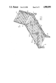
- FIG. 1 is a perspective view of a chaise longue type of chair embodying the present invention.
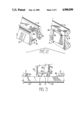
- FIG. 2 is an exploded enlarged view showing fragmentarily one embodiment of the novel plug and socket parts mounted on a side rail and one end of a juxtaposed slat.
- FIG. 3 is a fragmentary bottom plan view showing the end of a slat connected to a side rail by the novel plug and socket joint.
- FIG. 4a is a fragmentary cross-sectional view showing the novel end socket of a slat partially engaged with a plug on a side rail.
- FIG. 4b is a similar view showing the socket and plug fully engaged.
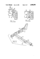
- FIG. 5 is an enlarged exploded perspective view of the first embodiment, showing the inner side of a side rail and one of the slats in juxtaposed position.
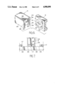
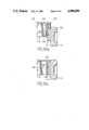
- FIG. 6 is an exploded enlarged view similar to FIG. 2, showing fragmentarily an alternate embodiment of the novel plug and socket parts mounted on a side rail and one end of a juxtaposed slat.
- FIG. 7 is a bottom plan view similar to FIG. 3, showing the plug and socket parts of the alternate embodiment fully connected.
- FIG. 8a is a fragmentary cross-sectional view similar to FIG. 4a, showing the plug and socket parts of the alternate embodiment partially connected.
- FIG. 8b is a similar view, showing the plug and socket parts of the alternate embodiment fully engaged.
- the chaise longue chair shown in FIG. 1 has a seat portion indicated generally at 10 having supporting legs 11 attached to side rails 12 with a plurality of transverse slats 13 connecting the side rails.
- the chair also includes an inclined back portion indicated generally at 14 having side rails 15 suitably attached to the side rails 12 and having additional transverse slats 13 connecting the side rails 15.
- the rails, legs and slats are molded of synthetic resin material formulated to provide substantial rigidity to the legs 11 and side rails 12 and 15, and to provide a certain amount of resilience to the slats 13 for purposes to be described.
- Polypropylene is suitable for this purpose.
- side rails 12 and 15 are molded separately from slats 13, an advantage of this invention is that they may be made of different materials.
- side rails 12 and 15 may be made of a more rigid material than slats 13, such as structural foam, with slats 13 being made, for comfort, of the more resilient polypropylene.
- the slats are preferably generally of inverted U-shape in cross-section, and the upper webs thereof may be slightly dished to further enhance the comfort of a person resting thereon.
- side rails 12 and 15 in one preferred embodiment are provided along their inner surfaces with longitudinal rows of uniformly spaced projections or plugs 17.
- These plugs are preferably generally rectangular with curved upper edges 18 and flat inner surfaces 19.
- Each plug has a groove 20 extending continuously around its upper and side edges.
- each slat The ends of each slat are provided with sockets for slidably receiving the plugs.
- Each socket indicated generally at 22, has an inverted U-shape formed by end extensions of the top web 23 and side walls 24 of the slat.
- Inturned ribs 25 are formed on the end of each socket and these ribs 25 are adapted to be slidably received in the side portions of groove 20 of a plug 17, thereby preventing relative movement transversely of the side rail.
- the back of each socket is closed by a thin resilient wall 26 spaced inwardly of the ribs 25 and adapted to slidably abut the flat surface 19 of the plug. At the bottom edge of wall 26 on the surface facing outwardly of each socket 22, a short narrow rib 27 is formed.
- each slat 13 is abutted against the inner surfaces 28 of the opposing side rails 12 around and above the plugs 17 to be slidably engaged.
- the ends of the slat are then pushed downwardly forcing each rib 27 to cam over the upper edge 29 of the plug by flexing the wall 26 causing the ribs 25 to slidably enter the side portions of the groove 20, as shown in FIG. 4a.
- the end extension forming the top wall of the socket abuts the upper edge of the plug, the rib 27 snaps under the bottom edge of the plug, as shown in FIG. 4b, due to the resilience of the wall 26, thus interlocking the slat with the side rail.
- Disassembly can be easily and quickly accomplished by bumping the underside sides of the ends of the slats upwardly, causing the ribs 27 to cam over the bottom edges of the plugs and flexing the resilient walls 26 of the sockets to quickly slide the ends of the slats free of the rails, again without the need of any tools or of loosening fasteners.
- the rib 27 may be slightly rounded to facilitate the camming action as it snaps into and out of engagement with the plug.
- the side rails 12 and 15 of the alternate embodiment are provided along their inner surfaces with longitudinal rows of longitudinally spaced projections or plugs 117.
- These plugs are preferably rectangular with flat inner surfaces 119.
- Each plug has vertical side grooves 120 extending continuously along its side edges.
- each slat The ends of each slat are provided with sockets indicated generally at 122 for slidably receiving the plugs 117.
- Each socket has an inverted U-shape formed by extensions of the top web 123, and side walls 124 of the slat.
- Inturned vertical ribs 125 are formed on the end of each socket and the ribs 125 are adapted to be slidably received in the side grooves 120 of a plug 117, thereby preventing relative movement transversely of the side rail.
- the back of each socket 120 is closed by a thin resilient wall 126 spaced inwardly of the ribs 125 and adapted to slidably abut the flat surface 119 of the plug.
- each plug 117 Medially of the inner flat surface of each plug 117 is formed a horizontal recess 130 having flat side wall surfaces 131 and 132 perpendicular to the flat inner surface 119 of the plug.
- a projecting horizontal rib 133 adapted to be received in said recess 130 when a slat is pushed downwardly to force a socket 120 over a plug 117, as shown in FIGS. 8a and 8b.
- the rib 133 has a flat upper edge 134 and a beveled lower edge 135 (see FIG. 6) so that as the slat is pushed downwardly the rib slides over the upper edge of the plug 117 as seen in FIG. 8a, and when the extended end forming the top wall of the socket abuts the upper edge of the plug the rib 133 snaps into the recess 130, with its upper edge engaged and interlocked with the upper edge of the recess, as shown in FIG. 8b.
- the sockets could be formed on the side rails and the plugs formed on the ends of the slats while obtaining precisely the same advantageous results.
Abstract
Description
Claims (4)
Priority Applications (3)
| Application Number | Priority Date | Filing Date | Title |
|---|---|---|---|
| US07/106,523 US4900090A (en) | 1987-10-08 | 1987-10-08 | Slat assembled chair and method of assembly thereof |
| AU23404/88A AU616431B2 (en) | 1987-10-08 | 1988-10-04 | Slat assembled chair and method of assembly thereof |
| NZ226474A NZ226474A (en) | 1987-10-08 | 1988-10-06 | Chair with moulded slats interconnected with moulded side rails |
Applications Claiming Priority (1)
| Application Number | Priority Date | Filing Date | Title |
|---|---|---|---|
| US07/106,523 US4900090A (en) | 1987-10-08 | 1987-10-08 | Slat assembled chair and method of assembly thereof |
Publications (1)
| Publication Number | Publication Date |
|---|---|
| US4900090A true US4900090A (en) | 1990-02-13 |
Family
ID=22311867
Family Applications (1)
| Application Number | Title | Priority Date | Filing Date |
|---|---|---|---|
| US07/106,523 Expired - Fee Related US4900090A (en) | 1987-10-08 | 1987-10-08 | Slat assembled chair and method of assembly thereof |
Country Status (3)
| Country | Link |
|---|---|
| US (1) | US4900090A (en) |
| AU (1) | AU616431B2 (en) |
| NZ (1) | NZ226474A (en) |
Cited By (35)
| Publication number | Priority date | Publication date | Assignee | Title |
|---|---|---|---|---|
| US5074081A (en) * | 1991-06-12 | 1991-12-24 | Ryobi Motor Products Corp. | Sander with removable auxiliary handle |
| US5318346A (en) * | 1991-05-30 | 1994-06-07 | Steelcase Inc. | Chair with zero front rise control |
| US5630643A (en) * | 1993-06-01 | 1997-05-20 | Steelcase Inc | Upholstered chair with two-piece shell |
| US5720537A (en) * | 1995-07-07 | 1998-02-24 | Heinrich Lutz | Dovetail joint construction |
| US5996145A (en) * | 1997-10-15 | 1999-12-07 | Harry A. Taylor | Adjustable bed frame system |
| US6109707A (en) * | 1997-03-25 | 2000-08-29 | Sony Corporation | Storage case for recording media |
| US6301942B1 (en) * | 1998-07-24 | 2001-10-16 | Arrow Lock Manufacturing Company | Accessories for a modular removable core cylinder assembly |
| EP1602838A3 (en) * | 2004-05-27 | 2006-05-10 | Harrer Vinzenz | Plug-in connection with stabilizer |
| US20080169680A1 (en) * | 2007-01-11 | 2008-07-17 | Ford Motor Company | Vehicle body assembly |
| US20080169686A1 (en) * | 2007-01-11 | 2008-07-17 | Ford Motor Company | Vehicle having an engine support structure |
| US20080169666A1 (en) * | 2007-01-11 | 2008-07-17 | Ford Motor Company | Vehicle having a body panel |
| US20080169679A1 (en) * | 2007-01-11 | 2008-07-17 | Ford Motor Company | Vehicle having a passenger compartment body structure |
| US20080169685A1 (en) * | 2007-01-11 | 2008-07-17 | Ford Motor Company | Vehicle body component and mating feature |
| US20080169681A1 (en) * | 2007-01-11 | 2008-07-17 | Ford Motor Company | Vehicle having an interlocking floor assembly |
| US20080169682A1 (en) * | 2007-01-11 | 2008-07-17 | Ford Motor Company | Vehicle having a rear end body structure |
| US20080169677A1 (en) * | 2007-01-11 | 2008-07-17 | Ford Motor Company | Vehicle body structure |
| US20080169683A1 (en) * | 2007-01-11 | 2008-07-17 | Ford Motor Company | Vehicle having a front end body structure |
| US20080169660A1 (en) * | 2007-01-11 | 2008-07-17 | Ford Motor Company | Tunable inner fender structure |
| US20080169665A1 (en) * | 2007-01-11 | 2008-07-17 | Ford Motor Company | Vehicle having a passenger compartment body structure |
| US20080168644A1 (en) * | 2007-01-11 | 2008-07-17 | Ford Motor Company | Method of manufacturing a vehicle |
| US20080201952A1 (en) * | 2007-01-11 | 2008-08-28 | Ford Motor Company | Method of manufacturing a vehicle |
| US20090001334A1 (en) * | 2007-06-28 | 2009-01-01 | Off The Wall Products Llc | Control barrier |
| US20140161518A1 (en) * | 2012-07-14 | 2014-06-12 | Kenneth H. KO | Connectors used in modular furniture system |
| US20140231737A1 (en) * | 2011-09-29 | 2014-08-21 | Oxford Plastic Systems Limited | Base for fencing |
| US20140239698A1 (en) * | 2013-01-29 | 2014-08-28 | Billy Joe Griggs, Jr. | Novel cam assembly utilizing 2 or more interconnected and locking parts for furniture |
| US8905670B1 (en) * | 2009-09-30 | 2014-12-09 | Apq Development, Llc | Snap-fit joint for plastic frame elements and frames formed thereby |
| USD738125S1 (en) | 2014-05-12 | 2015-09-08 | Steelcase Inc. | Foot rest |
| US20170071347A1 (en) * | 2014-01-29 | 2017-03-16 | Billy Joe Griggs, Jr. | Novel cam assembly with interlocking parts for furniture |
| US9643266B1 (en) * | 2006-10-27 | 2017-05-09 | Battenfeld Technologies, Inc. | Extendable folding saw |
| US20180355901A1 (en) * | 2017-06-09 | 2018-12-13 | Hni Technologies Inc. | Support beam connector system |
| USD839011S1 (en) | 2017-12-13 | 2019-01-29 | Steelcase Inc. | Ottoman |
| US10539169B2 (en) | 2012-07-14 | 2020-01-21 | Kenneth H. KO | Connectors used in modular furniture system |
| USD911727S1 (en) * | 2016-04-11 | 2021-03-02 | B&B Italia S.P.A. | Chaise-lounge |
| US20220090615A1 (en) * | 2013-01-29 | 2022-03-24 | Billy Joe Griggs, Jr. | Novel cam assembly with interlocking parts for furniture |
| US20220338635A1 (en) * | 2021-04-22 | 2022-10-27 | Honest Structures LLC | Structures with interlocking hems and methods of forming same |
Families Citing this family (1)
| Publication number | Priority date | Publication date | Assignee | Title |
|---|---|---|---|---|
| EP1711084B1 (en) * | 2004-01-27 | 2014-03-05 | G James Extrusion Co. Pty Ltd | Seats or benches with slats |
Citations (13)
| Publication number | Priority date | Publication date | Assignee | Title |
|---|---|---|---|---|
| US609703A (en) * | 1898-08-23 | Stay for bed-slats | ||
| US984823A (en) * | 1910-12-12 | 1911-02-21 | Corry Metal Furniture Company | Sheet-metal bedstead. |
| US1348707A (en) * | 1919-12-13 | 1920-08-03 | Gamble Stanley Benjamin | Post and side bar of beds, furniture, and the like |
| GB273842A (en) * | 1927-01-15 | 1927-07-14 | George Bennet | Improvements relating to joints for connecting the metal parts to the woodwork of school furniture |
| US3074203A (en) * | 1959-04-27 | 1963-01-22 | Paksy Jeno | Toy constructional outfit |
| US3663055A (en) * | 1970-07-10 | 1972-05-16 | Monsanto Co | Chair with adjustable seating portions |
| US4012155A (en) * | 1975-05-02 | 1977-03-15 | Morris Max O | Snap lock connector for components such as knock-down furniture components |
| US4019298A (en) * | 1973-07-18 | 1977-04-26 | Johnson Iv John J | Beam suspension system |
| US4438800A (en) * | 1982-02-25 | 1984-03-27 | Hemmerle Clayton J | Surface defining slats and articles utilizing same |
| FR2549912A1 (en) * | 1983-07-25 | 1985-02-01 | Dunlop Sa | Device for elastically coupling laths to a base |
| US4504168A (en) * | 1981-03-27 | 1985-03-12 | Miller Michael C | Connecting structure |
| US4548590A (en) * | 1983-05-17 | 1985-10-22 | Green Anthony W | Construction element |
| US4550230A (en) * | 1982-10-18 | 1985-10-29 | International Jensen Incorporated | Speaker grille with snap-in fastener system |
Family Cites Families (1)
| Publication number | Priority date | Publication date | Assignee | Title |
|---|---|---|---|---|
| AU563594B2 (en) * | 1982-03-15 | 1987-07-16 | Sebel Operations Pty. Ltd. | Reclining chair |
-
1987
- 1987-10-08 US US07/106,523 patent/US4900090A/en not_active Expired - Fee Related
-
1988
- 1988-10-04 AU AU23404/88A patent/AU616431B2/en not_active Ceased
- 1988-10-06 NZ NZ226474A patent/NZ226474A/en unknown
Patent Citations (13)
| Publication number | Priority date | Publication date | Assignee | Title |
|---|---|---|---|---|
| US609703A (en) * | 1898-08-23 | Stay for bed-slats | ||
| US984823A (en) * | 1910-12-12 | 1911-02-21 | Corry Metal Furniture Company | Sheet-metal bedstead. |
| US1348707A (en) * | 1919-12-13 | 1920-08-03 | Gamble Stanley Benjamin | Post and side bar of beds, furniture, and the like |
| GB273842A (en) * | 1927-01-15 | 1927-07-14 | George Bennet | Improvements relating to joints for connecting the metal parts to the woodwork of school furniture |
| US3074203A (en) * | 1959-04-27 | 1963-01-22 | Paksy Jeno | Toy constructional outfit |
| US3663055A (en) * | 1970-07-10 | 1972-05-16 | Monsanto Co | Chair with adjustable seating portions |
| US4019298A (en) * | 1973-07-18 | 1977-04-26 | Johnson Iv John J | Beam suspension system |
| US4012155A (en) * | 1975-05-02 | 1977-03-15 | Morris Max O | Snap lock connector for components such as knock-down furniture components |
| US4504168A (en) * | 1981-03-27 | 1985-03-12 | Miller Michael C | Connecting structure |
| US4438800A (en) * | 1982-02-25 | 1984-03-27 | Hemmerle Clayton J | Surface defining slats and articles utilizing same |
| US4550230A (en) * | 1982-10-18 | 1985-10-29 | International Jensen Incorporated | Speaker grille with snap-in fastener system |
| US4548590A (en) * | 1983-05-17 | 1985-10-22 | Green Anthony W | Construction element |
| FR2549912A1 (en) * | 1983-07-25 | 1985-02-01 | Dunlop Sa | Device for elastically coupling laths to a base |
Cited By (59)
| Publication number | Priority date | Publication date | Assignee | Title |
|---|---|---|---|---|
| US5318346A (en) * | 1991-05-30 | 1994-06-07 | Steelcase Inc. | Chair with zero front rise control |
| US5540481A (en) * | 1991-05-30 | 1996-07-30 | Steelcase, Inc. | Chair with zero front rise control |
| US5662381A (en) * | 1991-05-30 | 1997-09-02 | Steelcase Inc. | Chair construction and method of assembly |
| US5842264A (en) * | 1991-05-30 | 1998-12-01 | Steelcase Inc. | Chair construction and method of assembly |
| US5074081A (en) * | 1991-06-12 | 1991-12-24 | Ryobi Motor Products Corp. | Sander with removable auxiliary handle |
| US5630643A (en) * | 1993-06-01 | 1997-05-20 | Steelcase Inc | Upholstered chair with two-piece shell |
| US5762410A (en) * | 1995-07-07 | 1998-06-09 | Lutz; Heinrich | Dovetail joint construction |
| US5720537A (en) * | 1995-07-07 | 1998-02-24 | Heinrich Lutz | Dovetail joint construction |
| US6109707A (en) * | 1997-03-25 | 2000-08-29 | Sony Corporation | Storage case for recording media |
| US5996145A (en) * | 1997-10-15 | 1999-12-07 | Harry A. Taylor | Adjustable bed frame system |
| US6301942B1 (en) * | 1998-07-24 | 2001-10-16 | Arrow Lock Manufacturing Company | Accessories for a modular removable core cylinder assembly |
| EP1602838A3 (en) * | 2004-05-27 | 2006-05-10 | Harrer Vinzenz | Plug-in connection with stabilizer |
| EP1717456A1 (en) * | 2004-05-27 | 2006-11-02 | Harrer Vinzenz | Plug-in connection with stabilizer |
| US10772261B1 (en) | 2006-10-27 | 2020-09-15 | Aob Products Company | Extendable saw |
| US9643266B1 (en) * | 2006-10-27 | 2017-05-09 | Battenfeld Technologies, Inc. | Extendable folding saw |
| US7703841B2 (en) | 2007-01-11 | 2010-04-27 | Ford Motor Company | Vehicle body assembly |
| US20080169679A1 (en) * | 2007-01-11 | 2008-07-17 | Ford Motor Company | Vehicle having a passenger compartment body structure |
| US20080169685A1 (en) * | 2007-01-11 | 2008-07-17 | Ford Motor Company | Vehicle body component and mating feature |
| US20080169681A1 (en) * | 2007-01-11 | 2008-07-17 | Ford Motor Company | Vehicle having an interlocking floor assembly |
| US20080169682A1 (en) * | 2007-01-11 | 2008-07-17 | Ford Motor Company | Vehicle having a rear end body structure |
| US20080169677A1 (en) * | 2007-01-11 | 2008-07-17 | Ford Motor Company | Vehicle body structure |
| US20080169683A1 (en) * | 2007-01-11 | 2008-07-17 | Ford Motor Company | Vehicle having a front end body structure |
| US20080169660A1 (en) * | 2007-01-11 | 2008-07-17 | Ford Motor Company | Tunable inner fender structure |
| US20080169665A1 (en) * | 2007-01-11 | 2008-07-17 | Ford Motor Company | Vehicle having a passenger compartment body structure |
| US20080168644A1 (en) * | 2007-01-11 | 2008-07-17 | Ford Motor Company | Method of manufacturing a vehicle |
| US20080201952A1 (en) * | 2007-01-11 | 2008-08-28 | Ford Motor Company | Method of manufacturing a vehicle |
| US20080169686A1 (en) * | 2007-01-11 | 2008-07-17 | Ford Motor Company | Vehicle having an engine support structure |
| US7677649B2 (en) | 2007-01-11 | 2010-03-16 | Ford Motor Company | Vehicle having an interlocking floor assembly |
| US20080169666A1 (en) * | 2007-01-11 | 2008-07-17 | Ford Motor Company | Vehicle having a body panel |
| US7717465B2 (en) | 2007-01-11 | 2010-05-18 | Ford Motor Company | Vehicle having an engine support structure |
| US7798560B2 (en) | 2007-01-11 | 2010-09-21 | Ford Motor Company | Vehicle body structure |
| US7810876B2 (en) | 2007-01-11 | 2010-10-12 | Ford Motor Company | Vehicle having a rear end body structure |
| US7849601B2 (en) | 2007-01-11 | 2010-12-14 | Ford Motor Company | Method of manufacturing a vehicle |
| US7850226B2 (en) | 2007-01-11 | 2010-12-14 | Ford Motor Company | Vehicle having a passenger compartment body structure |
| US8038205B2 (en) | 2007-01-11 | 2011-10-18 | Ford Motor Company | Vehicle having a passenger compartment body structure |
| US8123284B2 (en) * | 2007-01-11 | 2012-02-28 | Ford Motor Company | Vehicle body component and mating feature |
| US8177277B2 (en) | 2007-01-11 | 2012-05-15 | Ford Motor Company | Vehicle having a body panel |
| US8317964B2 (en) | 2007-01-11 | 2012-11-27 | Ford Motor Company | Method of manufacturing a vehicle |
| US20080169680A1 (en) * | 2007-01-11 | 2008-07-17 | Ford Motor Company | Vehicle body assembly |
| US20090001334A1 (en) * | 2007-06-28 | 2009-01-01 | Off The Wall Products Llc | Control barrier |
| US8453995B2 (en) * | 2007-06-28 | 2013-06-04 | Off The Wall Products, Llc | Control barrier |
| US8905670B1 (en) * | 2009-09-30 | 2014-12-09 | Apq Development, Llc | Snap-fit joint for plastic frame elements and frames formed thereby |
| US20140231737A1 (en) * | 2011-09-29 | 2014-08-21 | Oxford Plastic Systems Limited | Base for fencing |
| US9863162B2 (en) * | 2011-09-29 | 2018-01-09 | Oxford Plastic Systems Limited | Base for fencing |
| US20140161518A1 (en) * | 2012-07-14 | 2014-06-12 | Kenneth H. KO | Connectors used in modular furniture system |
| US10539169B2 (en) | 2012-07-14 | 2020-01-21 | Kenneth H. KO | Connectors used in modular furniture system |
| US9506489B2 (en) * | 2012-07-14 | 2016-11-29 | Kenneth H. KO | Connectors used in modular furniture system |
| US9265347B2 (en) * | 2013-01-29 | 2016-02-23 | Billy Joe Griggs, Jr. | Cam assembly utilizing 2 or more interconnected and locking parts for furniture |
| AU2014212527B2 (en) * | 2013-01-29 | 2016-10-20 | Billy Joe Griggs Jr. | Novel cam assembly utilizing 2 or more interconnected and locking parts for furniture |
| US20140239698A1 (en) * | 2013-01-29 | 2014-08-28 | Billy Joe Griggs, Jr. | Novel cam assembly utilizing 2 or more interconnected and locking parts for furniture |
| US20220090615A1 (en) * | 2013-01-29 | 2022-03-24 | Billy Joe Griggs, Jr. | Novel cam assembly with interlocking parts for furniture |
| US20170071347A1 (en) * | 2014-01-29 | 2017-03-16 | Billy Joe Griggs, Jr. | Novel cam assembly with interlocking parts for furniture |
| USD738125S1 (en) | 2014-05-12 | 2015-09-08 | Steelcase Inc. | Foot rest |
| USD911727S1 (en) * | 2016-04-11 | 2021-03-02 | B&B Italia S.P.A. | Chaise-lounge |
| US20180355901A1 (en) * | 2017-06-09 | 2018-12-13 | Hni Technologies Inc. | Support beam connector system |
| US11085478B2 (en) * | 2017-06-09 | 2021-08-10 | Hni Technologies Inc. | Support beam connector system |
| USD839011S1 (en) | 2017-12-13 | 2019-01-29 | Steelcase Inc. | Ottoman |
| USD856012S1 (en) | 2017-12-13 | 2019-08-13 | Steelcase Inc. | Ottoman |
| US20220338635A1 (en) * | 2021-04-22 | 2022-10-27 | Honest Structures LLC | Structures with interlocking hems and methods of forming same |
Also Published As
| Publication number | Publication date |
|---|---|
| AU2340488A (en) | 1989-04-13 |
| AU616431B2 (en) | 1991-10-31 |
| NZ226474A (en) | 1990-04-26 |
Similar Documents
| Publication | Publication Date | Title |
|---|---|---|
| US4900090A (en) | Slat assembled chair and method of assembly thereof | |
| US4025216A (en) | Knockdown interlocking connectors | |
| US20030107254A1 (en) | Ready-to-assemble articles of furniture | |
| US5144888A (en) | Combined table comprising a plurality of individual table surfaces | |
| US20170354262A1 (en) | Modular seating system | |
| US3046852A (en) | Gratings | |
| US4191439A (en) | Drawer construction | |
| EP0175569B1 (en) | Adjustable shelving system | |
| US3971608A (en) | Knock-down drawer unit | |
| JPH08252151A (en) | Cushion element with numerous spring elements which are arranged under regular pattern | |
| US4066295A (en) | Chair and base frame therefor | |
| US20170202365A1 (en) | Platform hotel bed frame | |
| US3205008A (en) | Slat or panel for furniture structures | |
| US4136411A (en) | Furniture frame | |
| US4712844A (en) | Home filing cabinet | |
| US4129347A (en) | Structure for supporting and guiding a drawer | |
| KR101797641B1 (en) | display rack | |
| US5533788A (en) | Ready-to-assemble furniture with improved fastening means | |
| US5088180A (en) | Method for assembling a multi-part article of furniture | |
| US4512045A (en) | Structural assembly, for shower partition or the like | |
| US5820217A (en) | Furniture glide system | |
| US7237302B2 (en) | Wrap around furniture guide | |
| US20220090615A1 (en) | Novel cam assembly with interlocking parts for furniture | |
| GB2264229A (en) | Knockdown chair | |
| KR930008027B1 (en) | Leg structure for kitchen cabinets |
Legal Events
| Date | Code | Title | Description |
|---|---|---|---|
| AS | Assignment |
Owner name: LINPAC AURORA PTY LTD., AUSTRALIA Free format text: ASSIGNMENT OF ASSIGNORS INTEREST.;ASSIGNOR:AURORA CORPORATION PTY LTD;REEL/FRAME:006268/0403 Effective date: 19920410 |
|
| FEPP | Fee payment procedure |
Free format text: PAT HLDR NO LONGER CLAIMS SMALL ENT STAT AS INDIV INVENTOR (ORIGINAL EVENT CODE: LSM1); ENTITY STATUS OF PATENT OWNER: LARGE ENTITY |
|
| FPAY | Fee payment |
Year of fee payment: 4 |
|
| SULP | Surcharge for late payment | ||
| FEPP | Fee payment procedure |
Free format text: PAYOR NUMBER ASSIGNED (ORIGINAL EVENT CODE: ASPN); ENTITY STATUS OF PATENT OWNER: LARGE ENTITY |
|
| REMI | Maintenance fee reminder mailed | ||
| LAPS | Lapse for failure to pay maintenance fees | ||
| FP | Lapsed due to failure to pay maintenance fee |
Effective date: 19980218 |
|
| STCH | Information on status: patent discontinuation |
Free format text: PATENT EXPIRED DUE TO NONPAYMENT OF MAINTENANCE FEES UNDER 37 CFR 1.362 |