US4900316A - Vacuum skin cleaner - Google Patents
Vacuum skin cleaner Download PDFInfo
- Publication number
- US4900316A US4900316A US07/109,831 US10983187A US4900316A US 4900316 A US4900316 A US 4900316A US 10983187 A US10983187 A US 10983187A US 4900316 A US4900316 A US 4900316A
- Authority
- US
- United States
- Prior art keywords
- negative pressure
- attachment
- pressure generator
- skin cleaner
- vacuum skin
- Prior art date
- Legal status (The legal status is an assumption and is not a legal conclusion. Google has not performed a legal analysis and makes no representation as to the accuracy of the status listed.)
- Expired - Lifetime
Links
Images
Classifications
-
- A—HUMAN NECESSITIES
- A61—MEDICAL OR VETERINARY SCIENCE; HYGIENE
- A61H—PHYSICAL THERAPY APPARATUS, e.g. DEVICES FOR LOCATING OR STIMULATING REFLEX POINTS IN THE BODY; ARTIFICIAL RESPIRATION; MASSAGE; BATHING DEVICES FOR SPECIAL THERAPEUTIC OR HYGIENIC PURPOSES OR SPECIFIC PARTS OF THE BODY
- A61H7/00—Devices for suction-kneading massage; Devices for massaging the skin by rubbing or brushing not otherwise provided for
-
- A—HUMAN NECESSITIES
- A61—MEDICAL OR VETERINARY SCIENCE; HYGIENE
- A61H—PHYSICAL THERAPY APPARATUS, e.g. DEVICES FOR LOCATING OR STIMULATING REFLEX POINTS IN THE BODY; ARTIFICIAL RESPIRATION; MASSAGE; BATHING DEVICES FOR SPECIAL THERAPEUTIC OR HYGIENIC PURPOSES OR SPECIFIC PARTS OF THE BODY
- A61H9/00—Pneumatic or hydraulic massage
- A61H9/005—Pneumatic massage
- A61H9/0057—Suction
-
- A—HUMAN NECESSITIES
- A61—MEDICAL OR VETERINARY SCIENCE; HYGIENE
- A61B—DIAGNOSIS; SURGERY; IDENTIFICATION
- A61B17/00—Surgical instruments, devices or methods, e.g. tourniquets
- A61B2017/00743—Type of operation; Specification of treatment sites
- A61B2017/00747—Dermatology
-
- A—HUMAN NECESSITIES
- A61—MEDICAL OR VETERINARY SCIENCE; HYGIENE
- A61H—PHYSICAL THERAPY APPARATUS, e.g. DEVICES FOR LOCATING OR STIMULATING REFLEX POINTS IN THE BODY; ARTIFICIAL RESPIRATION; MASSAGE; BATHING DEVICES FOR SPECIAL THERAPEUTIC OR HYGIENIC PURPOSES OR SPECIFIC PARTS OF THE BODY
- A61H2201/00—Characteristics of apparatus not provided for in the preceding codes
- A61H2201/16—Physical interface with patient
- A61H2201/1683—Surface of interface
- A61H2201/1685—Surface of interface interchangeable
Definitions
- This invention relates to a vacuum skin cleaner which is used to suck out various wastes, such as metabolic wastes, cosmetic residues, dust, and so on, accumulated within the human skin pores.
- wastes such as metabolic wastes, cosmetic residues, dust and so on
- various wastes may accumulate within and clog up the skin pores, thereby impeding sebum secretion. Further, such wastes can also hinder skin respiration (dermal respiration) thereby reducing metabolism in addition to causing annoying pimples, blackheads and rashes. In view of skin care, it is thus absolutely necessary to remove the wastes which clog the pores by some method.
- Face washing with known face cleansers is considered very effective by temporarily keeping the face clean.
- face washing is insufficient in that it fails to remove various wastes which have already accumulated within the skin pores.
- the face cleansers have a vital disadvantage in that in addition to cleansing the skin, the cleaners wash away the secreted sebum itself.
- a vacuum skin cleaner is commercially available which comprises a negative pressure generator connected to an applicator cap.
- the negative pressure generator incorporates a vacuum pump driven by an electric motor.
- the applicator cap which is put under vacuum is pressed against the human skin to forcibly suck out pore clogging wastes and to stimulate the skin for enhancing metabolism.
- suction cleaning is now widely adopted particularly in beauty parlors or salons.
- the conventional cleaner cannot be operated safely where water is used because the user may receive an accidental electrical shock. This means that suction skin cleaning cannot be conducted during or immediately after washing the face or taking a bath.
- the electric cleaner even if completely sealed against water, will still have a problem of short service life in addition to involving a high production cost.
- suction cleaning can be done easily when the skin is wet with water because of smooth contaact between the applicator cap and skin caused by the water, particularly when the skin is warm as a result of taking a bath, the skin pores are fully open to the conventional cleaner at such an appropriate time.
- the electric vacuum skin cleaner provides poor adjustability of the suction force created. More specifically, th electric motor driving the cleaner provides only a "ON” or “OFF” state or at most stepwise suction adjustment (e.g. "LOW” and "HIGH”). Thus, it is impossible with the conventional cleaner to achieve minute suction adjustment depending on various requirements (e.g. particular condition or portion of the skin, user's taste, etc.).
- the cleaner may get unacceptably dirty or sometimes inoperative due to clogging up of the suction passage after repeated use.
- Another objective of the invention is to provide a vacuum skin cleaner which is easy to handle.
- a vacuum skin cleaner comprising a negative pressure generator having an internal water passage and a suction passage.
- the water passage is connected at one end to a tap water faucet and has a discharge opening at the other end, the water passage having a cross-sectionally reduced intermediate portion.
- the suction passage communicates the intermediate portion.
- An applicator cap is provided in the present invention for communicating with the suction passage and having an opening mouth for contact with the human skin.
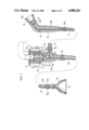
- FIG. 1 is a view in vertical section of a vacuum skin cleaner embodying the present invention
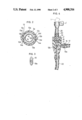
- FIG. 2 is a sectional view taken on lines II--II in FIG. 1;
- FIG. 3 is a plan view showing an example of an applicator cap
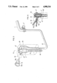
- FIG. 4 is a view in vertical section of another vacuum skin cleaner embodying the present invention.
- FIG. 5 is a perspective view of still another vacuum skin cleaner embodying the present invention.
- FIG. 6 is a sectional view taken on lines VI--VIi in FIG. 5.
- the mounting attachment 2 includes an upper member 4 connectable to the faucet 1. More specifically, the upper member 4 has an enlarged ring portion 4a surrounding the discharge end of the faucet 1, and a cylindrical screw portion 4b extending downward from the ring portion 4a and formed with external threads 7. A plurality (e.g. four) of equiangularly spaced set screws 6 extend radially inward through the ring portion 4a into contaact with the faucet discharge end for fixing the upper member 4 to the faucet 1.
- the screw portion 4b internally supports a sealing ring plate 8 below the faucet discharge end.
- the upper member 4 can be fixed to a faucet discharge end of any cross section by independently advancing the set screws 6 into contact with the faucet discharge end.
- the attachment 2 further includes a lower member 5 screwed to the upper member 4. More particularly, the lower member 5 has a cylindrical screw portion 5a which is formed with internal threads 9 for screw engagement with the screw portion 4b of the upper member 4 and a cylindrical connector portion 5c which is smaller in diameter than the screw portion 5a and extends downward for connection to the negative pressure generator 3.
- the connector portion 5c has, as an integral upward extension thereof, a seal pressing portion 5b which is smaller in diameter than the cylindrical screw portion 4b of the upper member 4.
- the seal pressing portion 5b presses the sealing ring plate 8 against the discharge end of the faucet 1 to provide water-tightness for the attachment 2 itself and for the connection between the faucet 1 and the attachment 2.
- the connector portion 5c is formed with an integral annular projection 10 and a annular groove 11a below the annular projection 10 for receiving an annular seal ring 11.
- the negative pressure generator 3 internally defines a water passage 12 and has an upper cylindrical fitting portion 3a which is releasably mounted to the connector portion 5c of the lower attachment member 5 by means of a lock mechanism 13.
- the lock mechanism 13 comprises a pair of semicircular stopper segments 14 which together form a substantially annular body and are urged toward each other by a pair of springs 13a.
- Each stopper segment 14 has end faces 14a which are opposed to and spaced from the corresponding end faces 14a of the other stopper segment 14 to define a pair of V-shaped gaps.
- Both stopper segments 14 respectively have upper inner circumferential edges 14b which are chamfered to form, in combination, a substantially conical surface.
- the lock mechanism 13 further includes a pair of release buttons 13b which radially extend through the cylindrical fitting portion 3a of the negative pressure generator 3 at a pair of diametrically opposite positions thereof.
- Each button 13b has a wedge head 13c which fits into a corresponding V-shaped gap between the two stopper segments 14.
- the stopper segments 14 are forcibly moved away from each other against the urging force of the springs 13a due to wedging effect between the wedge heads 13c of the respective buttons 13b and the gap forming end faces 14a of the stopper segments 14.
- the stopper segments 14 are automatically displaced toward each other by the restoring force of the springs 13a with resultant retraction of the buttons 13b.
- the retracting movement of each button 13b is restrained by a pin 13d which fits in a radial slot 13e formed in the button 13 b.
- the upper cylindrical portion 3a of the generator 3 is forcibly fitted from below onto the connector portion 5c of the attachment lower member 5.
- the chamfered edges 14b of the stopper segments 14 function to move the segments 14 away from each other against the biasing force of the springs 13a, thereby permitting the segments 14 to ride over and engage with the annular projection 10.
- the seal ring 11 comes into sealing contact with the inner circumferential surface of the upper cylindrical portion 3a to provide water-tightness between the attachment 2 and the negative pressure generator 3.
- the release buttons 13b are pushed to move the stopper segments 14 away from each other, and the generator 3 is pulled downward.
- the water passage 12 formed within the negative pressure generator 3 is provided in the form of a well known venturi, the diameter of which increases progressively in opposite directions from its smallest diameter portion or throat 12a.
- the venturi passage 12 is formed at the smallest diameter portion 12 with an annular slit 12b which communicates with a laterally extending suction nose 15 having an inlet connection end 15a.
- the venturi passage 12 is provided at its inlet end with a flow rectifying member 16 which has a plurality (only one shown) of inclined through-bores 16a.
- the rectifying member 16 imparts a whirling motion to the flowing water to maximize vacuum production at the smallest diameter portion 12a.
- the rectifying member 16 may be modified to have a plurality of screw blades (not shown) instead of the inclined through-bores 16a.
- the inlet end 15a of the suction nose 15 is connected to an outlet end 18a of a grip member 18 by a flexible hose 17.
- the grip member 18 has an air passage 18b extending through it and is formed at its inlet end with a tapered mounting hole 20.
- the grip member 18 is further provided with a vacuum relief port 21 which communicates with an intermediate portion of the air passage 18b.
- the grip member 18 has such a shape as to provide ready gripping and is used to exchangeably mount an applicator cap 19 having an opening mouth 19a for contact with the human skin. More specifically, the cap 19 has a tapered projection 19b which is fitted into the tapered mounting hole 20 of the grip member 18.
- the opening mouth 19a of the cap 19 is oval for facilitated application to portions of the human skin around the nose for example.
- the cap 19 may be replaced by another which is differently dimensioned and shaped depending on a particular portion or portions of the human skin to which it is applied. It should be noted in this connection that a suction force per unit area does not vary despite a change in the overall area of the cap mouth 19a.
- the negative pressure generator 3 has a water discharge end 3b which is connected via a flexible hose 22 to a projecting base portion 23a of a washing attachment 23 which, according to the example illustrated in FIG. 1, is in the form of a cone.
- the conical washing attachment 23 defines a water outlet opening 24. It should be noted that the washing attachment 23 is connected to a discharge end 22a of the hose 22 only at the time of an washing operation but not at the time of suction cleaning.
- the faucet 1 is turned on to supply tap water which flows through the flow rectifying member 16 and then through the venturi passage 12 to ultimately discharge through the hose 22 with the washing attachment 23 detached.
- the water flows at a maximum speed to develop a maximum dynamic pressure while providing a minimum static pressure according to the Bernoulli law. Since the static pressure at the discharge end 22a of the hose 22 is equal to an atmospheric pressure (zero gauge pressure), the static pressure at the venturi throat 12a becomes negative.
- a user grasps the grip member 19 with the opening mouth 19a of the applicator cap 19 pressed against her (or his) intended facial spot and then closes the vacuum relief port 21 by a finger tip.
- the negative pressure at the venturi throat 12a is also applied to the particular facial spot enclosed by the cap opening mouth 19a to conduct desired suction cleaning of the spot.
- Such suction cleaning may be effected over a wide range by moving the applicator cap 19 from one part to another part on the user's face. Further, it is also possible to clean the entire face by selectively using various applicator caps.
- the negative pressure applied to the user's face may be steplessly adjusted by varying the flow rate of the tap water passing through the negative pressure generator 3 or by partially opening the vacuum relief port 21 to different degrees.
- the vacuum relief port 21 may be fully opened to interrupt the suction cleaning operation.
- the skin cleaner of the present invention For practical purpose, it is recommended to use the skin cleaner of the present invention at the time of or immediately after taking a bath. This is because the skin pores are fully open due to heat to allow discharge. Suction cleaning of various eastes (metabolic wastes, cosmetic residues, dust, etc.) which have accumulated within the pores can be accomplished very easily at this time.
- the wastes collected by the applicator cap 19 may be washed away by directing toward the cap 19 the water discharged through the hose 22.
- the washing attachment 23 which has a water passage 23b of reduced cross section, may be connected to the hose 22 to provide a more vigorous jet of water adapted for washing. It should be noted in this connection that a suitable amount of air is introduced through the suction nose 15 into the water discharged through the washing attachment 23 during such washing, and the introduced air forms minute bubbles which ultimately break with resultant production of ultrasonic waves to enhance washing effect.
- the washing attachment 23 may be pressed against the user's face after the above described suction cleaning to conduct washing thereof with comfortable massaging effect which results in accelerated blood circulation and metabolism.
- the conical washing attachment 23 also has an advantage of preventing water splash during such face washing.
- FIG. 4 illustrates a second embodiment of the present invention in which a negative pressure generator 3' is connected to a tap water faucet 1 by means of a vertically extending flexible hose 25. More specifically, the generator 3' has an upper closure member 3c integrally formed with an upward connector projection 3d which is connected to the lower end of the hose 25, whereas the upper end of the hose 25 is connected to the discharge end of the faucet 1 by means of an expandable clamp member 2'. Otherwise, the second embodiment is substantially identical in function and configuration to the first embodiment illustrated in FIG. 1.
- a negative pressure generator 3" is accommodated in a casing 26 which serves as a grip member.
- the generator 3" has a water inlet connector 30 which is connected to one end of a relatively long flexible hose 27.
- the other end of the hose 27 is connected to the discharge end of a faucet 1 by means of an expandable clamp member 2".
- the negative pressure generator 3" internally has a water passage 12" which is designed to produce a negative pressure at a minimum cross-sectional portion 12a".
- the portion 12a" communicates with a suction nose 15" extending forward to a foremost wall 29 of the casing 26 for directly receiving a tapered projection 19b of an applicator cap 19.
- the portion 12a" further communicates with a rearwardly extending vacuum relief port 21" which is closable by a finger.
- the lower end of the negative pressure generator 3" or the water passage 12" is connected to a flexible hose 28 which in turn may be connected to a washing attachment (not shown) which is similar to the one illustrated in FIG. 1.
- the vacuum skin cleaner according to the present invention requires no electric parts (motors, etc.), so that it can be operated very safely and washed clean with water after operation. Further, need for water supply makes the skin cleaner of the present invention particularly advantageous for use in a bath room (during or after taking a bath) where vacuum skin cleaning is considered most effective. Still further, the simplicity in construction of the skin cleaner reduces the possibility of malfunction and ensures a long service.
- the releasable lock mechanism 13 may be provided in the form of spring-biased balls or like elements which engage with and disengage from the annular projection 10 of the attachment lower member 5b in response to push and pull on the negative pressure generator 3, consequently obviating the buttons 13b.
- the water discharge hose 22 (or 28) and the washing attachment 23 may be obviated.
Abstract
Description
Claims (15)
Applications Claiming Priority (2)
| Application Number | Priority Date | Filing Date | Title |
|---|---|---|---|
| JP61247850A JPS63102758A (en) | 1986-10-18 | 1986-10-18 | Suction cleaner for skin |
| JP61-247850 | 1986-10-18 |
Publications (1)
| Publication Number | Publication Date |
|---|---|
| US4900316A true US4900316A (en) | 1990-02-13 |
Family
ID=17169585
Family Applications (1)
| Application Number | Title | Priority Date | Filing Date |
|---|---|---|---|
| US07/109,831 Expired - Lifetime US4900316A (en) | 1986-10-18 | 1987-10-16 | Vacuum skin cleaner |
Country Status (10)
| Country | Link |
|---|---|
| US (1) | US4900316A (en) |
| EP (1) | EP0264851B1 (en) |
| JP (1) | JPS63102758A (en) |
| KR (1) | KR900001073B1 (en) |
| AT (1) | ATE104137T1 (en) |
| AU (1) | AU603388B2 (en) |
| CA (1) | CA1300826C (en) |
| DE (1) | DE3789598T2 (en) |
| ES (1) | ES2050658T3 (en) |
| HK (1) | HK96494A (en) |
Cited By (40)
| Publication number | Priority date | Publication date | Assignee | Title |
|---|---|---|---|---|
| DE4029326C1 (en) * | 1990-09-15 | 1992-03-05 | Viktor Dipl.-Ing. 5900 Siegen De Schatz | |
| US6019749A (en) * | 1998-04-01 | 2000-02-01 | Squeezease, Llc | Apparatus and method for removing material from skin pores |
| USD421128S (en) * | 1999-06-10 | 2000-02-22 | Squeezease, Llc | Skin pore cleaner |
| US6083003A (en) * | 1998-10-23 | 2000-07-04 | Kwasnik; Robert J. | Electromagnetically actuated valve for hydraulic motor vehicle brake systems |
| US6110159A (en) * | 1997-07-29 | 2000-08-29 | Niles Parts Co., Ltd. | Device for disposing excrement |
| US6139554A (en) * | 1999-06-10 | 2000-10-31 | Karkar; Maurice N. | Multipurpose tissue resurfacing handpiece |
| US6162232A (en) * | 1999-03-18 | 2000-12-19 | Shadduck; John H. | Instruments and techniques for high-velocity fluid abrasion of epidermal layers with skin cooling |
| GB2351232A (en) * | 1999-06-25 | 2000-12-27 | Isaac Noel Moody | Suction device for skin care |
| US6299620B1 (en) | 1999-03-18 | 2001-10-09 | Aq Technologies, Inc. | Instruments and techniques for inducing neocollagenesis in skin treatments |
| US6387103B2 (en) * | 1999-12-30 | 2002-05-14 | Aq Technologies, Inc. | Instruments and techniques for inducing neocollagenesis in skin treatments |
| WO2002070040A1 (en) * | 2001-03-05 | 2002-09-12 | Klaus Hoyer | Skin cleaning apparatus for the removal of puss or tallow by suction |
| US6589218B2 (en) * | 2001-01-23 | 2003-07-08 | Teddy Garcia | Suction device for removing material from skin pores |
| US20030212415A1 (en) * | 2001-11-21 | 2003-11-13 | Karasiuk Kenneth B. | Skin treatment system and method of use |
| US20040143274A1 (en) * | 1999-08-26 | 2004-07-22 | Shadduck John H. | Instruments and techniques for controlled removal of epidermal layers |
| US20060253125A1 (en) * | 2005-03-07 | 2006-11-09 | Ignon Roger G | Microdermabrasion method and apparatus |
| US20070156124A1 (en) * | 2005-12-30 | 2007-07-05 | Roger Ignon | Apparatus and methods for treating the skin |
| US20090052996A1 (en) * | 2007-08-21 | 2009-02-26 | Sykora Douglas R | Concrete Rebound Shield and Method of Use |
| US20090177171A1 (en) * | 2008-01-04 | 2009-07-09 | Edge Systems Corporation | Apparatus and method for treating the skin |
| US20090192442A1 (en) * | 2008-01-29 | 2009-07-30 | Edge Systems Corporation | Apparatus and method for treating the skin |
| US20090222023A1 (en) * | 2008-02-29 | 2009-09-03 | Emed, Inc. | Microdermabrasion Treatment Heads |
| US20100137781A1 (en) * | 2006-03-17 | 2010-06-03 | Jackey Chiou | Bubble-Type Nose Cleaner |
| US20110082415A1 (en) * | 2008-01-29 | 2011-04-07 | Edge Systems Corporation | Devices, systems and methods for treating the skin using time-release substances |
| US20110237986A1 (en) * | 2008-11-26 | 2011-09-29 | Hld Healthy Life Devices Ltd | Arrangement in connection with massaging apparatus, and massaging apparatus |
| US20140296751A1 (en) * | 2011-11-14 | 2014-10-02 | Diamond Medical Aesthetics Pty Ltd | Apparatus and method of body contouring and skin conditioning |
| US9050133B1 (en) | 2009-12-22 | 2015-06-09 | Envy Medical, Inc. | Skin treatment system with adjustable height wand |
| US9498610B2 (en) | 2014-12-23 | 2016-11-22 | Edge Systems Llc | Devices and methods for treating the skin using a rollerball or a wicking member |
| US9566088B2 (en) | 2006-03-29 | 2017-02-14 | Edge Systems Llc | Devices, systems and methods for treating the skin |
| US20170196759A1 (en) * | 2016-01-07 | 2017-07-13 | Hld Healthy Life Devices Oy | Arrangement in connection with low pressure suction apparatus |
| US9763851B2 (en) | 2013-09-23 | 2017-09-19 | Novoluto Gmbh | Stimulation device |
| US9833261B2 (en) | 2008-08-22 | 2017-12-05 | Envy Medical, Inc. | Microdermabrasion system upgrade kit |
| US9849061B2 (en) | 2015-03-13 | 2017-12-26 | Novoluto Gmbh | Stimulation device having an appendage |
| US10172644B2 (en) | 2006-03-29 | 2019-01-08 | Edge Systems Llc | Devices, systems and methods for treating the skin |
| US10179229B2 (en) | 2014-12-23 | 2019-01-15 | Edge Systems Llc | Devices and methods for treating the skin using a porous member |
| US10238812B2 (en) | 2013-03-15 | 2019-03-26 | Edge Systems Llc | Skin treatment systems and methods using needles |
| US10485983B1 (en) | 2008-08-22 | 2019-11-26 | Envy Medical, Inc. | Microdermabrasion system with combination skin therapies |
| WO2020047522A1 (en) * | 2018-08-31 | 2020-03-05 | Coutu Philip | Multi-functional shower head attachment device with suction and pressure capability |
| US10993743B2 (en) | 2013-03-15 | 2021-05-04 | Edge Systems Llc | Devices, systems and methods for treating the skin |
| US11241357B2 (en) | 2015-07-08 | 2022-02-08 | Edge Systems Llc | Devices, systems and methods for promoting hair growth |
| CN116870279A (en) * | 2023-09-06 | 2023-10-13 | 德州雷奥巴赫医疗器械有限公司 | Intelligent debridement instrument |
| USD1016615S1 (en) | 2021-09-10 | 2024-03-05 | Hydrafacial Llc | Container for a skin treatment device |
Families Citing this family (7)
| Publication number | Priority date | Publication date | Assignee | Title |
|---|---|---|---|---|
| JPH03158155A (en) * | 1989-11-16 | 1991-07-08 | Azu Internatl:Kk | Breast well-fleshing device |
| JPH03297466A (en) * | 1990-04-17 | 1991-12-27 | Azu Internatl:Kk | Integrated sanitary, healthy and beauty system used in bath room |
| DE4123531C2 (en) * | 1991-07-16 | 1995-06-29 | Jahoda Frantisek | Exercise machine for training dynamic explosive muscle strength |
| JP2739090B2 (en) * | 1993-04-15 | 1998-04-08 | 株式会社ビバリーコーポレーション | Beauty instrument |
| DE19900642C2 (en) * | 1998-01-14 | 2003-02-20 | Matsushita Electric Works Ltd | Facial care apparatus |
| KR100930042B1 (en) * | 2008-03-13 | 2009-12-08 | 박찬형 | Massage cup and massage device using same |
| JP5963659B2 (en) * | 2012-12-03 | 2016-08-03 | 新興プランテック株式会社 | Bolt / nut attaching / detaching support jig |
Citations (10)
| Publication number | Priority date | Publication date | Assignee | Title |
|---|---|---|---|---|
| US733881A (en) * | 1903-04-08 | 1903-07-14 | Isral Goldstein | Faucet attachment. |
| US948005A (en) * | 1909-01-16 | 1910-02-01 | Andrew Russell Campbell | Massager. |
| US1080420A (en) * | 1911-01-17 | 1913-12-02 | Water Power Vacuum Cleaner Co | Vacuum cleaning apparatus. |
| US1196344A (en) * | 1913-02-19 | 1916-08-29 | Luis De Florez | Massage apparatus. |
| CH137886A (en) * | 1927-12-20 | 1930-01-31 | Aghnides Elie | Apparatus for determining the flow of blood and activating skin respiration. |
| FR836360A (en) * | 1938-04-08 | 1939-01-17 | Method and apparatus for the treatment of the scalp or other applications | |
| US3227380A (en) * | 1963-02-04 | 1966-01-04 | James T Pinkston | Quick connector spigot coupling for spray nozzle and aerator attachments |
| US3808631A (en) * | 1969-11-13 | 1974-05-07 | Mitsubishi Heavy Ind Ltd | Device for removing a sludge from a surface |
| US3964484A (en) * | 1975-03-03 | 1976-06-22 | Sorenson Research Co., Inc. | Antiocoagulant metering device and method |
| US4540406A (en) * | 1983-05-02 | 1985-09-10 | Thoratec Laboratories Corporation | Anticoagulant delivery system for use with an auto-transfusion system |
Family Cites Families (8)
| Publication number | Priority date | Publication date | Assignee | Title |
|---|---|---|---|---|
| GB274107A (en) * | 1926-07-09 | 1928-07-19 | Lucien Joseph Vivier | Injector and like apparatus for producing variations of pressure in fluids |
| CH286671A (en) * | 1950-09-09 | 1952-10-31 | Freitag Fritz | Massager. |
| JPS4825972U (en) * | 1971-08-03 | 1973-03-28 | ||
| JPS5111617Y2 (en) * | 1971-08-27 | 1976-03-29 | ||
| JPS595800B2 (en) * | 1977-12-20 | 1984-02-07 | 三菱重工業株式会社 | Centripetal fan |
| JPS5632938A (en) * | 1979-08-27 | 1981-04-02 | Kazuo Ariyoshi | Giant fish bank |
| JPS595800U (en) * | 1982-07-02 | 1984-01-14 | ヤマト科学株式会社 | Aspirator |
| JPS60116919U (en) * | 1984-01-13 | 1985-08-07 | 松下電工株式会社 | facial beauty device |
-
1986
- 1986-10-18 JP JP61247850A patent/JPS63102758A/en active Granted
-
1987
- 1987-10-16 ES ES87115164T patent/ES2050658T3/en not_active Expired - Lifetime
- 1987-10-16 US US07/109,831 patent/US4900316A/en not_active Expired - Lifetime
- 1987-10-16 DE DE3789598T patent/DE3789598T2/en not_active Expired - Fee Related
- 1987-10-16 AT AT87115164T patent/ATE104137T1/en not_active IP Right Cessation
- 1987-10-16 EP EP87115164A patent/EP0264851B1/en not_active Expired - Lifetime
- 1987-10-16 CA CA000549498A patent/CA1300826C/en not_active Expired - Lifetime
- 1987-10-17 KR KR1019870011589A patent/KR900001073B1/en not_active IP Right Cessation
- 1987-10-19 AU AU79919/87A patent/AU603388B2/en not_active Ceased
-
1994
- 1994-09-08 HK HK96494A patent/HK96494A/en unknown
Patent Citations (10)
| Publication number | Priority date | Publication date | Assignee | Title |
|---|---|---|---|---|
| US733881A (en) * | 1903-04-08 | 1903-07-14 | Isral Goldstein | Faucet attachment. |
| US948005A (en) * | 1909-01-16 | 1910-02-01 | Andrew Russell Campbell | Massager. |
| US1080420A (en) * | 1911-01-17 | 1913-12-02 | Water Power Vacuum Cleaner Co | Vacuum cleaning apparatus. |
| US1196344A (en) * | 1913-02-19 | 1916-08-29 | Luis De Florez | Massage apparatus. |
| CH137886A (en) * | 1927-12-20 | 1930-01-31 | Aghnides Elie | Apparatus for determining the flow of blood and activating skin respiration. |
| FR836360A (en) * | 1938-04-08 | 1939-01-17 | Method and apparatus for the treatment of the scalp or other applications | |
| US3227380A (en) * | 1963-02-04 | 1966-01-04 | James T Pinkston | Quick connector spigot coupling for spray nozzle and aerator attachments |
| US3808631A (en) * | 1969-11-13 | 1974-05-07 | Mitsubishi Heavy Ind Ltd | Device for removing a sludge from a surface |
| US3964484A (en) * | 1975-03-03 | 1976-06-22 | Sorenson Research Co., Inc. | Antiocoagulant metering device and method |
| US4540406A (en) * | 1983-05-02 | 1985-09-10 | Thoratec Laboratories Corporation | Anticoagulant delivery system for use with an auto-transfusion system |
Cited By (98)
| Publication number | Priority date | Publication date | Assignee | Title |
|---|---|---|---|---|
| DE4029326C1 (en) * | 1990-09-15 | 1992-03-05 | Viktor Dipl.-Ing. 5900 Siegen De Schatz | |
| US5295982A (en) * | 1990-09-15 | 1994-03-22 | Viktor Schatz | Suction device for cleaning skin |
| US6110159A (en) * | 1997-07-29 | 2000-08-29 | Niles Parts Co., Ltd. | Device for disposing excrement |
| US6019749A (en) * | 1998-04-01 | 2000-02-01 | Squeezease, Llc | Apparatus and method for removing material from skin pores |
| US6083003A (en) * | 1998-10-23 | 2000-07-04 | Kwasnik; Robert J. | Electromagnetically actuated valve for hydraulic motor vehicle brake systems |
| US6162232A (en) * | 1999-03-18 | 2000-12-19 | Shadduck; John H. | Instruments and techniques for high-velocity fluid abrasion of epidermal layers with skin cooling |
| US6299620B1 (en) | 1999-03-18 | 2001-10-09 | Aq Technologies, Inc. | Instruments and techniques for inducing neocollagenesis in skin treatments |
| USD421128S (en) * | 1999-06-10 | 2000-02-22 | Squeezease, Llc | Skin pore cleaner |
| US6139554A (en) * | 1999-06-10 | 2000-10-31 | Karkar; Maurice N. | Multipurpose tissue resurfacing handpiece |
| GB2351232A (en) * | 1999-06-25 | 2000-12-27 | Isaac Noel Moody | Suction device for skin care |
| US20040143274A1 (en) * | 1999-08-26 | 2004-07-22 | Shadduck John H. | Instruments and techniques for controlled removal of epidermal layers |
| US20070208353A1 (en) * | 1999-08-26 | 2007-09-06 | Shadduck John H | Instruments and techniques for controlled removal of epidermal layers |
| US7789886B2 (en) | 1999-08-26 | 2010-09-07 | Axia Medsciences, Llc | Instruments and techniques for controlled removal of epidermal layers |
| US8066716B2 (en) | 1999-08-26 | 2011-11-29 | Axia Medsciences, Llc | Instruments and techniques for controlled removal of epidermal layers |
| US8337513B2 (en) | 1999-08-26 | 2012-12-25 | Axia Medsciences, Llc | Instruments and techniques for controlled removal of epidermal layers |
| US20060200172A1 (en) * | 1999-08-26 | 2006-09-07 | Shadduck John H | Instruments and techniques for controlled removal of epidermal layers |
| US20060200173A1 (en) * | 1999-08-26 | 2006-09-07 | Shadduck John H | Instruments and techniques for controlled removal of epidermal layers |
| US7678120B2 (en) | 1999-08-26 | 2010-03-16 | Axia Medsciences, Llc | Instruments and techniques for controlled removal of epidermal layers |
| US9775646B2 (en) | 1999-08-26 | 2017-10-03 | Axia Medsciences, Llc | Devices and systems for treating the skin using vacuum |
| US9468464B2 (en) | 1999-08-26 | 2016-10-18 | Axia Medsciences, Llc | Methods for treating the skin using vacuum |
| US6387103B2 (en) * | 1999-12-30 | 2002-05-14 | Aq Technologies, Inc. | Instruments and techniques for inducing neocollagenesis in skin treatments |
| US6589218B2 (en) * | 2001-01-23 | 2003-07-08 | Teddy Garcia | Suction device for removing material from skin pores |
| WO2002070040A1 (en) * | 2001-03-05 | 2002-09-12 | Klaus Hoyer | Skin cleaning apparatus for the removal of puss or tallow by suction |
| US9517085B2 (en) | 2001-11-21 | 2016-12-13 | Envy Medical, Inc. | Skin treatment system and method of use |
| US8721662B2 (en) | 2001-11-21 | 2014-05-13 | Envy Medical, Inc. | Skin treatment system and method of use |
| US7658742B2 (en) | 2001-11-21 | 2010-02-09 | Envy Medical, Inc. | Skin treatment system and method of use |
| US7951156B2 (en) | 2001-11-21 | 2011-05-31 | Envy Medical, Inc. | Skin treatment system and method of use |
| US20030212415A1 (en) * | 2001-11-21 | 2003-11-13 | Karasiuk Kenneth B. | Skin treatment system and method of use |
| US20060253125A1 (en) * | 2005-03-07 | 2006-11-09 | Ignon Roger G | Microdermabrasion method and apparatus |
| US9550052B2 (en) | 2005-12-30 | 2017-01-24 | Edge Systems Llc | Console system for the treatment of skin |
| US10357641B2 (en) | 2005-12-30 | 2019-07-23 | Edge Systems Llc | Tips for skin treatment device |
| US11865287B2 (en) | 2005-12-30 | 2024-01-09 | Hydrafacial Llc | Devices and methods for treating skin |
| US8048089B2 (en) | 2005-12-30 | 2011-11-01 | Edge Systems Corporation | Apparatus and methods for treating the skin |
| US9662482B2 (en) | 2005-12-30 | 2017-05-30 | Edge Systems Llc | Methods and systems for extraction of materials from skin |
| US10357642B2 (en) | 2005-12-30 | 2019-07-23 | Edge Systems Llc | Removable tips for use with skin treatment systems |
| US9814868B2 (en) | 2005-12-30 | 2017-11-14 | Edge Systems Llc | Tip with embedded materials for skin treatment |
| US20070156124A1 (en) * | 2005-12-30 | 2007-07-05 | Roger Ignon | Apparatus and methods for treating the skin |
| US9474886B2 (en) | 2005-12-30 | 2016-10-25 | Edge Systems Llc | Removable tips for skin treatment systems |
| US11612726B2 (en) | 2005-12-30 | 2023-03-28 | Hydrafacial Llc | Devices and methods for treating skin |
| US11547840B2 (en) | 2005-12-30 | 2023-01-10 | Hydrafacial Llc | Devices and methods for treating skin |
| US11446477B2 (en) | 2005-12-30 | 2022-09-20 | Hydrafacial Llc | Devices and methods for treating skin |
| US8486050B2 (en) * | 2006-03-17 | 2013-07-16 | Jackey Chiou | Bubble-type nose cleaner |
| US20100137781A1 (en) * | 2006-03-17 | 2010-06-03 | Jackey Chiou | Bubble-Type Nose Cleaner |
| US10172644B2 (en) | 2006-03-29 | 2019-01-08 | Edge Systems Llc | Devices, systems and methods for treating the skin |
| US10251675B2 (en) | 2006-03-29 | 2019-04-09 | Edge Systems Llc | Devices, systems and methods for treating the skin |
| US11717326B2 (en) | 2006-03-29 | 2023-08-08 | Hydrafacial Llc | Devices, systems and methods for treating the skin |
| US9566088B2 (en) | 2006-03-29 | 2017-02-14 | Edge Systems Llc | Devices, systems and methods for treating the skin |
| US20090052996A1 (en) * | 2007-08-21 | 2009-02-26 | Sykora Douglas R | Concrete Rebound Shield and Method of Use |
| US7736098B2 (en) * | 2007-08-21 | 2010-06-15 | Sykora Douglas R | Concrete rebound shield and method of use |
| US20090177171A1 (en) * | 2008-01-04 | 2009-07-09 | Edge Systems Corporation | Apparatus and method for treating the skin |
| US11883621B2 (en) | 2008-01-04 | 2024-01-30 | Hydrafacial Llc | Devices and methods for skin treatment |
| US9486615B2 (en) | 2008-01-04 | 2016-11-08 | Edge Systems Llc | Microdermabrasion apparatus and method |
| US8343116B2 (en) | 2008-01-04 | 2013-01-01 | Edge Systems Corporation | Apparatus and method for treating the skin |
| US10556096B2 (en) | 2008-01-04 | 2020-02-11 | Edge Systems Llc | Devices and methods for skin treatment |
| US9642997B2 (en) | 2008-01-29 | 2017-05-09 | Edge Systems Llc | Devices for treating skin using treatment materials located along a tip |
| US11020577B2 (en) | 2008-01-29 | 2021-06-01 | Edge Systems Llc | Devices and systems for treating skin surfaces |
| US10556097B2 (en) | 2008-01-29 | 2020-02-11 | Edge Systems Llc | Devices for treating skin using treatment materials located along a tip |
| US8814836B2 (en) | 2008-01-29 | 2014-08-26 | Edge Systems Llc | Devices, systems and methods for treating the skin using time-release substances |
| US20090192442A1 (en) * | 2008-01-29 | 2009-07-30 | Edge Systems Corporation | Apparatus and method for treating the skin |
| US20110082415A1 (en) * | 2008-01-29 | 2011-04-07 | Edge Systems Corporation | Devices, systems and methods for treating the skin using time-release substances |
| US9056193B2 (en) | 2008-01-29 | 2015-06-16 | Edge Systems Llc | Apparatus and method for treating the skin |
| US8236008B2 (en) | 2008-02-29 | 2012-08-07 | Envy Medical, Inc. | Microdermabrasion treatment heads |
| US20090222023A1 (en) * | 2008-02-29 | 2009-09-03 | Emed, Inc. | Microdermabrasion Treatment Heads |
| US9655432B2 (en) | 2008-02-29 | 2017-05-23 | Envy Medical, Inc. | Microdermabrasion treatment heads |
| US10898227B2 (en) | 2008-02-29 | 2021-01-26 | Envy Medical, Inc. | Microdermabrasion treatment heads |
| US9833261B2 (en) | 2008-08-22 | 2017-12-05 | Envy Medical, Inc. | Microdermabrasion system upgrade kit |
| US10485983B1 (en) | 2008-08-22 | 2019-11-26 | Envy Medical, Inc. | Microdermabrasion system with combination skin therapies |
| US20110237986A1 (en) * | 2008-11-26 | 2011-09-29 | Hld Healthy Life Devices Ltd | Arrangement in connection with massaging apparatus, and massaging apparatus |
| US9050133B1 (en) | 2009-12-22 | 2015-06-09 | Envy Medical, Inc. | Skin treatment system with adjustable height wand |
| US9918727B1 (en) | 2009-12-22 | 2018-03-20 | Envy Medical, Inc. | Skin treatment system with adjustable height wand |
| US10492807B1 (en) | 2009-12-22 | 2019-12-03 | Envy Medical, Inc. | Skin treatment system with adjustable height wand |
| US20140296751A1 (en) * | 2011-11-14 | 2014-10-02 | Diamond Medical Aesthetics Pty Ltd | Apparatus and method of body contouring and skin conditioning |
| US10238812B2 (en) | 2013-03-15 | 2019-03-26 | Edge Systems Llc | Skin treatment systems and methods using needles |
| US11202657B2 (en) | 2013-03-15 | 2021-12-21 | Edge Systems Llc | Devices, systems and methods for treating the skin |
| US11903615B2 (en) | 2013-03-15 | 2024-02-20 | Hydrafacial Llc | Devices, systems and methods for treating the skin |
| US10993743B2 (en) | 2013-03-15 | 2021-05-04 | Edge Systems Llc | Devices, systems and methods for treating the skin |
| US11517350B2 (en) | 2013-03-15 | 2022-12-06 | Hydrafacial Llc | Devices, systems and methods for treating the skin |
| US11213321B2 (en) | 2013-03-15 | 2022-01-04 | Edge Systems Llc | Devices, systems and methods for treating the skin |
| US11103418B2 (en) | 2013-09-23 | 2021-08-31 | Novoluto Gmbh | Stimulation device |
| US11090220B2 (en) | 2013-09-23 | 2021-08-17 | Novoluto Gbhh | Stimulation device |
| US10857063B2 (en) | 2013-09-23 | 2020-12-08 | Novoluto Gmbh | Stimulation device |
| US9763851B2 (en) | 2013-09-23 | 2017-09-19 | Novoluto Gmbh | Stimulation device |
| US11744999B2 (en) | 2014-12-23 | 2023-09-05 | Hydra Facial LLC | Devices and methods for treating the skin |
| US11925780B2 (en) | 2014-12-23 | 2024-03-12 | Hydrafacial Llc | Devices and methods for treating the skin |
| US11224728B2 (en) | 2014-12-23 | 2022-01-18 | Edge Systems Llc | Devices and methods for treating the skin using a porous member |
| US9498610B2 (en) | 2014-12-23 | 2016-11-22 | Edge Systems Llc | Devices and methods for treating the skin using a rollerball or a wicking member |
| US10035007B2 (en) | 2014-12-23 | 2018-07-31 | Edge Systems Llc | Devices and methods for treating the skin |
| US10179229B2 (en) | 2014-12-23 | 2019-01-15 | Edge Systems Llc | Devices and methods for treating the skin using a porous member |
| US11806495B2 (en) | 2014-12-23 | 2023-11-07 | Hydrafacial Llc | Devices and methods for treating the skin |
| US9849061B2 (en) | 2015-03-13 | 2017-12-26 | Novoluto Gmbh | Stimulation device having an appendage |
| US9937097B2 (en) | 2015-03-13 | 2018-04-10 | Novoluto Gmbh | Stimulation device having an appendage |
| US11241357B2 (en) | 2015-07-08 | 2022-02-08 | Edge Systems Llc | Devices, systems and methods for promoting hair growth |
| US20170196759A1 (en) * | 2016-01-07 | 2017-07-13 | Hld Healthy Life Devices Oy | Arrangement in connection with low pressure suction apparatus |
| WO2020047522A1 (en) * | 2018-08-31 | 2020-03-05 | Coutu Philip | Multi-functional shower head attachment device with suction and pressure capability |
| KR20210068026A (en) * | 2018-08-31 | 2021-06-08 | 필립 쿠투 | Multifunctional showerhead attachment with suction and pressure function |
| USD1016615S1 (en) | 2021-09-10 | 2024-03-05 | Hydrafacial Llc | Container for a skin treatment device |
| CN116870279A (en) * | 2023-09-06 | 2023-10-13 | 德州雷奥巴赫医疗器械有限公司 | Intelligent debridement instrument |
| CN116870279B (en) * | 2023-09-06 | 2023-11-14 | 德州雷奥巴赫医疗器械有限公司 | Intelligent debridement instrument |
Also Published As
| Publication number | Publication date |
|---|---|
| KR880004793A (en) | 1988-06-27 |
| ATE104137T1 (en) | 1994-04-15 |
| EP0264851A3 (en) | 1989-08-23 |
| AU7991987A (en) | 1988-04-21 |
| JPS63102758A (en) | 1988-05-07 |
| CA1300826C (en) | 1992-05-19 |
| KR900001073B1 (en) | 1990-02-26 |
| HK96494A (en) | 1994-09-16 |
| DE3789598D1 (en) | 1994-05-19 |
| DE3789598T2 (en) | 1994-07-21 |
| ES2050658T3 (en) | 1994-06-01 |
| EP0264851B1 (en) | 1994-04-13 |
| EP0264851A2 (en) | 1988-04-27 |
| AU603388B2 (en) | 1990-11-15 |
| JPH0379020B2 (en) | 1991-12-17 |
Similar Documents
| Publication | Publication Date | Title |
|---|---|---|
| US4900316A (en) | Vacuum skin cleaner | |
| WO2005074856A1 (en) | Massage nozzle and massage device | |
| KR100536779B1 (en) | Skin management device for massage and sebum removal | |
| US2812519A (en) | Hair washing apparatus | |
| JP2004136085A (en) | Massage nozzle and massage system | |
| JP4092648B2 (en) | Massage nozzle and massage system | |
| JP4133893B2 (en) | Massage nozzle and massage device | |
| JP4133892B2 (en) | Massage nozzle and massage device | |
| KR20090101071A (en) | Multi function shower device | |
| CN209809229U (en) | Skin cleaning device and beauty instrument with same | |
| JP4158103B2 (en) | Massage nozzle and massage system | |
| CN215878383U (en) | Atomizing pouring nozzle for medical beauty | |
| JP3098252U (en) | Eye nose washing device | |
| JPH0724670B2 (en) | Suction handle for suction facial treatment | |
| CN212089359U (en) | Face massage cleaning device capable of wiping moisturizing cream | |
| CN219231170U (en) | Liquid medicine applicator for treating alopecia | |
| KR200220356Y1 (en) | Auto Shawer | |
| CN215194895U (en) | Otolaryngology clinical medicine device that spouts with adjustable | |
| JPH04364847A (en) | Suction type cleaner for skin application | |
| CN213429800U (en) | Height-adjustable's handheld gondola water faucet of massage | |
| JP4395887B2 (en) | Massage head and massage system | |
| JP3161437B2 (en) | Hot water jet nozzle structure of bubble generating bathtub | |
| JP2006034829A (en) | Massage nozzle and massage system | |
| JP3017190U (en) | attachment | |
| JPS6314716Y2 (en) |
Legal Events
| Date | Code | Title | Description |
|---|---|---|---|
| AS | Assignment |
Owner name: AZZ INTERNATIONAL CO., LTD., MIDO URBAN-LIFE NO. 7 Free format text: ASSIGNMENT OF ASSIGNORS INTEREST.;ASSIGNOR:YAMAMOTO, MASUO;REEL/FRAME:004818/0549 Effective date: 19871130 Owner name: AZZ INTERNATIONAL CO., LTD.,JAPAN Free format text: ASSIGNMENT OF ASSIGNORS INTEREST;ASSIGNOR:YAMAMOTO, MASUO;REEL/FRAME:004818/0549 Effective date: 19871130 |
|
| STCF | Information on status: patent grant |
Free format text: PATENTED CASE |
|
| FEPP | Fee payment procedure |
Free format text: PAYOR NUMBER ASSIGNED (ORIGINAL EVENT CODE: ASPN); ENTITY STATUS OF PATENT OWNER: SMALL ENTITY |
|
| FPAY | Fee payment |
Year of fee payment: 4 |
|
| AS | Assignment |
Owner name: NISSHIN ELECTRIC ENGINEERING & WORKS CO., LTD., JA Free format text: ASSIGNMENT OF ASSIGNORS INTEREST;ASSIGNOR:AZZ INTERNATIONAL CO., LTD.;REEL/FRAME:008167/0116 Effective date: 19960924 |
|
| FPAY | Fee payment |
Year of fee payment: 8 |
|
| FPAY | Fee payment |
Year of fee payment: 12 |