US5834082A - Reinforced foam cores and method and apparatus of production - Google Patents
Reinforced foam cores and method and apparatus of production Download PDFInfo
- Publication number
- US5834082A US5834082A US08/775,403 US77540396A US5834082A US 5834082 A US5834082 A US 5834082A US 77540396 A US77540396 A US 77540396A US 5834082 A US5834082 A US 5834082A
- Authority
- US
- United States
- Prior art keywords
- panel
- foam
- core
- webs
- skins
- Prior art date
- Legal status (The legal status is an assumption and is not a legal conclusion. Google has not performed a legal analysis and makes no representation as to the accuracy of the status listed.)
- Expired - Lifetime
Links
- 239000006260 foam Substances 0.000 title claims abstract description 248
- 238000000034 method Methods 0.000 title description 35
- 238000004519 manufacturing process Methods 0.000 title description 8
- 229920005989 resin Polymers 0.000 claims abstract description 85
- 239000011347 resin Substances 0.000 claims abstract description 85
- 239000000463 material Substances 0.000 claims abstract description 48
- 239000000835 fiber Substances 0.000 claims description 54
- 230000003014 reinforcing effect Effects 0.000 claims description 34
- 230000001965 increasing effect Effects 0.000 claims description 11
- 239000006261 foam material Substances 0.000 claims description 8
- 229920003023 plastic Polymers 0.000 claims description 6
- 239000004033 plastic Substances 0.000 claims description 6
- 239000004840 adhesive resin Substances 0.000 claims description 4
- 229920006223 adhesive resin Polymers 0.000 claims description 4
- 230000001154 acute effect Effects 0.000 abstract description 7
- 230000000704 physical effect Effects 0.000 abstract description 2
- 239000011162 core material Substances 0.000 description 227
- 239000002131 composite material Substances 0.000 description 58
- 239000010410 layer Substances 0.000 description 47
- 239000000853 adhesive Substances 0.000 description 33
- 230000001070 adhesive effect Effects 0.000 description 33
- 239000011152 fibreglass Substances 0.000 description 29
- 230000002787 reinforcement Effects 0.000 description 21
- 238000009413 insulation Methods 0.000 description 18
- 230000008569 process Effects 0.000 description 15
- 210000004027 cell Anatomy 0.000 description 13
- 238000005520 cutting process Methods 0.000 description 13
- 239000004744 fabric Substances 0.000 description 11
- 239000004619 high density foam Substances 0.000 description 10
- 239000012779 reinforcing material Substances 0.000 description 10
- 230000004888 barrier function Effects 0.000 description 9
- 239000002984 plastic foam Substances 0.000 description 9
- MCSOAHVAIJXNDN-ZTFGCOKTSA-N ram-322 Chemical compound C1C(=O)CC[C@@]2(O)[C@H]3CC4=CC=C(OC)C(O)=C4[C@]21CCN3C MCSOAHVAIJXNDN-ZTFGCOKTSA-N 0.000 description 9
- 239000004820 Pressure-sensitive adhesive Substances 0.000 description 8
- 230000008901 benefit Effects 0.000 description 6
- 238000010276 construction Methods 0.000 description 6
- 238000005187 foaming Methods 0.000 description 6
- 239000000203 mixture Substances 0.000 description 6
- 238000009826 distribution Methods 0.000 description 5
- 239000004620 low density foam Substances 0.000 description 5
- 238000003825 pressing Methods 0.000 description 5
- 239000000126 substance Substances 0.000 description 5
- 229920001169 thermoplastic Polymers 0.000 description 5
- 239000012815 thermoplastic material Substances 0.000 description 5
- 239000004416 thermosoftening plastic Substances 0.000 description 5
- 239000002657 fibrous material Substances 0.000 description 4
- 239000012530 fluid Substances 0.000 description 4
- 238000005470 impregnation Methods 0.000 description 4
- 239000012528 membrane Substances 0.000 description 4
- 229910052782 aluminium Inorganic materials 0.000 description 3
- XAGFODPZIPBFFR-UHFFFAOYSA-N aluminium Chemical compound [Al] XAGFODPZIPBFFR-UHFFFAOYSA-N 0.000 description 3
- 239000011324 bead Substances 0.000 description 3
- 238000005452 bending Methods 0.000 description 3
- 230000001413 cellular effect Effects 0.000 description 3
- 238000007906 compression Methods 0.000 description 3
- 230000006835 compression Effects 0.000 description 3
- 239000007788 liquid Substances 0.000 description 3
- 238000003754 machining Methods 0.000 description 3
- 230000035515 penetration Effects 0.000 description 3
- 229920000728 polyester Polymers 0.000 description 3
- 229920000582 polyisocyanurate Polymers 0.000 description 3
- 239000011495 polyisocyanurate Substances 0.000 description 3
- -1 polypropylene Polymers 0.000 description 3
- 239000004814 polyurethane Substances 0.000 description 3
- 239000004800 polyvinyl chloride Substances 0.000 description 3
- 239000011148 porous material Substances 0.000 description 3
- 239000012783 reinforcing fiber Substances 0.000 description 3
- 239000002023 wood Substances 0.000 description 3
- 239000004696 Poly ether ether ketone Substances 0.000 description 2
- 239000004743 Polypropylene Substances 0.000 description 2
- 239000004793 Polystyrene Substances 0.000 description 2
- 238000004026 adhesive bonding Methods 0.000 description 2
- 230000000712 assembly Effects 0.000 description 2
- 238000000429 assembly Methods 0.000 description 2
- 150000001875 compounds Chemical class 0.000 description 2
- 238000010924 continuous production Methods 0.000 description 2
- 238000013461 design Methods 0.000 description 2
- 238000009472 formulation Methods 0.000 description 2
- 239000003365 glass fiber Substances 0.000 description 2
- 238000000227 grinding Methods 0.000 description 2
- 239000012943 hotmelt Substances 0.000 description 2
- 238000010030 laminating Methods 0.000 description 2
- 229910052751 metal Inorganic materials 0.000 description 2
- 239000002184 metal Substances 0.000 description 2
- 238000012986 modification Methods 0.000 description 2
- 230000004048 modification Effects 0.000 description 2
- 239000000123 paper Substances 0.000 description 2
- 230000037368 penetrate the skin Effects 0.000 description 2
- 230000000149 penetrating effect Effects 0.000 description 2
- ISWSIDIOOBJBQZ-UHFFFAOYSA-N phenol group Chemical group C1(=CC=CC=C1)O ISWSIDIOOBJBQZ-UHFFFAOYSA-N 0.000 description 2
- 239000002985 plastic film Substances 0.000 description 2
- 229920002530 polyetherether ketone Polymers 0.000 description 2
- 229920001155 polypropylene Polymers 0.000 description 2
- 229920002223 polystyrene Polymers 0.000 description 2
- 229920002635 polyurethane Polymers 0.000 description 2
- 229920000915 polyvinyl chloride Polymers 0.000 description 2
- 238000000926 separation method Methods 0.000 description 2
- 238000009751 slip forming Methods 0.000 description 2
- 125000006850 spacer group Chemical group 0.000 description 2
- 229920005992 thermoplastic resin Polymers 0.000 description 2
- 229920001187 thermosetting polymer Polymers 0.000 description 2
- 238000001721 transfer moulding Methods 0.000 description 2
- XLYOFNOQVPJJNP-UHFFFAOYSA-N water Substances O XLYOFNOQVPJJNP-UHFFFAOYSA-N 0.000 description 2
- 238000003855 Adhesive Lamination Methods 0.000 description 1
- OKTJSMMVPCPJKN-UHFFFAOYSA-N Carbon Chemical compound [C] OKTJSMMVPCPJKN-UHFFFAOYSA-N 0.000 description 1
- 239000004821 Contact adhesive Substances 0.000 description 1
- 239000004593 Epoxy Substances 0.000 description 1
- JOYRKODLDBILNP-UHFFFAOYSA-N Ethyl urethane Chemical compound CCOC(N)=O JOYRKODLDBILNP-UHFFFAOYSA-N 0.000 description 1
- 229920002430 Fibre-reinforced plastic Polymers 0.000 description 1
- 240000007182 Ochroma pyramidale Species 0.000 description 1
- 238000005299 abrasion Methods 0.000 description 1
- 230000009471 action Effects 0.000 description 1
- 239000012790 adhesive layer Substances 0.000 description 1
- 238000013459 approach Methods 0.000 description 1
- 229910052799 carbon Inorganic materials 0.000 description 1
- 230000015556 catabolic process Effects 0.000 description 1
- 210000002421 cell wall Anatomy 0.000 description 1
- 239000004568 cement Substances 0.000 description 1
- 238000000576 coating method Methods 0.000 description 1
- 230000007812 deficiency Effects 0.000 description 1
- 230000002950 deficient Effects 0.000 description 1
- 238000006731 degradation reaction Methods 0.000 description 1
- 230000001419 dependent effect Effects 0.000 description 1
- 230000006866 deterioration Effects 0.000 description 1
- 229910003460 diamond Inorganic materials 0.000 description 1
- 239000010432 diamond Substances 0.000 description 1
- 230000003028 elevating effect Effects 0.000 description 1
- 230000007613 environmental effect Effects 0.000 description 1
- 239000004794 expanded polystyrene Substances 0.000 description 1
- 239000011151 fibre-reinforced plastic Substances 0.000 description 1
- 239000011494 foam glass Substances 0.000 description 1
- 239000011888 foil Substances 0.000 description 1
- 239000011521 glass Substances 0.000 description 1
- 238000001802 infusion Methods 0.000 description 1
- 238000009434 installation Methods 0.000 description 1
- 230000010354 integration Effects 0.000 description 1
- 239000002655 kraft paper Substances 0.000 description 1
- 230000013011 mating Effects 0.000 description 1
- 239000011159 matrix material Substances 0.000 description 1
- 238000013508 migration Methods 0.000 description 1
- 230000005012 migration Effects 0.000 description 1
- 238000000465 moulding Methods 0.000 description 1
- 229920006255 plastic film Polymers 0.000 description 1
- 239000000088 plastic resin Substances 0.000 description 1
- 239000011120 plywood Substances 0.000 description 1
- 229920001225 polyester resin Polymers 0.000 description 1
- 239000004645 polyester resin Substances 0.000 description 1
- 229920005749 polyurethane resin Polymers 0.000 description 1
- 239000000843 powder Substances 0.000 description 1
- 230000002028 premature Effects 0.000 description 1
- 238000012545 processing Methods 0.000 description 1
- 230000001737 promoting effect Effects 0.000 description 1
- 238000005057 refrigeration Methods 0.000 description 1
- 239000002356 single layer Substances 0.000 description 1
- 238000004513 sizing Methods 0.000 description 1
- 239000007787 solid Substances 0.000 description 1
- 239000002904 solvent Substances 0.000 description 1
- 230000002459 sustained effect Effects 0.000 description 1
- 229920001059 synthetic polymer Polymers 0.000 description 1
- 238000012546 transfer Methods 0.000 description 1
- 229920001567 vinyl ester resin Polymers 0.000 description 1
Images


Classifications
-
- B—PERFORMING OPERATIONS; TRANSPORTING
- B29—WORKING OF PLASTICS; WORKING OF SUBSTANCES IN A PLASTIC STATE IN GENERAL
- B29C—SHAPING OR JOINING OF PLASTICS; SHAPING OF MATERIAL IN A PLASTIC STATE, NOT OTHERWISE PROVIDED FOR; AFTER-TREATMENT OF THE SHAPED PRODUCTS, e.g. REPAIRING
- B29C44/00—Shaping by internal pressure generated in the material, e.g. swelling or foaming ; Producing porous or cellular expanded plastics articles
- B29C44/02—Shaping by internal pressure generated in the material, e.g. swelling or foaming ; Producing porous or cellular expanded plastics articles for articles of definite length, i.e. discrete articles
- B29C44/04—Shaping by internal pressure generated in the material, e.g. swelling or foaming ; Producing porous or cellular expanded plastics articles for articles of definite length, i.e. discrete articles consisting of at least two parts of chemically or physically different materials, e.g. having different densities
- B29C44/06—Making multilayered articles
-
- E—FIXED CONSTRUCTIONS
- E04—BUILDING
- E04C—STRUCTURAL ELEMENTS; BUILDING MATERIALS
- E04C2/00—Building elements of relatively thin form for the construction of parts of buildings, e.g. sheet materials, slabs, or panels
- E04C2/02—Building elements of relatively thin form for the construction of parts of buildings, e.g. sheet materials, slabs, or panels characterised by specified materials
- E04C2/10—Building elements of relatively thin form for the construction of parts of buildings, e.g. sheet materials, slabs, or panels characterised by specified materials of wood, fibres, chips, vegetable stems, or the like; of plastics; of foamed products
- E04C2/20—Building elements of relatively thin form for the construction of parts of buildings, e.g. sheet materials, slabs, or panels characterised by specified materials of wood, fibres, chips, vegetable stems, or the like; of plastics; of foamed products of plastics
- E04C2/22—Building elements of relatively thin form for the construction of parts of buildings, e.g. sheet materials, slabs, or panels characterised by specified materials of wood, fibres, chips, vegetable stems, or the like; of plastics; of foamed products of plastics reinforced
-
- E—FIXED CONSTRUCTIONS
- E04—BUILDING
- E04C—STRUCTURAL ELEMENTS; BUILDING MATERIALS
- E04C2/00—Building elements of relatively thin form for the construction of parts of buildings, e.g. sheet materials, slabs, or panels
- E04C2/02—Building elements of relatively thin form for the construction of parts of buildings, e.g. sheet materials, slabs, or panels characterised by specified materials
- E04C2/26—Building elements of relatively thin form for the construction of parts of buildings, e.g. sheet materials, slabs, or panels characterised by specified materials composed of materials covered by two or more of groups E04C2/04, E04C2/08, E04C2/10 or of materials covered by one of these groups with a material not specified in one of the groups
- E04C2/284—Building elements of relatively thin form for the construction of parts of buildings, e.g. sheet materials, slabs, or panels characterised by specified materials composed of materials covered by two or more of groups E04C2/04, E04C2/08, E04C2/10 or of materials covered by one of these groups with a material not specified in one of the groups at least one of the materials being insulating
- E04C2/296—Building elements of relatively thin form for the construction of parts of buildings, e.g. sheet materials, slabs, or panels characterised by specified materials composed of materials covered by two or more of groups E04C2/04, E04C2/08, E04C2/10 or of materials covered by one of these groups with a material not specified in one of the groups at least one of the materials being insulating composed of insulating material and non-metallic or unspecified sheet-material
-
- E—FIXED CONSTRUCTIONS
- E04—BUILDING
- E04C—STRUCTURAL ELEMENTS; BUILDING MATERIALS
- E04C2/00—Building elements of relatively thin form for the construction of parts of buildings, e.g. sheet materials, slabs, or panels
- E04C2/30—Building elements of relatively thin form for the construction of parts of buildings, e.g. sheet materials, slabs, or panels characterised by the shape or structure
- E04C2/34—Building elements of relatively thin form for the construction of parts of buildings, e.g. sheet materials, slabs, or panels characterised by the shape or structure composed of two or more spaced sheet-like parts
- E04C2/36—Building elements of relatively thin form for the construction of parts of buildings, e.g. sheet materials, slabs, or panels characterised by the shape or structure composed of two or more spaced sheet-like parts spaced apart by transversely-placed strip material, e.g. honeycomb panels
-
- Y—GENERAL TAGGING OF NEW TECHNOLOGICAL DEVELOPMENTS; GENERAL TAGGING OF CROSS-SECTIONAL TECHNOLOGIES SPANNING OVER SEVERAL SECTIONS OF THE IPC; TECHNICAL SUBJECTS COVERED BY FORMER USPC CROSS-REFERENCE ART COLLECTIONS [XRACs] AND DIGESTS
- Y10—TECHNICAL SUBJECTS COVERED BY FORMER USPC
- Y10T—TECHNICAL SUBJECTS COVERED BY FORMER US CLASSIFICATION
- Y10T428/00—Stock material or miscellaneous articles
- Y10T428/18—Longitudinally sectional layer of three or more sections
- Y10T428/183—Next to unitary sheet of equal or greater extent
- Y10T428/187—Continuous sectional layer
-
- Y—GENERAL TAGGING OF NEW TECHNOLOGICAL DEVELOPMENTS; GENERAL TAGGING OF CROSS-SECTIONAL TECHNOLOGIES SPANNING OVER SEVERAL SECTIONS OF THE IPC; TECHNICAL SUBJECTS COVERED BY FORMER USPC CROSS-REFERENCE ART COLLECTIONS [XRACs] AND DIGESTS
- Y10—TECHNICAL SUBJECTS COVERED BY FORMER USPC
- Y10T—TECHNICAL SUBJECTS COVERED BY FORMER US CLASSIFICATION
- Y10T428/00—Stock material or miscellaneous articles
- Y10T428/249921—Web or sheet containing structurally defined element or component
- Y10T428/249953—Composite having voids in a component [e.g., porous, cellular, etc.]
- Y10T428/249981—Plural void-containing components
Definitions
- Sandwich panels are used in a wide variety of applications requiring structural and/or thermal insulation properties. These applications include structural and non-structural uses in refrigerated and non-refrigerated buildings, boats, aircraft, rapid transit and recreational vehicles, enclosed trailers and many others.
- Structural sandwich panels are composite structures formed by bonding two generally thin facings or skins to a relatively thick core material. The skins, which are normally dense and strong, resist compression and tension, while the core, which is normally of relatively weak and low density material, serves to separate the skins, stabilize them against buckling and resist shear loads.
- Honeycomb core usually comprises a thin sheet material, such as paper or aluminum foil, which is formed into a variety of cellular configurations. Expanded plastic foam cores usually provide much higher levels of thermal insulation than honeycomb, but honeycomb cores are normally substantially stronger than insulating foam cores of comparable density.
- Sandwich panels with skins of metal, wood, fiberglass reinforced plastics and similar durable materials are widely manufactured by three basic processes.
- liquid chemicals commonly of polyisocyanurate formulation
- a second method of producing sandwich panels is by adhesive lamination wherein preformed panel skins are bonded by adhesive to cores of rigid foam boards or slabs which have been cut from expanded foam billets.
- uncured resins and reinforcing materials are applied to the surfaces of such foam boards, or resins are introduced into closed or vacuum bagged molds containing the core and skin reinforcements and subsequently cured to form rigid skins.
- the curable resins may be, for example, thermosetting polyester, vinylester, epoxy, polyurethane or phenolic.
- Thermoplastic resins such as polypropylene or polyetheretherketone (PEEK) may also be used, with the application of sufficient heat to cause them to flow and wet out the reinforcements.
- Reinforcements include such materials as glass, carbon or synthetic polymer fibers woven or stitched into fabrics or formed into dense mats of random fibers which are laid down in generally planar alignment.
- Sandwich panel laminators use a wide variety of these preformed cores, including polyurethane, polyisocyanurate, extruded polystyrene, expanded polystyrene, polyvinylchloride and foam glass.
- Plastic foam cores for structurally demanding sandwich panel applications such as the hulls of boats, are commonly made of linear or cross-linked polyvinyl chloride (PVC) formulations, in densities of from 2 to 16 pounds per cubic foot.
- PVC polyvinyl chloride
- the high cost of these materials per board foot has limited their use in such major medium to high performance applications as highway trailers and recreational vehicles.
- a further drawback of the PVC foams and of other thermoplastic foams, such as polystyrene is serious degradation of their physical properties at elevated temperatures encountered in many transportation and other environments.
- Plastic foam core sandwich panels often involve serious compromises in their design and cost due to inherent structural limitations of the rigid foam insulation cores. In addition to the deflection of these panels due to compressive and tensile stresses in the skins, further deflection results from the relatively low shear modulus of the rigid foam material. The thicker the core, the more important shear deflection becomes, to the point of exceeding deflection due to bending. Under a sustained load, the plastic foam core is also subject to creep deformation, further increasing panel deflection, with resulting risk of failure of the sandwich panel.
- the panel could be improved structurally by increasing the thickness or density of the foam core beyond acceptable limits, which also raises the costs of both material and shipping.
- the relatively low compressive modulus of low density plastic foam cores also allows buckling of thin flat panel skins to occur at relatively low stress levels, again calling for overdesign of skins or higher density foam cores as a compensation.
- Low shear resistance and the absence of reinforcing elements within the foam core also permit the propagation under stress of cracks or fissures between the core and the panel skins as well as within or through the core itself, with resulting deterioration or structural failure of the panel.
- Still another difficulty is the low compressive strength of most plastic foams, which allows concentrated or impact loads to distort both skins and core.
- all components of skin and core reinforcement and foam may be positioned in a mold while in a dry and porous state, after which the mold is closed and resin is introduced under pressure, as in vacuum-assisted resin transfer molding, to flow into and impregnate the reinforcements.
- the process of preparing and inserting the individual foam and reinforcement components of the core is both labor intensive and expensive.
- the present invention is directed to an improved reinforced composite foam core panel and to methods and apparatus for producing the same, and as one important advantage, provides for significantly reducing the cost of producing foam core sandwich panels or walls having superior structural and thermal insulation properties.
- the invention provides for producing a reinforced foam core panel which has optimum structural and thermal insulation characteristics without sacrificing one for the other.
- a reinforced foam panel or billet constructed in accordance with the invention also has uses other than as a core for sandwich panels, such as in the fabrication of pipe insulation and in blocks which may be machined to a particular shape.
- the above features and advantages are provided by stacking rigid foam insulation boards and thin flexible fibrous sheets in alternating layers with adhesive between the layers, and then compressing the stack while the adhesive cures to form a core panel or billet.
- the billet is cut through the alternate layers and along parallel spaced planes to form reinforced foam core panels each having spaced webs formed by strips of the fibrous sheets.
- the present invention employs inexpensive, low labor methods to produce large, unitized foam core panels having integral, generally closely spaced structural reinforcing webs whose edge portions are exposed at the faces of the core panels to provide for bonding the edge portions of the webs along with the foam strips between the webs, to sandwich panel skins which are applied to the core.
- the greater frequency of webs compared to conventional structural rib construction generally permits the use of lighter weight reinforcing materials for both webs and skins. It also provides a larger number of lines of contact for bonding webs to skins. An important feature of the present invention is that these lines of contact may be expanded in area to provide for improved resistance of structural forces which might otherwise lead to premature failure of the bond.
- Structural webs or frames comprised of fibrous reinforcement and cured resin must transmit shear loads between the core and the sandwich panel skins along the lines of intersection between the edge portions of the webs and the panel skins.
- these intersections are often strengthened by adding additional layers of reinforcing fibers and resin to the frame members adjacent to the skins, in order to expand the area of intersection and thus create stronger connections.
- markedly improved structural bonds are achieved by forming fillets of bonding resin at the intersection of web edges and panel skins. This is accomplished during core manufacture by forming recesses within the foam adjacent the web edge portions to form a 45° bevel or other desired shape, such as rectangular or radiused. When skins are attached, the impregnating resin flows into the recesses, hardens and provides an expanded area of structural connection to both the web edge portions and the panel skins.
- Resins used to impregnate sandwich panel skin reinforcements and to bond sandwich panel skins to cores typically exhibit significantly reduced bond strength when adhered to previously cured resins.
- their line of contact is frequently the weak point in the composite structure. This is especially true if only the thin edges of the webs are in contact with the panel skins and if web edge portion fillets are not used.
- the web strips which extend between but do not cover the core panel faces may be comprised of fibrous, absorptive or porous, unimpregnated reinforcing material which is attached between the foam strips by pressure sensitive adhesive, banding or other means which maintain the webs in a dry, unimpregnated and substantially porous form
- the resin flows into and impregnates the webs, including their edge portions which are in contact with the panel skin reinforcements, causing the webs to form integral, structural tie webs between the panel skins.
- the selection of relatively bulky and compressible fibrous reinforcements as the web material allows the core to be bent to conform to the shape of a mold.
- Structural integration of these porous webs to skins may be enhanced beyond that achieved by simultaneous impregnation of the skins and generally flush porous webs, through expansion of the web edge portions at the area of attachment to the skins.
- the porous and unimpregnated webs are caused to protrude beyond the surface of the foam, and if desired, these protruding edge portions may be frayed to increase the separation of their fibers.
- the protruding web fibers are caused to flare out or fold over, substantially increasing their area of contact with the skins as the impregnating resin cures.
- the protruding fibers may be sufficiently stiff to penetrate the skin fibers for enhanced bonding.
- the features of porous and protruding webs and fillets may be combined if desired in the same core panel.
- Beveled foam edges adjacent the webs offer the additional advantage that these fillet grooves or recesses in the foam serve as channels to direct the flow of resin along the edges of the porous webs, thus promoting more rapid and thorough impregnation of the webs.
- the lines of intersection of the webs pass through the core, and resin may also travel through the core along the fillet grooves or recesses.
- composite reinforced foam core panels are also stacked with interleaving fibrous sheets and adhesive to form billets which are cut to form rigid foam core panels with reinforcing webs in a grid-like cellular configuration, such as rectangular, diamond or parallelogram shape.
- the grid-like core panels are stacked in a similar manner to form a billet with the webs extending in X-Y-Z or three different directions, and billets are also formed with composite core panels stacked in a step-like manner and then cut along inclined parallel planes to provide core panels with inclined truss-like webs.
- the billets are formed with the webs of each reinforced core panel oriented at right angles with respect to the webs of adjacent core panels.
- the porous web embodiment of the present invention makes it possible to produce, out of any of the billets such as those described above, cores having pre-impregnated webs, without having to cut through billets having hardened resin in the webs. This is accomplished by first making cores having porous webs, according to methods disclosed herein, then flowing impregnating resin into the webs and curing the resin, without attaching skins to the faces of the cores. Fillet grooves or recesses may be included in the foam, in order to produce fillets in the finished core. If desired, the impregnated and cured cores may be machine sanded to remove surface resin and roughen the web edge portions and fillets for subsequent adhesive bonding to the skins.
- Billets are also produced in accordance with the invention with high density and low density foam boards in combination with fibrous webs to form reinforced composite panels with high density surface portions and lower density center portions, and reinforced composite core panels are laminated at the top and bottom of a billet after being rotated 90° to form reinforced core panels with additionally reinforced longitudinal edge portions for receiving connecting splines.
- Resilient foam panels are also used between rigid foam boards for producing flexible composite core panels which may be curved.
- foam core boards are stacked on an incline with fibrous sheets or strips between the boards and are then cut to form rectangular billets or panels with the parallel spaced reinforcing webs extending diagonally or at a bias for exposure at all edge surfaces of each panel or billet in addition to the parallel faces of the boards or billets.
- FIG. 1 is a perspective view of a composite foam core billet and a reinforced foam slab or panel constructed in accordance with the invention
- FIG. 2 is an enlarged and exploded perspective view of a corner portion of the composite billet shown in FIG. 1;
- FIG. 3 is a fragmentary perspective view of another reinforced foam core billet and panel also constructed in accordance with the invention.
- FIG. 4 is an enlarged and exploded perspective view of a corner portion of the billet shown in FIG. 3;
- FIG. 5 is a fragmentary perspective view of another reinforced foam core billet constructed in accordance with the invention.
- FIG. 6 is an enlarged and exploded perspective view of a corner portion of the billet shown in FIG. 5;
- FIG. 7 is a fragmentary perspective view of a stepped reinforced foam core billet constructed in accordance with the invention.
- FIG. 8 is an enlarged and exploded perspective view of a corner portion of the billet shown in FIG. 7;
- FIG. 9 is a perspective view of an end portion of a reinforced foam core panel cut from the billet shown in FIG. 7;
- FIG. 10 is a view similar to FIG. 9 and showing another reinforced foam core panel cut from the billet shown in FIG. 7;
- FIG. 11 is a fragmentary perspective view of a modified reinforced foam core billet also constructed in accordance with the invention.
- FIG. 12 is an enlarged and exploded perspective view of a corner portion of the billet shown in FIG. 11;
- FIG. 13 is a fragmentary perspective view of another embodiment of a reinforced foam core billet constructed in accordance with the invention.
- FIG. 14 is an enlarged and exploded perspective view of a corner portion of the billet shown in FIG. 13;
- FIG. 15 illustrates a typical use of a flexible panel cut from the billet of FIG. 13;
- FIG. 16 is a fragmentary perspective view of a load bearing wall having a core formed from the panel shown in FIG. 3;
- FIG. 17 is fragmentary section of a portion of the wall shown in FIG. 16;
- FIGS. 18-22 are views similar to preceding views and illustrating the steps for producing a variable density and reinforced composite core panel in accordance with the invention.
- FIGS. 23 & 24 illustrate the steps for producing a reinforced foam core panel with additional reinforced longitudinal edge portions in accordance with the invention
- FIG. 25 is an enlarged fragmentary section of a sandwich panel having a reinforced foam core panel constructed in accordance with the invention.
- FIG. 26 is a plan view of a machine for producing reinforced foam core panels or billets in accordance with a modification of the invention.
- FIG. 27 is a fragmentary section taken generally on the lines 27--27 of FIG. 26;
- FIG. 28 is a fragmentary section taken generally on the line 28--28 of FIG. 26;
- FIG. 29 is a fragmentary section taken generally on the line 29--29 of FIG. 26;
- FIG. 30 is a fragmentary section similar to FIG. 29 and showing the rotation of a foam board for producing a continuous stack;
- FIG. 31 is a plan view of opposite longitudinal edge portions of a core panel as trimmed on the machine shown in FIG. 26 and with the longitudinal center portion broken away;
- FIG. 32 is a fragmentary edge view of another reinforced foam core panel constructed in accordance with the invention.
- FIG. 33 is an enlarged fragmentary section of a composite sandwich panel incorporating the core panel shown in FIG. 32;
- FIG. 34 is a fragmentary edge view of another reinforced foam core panel constructed in accordance with the invention.
- FIG. 35 is a fragmentary section of a composite sandwich panel incorporating the core panel shown in FIG. 34;
- FIG. 36 is a greatly enlarged fragmentary section of a web portion of a reinforced foam core panel constructed similar to the panel shown in either FIG. 33 or FIG. 35;
- FIG. 37 is a fragmentary section taken generally on the line 37--37 of FIG. 35;
- FIGS. 38-41 are fragmentary plan views of different reinforced foam core panels also constructed in accordance with the invention.
- FIG. 42 is a fragmentary section of a bendable panel constructed in accordance with the invention.
- FIG. 43 is a view of the panel of FIG. 42 and shown in a curved position.
- FIG. 44 is a fragmentary perspective view of a machine for producing panels in accordance with the invention.
- FIG. 1 illustrates a method of producing a composite reinforced foam board or panel 35.
- Alternating layers of rigid closed cell expanded foam boards 40 and thin sheets 42 of flexible fiberglass or other material are stacked to a height corresponding to the desired width of the panel 35.
- the spacing and composition of the layers may be varied within the stack to achieve desired structural or other properties at specific locations within the stack.
- the boards 40 and sheets 42 receive coatings or layers of adhesive resins and are laminated under pressure in a platen press or under a vacuum bag to form a solid billet 55 of a predetermined size, for example, 4' ⁇ 4' ⁇ 8'.
- the adhesive or resin such as polyurethane or polyester resin which maintains its strength and stiffness at normal environmental temperatures, is selected to stiffen and/or waterproof and/or fireproof or otherwise modify the sheets 42 and is applied in liquid form to the foam boards 40 and/or sheets 42 prior to stacking. If applied to the sheets 42, the resin, if desired, may be in an uncured or partially cured "prepreg" state.
- the web sheets 42 may also be thermoplastic or comprised of fibrous reinforcing material combined with thermoplastic fibers or powder or impregnated with thermoplastic resin which is normally in hardened form at the expected operating temperature of the core panel. When heated sufficiently, the web sheet resin liquifies sufficiently to bond the foam boards 40 together into a billet 55.
- each panel 35 has a stack of strips 58 formed by sections of the foam boards 40 and parallel spaced webs 62 which are formed by strips of the interposed sheets 42.
- the panels 35 may vary in thickness, for example, from less than one-half inch to twelve inches or more, depending upon the use of the panels.
- Web sheets 42 may comprise porous fibrous reinforcing material, such as fiberglass mat or cloth, and may be attached to the foam boards 40 in a manner which maintains the porosity of the fibers, as for instance by applying pressure sensitive adhesive to the foam boards 40 and compressing the stack to form a billet 55, so that only the surface of the outer layer of fibers of the web sheets 42 contact the adhesive.
- porous fibrous reinforcing material such as fiberglass mat or cloth
- parallel spaced or adjacent porous bundles or rovings of continuous reinforcing fibers may be adhesively attached directly to one or both faces of the foam boards 40, extending across the board faces at a 45° angle.
- Substantial porosity is maintained throughout the rovings, for example by applying pressure sensitive adhesive to the foam boards to adhere the rovings.
- the foam boards with attached rovings are then stacked and adhesively bonded to form billets 55, with the rovings on adjacent boards alternating at +45° and -45°, and cut into slabs in a direction perpendicular to the planes of the faces of the boards, to form core panels 35 having reinforcing members or fibers which extend through the core panel from face to face at ⁇ 45° angles.
- the boards 40 with attached rovings or webs may be cut into strips of uniform width, stacked and adhesively bonded to form the reinforced core panels 35.
- Core panels 35 cut from a billet 55 having porous reinforcing members such as rovings or webs 42 may be converted into core panels by applying to core panels 35 a curable adhesive resin which is absorbed into the porous members.
- the core panels 35 are maintained in a fixed flat or curved position, as desired, while the resin cures to form a reinforced core panel having rigid reinforcing members.
- the cured core panels are later bonded between opposing rigid skins to form structural sandwich panels.
- porous fibrous skin reinforcements such as fiberglass fabric, are applied to opposing faces of the core panel 35 while the reinforcing members are still dry and porous. Resin applied to the skin reinforcements flows into and simultaneously impregnates the porous members which co-cure with the skins.
- differential pressure to the resin, as in vacuum bag, resin infusion, pultrusion, or resin transfer molding processes.
- the porous webs 62 may comprise bulky and compressible fibrous material, such as polyester or fiberglass mat, which is able to expand and compress to allow conforming the core panel 35 to the desired curvature before application of impregnating resin.
- Core panels 35 may also be adapted to be folded into a cylindrical shape without opening gaps or expanding the web material at the outer circumference of the foam strips, in order to minimize the flow of excess impregnating resin between the foam strips 58.
- the foam panels 35 may be planed, sanded or otherwise abraded on one side or both sides before being laminated to the skins.
- these processes remove the surface of the foam while leaving the webs to extend beyond the surface of the panel, as discussed later in connection with FIG. 32, for improved adhesion to sandwich panel skins.
- the web fibers are caused to flare out or fold over, greatly increasing the area of contact between webs and skins for improved structural bonding as the impregnating resin cures.
- Core panels 35 having webs 62 which are thermoplastic or are comprised of fibrous reinforcements impregnated with thermoplastic material are well suited for use in making sandwich panels in which the skins also contain thermoplastic material. Core panels 35 may be joined to the skins by applying sufficient heat to the web edge portions and skins to fuse the thermoplastic material of webs and skins under pressure.
- the webs When foam is removed from the surface of panels 35 having webs 62 which have been impregnated with resin and cured to become stiff, rather than maintained in a porous and flexible state, the webs are well suited for the application of cementitious materials which cure to form a rigid skin surface surrounding and reinforced by the webs 62.
- foam board or panel 35 by first laminating flexible sheets 42 of fiberglass or other fibrous or non-fibrous facer material to one or both sides of a foam board 40 and then feeding the foam boards with attached facer sheets 42 through a gang saw which cuts the laminated boards into the strips 58 and attached webs 62. This process is more completely described in connection with FIG. 44.
- the strips 58 may then be stacked and the webs 62 bonded together by adhesive to form the composite foam panel 35.
- Core panels having webs oriented in a triangular configuration in cross-section may be formed by cutting the foam boards with saws set at acute angles to cut strips of right-triangle or acute-triangle (such as 60°) cross-section.
- the porous and fibrous web material may be stitched or adhesively attached to the insulation board facer sheets prior to the foaming process.
- the facer sheets act as a barrier to the foam chemicals, thus maintaining the porosity of the stitched layer.
- a composite foam core sandwich panel 65 is produced with a composite foam core panel 35 laminated to a pair or set of skins 68 which may be fiber reinforced plastic, aluminum, plywood or other suitable facer material.
- skins 68 are attached to the panel 35 by a layer 72 of adhesive or resin.
- foam may be removed adjacent the edges of the webs 62 by abrasive or cutting tools, for example, to form beveled corners or recesses 73 along one or both sides of the length of each foam strip 58 to expose the longitudinal edge portions of each web 62.
- the foam strips may be molded with the recesses.
- the adhesive or resin layer 72 fills the recesses and forms the fillets 74 and provides a stronger bond between the edge portion of each web 62 and the adjacent skin 68 for increasing the strength and stability of the foam core sandwich panel 65.
- the webs 62 comprise porous and fibrous material, this bond is enhanced by the penetration of the adhesive or resin throughout the fibers of the webs so that the webs 62 form connecting tie webs between the skins.
- the fillet recesses 73 may also be formed in the foam boards by machining grooves within the faces of the foam boards prior to stacking and bonding the boards and web sheets, and then cutting the boards within the grooves with blades thinner than the grooves.
- the composite reinforced foam boards or panels 35 which may be provided with corner recesses 73, and which may have webs perpendicular to the faces or of triangulated cross section, are arranged in a stack with a fibrous sheet 42 located between each pair of adjacent panels 35 after adhesive is impregnated into the sheets 42 or applied to the surfaces of the panels 35.
- the spacing and composition of the sheets 42 may be varied within the stack to achieve different levels of strength at various locations in the stack.
- This stack of alternating panels 35 and sheets 42 is compressed until the adhesive cures to form a billet 80 which may have the same dimensions as the billet 55.
- the billet 80 is then cut along parallel spaced planes, one indicated by the dotted lines 82, to form a series of composite rigid foam panels 85 each of which has a grid-like pattern of intersecting continuous strips or webs 86 and interrupted strips or webs 62.
- FIG. 3 is shown with all interrupted webs 62 of each billet 80 and core panel 85 in linear alignment, forming a checkerboard pattern.
- all subsequent Figures having interrupted webs are also shown with in-line interrupted webs. It is understood that interrupted webs may be so spaced that their alignment is staggered or random with respect to adjacent rows of interrupted webs in a given core panel This may be desirable for ease of manufacture or to modify structural characteristics of the panel.
- the composite foam panels 85 are ideally suited for use in producing sandwich walls or panels which require high strength in both directions. It is understood that the fillet recesses 73 may be used along the edge portions of all webs 42, 62 and 86 to provide a higher strength bond or connection between intersecting webs and between each of the webs 42 and 62 and the overlying sandwich panel skins. These fillet recesses may be formed by machining grooves into the faces of the foam boards 40 and panels 35 prior to their being stacked and bonded as previously described, and the grooves are located along the lines of predetermined billet bandsaw cuts which will yield panels 85. Alternately, the fillet recesses may be formed by machining the faces of the panels 85 after cutting the panels 85 from the billet 80.
- Core panels 85 may also be produced by cutting panels 35 in a direction perpendicular to the planes of the webs 62 and stacking and bonding the resulting composite strips between alternating layers of web sheets or strips. Before bonding the composite strips and web strips together, the composite strips may be machined to provide resin distribution grooves and/or web fillet recesses.
- a core panel 85 which may be curved in two directions, for example to produce a reinforced foam core which has a compound curve to form a boat hull
- unimpregnated bulky and compressible porous non-woven polyester, fiberglass mat or cloth or other fibrous reinforcing materials may be used to form the sheets 42.
- the panel may then be deformed to the desired compound curvature during the layup of the boat hull.
- the resin which is used to form the skins penetrates the porous webs between the foam blocks and then hardens to form the tie webs.
- a core panel similar to the core panel 85 wherein relatively low density closed or open cell crushable foam sheets or low density thermoformable plastic sheets with a heat softening temperature substantially less than that of the foam boards 40, are used in place of or layered in addition to the fibrous sheets 42 to form the crossing or intersecting webs.
- relatively low density closed or open cell crushable foam sheets or low density thermoformable plastic sheets with a heat softening temperature substantially less than that of the foam boards 40 are used in place of or layered in addition to the fibrous sheets 42 to form the crossing or intersecting webs.
- the composite foam panels 85 each of which may be provided with beveled corner recesses 73 adjacent all web edge portions and each having a grid-like arrangement of intersecting webs 62 and 86, are arranged in a stack with interleaving fibrous sheets 42 with adhesive impregnated into the sheets or applied to the side surfaces of the panels 85.
- the fibrous sheets 42 may be attached to the foam panels 85 by pressure sensitive adhesive or other means which maintain the porosity of the web fibers for subsequent impregnation by resin.
- the stack is compressed to form a large block or billet 90 wherein the webs 42, 62 and 86 extend in X-Y-Z or three different directions.
- the billet 90 may be used as a reinforced insulated material for fabrication or may be cut into composite foam slabs or panels, and provided with beveled corner recesses 73 on the panel faces if desired, for use in making sandwich panels of enhanced strength. Specialized sheets may be substituted for some of the fibrous sheets 42 to provide specific properties within the composite foam slabs, for example, fire barriers or electromagnetic, shielding within slabs used to produce sandwich panel structures.
- the composite foam slabs or panels 35 are stacked on an incline in a step-like manner and are adhesively connected or bonded by interleaving fibrous sheets 42 with the stacking angle at 45° or other desired angle. This stack is compressed until the adhesive cures to form a billet 100.
- the billet 100 is cut along parallel spaced planes 102 (FIG. 7), which are inclined at 45° with respect to the panels 35, the resulting product is a composite foam panel 110 (FIG. 9) which has longitudinally extending strips or webs 112 formed by the sheets 42 and separating longitudinally extending foam strips 114 formed by the foam boards 40.
- the foam strips 114 are triangular in cross-sectional configuration, and the webs 112 extend at 45° angles with respect to the side surfaces of the composite foam panel 110.
- each web 112 are exposed at the side surfaces or faces of the panel 110.
- the longitudinal edge portions of the webs 112 are bonded to the skins and form a truss-like arrangement of the webs between the skins to provide a foam core panel with substantial strength and stability in both longitudinal and transverse directions, as desired in many applications.
- FIG. 10 when the billets 100 are cut by the band saw along parallel spaced planes 118 (FIG. 7), the resulting product is a composite foam panel 120 having longitudinally extending strips or webs 122 arranged in a crossing or X-shaped pattern.
- FIG. 11 illustrates another billet 130 constructed in accordance with the invention and wherein composite foam core panels 35 are stacked and adhesively bonded together with the strips or webs 62 in each panel 35 extending perpendicular to the webs 62 of each adjacent panel 35 for the purpose of producing a reinforced foam block or billet which may be cut or fabricated for different applications.
- fibrous sheets 42 may be adhesively bonded between the panels 35 to provide increased strength and stability when the billet 130 is cut.
- the thickness and number of layers of panels 35 and interleaving fibrous sheets 42 may also be selected to produce a reinforced panel 130 of appropriate overall thickness for use as a reinforced core between sandwich panel skins.
- a billet 135 is formed by stacking rigid foam boards 40 and resilient closed or open cell foam panels 138 in an alternating manner and with a layer of adhesive between each interface. The billet 135 is then cut along parallel spaced planes, one shown by the dotted line 142, to form flexible composite foam panels 145.
- One application of the panels 145 is shown in FIG. 15 wherein a conduit or pipe 148 is wrapped with flexible panels 145 for thermally insulating the pipe and the fluid flowing through the pipe.
- fibrous sheets 42 may be interposed between the rigid foam boards 40 and resilient foam panels 138 to provide the panels 145 with increased compression strength in a radial direction. It is also within the scope of the invention to use the prelaminated rigid roof insulation panels with a foam core bonded to fiberglass or other facers, as mentioned above, in place of the foam board 40 and the interposed fibrous sheets 42.
- FIGS. 16 and 17 illustrate one application of a composite foam panel 85 with a grid-like arrangement of intersecting webs 62 and 86 to form a load bearing wall for a building.
- the side surfaces or faces of each composite foam panel 85 are exposed to heat or a solvent or abrasion so that the faces of the foam blocks between the webs 62 and 86 shrink to form recesses or cavities 152 between the webs 62.
- a settable material such as stucco cement 155 or plastic resin is applied to the opposite faces of the panel 85 to provide the panel 85 with resistance to water, fire, etc. in addition to a decorative appearance.
- the settable material fills the cavities 152 and bonds to the exposed edge portions of the perpendicular webs 62 and 86 to provide a high strength insulated wall assembly which is reinforced by fiberglass webs.
- the perpendicular webs 62 and 86 within the composite foam panel 85 the panel is capable of supporting a substantial load and can be used to form a vertical wall of a building without the use of horizontally spaced support columns.
- FIGS. 18-22 illustrate the construction of reinforced core panels which vary in foam density through the thickness of the panels.
- a composite foam billet 160 is formed by stacking in an alternating manner high density or web reinforced rigid foam boards 162 and low density rigid foam boards 164.
- the top and bottom high density foam boards 162 have a thickness one-half the thickness of the intermediate high density foam boards 162.
- the foam boards are adhesively bonded together and compressed, and after the adhesive cures and the compression pressure is released, the billet 160 is cut along parallel spaced planes to form a series of composite foam panels 165 each having alternating strips 166 of high density foam and alternating strips 168 of low density foam.
- thin sheets 42 may be inserted between the foam boards 162 and 164 to form web producing strips within the foam panels 165.
- a series of the composite foam panels 165 are arranged in a stack with interleaving sheets 42 and with layers of adhesive to form a billet 170.
- the billet 170 is cut along parallel spaced planes to form a series of composite reinforced foam panels 175 which have vertically spaced continuous fibrous strips or webs 177 and horizontally spaced strips 178 of high density foam separated by strips 182 of low density foam.
- a series of panels 175 are arranged in a vertical stack with interleaving sheets 42 and adhesive layers to form a billet 190 which is constructed similar to the billet 80 shown in FIG. 3, that is, with vertical webs 177 intersecting horizontal sheets 42.
- the billet 190 is cut along parallel spaced planes which intersect the center of the high density foam strips 166 to form a series of composite foam panels 195.
- Each of the panels 195 has opposite side surfaces formed by the high density foam boards 162 and a center foam core portion formed by the low density foam boards 164.
- each of the panels 195 has a X-Y grid pattern of reinforcing webs 198 formed from sections of the fibrous sheets 42.
- the vertical webs 198 are interrupted and intersect continuous horizontal webs 198.
- Reinforced composite foam panels 195 are ideally suited for use as a core within the walls for a recreational vehicle or trailer or refrigerated truck body which commonly receive aluminum or fiberglass reinforced plastic skins.
- the panels 195 provide for high strength and stability with a high density foam surface behind the skins and a low density center core to provide insulation at a cost significantly lower than the cost of producing the composite foam panel entirely of high density foam.
- the billet 170 shown in FIG. 20 may be cut along parallel spaced planes extending in another direction through the center of the high density foam layers 178 to produce such a panel.
- a billet 205 is constructed in the same manner as the billet 55 (FIG. 1) from a stack of rigid foam boards 40 with fibrous sheets 42 positioned between the foam boards 40 and bonded to the boards by layers of adhesive.
- the billet 205 is cut longitudinally along parallel spaced planes, one indicated by the dotted line 210, to form a series of composite foam panels 215 constructed substantially the same as the panels 35 described above in connection with FIG. 1.
- Each of the panels 215 is cut in half along a line 217 to form two half panel sections 218.
- a billet 225 is constructed by stacking a series of foam panels 40 with interspaced fibrous sheets 42 in the same manner as the billet 55 is formed as described above in connection with FIG. 1.
- the half panel sections 218 are each rotated 90° and placed as the top and bottom layers of the billet 225 so that the fibrous web strips 62 on the top and bottom layers extend laterally across the width of the billet 225 and are adhesively bonded to the fibrous sheets 42.
- the billet 225 is formed, it is cut along parallel spaced planes 227 to form a series of reinforced composite foam panels 230.
- Each of the panels 230 is constructed substantially the same as each of the panels 35 with the exception that the longitudinal edge portions of each panel 230 have longitudinally spaced parallel webs 232 which extend laterally across the thickness of the panel 230 and are bonded to the adjacent strips 62 for adding extra reinforcement to the edge portions.
- a longitudinally extending slot or groove 234 may be formed with each edge portion of each panel 230, and each groove 234 intersects the cross webs 232.
- the reinforced composite foam panels 230 are ideally suited for use in forming the side walls and ceilings of an insulated refrigeration building or room where rigid splines of wood or other material extend into mating grooves 234 of adjacent panels for connecting the edge portions of the panels.
- the longitudinal edge portions of the insulating panels are subjected to substantial stresses where the panels join together.
- the cross webs 232 reinforce the edge portions of the panels 230 and permit the panels to withstand substantial lateral forces while also being constructed of a low density foam material.
- core panels which are described herein may have webs comprised of flexible material which is porous and impregnated with thermosetting or thermoplastic adhesive or resin and that alternately they may have webs which are fibrous, porous and unimpregnated. It is also understood that all configurations of core panels may have beveled foam corner recesses 73 at the edges of all webs to provide for fillet connections to intersecting webs or to sandwich panel skins, and that all webs may protrude from core panel faces as will be described later.
- FIG. 26 illustrates somewhat diagrammatically the plan view of a machine for the continuous production of a rectangular reinforced core panel or billet 250 which may have a thickness, for example, from 2 inches to 4 feet, a width of 4 feet and a length of 8 feet or longer.
- a rectangular reinforced core panel or billet 250 which may have a thickness, for example, from 2 inches to 4 feet, a width of 4 feet and a length of 8 feet or longer.
- the panel 250 is usually referred to herein as a billet.
- the rectangular panel 250 is constructed similar to the reinforced core panel 35 described above in connection with FIGS.
- 1 and 2 and includes a plurality of strips or boards 252 of rigid plastics foam material, and the boards 252 are separated by the interleaving sheets or strips or webs 254 of flexible fibrous material such as the fiberglass mats impregnated with a resin and described above in reference to the sheets 42 of web material.
- the strips or boards 252 and sheets or webs 254 extend diagonally of the panel 250 so that all of the ends of the webs 254 are exposed along all four edge surfaces of the panel.
- This exposure of the webs 254 along the longitudinal edge surfaces of the panel as well as the lateral edge surfaces of the panel provide for high edge strength in order to obtain stronger joints or connections between abutting edge surfaces of adjacent panels.
- spline receiving grooves 234 FIG. 24
- the end portions of the webs also receive the grooves and extend around the spline to provide for a substantially stronger connection between the panel and the spline.
- each of the boards 260 may be a rigid roof insulation board or panel 263 consisting of a closed cell polyisocyanurate foam core bonded on each side or face during the foaming process to fiberglass mats or reinforced cellulosic felt facer sheets 264, for example, such as those manufactured by NRG Barriers, Inc. mentioned above.
- the panels 260 are successively fed between the rails 261 on the rollers 263 and between upper and lower pairs of grinding wheels 266 (FIGS. 26 and 27) driven by corresponding electric motors 267.
- the wheels 266 are positioned to remove strips of the facer sheets 264 on the top and bottom of each panel or board 260 at opposite ends of the board to expose corresponding bands 269 and 271 of the rigid foam board 263, for reasons which will be explained later.
- each board 260 passes between the opposing pairs of grinding wheels 266, the board is received on a table or platform 274 (FIG. 27) which supports a pusher bar 276 actuated by a fluid or air cylinder 278.
- a pusher bar 276 actuated by a fluid or air cylinder 278.
- the panel 260 is moved longitudinally on the table 274 by the pusher bar 276 until the end of the board 260 is picked up by a pair of feed rolls 281 and 282 (FIG. 28) positioned within an opening 283 in the table 274.
- the lower roll 281 is driven by an electric motor drive unit 286, and the upper roll 282 is urged downwardly against the top of the board 260 with a predetermined force by a set of springs 287.
- the rolls 281 and 282 feed the board 260 longitudinally through a set of gang saws 292 which are driven by a motor 293.
- the saws 292 cut the board 260 into smaller boards or strips 295 which are then fed by another set of feed rolls 281 and 282 onto an extension of the table 274.
- a pair of axially aligned tubular manifolds 297 are positioned above the table 274 and are supplied with a suitable urethane foam adhesive which is pumped to the manifolds through supply lines 299 (FIG. 26).
- the bottom portion of the manifolds 297 support a pair of axially spaced nozzles 302 for each of the strips or boards 295 and are effective to apply a pair of parallel spaced and longitudinally extending beads 304 of adhesive along the entire length of each board 295.
- the next successive batch of boards 295 being fed by the feed rolls 281 and 282 push the preceding batch or set of boards 295 to the position shown in FIG. 26 where the forward ends of the boards 295 are stopped by a guide rail 308.
- the adhesive beads 304 on the top facer sheets or strips of the boards 295 are not shown in FIG. 26.
- a pusher bar 310 (FIG. 26) is connected to the piston rod of a fluid or air cylinder 312 and is positioned on the table extension 274.
- the bar 310 pushes the cut set of boards 295 laterally onto a pair of endless conveyor belts 315 and between the guide rail 308 and a parallel guide rail 316.
- the belts 315 are directed around a set of pulleys mounted on a pair of cross-shafts 317.
- the belts 315 are driven continuously to move the boards 295 laterally by sliding friction and against a cross stop rail 319 (FIG. 29) positioned above a supporting platform or table 321 having an upper surface flush with the upper runs of the belts 315.
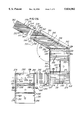
- an elongated pressure member or ram 322 is supported at the end of the table 321 by a platform or table 324 and is guided for reciprocating movement in a linear direction which forms an acute angle with the path of the boards 295 on the conveyor belts 315.
- the upper surface of the ram 322 is flush with the upper surface of the table 321, and a fluid or air cylinder 328 (FIG. 26) has a piston rod 329 (FIG. 29) for reciprocating the ram 322 between an extended position (FIG. 29) and a retracted position (FIG. 30).
- a pair of air cylinders 332 within the ram 322 are actuated to extend their piston rods upwardly for flipping or rotating the board 295 supported by the ram 322 through an angle of 90° so that the board drops downwardly onto the table 324 in front of the ram 322, as shown in FIG. 30.
- a cross rail 334 (FIG. 29) prevents the next successive or adjacent board 295 from elevating with the preceding board 295 when the cylinders 332 are actuated.
- the board 295 which has been dropped in front of the ram is pressed by the ram against the preceding board 295 for continuously producing a stack S of the boards 295 while the stack is supported by the table 324 and the adhesive beads 304 cure to connect the boards.
- the stack S of boards 295 are confined under rails 336 and between a rail 338 and an endless belt 340.
- the belt 340 extends around a set of rollers 342 and 343 and along a backup rail 344, and preferably, the belt 340 is formed by an endless belt which moves with the boards 295 and slides along the rail 344 to reduce friction between the boards and the rail 344.
- the parallel rails 338 and 334 form a predetermined angle A with the parallel rails 308 and 316.
- the angle A may be on the order of 120° so that the boards 295 forming the continuous stack S extend transversely or at a biased angle relative to the direction of movement of the stack S as the boards 295 are compressed together and advanced in a step by step manner when the ram 322 is extended.
- a pair of edge trim saws 348 are supported by a cross shaft 351 driven by an electric motor 352 or by separate motors and are positioned to cut the boards 295 forming the stack S along parallel spaced lines 354 (FIG. 31) for removing the stepped-like end portions of the boards 295 and provide the advancing continuous stack S of boards 295 with smooth parallel longitudinal edge surfaces 355. If the boards or panels 260 with preattached sheets 264 of web material are produced with inclined end surfaces, the edge trim saws 348 may be omitted.
- a traveling cut off saw 358 is driven by a motor 359 and is supported by a track (not shown) for lateral movement across the stack S of boards 295.
- the saw 358 cuts the advancing stack S of boards at longitudinally spaced intervals for successively producing the reinforced foam core board or panels 250 and to provide the boards with smooth parallel end surfaces 360.
- all of the parallel spaced webs, 254 of each foam panel or billet 250 extend at an angle of about 30° with respect to the longitudinal edge surfaces 355 so that the ends of the webs are not only exposed at opposite end surfaces 360 of the panel or billet 250 but are also exposed along the longitudinal edge surfaces 355 of the panel or billet. If the billet 250 is cut along planes parallel to the surfaces 355 or 360, the resulting panels have webs inclined rather than perpendicular to the faces of the panels.
- the ends of the webs 254 are recessed inwardly from the longitudinal edge surfaces 355 of the panel 250 as determined by the saw cuts 354.
- the edge surfaces 355 may be precisely machined without the cutting tools contacting and fraying the webs 254 to obtain precision butt joints between the longitudinal edge surfaces of adjacent panels 250 when the panels are assembled together.
- Reinforced core panels with improved structural properties and having two crossing sets of parallel webs extending at acute angles with respect to the longitudinal edge surfaces of the panel may be formed by substituting for the composite boards 260 previously formed panels 250 with overlying web sheets 42. The core panels will then have diamond- or parallelogram-shaped cells between the webs.
- FIG. 32 illustrates a modified reinforced foam core panel 370 which is constructed similar to the core panel 35 except that the parallel spaced porous fibrous webs 372 each has opposite edge portions 374 which protrude or project beyond the outer side surfaces of the foam strips or boards 376 sandwiched between the webs 372.
- the core panel 370 with the protruding web edge portions 374 may be constructed in a manner as described above in connection with the core panel 85 shown in FIG. 16, that is, by removing outer portions of the foam boards 376 to form recesses 378 between the edge portions 374 of the porous webs 372.
- the core panel 370 may also be produced by feeding a continuous strip of the flexible porous web material from a supply roll onto a continuously formed or expanded foam board having a width somewhat less than the width of the strip of web material.
- a continuous strip of flexible and porous fibrous web material may be attached by pressure sensitive adhesive to one of the fiberglass facer sheets on a continuously formed strip of foam board.
- the continuous roof board with the attached web strip are then cut at longitudinally spaced intervals and stacked to form the core panel 370, for example, with pressure sensitive adhesive attaching the web strips and foam boards together.
- the boards may be machined to form resin distribution grooves and/or fillet recesses.
- the fibers forming the projecting edge portions 374 flare outwardly to increase the bonding area between each web 372 and each skin 375.
- the resin is injected or distributed into the fiberglass skins 375 by a vacuum or differential pressure process so that the resin not only penetrates between the fibers within the skins but also between the fibers forming the porous webs 372.
- the webs 372 form integral and positive tie webs connecting the skins 375 after the resin cures.
- a reinforced foam core panel 385 is constructed by cutting the panel from a billet 90 as described above in connection with FIG. 5 or by gang sawing and assembling strips as described above.
- the panel 385 includes beveled corner fillet grooves or recesses 386 within the foam boards 387 in all three X-Y-Z directions.
- the recesses 386 expose the edge portions 388 of all of the porous flexible fiberglass webs 390 along the X-Y grid pattern on each side or face of the core panel 385 and also expose the edge portions of the interrupted webs within the core panel.
- the edge portions 388 of all webs 390 may also protrude from the faces of the foam boards at all intersections of webs to webs and all intersections of webs with skins.
- the resin which is sucked between the fibers within the skins 394 by vacuum is also sucked through the recesses 386 and between the fibers within the fiberglass webs 390 and 399.
- the resin within the recesses 386 forms fillets 398 which positively connect the web edge portions 388 to the skins 394.
- the fillets 398 also connect the support webs 399 extending within the foam boards parallel to the skins 394 to the primary webs 390 which tie the skins together.
- the support webs 399 cooperate with the rigid foam to prevent buckling of the primary structural or tie webs 390.
- one or more intermediate webs may be used with any of the core panels described herein, and may be pre-impregnated or porous and may also be orientated at an acute angle or perpendicular to the skins of the panel. It is also apparent that the X-Y grid of fillet recesses 386 within each face of the core panel 385 and the fillet recesses extending throughout the core panel, serve as resin distribution passages or channels for assuring that the resin fills all of the porous webs 390 and the fillet recesses 386.
- FIG. 36 A greatly enlarged fragmentary section of a modified reinforced foam core panel constructed in accordance with the invention is shown in FIG. 36.
- adjacent expanded foam roof insulation boards 405 are constructed as described above in connection with the panels 35 and 85 and include foam boards 406 with attached foam barrier type facer sheets 407.
- a dry, porous fibrous web material comprises adjacent layers 408 and 409 sandwiched between the facer sheets 407 and attached by layers 410 of pressure sensitive adhesive.
- the layers 408 and 409 of web material are stitched together, and each layer has parallel linear fibers extending at 45 degrees with respect to the side surfaces or skins of the panel 405.
- the layer 408 of fibers extend at 45 degrees in one direction, and the adjacent layer 409 of fibers extend at 45 degrees in the opposite direction.
- the fibers in one layer extend at 90 degrees with respect to the fibers in the adjacent layer.
- FIG. 37 illustrates the construction of a web 390 within the core panel 395 described above in connection with FIG. 35.
- Each porous and flexible fibrous web 390 includes a layer 412 of parallel linear fibers which extend at an angle of 45 degrees in one direction relative to the skins 394 and a layer 414 of parallel linear fibers which extend at an angle of 45 degrees in the opposite direction with respect to the skins 394.
- the layers 412 and 414 are separated by parallel spaced bundles 416 of linear fibers which extend at right angles or normal to the skins 394 and define therebetween resin distribution channels.
- the fiber layers 412 and 414 and bundles 416 of fibers are stitched together to form a porous web which is attached to the adjacent foam boards, preferably by pressure sensitive adhesive.
- each web 390 is fully impregnated with resin and forms an integral and positive tie web connection between the skins 394.
- the spacer bundles may also be oriented parallel or at an acute angle to the skins depending on the desired direction of resin flow.
- the fibrous reinforcement layers may be separated by random mat, scrim, or other fibrous material having crossing layers of fibers with interconnected interstices conducive to relatively free flow of resin through the plane of the web. Resin flow through the webs may also be improved by leaving gaps in the fibers of the primary stitched reinforcement layers which comprise the webs, rather than by separating the primary layers by spaced bundles as described above.
- the separator layer may comprise a sheet of resin-impermeable material, which may be embossed with resin distribution channels and perforated to facilitate the flow of resin to both sides of the web.
- the webs 390 effectively resist the shear within the core. That is, the plus and minus 45 degree orientation of the glass fibers within the layers 408 and 409 greatly increase the structural and cost efficiency of the reinforcing webs 390.
- the compressive strength of a sandwich panel containing the web reinforced core may be increased by incorporating into the webs additional reinforcing fibers oriented in a direction generally perpendicular to the sandwich panel skins, to take advantage of the higher compressive properties of the fibers in the direction of their length.
- these fibers may be caused to protrude from the surface of the core, as previously described herein.
- the webs may incorporate protruding thin needle-like composite fibers of sufficient stiffness to penetrate between the individual fibers or fiber bundles of the skin reinforcements when the skins are pressed against the core.
- a curable resin is applied to flow through the fibrous reinforcements of the skins and webs, the interpenetrating fibers provide an enhanced structural bond.
- the porous, fibrous webs of FIGS. 36 and 37 may be pre-attached to the outside of a non-porous facer sheet 407, to be used in the manufacture of continuous process foam insulation boards, as previously described. If these non-porous facer sheets 407 are pre-attached to both sides of porous webs 390 prior to foaming, the resulting foam board may be stacked and bonded to like insulation boards using liquid adhesives which will attach to the barrier facers without penetrating them.
- the porosity of the structural web fibers is maintaned for subsequent resin flow edgewise through the web fibers during impregnation of sandwich panel skins.
- the barrier facers may comprise thermoplastic material, such as polypropylene, with a softening temperature sufficiently low that the foam boards will adhere together into billets if stacked under modest pressure immediately after forming the foam boards 40, while the exotherm temperature of the foaming chemicals raises the temperature of the stack high enough to fuse adjacent barrier sheets together.
- thermoplastic material such as polypropylene
- All of the reinforced core panels described and illustrated herein may be characterized as assemblies of pieces of foam plastic separated by flexible web material which intersects the faces of the core and which in many preferred embodiments is porous. It is understood that the foam pieces may be cut from larger boards or billets or may be molded, and that they may be of a wide variety of shapes, as desired for structural, processing or other reasons. If desired, foam pieces which have been cut from boards may be coated with a thin layer of impermeable resin in order to seal the surface of the foam and prevent the flow of excess resin into the cut-cell surface of the foam pieces. Examples of panels constructed of various foam shapes, with corresponding web patterns, are shown in fragmentary plan views in FIGS. 38-40.
- FIG. 38 The rectangular grid configuration of a core panel 418 (FIG. 38) is constructed by iterative stacking and cutting of flat foam boards and planar sheets of web material, as previously described herein, to form foam pieces 420 and porous strips or webs 422.
- FIG. 38 also illustrates fillet recesses 424 in the foam pieces adjacent the edge portions of the intersecting strips or webs, as well as flared or expanded web edge portions 426.
- the expanded edge portions 426 are formed by pressing core panels having protruding web edges, as shown in FIG. 32, against the continuous webs during the process of core panel assembly described above.
- the web edge fillet recesses 424 are provided in the opposite side surfaces of the core panel for improved web attachment to sandwich panel skins.
- the foam pieces or blocks 420 shown in FIG. 38 are of square cross section as seen in the plan view. Core panels may also be produced in which the foam pieces are of hexagonal, triangular or other cross-section. In the embodiment or core panel 430 shown in FIG. 39, the foam blocks or pieces 434 are triangular.
- the thin, porous, fibrous webs 432 which separate the foam pieces may be adhered as separate webs to each face of the blocks or may, as shown, be wrapped around each foam piece 434, forming double layer webs.
- the web material may also be sized to protrude beyond the side surfaces of the core panel and is secured to the pieces by staples, adhesives or otherwise. The pieces are then assembled together as shown in FIG. 39, and attached to one another to form the core panel 430.
- FIG. 39 also illustrates web edge fillet recesses 437 provided in the sides of the foam blocks which form the opposite side surfaces of the core panel, for improved web attachment to sandwich panel skins.
- Reinforced foam core panels may also be constructed by conforming flexible web sheets to successive layers of foam pieces or boards of square, hexagonal, triangular or other cross-section.
- a core panel 444 includes a layer of foam pieces or boards or blocks 446 which are of square cross-section and are aligned with their corners opposing the corners of adjacent blocks.
- Strips or webs 448 of porous flexible web material are drawn across the exposed faces of the blocks and are mechanically conformed to the profile of the layer of blocks by pressing each web against the preceding layer of foam blocks at the corners where the webs intersect.
- the web material which may be wider than the blocks so that edge portions protrude from the side surfaces of the core panel, is adhesively bonded to the blocks while maintaining the porosity of the web material.
- a layer of web-covered pieces or blocks (FIG. 40) may be advanced, and successive layers of foam pieces or blocks and flexible webs applied to produce a continuous core panel.
- the foam pieces 446 may be provided with fillet recesses 454 adjacent the web edge portions.
- Fillet recesses 452 may be provided in the foam pieces 446 adjacent the lines of tangent contact between adjacent webs.
- the resin flowing into the core during the process of attaching sandwich panel skins to the core panel fills the recesses 452 to form expanded bond areas for the resin to connect the tangent webs to each other for improved transfer of structural loads from web to web throughout the core panel.
- FIG. 41 shows a honeycomb-pattern core panel 455 in which porous and fibrous web strips 457 are conformed to three adjacent faces of foam pieces 459 each having hexagonal cross section so that individual web strips 457 describe a corrugated pattern and alternating planar segments of each web strip are attached by surface contact adhesive to corresponding line segments of contiguous web strips.
- a variety of methods other than direct adhesive bonding of foam pieces to web material may be employed to unitize the core panel assembly.
- rows of spaced fiberglass yarns impregnated with hot-melt or other fast setting adhesive are adhered under pressure to one or both faces of the core panel 370 and extend from edge to edge of the said core panel in a direction perpendicular to the porous webs 372.
- side pressure is applied to the core panel to compress together the foam strips 376 and web strips 372.
- the fiberglass yarn which has high tensile strength and has adhered to both the foam and the edge portions of the webs, holds the strips together tightly to maintain panel width and to minimize excess resin between the strips.
- This yarn method of unitizing the core panel also reduces the likelihood of foam-to-web separation during handling and shipping of the core panel, especially with thin panels. If additional flexibility is required in the core panel 370 to permit bending to fit a curved surface, the fiberglass yarn may be applied to only one face of the core panel.
- Other forms of core panel such as those shown in FIGS. 38-41, may be similarly unitized, using crossing fibers fiberglass scrim cloth having crossing fibers, for example in a pattern of one-half inch squares.
- porous and fibrous web strips 457 may be faced on both sides with non-porous barrier membranes before forming the hollow-cell panel, to prevent subsequent penetration of the porous webs by expanding foam.
- the membranes may be of thermoplastic material, such as PET, which may be heat formed to yield a corrugated pattern having relatively straight line segments and precise corners.
- linear webs faced if necessary with membranes of kraft paper, plastic film or other suitable foam barrier material, may be adhered along spaced lines into layered blocks which are subsequently expanded to form cells of generally hexagonal, but less regular shape.
- foam may be introduced by existing methods for pouring foam into honeycomb cells and curing it.
- Porous-web foam core panels produced by introducing foam into a cellular matrix as described herein may require face sanding, in order to remove foam from the edges of the webs and thus facilitate the subsequent free flow of resin throughout the webs.
- a slab of cured foam which is sufficiently weak to be cut by the cell walls may be pressed into the panel. It may be necessary to provide web membrane layers comprised of thin, stiff material such as rigid plastic or phenolic impregnated paper, to make the webs of the open cell panel sufficiently stiff to cut the foam slab rather than to buckle under pressure.
- FIG. 42 illustrates a preferred embodiment having porous webs 62 comprised of reinforcing material such as stitched or woven fiberglass fabric which is not significantly compressible.
- Core panel 470 is comprised of porous fibrous web strips 474, which are adhesively attached to foam strips 472.
- the foam strips 472 have been provided with longitudinal slots extending most of the way through the strips from the inside face of the core panel 470 and which taper to a point near the outside face of the said core panel.
- the angle of the beveled taper 476 is calculated to close tightly when the core panel 470 is bent to conform to a cylindrical surface of given radius.
- Spaced rows of fiberglass yarns 478 which have been impregnated with hot melt or other adhesive extend across the outside face of the core panel 470 in a direction perpendicular to the porous webs 474 and are adhered to the faces of the foam strips 472 and the edge portions of the webs 474.
- a second set of fiberglass yarns 478 may be adhered to the inside face of the core panel to enhance the stability of the core panel during handling and shipping.
- the core panel may be provided with protruding web edge portions and web end fillet recesses, as described elsewhere herein, to enhance the bond between webs 474 and sandwich panel skins.
- the individual foam strips may be of trapezoidal cross section so that their side surfaces adjacent the porous web strips are at an acute angle, rather than perpendicular to, the faces of the core, and a backer sheet is adhered to the outside surface as just described.
- a radius may be machined into the faces of the foam strips which comprise the faces of the core panel, so that the surfaces of the resulting cylinder describe true, rather than segmented, circles.
- the core panel 470 may be used to form a sandwich panel of cylindrical shape, such as a pipe or tank wall, as illustrated in FIG. 43.
- An inner skin 482 of porous fibrous reinforcing material, such as fiberglass fabric, is wrapped around a cylindrical mandrel 480, with the ends of the fabric overlapping to form a structural splice.
- Core panel 470 of predetermined width to match the circumference of the mandrel 480, is wrapped around the said mandrel so that opposing edges of the core panel touch each other to form a cylindrical core panel. If fiberglass yarns 478 have been previously applied to the inside of the core panel 470, the yarns will crumple into the foam strips 472 to permit the tapered slots 476 to close.
- An outer skin 484 of porous fibrous reinforcing material such as fiberglass fabric is wrapped around the core panel 470 with the ends of the fabric overlapping to form a structural splice and to complete the unimpregnated sandwich panel 486. If preferred for structural or manufacturing reasons, mandrel 480 may be rotated, and inner skin 482 and/or outer skin 484 may be replaced by filament wound porous fibrous reinforcing rovings.
- panel 486 After the dry sandwich panel 486 has been formed, as shown in FIG. 43, panel 486 is enclosed in as vacuum bag or mold and a curable adhesive resin is caused to flow throughout the porous fibrous reinforcements of skins 482 and 484 and webs 474.
- the resin cures to form a thermally insulated, double-walled cylindrical composite structure having longitudinal reinforcing webs 474 extending radially between the inner and outer skins.
- mandrel 480 is removed from the composite structure.
- FIG. 44 illustrates a preferred method of forming core panels 418 shown in FIG. 38.
- Both faces of rigid foam plastic boards 387 are provided with beveled grooves 490 by a gang grooving apparatus (not shown), which employs spaced abrasive or toothed cutters on a rotating arbor to form the grooves.
- Sheets of porous fibrous web material 492 are adhered to one face of the foam boards 387 while maintaining substantial porosity in the web material, as previously described herein.
- the foam boards 387 with attached web sheets 492 are then fed into the gang saw apparatus as shown in FIG. 44.
- Spaced sets 494 of toothed circular saw blades are mounted on rotating arbor 496 and aligned by tubular spacers 495 with the centers of the grooves 490.
- Each set 494 of saw blades includes a center blade 498 of sufficient diameter to cut the web sheets 494 and two side saw blades 500, which extend into the grooves 490 but do not contact the web sheet 492.
- the center blades 498 are ground and mounted on arbor 496 so that the saw teeth present a negative hook angle to the fibrous web sheets 492, in order to split or break, and also fray, the fibers without pulling them out of the fabric.
- Side blades 500 remove the edge portions of the foam strips 497 with attached webs, so that the edge portions of the webs 499 protrude from the edges of the said foam strips adjacent the remaining portion of the beveled grooves 490.
- the foam strips with attached webs are then arranged in stacks, with each foam strip 497 separated by a web strip 499, and unitized into web reinforced core panels by methods described elsewhere herein.
- the resulting core panels have unidirectional webs with both protruding web edge portions and web edge fillet recesses.
- An important object of the present invention is to produce sandwich panels of enhanced structural properties by applying improved web-to-web and web-to-skin structural attachment to all core panels having exposed foam side surfaces and reinforcing webs which intersect those surfaces.
- This improved structural attachment is achieved by incorporating into the core panel porous webs, webs with protruding edge portions, thin stiff needle-like fiber penetrating webs which protrude in a direction perpendicular to the skins and penetrate the skins, web edge fillet recesses, or any combination of these structural features.
- the enhanced attachment properties of the invention are effective irrespective of the geometric arrangement of foam pieces and webs within the core panel, of the foam and web assembly technique, or of the method used to unitize foam pieces and web material. It is also understood that these features may be incorporated into web-reinforced core panels in which pieces of balsa wood are substituted for the plastic foam.
- web edge portions may be made to protrude by sizing webs to exceed the thickness of the foam pieces or by recessing the foam faces, and fillet recesses may be provided by molding the foam pieces or by recessing or beveling the foam pieces adjacent the web edge portions.
- the web reinforced panels of the present invention are designed for use as structural cores in sandwich panels having generally parallel skins.
- the opposite side surfaces of the core panels, which are attached to the sandwich panel skins commonly describe generally parallel planes.
- some sandwich panels have cores of non-uniform thickness.
- core panels of corresponding non-uniform thickness by assembling foam pieces and porous, fibrous webs whose dimensions vary correspondingly, or by cutting core panels or billets of oversize depth to the required non-uniform dimensions.
- sandwich panel boat hulls are generally not flat or rectangular in shape, even though the core thickness may be uniform. If a large number of core panels having non-rectangular opposite side surfaces is required for a given application, it may be more efficient to produce the panels by using foam pieces and web sheets whose shape and/or pattern of assembly yields the desired non-rectangular panels.
Abstract
Description
Claims (10)
Priority Applications (1)
| Application Number | Priority Date | Filing Date | Title |
|---|---|---|---|
| US08/775,403 US5834082A (en) | 1992-05-04 | 1996-12-30 | Reinforced foam cores and method and apparatus of production |
Applications Claiming Priority (4)
| Application Number | Priority Date | Filing Date | Title |
|---|---|---|---|
| US87798592A | 1992-05-04 | 1992-05-04 | |
| US08/102,892 US5462623A (en) | 1992-05-04 | 1993-08-06 | Method of production of reinforced foam cores |
| US08/503,205 US5589243A (en) | 1992-05-04 | 1995-07-17 | Reinforced foam cores and method and apparatus of production |
| US08/775,403 US5834082A (en) | 1992-05-04 | 1996-12-30 | Reinforced foam cores and method and apparatus of production |
Related Parent Applications (1)
| Application Number | Title | Priority Date | Filing Date |
|---|---|---|---|
| US08/503,205 Continuation-In-Part US5589243A (en) | 1992-05-04 | 1995-07-17 | Reinforced foam cores and method and apparatus of production |
Publications (1)
| Publication Number | Publication Date |
|---|---|
| US5834082A true US5834082A (en) | 1998-11-10 |
Family
ID=27379435
Family Applications (1)
| Application Number | Title | Priority Date | Filing Date |
|---|---|---|---|
| US08/775,403 Expired - Lifetime US5834082A (en) | 1992-05-04 | 1996-12-30 | Reinforced foam cores and method and apparatus of production |
Country Status (1)
| Country | Link |
|---|---|
| US (1) | US5834082A (en) |
Cited By (121)
| Publication number | Priority date | Publication date | Assignee | Title |
|---|---|---|---|---|
| US5989666A (en) * | 1998-06-26 | 1999-11-23 | David M. Hadden | Aesthetic structure with simulated leading |
| US6444073B1 (en) * | 1997-04-25 | 2002-09-03 | Brunswick Corporation | Thermoplastic multi-layer composite structure |
| US6503426B1 (en) | 2000-07-06 | 2003-01-07 | David James Horwitz | Process for making foam laminates |
| JP2003518453A (en) * | 1999-12-28 | 2003-06-10 | ウェブコア テクノロジーズ,インコーポレイティド | Fiber reinforced composite core and panel |
| US6586110B1 (en) | 2000-07-07 | 2003-07-01 | Delphi Technologies, Inc. | Contoured metal structural members and methods for making the same |
| US20030170441A1 (en) * | 2002-03-05 | 2003-09-11 | Boyle Frederick P. | Composite-structure core |
| US6635820B1 (en) * | 1999-04-16 | 2003-10-21 | Siemens Aktiengesellschaft | Sheilding device for an electrical module support |
| US6645333B2 (en) | 2001-04-06 | 2003-11-11 | Ebert Composites Corporation | Method of inserting z-axis reinforcing fibers into a composite laminate |
| US6649096B2 (en) * | 2001-07-30 | 2003-11-18 | Lockheed Martin Corporation | Method of making a filled honeycomb core composite structure |
| WO2003103961A1 (en) * | 2002-06-11 | 2003-12-18 | Ross Mervyn Nosworthy | Composite board and process for making the board |
| US6676862B2 (en) | 1999-09-15 | 2004-01-13 | Advanced Building Systems, Inc. | Method for forming lightweight concrete block |
| US6676785B2 (en) | 2001-04-06 | 2004-01-13 | Ebert Composites Corporation | Method of clinching the top and bottom ends of Z-axis fibers into the respective top and bottom surfaces of a composite laminate |
| US20040049999A1 (en) * | 2002-09-12 | 2004-03-18 | Kevin Krieger | Curved wall panel system |
| US20040058141A1 (en) * | 2002-09-20 | 2004-03-25 | Shutic Jeffrey R. | Powder coating systems |
| US20040067352A1 (en) * | 2002-10-04 | 2004-04-08 | Hagerman Joseph W. | Rigid composite building materials and assemblies utilizing porous and non-porous rigid foamed core materials |
| FR2848143A1 (en) * | 2002-12-04 | 2004-06-11 | Alain Legal | Laminated component manufacturing procedure uses perforated wood-based panel applied over protective and resin-impregnated reinforcing layers |
| US20040128947A1 (en) * | 2001-05-17 | 2004-07-08 | Toshihiro Ito | Sound-proof wall made of frp, and method of producing the same |
| US20040134134A1 (en) * | 2002-10-22 | 2004-07-15 | Back Mark A. | Conservatory roof with a soffit system |
| US6770374B1 (en) | 1998-06-05 | 2004-08-03 | Basf Aktiengesellschaft | Composite elements containing compact polyisocyanate polyaddition products |
| US20040163328A1 (en) * | 2003-02-25 | 2004-08-26 | Riley John Michael | Insulated glazed roofing system |
| US6790537B1 (en) | 1999-03-30 | 2004-09-14 | Basf Aktiengesellschaft | Composite elements containing polyisocyanate-polyaddition products |
| US20040177579A1 (en) * | 2003-03-10 | 2004-09-16 | Innovative Construction Technologies, Inc. | Reinforced foam articles |
| US20040188025A1 (en) * | 2000-11-15 | 2004-09-30 | Toyota Motor Sales, U.S.A., Inc. | One-piece closed-shape structure and method of forming same |
| US6821638B2 (en) | 2000-07-07 | 2004-11-23 | Delphi Technologies, Inc. | Shaped contoured crushable structural members and methods for making the same |
| US6820455B1 (en) | 2001-09-17 | 2004-11-23 | Wesley Allen Bainter | Metal working machine |
| US6824851B1 (en) | 1999-10-08 | 2004-11-30 | Milwaukee Composites, Inc. | Panels utilizing a precured reinforced core and method of manufacturing the same |
| US20050074593A1 (en) * | 2000-12-27 | 2005-04-07 | Webcore Technologies, Inc. | Fiber reinforced composite cores and panels |
| US20050142333A1 (en) * | 2003-12-30 | 2005-06-30 | Montagna John C. | Method of manufacturing composite vehicle panels |
| US20050140177A1 (en) * | 2003-12-30 | 2005-06-30 | Montagna John C. | Method of manufacturing composite vehicle panels |
| US20050166479A1 (en) * | 2004-02-03 | 2005-08-04 | Park Lane Conservatories Ltd | Eaves beam with framing |
| US6995099B1 (en) * | 1999-03-23 | 2006-02-07 | Toray Industries, Inc. | Composite reinforcing fiber base material, preform and production method for fiber reinforced plastic |
| US6996860B1 (en) * | 2001-06-06 | 2006-02-14 | Blake Raymond A | Construction protective covering |
| US7056576B2 (en) | 2001-04-06 | 2006-06-06 | Ebert Composites, Inc. | 3D fiber elements with high moment of inertia characteristics in composite sandwich laminates |
| US7055441B2 (en) | 2003-03-27 | 2006-06-06 | Gunderson, Inc. | Counterbalanced deck for railroad freight car |
| US20060124853A1 (en) * | 2004-12-10 | 2006-06-15 | Andrew Corporation | Non-contact surface coating monitor and method of use |
| US7105071B2 (en) | 2001-04-06 | 2006-09-12 | Ebert Composites Corporation | Method of inserting z-axis reinforcing fibers into a composite laminate |
| GB2424611A (en) * | 2005-03-31 | 2006-10-04 | Colin Hilton | Production of laminated articles |
| US20070044407A1 (en) * | 2005-08-30 | 2007-03-01 | Specialty Hardware L.P. | Fire-retardant cementitious shear board having metal backing with tab for use as underlayment panel for floor or roof |
| USRE39554E1 (en) | 1994-08-29 | 2007-04-10 | Spectrum Solutions, Ltd. | Reinforced composite structure |
| US20070090562A1 (en) * | 2005-10-25 | 2007-04-26 | Hawkins Robert D | Controlled delta pressure bulk resin infusion system apparatus and method |
| US7223457B1 (en) | 1999-11-04 | 2007-05-29 | Basf Aktiengesellschaft | Composite elements |
| US20070152105A1 (en) * | 2005-12-13 | 2007-07-05 | Eads Deutschiand Gmbh | Composite fiber component produced by braiding |
| WO2007104577A1 (en) * | 2006-03-16 | 2007-09-20 | Innovida Factories, Ltd. | Sandwich element |
| US20080124530A1 (en) * | 2006-09-22 | 2008-05-29 | Paradis Duane R | Polymer-based composite structural underlayment board and flooring system |
| US20080120932A1 (en) * | 2006-09-22 | 2008-05-29 | Paradis Duane R | Polymer-based composite structural sheathing board and wall and/or ceilling system |
| US20080127607A1 (en) * | 2006-12-04 | 2008-06-05 | Custom Components Of Eagle River, Inc. | Building panels |
| US20080141897A1 (en) * | 2006-10-30 | 2008-06-19 | Gunderson, Llc | Energy absorber for counterbalance mechanism |
| US20080148663A1 (en) * | 2006-10-03 | 2008-06-26 | Peede J Edward | Interior structural panel |
| US20080174149A1 (en) * | 2007-01-18 | 2008-07-24 | Simms Adrian R | Structural insulation panel |
| US20080193712A1 (en) * | 2007-02-10 | 2008-08-14 | Desjardins Paul A | Structurally insulated - integrated building panel |
| US20090029083A1 (en) * | 2005-05-31 | 2009-01-29 | Kyoraku Co., Ltd. | Resin panel and method of producing the same |
| US20090165411A1 (en) * | 2006-12-04 | 2009-07-02 | Schiffmann Gerhard P | Method of fabricating building wall panels |
| US20090202776A1 (en) * | 2008-02-12 | 2009-08-13 | Brandon Anthony S | Fiber reinforced core panel |
| US20090252917A1 (en) * | 2005-05-27 | 2009-10-08 | Airbus Deutschland Gmbh | Reinforcement of cellular materials |
| US20090255204A1 (en) * | 2008-04-11 | 2009-10-15 | Innovida Holdings, Inc. | Straight joint for sandwich panels and method of fabricating same |
| US20090286134A1 (en) * | 2008-05-13 | 2009-11-19 | Hyundai Motor Company | End plate for fuel cell stack and method for manufacturing the same |
| US20090313926A1 (en) * | 2008-06-20 | 2009-12-24 | Innovida Factories, Ltd. | Connection for sandwich panel and foundation |
| US20090320387A1 (en) * | 2008-06-27 | 2009-12-31 | Innovida Factories, Ltd. | Sandwich panel ground anchor and ground preparation for sandwich panel structures |
| US20100005732A1 (en) * | 2008-07-10 | 2010-01-14 | Innovida Holdings, Inc. | Building roof structure having a round corner |
| US20100014935A1 (en) * | 2008-07-21 | 2010-01-21 | Fred Jevaney | Reinforced bulkheads and methods of making same |
| WO2010022427A1 (en) * | 2008-08-27 | 2010-03-04 | Johann Berger | Method and device for producing cross-ply slotted-board panels |
| US20100050542A1 (en) * | 2008-09-04 | 2010-03-04 | Innovida Factories, Ltd. | System and method of forming at least a portion of a reinforced roof structure from sandwich panels |
| JP2010509101A (en) * | 2006-11-09 | 2010-03-25 | ウェブコア アイピー,インコーポレイティド | Fiber reinforced composite core and panel |
| US7731046B2 (en) | 2001-04-06 | 2010-06-08 | Ebert Composites Corporation | Composite sandwich panel and method of making same |
| US20100196652A1 (en) * | 2009-02-03 | 2010-08-05 | Demien Jacquinet | Quasi-isotropic sandwich structures |
| US20100192349A1 (en) * | 2005-02-24 | 2010-08-05 | Matthew Vishnick | Window removal device |
| US7785693B2 (en) | 2001-04-06 | 2010-08-31 | Ebert Composites Corporation | Composite laminate structure |
| US20100263504A1 (en) * | 2007-11-21 | 2010-10-21 | Airbus Operations Gmbh | Device and method for producing a reinforced foam material |
| US20100266833A1 (en) * | 2000-12-27 | 2010-10-21 | Webcore Technologies, Inc | Fiber reinforced composite cores and panels |
| US7836641B2 (en) | 2002-12-16 | 2010-11-23 | Park Lane Conservatories Ltd. | Multi-piece eaves beam for preassembled glazed roof system |
| US20110011018A1 (en) * | 2009-07-15 | 2011-01-20 | Frank Johnson | Modular construction mold apparatus and method for constructing concrete buildings and structures |
| US7897235B1 (en) * | 2005-07-27 | 2011-03-01 | Milwaukee Composites, Inc. | Fire retardant panel apparatus and method of making and using same |
| US20110061332A1 (en) * | 2009-09-17 | 2011-03-17 | Hettick Steven A | Modular Tower Apparatus and Method of Manufacture |
| US20110081514A1 (en) * | 2009-10-01 | 2011-04-07 | Webcore Ip, Inc. | Composite cores and panels |
| US20110081518A1 (en) * | 2009-10-02 | 2011-04-07 | Webcore Ip, Inc. | Composite cores and panels |
| US20110120039A1 (en) * | 2009-11-24 | 2011-05-26 | Kysor Panel Systems, Division Of Welbilt Walk-Ins Lp | High strength composite framing members |
| US7972698B2 (en) | 2004-10-21 | 2011-07-05 | Graftech International Holdings Inc. | Carbon foam core panels |
| WO2012031188A2 (en) * | 2010-09-03 | 2012-03-08 | Cvg Management Corporation | Rigidity controlled fiberglass |
| FR2967607A1 (en) * | 2010-11-18 | 2012-05-25 | Jean Francois Leger | Core for sandwich-type structure that is useful in building e.g. boat, comprises upper portion formed of polyurethane foam elements independent from each other, and lower portion constituted of flexible support on which are fixed elements |
| ITFI20110008A1 (en) * | 2011-01-18 | 2012-07-19 | Tecnowall S R L | SANDWICH-TYPE PANEL AND PROCEDURE FOR THE PRODUCTION OF A PANEL SIFFATURE. |
| CN102639317A (en) * | 2009-12-04 | 2012-08-15 | 波音公司 | Sandwich structure having arrestment feature and method of making the same |
| US20120225236A1 (en) * | 2011-03-03 | 2012-09-06 | James Edward Cox | Composite Building Panel and Method |
| US20120247042A1 (en) * | 2011-03-28 | 2012-10-04 | Owens Corning Intellectual Capital Llc | Board with pre-applied sealing material |
| WO2013013809A1 (en) * | 2011-07-25 | 2013-01-31 | Plantaciones De Balsa Plantabal S.A. | Method for producing flexible end grain balsa panels |
| WO2013026925A1 (en) * | 2011-08-25 | 2013-02-28 | Bcomp Ag | A method for manufacturing a composite material, and a sheet made of this composite material |
| US8534028B2 (en) | 2010-10-08 | 2013-09-17 | Composite Panel Systems, Llc | Building panels |
| US8607531B2 (en) | 2008-12-18 | 2013-12-17 | Composite Panel Systems, Llc | Building panel assemblies and methods of use in wall structures |
| US8641848B2 (en) | 2011-03-14 | 2014-02-04 | Milliken & Company | Method and apparatus for combining elongated strips |
| US8646183B2 (en) | 2011-03-14 | 2014-02-11 | Milliken & Company | Process for forming a fiber reinforced core panel able to be contoured |
| US8663791B2 (en) | 2011-04-04 | 2014-03-04 | Milliken & Company | Composite reinforced cores and panels |
| WO2014144766A1 (en) * | 2013-03-15 | 2014-09-18 | Milwaukee Composites, Inc. | Ribbed balsa |
| US8875475B2 (en) * | 2013-03-14 | 2014-11-04 | Millport Associates S.A. | Multiple panel beams and methods |
| US8904737B2 (en) | 2008-12-18 | 2014-12-09 | Composite Panel Systems, Llc | Building panel assemblies and methods of use in wall structures |
| US20150125686A1 (en) * | 2012-03-26 | 2015-05-07 | Airex AG Corporation of Switzerland | Structural element and method for the production thereof |
| US9061687B2 (en) | 2012-11-05 | 2015-06-23 | Gunderson Llc | Railroad car for carrying motor vehicles |
| US20150225949A1 (en) * | 2014-02-07 | 2015-08-13 | Sheng-Liang Chen | Thinned building board |
| US20160003404A1 (en) * | 2013-02-28 | 2016-01-07 | Panasonic Intellectual Property Management Co., Ltd. | Heat insulating structure using aerogel |
| WO2016041836A1 (en) * | 2014-09-18 | 2016-03-24 | Basf Se | New composite article |
| US20160177530A1 (en) * | 2014-12-17 | 2016-06-23 | Richard and Carolyn Koberg Living Trust | Pad for support of equipment and method of producing same |
| EP3090871A1 (en) | 2015-05-05 | 2016-11-09 | Sunrez Corp. | Fiber reinforced core |
| US9493938B2 (en) | 2008-12-18 | 2016-11-15 | Composite Panel Systems, Llc | Building panel assemblies and methods of use in wall structures |
| US9681763B2 (en) * | 2015-06-01 | 2017-06-20 | Knoll, Inc. | Privacy screen apparatus |
| US9835429B2 (en) * | 2015-10-21 | 2017-12-05 | Raytheon Company | Shock attenuation device with stacked nonviscoelastic layers |
| WO2018035022A1 (en) * | 2016-08-15 | 2018-02-22 | Bradford Company | Single foil ribbed sheet, method and apparatus of making same and products produced therewith |
| US20180148930A1 (en) * | 2015-05-28 | 2018-05-31 | Regin Eysturoy Grimsson | Building Element of Mineral Wool and Fiber-Reinforced Plastic |
| CN109177428A (en) * | 2018-08-08 | 2019-01-11 | 广东同创科鑫环保有限公司 | A kind of production method of composite board |
| US20190136515A1 (en) * | 2017-11-07 | 2019-05-09 | Johns Manville | Foundation waterproofing system and method |
| WO2020051140A1 (en) * | 2018-09-04 | 2020-03-12 | Hanwha Azdel, Inc. | Composite articles with a variable basis weight and uniform thickness |
| US20200256019A1 (en) * | 2018-05-30 | 2020-08-13 | Strata Products Worldwide, Llc | Sheet for a Mine Floor or a Road, and Method |
| US10751971B1 (en) | 2019-04-19 | 2020-08-25 | Goodrich Corporation | Edge damage tolerant heated and unheated composite panels with rotated honeycomb edge pieces |
| CN111605256A (en) * | 2020-04-29 | 2020-09-01 | 中材科技风电叶片股份有限公司 | Composite structure, manufacturing method thereof, and blade |
| CN112476576A (en) * | 2020-10-26 | 2021-03-12 | 株洲时代新材料科技股份有限公司 | Design and cutting method for blunt tail core material of wind power blade |
| CN113635646A (en) * | 2021-07-28 | 2021-11-12 | 哈尔滨工业大学 | Composite material cover body with wave-absorbing stealth and sealing waterproof functions and preparation method thereof |
| US20220097313A1 (en) * | 2018-11-29 | 2022-03-31 | Deutsches Zentrum für Luft- und Raumfahrt e.V. | Method for producing a test specimen |
| US11339569B2 (en) * | 2017-04-18 | 2022-05-24 | Nexgen Composites Llc | Unitized construction panel |
| US11364858B2 (en) | 2018-09-04 | 2022-06-21 | Hanwha Azdel, Inc. | Core layers and composite articles with a variable basis weight |
| US20220389903A1 (en) * | 2019-11-28 | 2022-12-08 | Envision Energy CO.,LTD | Material core for wind turbine blade and method for manufacturing the same |
| US20230102696A1 (en) * | 2019-12-02 | 2023-03-30 | Hokuriku Color Foam Co., Ltd. | Method for manufacturing fiber-reinforced resin structure |
| FR3130676A1 (en) * | 2021-12-22 | 2023-06-23 | Gaztransport Et Technigaz | Continuous production method of an insulation board by a production machine |
| US11761420B2 (en) * | 2018-07-23 | 2023-09-19 | Siemens Games Renewable Energy A/S | Composite material, a wind turbine blade, a wind turbine and a method for producing a composite material |
| US11795688B2 (en) | 2020-07-01 | 2023-10-24 | Composite Panel Systems Llc | Structural building panels and panel components, panel assemblies, methods of making, and methods of using |
Citations (47)
| Publication number | Priority date | Publication date | Assignee | Title |
|---|---|---|---|---|
| GB245458A (en) * | ||||
| US2053173A (en) * | 1930-05-14 | 1936-09-01 | Astima Eugene | Shadow producing screen for luminous projections and other applications and process for its manufacture |
| US2062590A (en) * | 1935-09-30 | 1936-12-01 | Roy W Lundquist | Method of creating a desing and article |
| GB548027A (en) * | 1941-07-23 | 1942-09-22 | George Donald Skinner | An improved method of manufacturing sheets or panels of transparent material with embedded layers of opaque or semi-opaque material |
| GB559527A (en) * | 1942-07-10 | 1944-02-23 | Ernest Platton King | A method of building-up composite walls, sheets or structures containing veneer |
| CA446910A (en) * | 1948-02-24 | Bendel Gibbons Henry | Laminated article | |
| US2493032A (en) * | 1945-07-26 | 1950-01-03 | Jr George B Rheinfrank | Gridded core material and method |
| US3070475A (en) * | 1958-06-09 | 1962-12-25 | Monsanto Chemicals | Laminated structures |
| CA658023A (en) * | 1963-02-19 | A. Mcelhone Charles | Foamed polymeric structures | |
| US3230995A (en) * | 1960-12-29 | 1966-01-25 | Owens Corning Fiberglass Corp | Structural panel and method for producing same |
| US3243492A (en) * | 1962-02-08 | 1966-03-29 | Allied Chem | Stabilized panel production |
| US3246058A (en) * | 1961-02-28 | 1966-04-12 | Allied Chem | Method for producing reinforced foam laminate structures |
| US3264153A (en) * | 1963-01-14 | 1966-08-02 | C J Rodman | Method of producing composite coreboard |
| US3339326A (en) * | 1964-07-06 | 1967-09-05 | Midland Ross Corp | Panel with triangular cross-section foam core elements |
| US3526556A (en) * | 1966-12-06 | 1970-09-01 | Berner Ind Inc | Apparatus and method for the continuous production of slabs or sheets composed of foamed polymeric material having a cellular core |
| US3544417A (en) * | 1969-04-28 | 1970-12-01 | Unicor Inc | Cellular foam core assembly |
| US3549449A (en) * | 1967-09-29 | 1970-12-22 | Dow Chemical Co | Method for the preparation of a composite plastic - containing product and article produced thereby |
| US3697633A (en) * | 1970-07-21 | 1972-10-10 | Howard M Edgar | Structural core |
| US3708385A (en) * | 1971-06-21 | 1973-01-02 | Ethyl Corp | Sandwich panel construction |
| US3733235A (en) * | 1971-07-22 | 1973-05-15 | Westvaco Corp | Fabrication of laminated structural panels |
| US3734811A (en) * | 1967-07-12 | 1973-05-22 | Exxon Research Engineering Co | Laminated construction of cellular plastic material |
| US3750355A (en) * | 1971-04-28 | 1973-08-07 | Blum Bau Kg | Facade composite panel element |
| US3841958A (en) * | 1971-09-02 | 1974-10-15 | R Delorme | Reinforced structural element and method of making the same |
| US3867238A (en) * | 1972-04-18 | 1975-02-18 | Chemacryl Plastics Ltd | Flexile core material for laminated structures and method of producing the same |
| US3906137A (en) * | 1971-03-25 | 1975-09-16 | Roehm Gmbh | Laminate having a compressed foam core |
| US4042746A (en) * | 1975-11-07 | 1977-08-16 | The John Z. Delorean Corporation | Composite material and method of forming |
| US4048365A (en) * | 1974-05-24 | 1977-09-13 | Hoover William H | Armor structure formed from plastic laminates |
| US4093762A (en) * | 1974-04-30 | 1978-06-06 | John Kiefer | Method of making a hardcore honeycomb panel and honeycomb panel made thereby |
| US4179540A (en) * | 1974-12-23 | 1979-12-18 | Union Carbide Corporation | Fabrication of foamed articles |
| US4261613A (en) * | 1979-12-27 | 1981-04-14 | Alford Thomas E | Convertible van |
| US4262052A (en) * | 1978-02-27 | 1981-04-14 | Sekisui Kaseihin Kogyo Kabushiki Kaisha | Foamed composite material and production thereof |
| US4292369A (en) * | 1979-03-06 | 1981-09-29 | Bridgestone Tire Company Limited | Fireproof laminates |
| US4330494A (en) * | 1978-09-13 | 1982-05-18 | Sekisui Kagaku Kogyo Kabushiki Kaisha | Reinforced foamed resin structural material and process for manufacturing the same |
| US4361613A (en) * | 1981-09-21 | 1982-11-30 | The Quaker Oats Company | Composite construction materials with improved fire resistance |
| US4411939A (en) * | 1979-11-28 | 1983-10-25 | National Research Development Corporation | Conformable reinforcement board |
| US4412550A (en) * | 1980-05-08 | 1983-11-01 | Laurel Bank Machine Co., Ltd. | Coin accumulator assembly |
| US4507969A (en) * | 1983-03-15 | 1985-04-02 | Martin Marietta Corporation | Ultrasonic liquid jet probe |
| US4521266A (en) * | 1982-07-15 | 1985-06-04 | Sugherificio P. Careddu S.P.A. | Method of manufacturing corks for bottles |
| US4536427A (en) * | 1984-03-26 | 1985-08-20 | Baltek Corp. | Scrimless contourable core for use in laminated contoured structures |
| US4670338A (en) * | 1984-12-19 | 1987-06-02 | Centre National De La Recherche Scientifique (C.N.R.S.) | Mirror foamed glass substrate and method of manufacture |
| US5060291A (en) * | 1988-05-10 | 1991-10-22 | Company `A` Foam Limited | Foam composite and method of forming same |
| US5087500A (en) * | 1989-03-28 | 1992-02-11 | Basf Aktiengesellschaft | Multilayer panel |
| US5182150A (en) * | 1990-07-16 | 1993-01-26 | United Technologies, Corp. | Composite sphere for a motion base simulator |
| US5192598A (en) * | 1991-09-16 | 1993-03-09 | Manville Corporation | Foamed building board composite and method of making same |
| US5234969A (en) * | 1981-05-20 | 1993-08-10 | Monsanto Company | Cured phenolic foams |
| US5237737A (en) * | 1988-06-08 | 1993-08-24 | General Electric Company | Method of making a permanent magnet rotor |
| US5589243A (en) * | 1992-05-04 | 1996-12-31 | Webcore Technologies, Inc. | Reinforced foam cores and method and apparatus of production |
-
1996
- 1996-12-30 US US08/775,403 patent/US5834082A/en not_active Expired - Lifetime
Patent Citations (47)
| Publication number | Priority date | Publication date | Assignee | Title |
|---|---|---|---|---|
| CA446910A (en) * | 1948-02-24 | Bendel Gibbons Henry | Laminated article | |
| CA658023A (en) * | 1963-02-19 | A. Mcelhone Charles | Foamed polymeric structures | |
| GB245458A (en) * | ||||
| US2053173A (en) * | 1930-05-14 | 1936-09-01 | Astima Eugene | Shadow producing screen for luminous projections and other applications and process for its manufacture |
| US2062590A (en) * | 1935-09-30 | 1936-12-01 | Roy W Lundquist | Method of creating a desing and article |
| GB548027A (en) * | 1941-07-23 | 1942-09-22 | George Donald Skinner | An improved method of manufacturing sheets or panels of transparent material with embedded layers of opaque or semi-opaque material |
| GB559527A (en) * | 1942-07-10 | 1944-02-23 | Ernest Platton King | A method of building-up composite walls, sheets or structures containing veneer |
| US2493032A (en) * | 1945-07-26 | 1950-01-03 | Jr George B Rheinfrank | Gridded core material and method |
| US3070475A (en) * | 1958-06-09 | 1962-12-25 | Monsanto Chemicals | Laminated structures |
| US3230995A (en) * | 1960-12-29 | 1966-01-25 | Owens Corning Fiberglass Corp | Structural panel and method for producing same |
| US3246058A (en) * | 1961-02-28 | 1966-04-12 | Allied Chem | Method for producing reinforced foam laminate structures |
| US3243492A (en) * | 1962-02-08 | 1966-03-29 | Allied Chem | Stabilized panel production |
| US3264153A (en) * | 1963-01-14 | 1966-08-02 | C J Rodman | Method of producing composite coreboard |
| US3339326A (en) * | 1964-07-06 | 1967-09-05 | Midland Ross Corp | Panel with triangular cross-section foam core elements |
| US3526556A (en) * | 1966-12-06 | 1970-09-01 | Berner Ind Inc | Apparatus and method for the continuous production of slabs or sheets composed of foamed polymeric material having a cellular core |
| US3734811A (en) * | 1967-07-12 | 1973-05-22 | Exxon Research Engineering Co | Laminated construction of cellular plastic material |
| US3549449A (en) * | 1967-09-29 | 1970-12-22 | Dow Chemical Co | Method for the preparation of a composite plastic - containing product and article produced thereby |
| US3544417A (en) * | 1969-04-28 | 1970-12-01 | Unicor Inc | Cellular foam core assembly |
| US3697633A (en) * | 1970-07-21 | 1972-10-10 | Howard M Edgar | Structural core |
| US3906137A (en) * | 1971-03-25 | 1975-09-16 | Roehm Gmbh | Laminate having a compressed foam core |
| US3750355A (en) * | 1971-04-28 | 1973-08-07 | Blum Bau Kg | Facade composite panel element |
| US3708385A (en) * | 1971-06-21 | 1973-01-02 | Ethyl Corp | Sandwich panel construction |
| US3733235A (en) * | 1971-07-22 | 1973-05-15 | Westvaco Corp | Fabrication of laminated structural panels |
| US3841958A (en) * | 1971-09-02 | 1974-10-15 | R Delorme | Reinforced structural element and method of making the same |
| US3867238A (en) * | 1972-04-18 | 1975-02-18 | Chemacryl Plastics Ltd | Flexile core material for laminated structures and method of producing the same |
| US4093762A (en) * | 1974-04-30 | 1978-06-06 | John Kiefer | Method of making a hardcore honeycomb panel and honeycomb panel made thereby |
| US4048365A (en) * | 1974-05-24 | 1977-09-13 | Hoover William H | Armor structure formed from plastic laminates |
| US4179540A (en) * | 1974-12-23 | 1979-12-18 | Union Carbide Corporation | Fabrication of foamed articles |
| US4042746A (en) * | 1975-11-07 | 1977-08-16 | The John Z. Delorean Corporation | Composite material and method of forming |
| US4262052A (en) * | 1978-02-27 | 1981-04-14 | Sekisui Kaseihin Kogyo Kabushiki Kaisha | Foamed composite material and production thereof |
| US4330494A (en) * | 1978-09-13 | 1982-05-18 | Sekisui Kagaku Kogyo Kabushiki Kaisha | Reinforced foamed resin structural material and process for manufacturing the same |
| US4292369A (en) * | 1979-03-06 | 1981-09-29 | Bridgestone Tire Company Limited | Fireproof laminates |
| US4411939A (en) * | 1979-11-28 | 1983-10-25 | National Research Development Corporation | Conformable reinforcement board |
| US4261613A (en) * | 1979-12-27 | 1981-04-14 | Alford Thomas E | Convertible van |
| US4412550A (en) * | 1980-05-08 | 1983-11-01 | Laurel Bank Machine Co., Ltd. | Coin accumulator assembly |
| US5234969A (en) * | 1981-05-20 | 1993-08-10 | Monsanto Company | Cured phenolic foams |
| US4361613A (en) * | 1981-09-21 | 1982-11-30 | The Quaker Oats Company | Composite construction materials with improved fire resistance |
| US4521266A (en) * | 1982-07-15 | 1985-06-04 | Sugherificio P. Careddu S.P.A. | Method of manufacturing corks for bottles |
| US4507969A (en) * | 1983-03-15 | 1985-04-02 | Martin Marietta Corporation | Ultrasonic liquid jet probe |
| US4536427A (en) * | 1984-03-26 | 1985-08-20 | Baltek Corp. | Scrimless contourable core for use in laminated contoured structures |
| US4670338A (en) * | 1984-12-19 | 1987-06-02 | Centre National De La Recherche Scientifique (C.N.R.S.) | Mirror foamed glass substrate and method of manufacture |
| US5060291A (en) * | 1988-05-10 | 1991-10-22 | Company `A` Foam Limited | Foam composite and method of forming same |
| US5237737A (en) * | 1988-06-08 | 1993-08-24 | General Electric Company | Method of making a permanent magnet rotor |
| US5087500A (en) * | 1989-03-28 | 1992-02-11 | Basf Aktiengesellschaft | Multilayer panel |
| US5182150A (en) * | 1990-07-16 | 1993-01-26 | United Technologies, Corp. | Composite sphere for a motion base simulator |
| US5192598A (en) * | 1991-09-16 | 1993-03-09 | Manville Corporation | Foamed building board composite and method of making same |
| US5589243A (en) * | 1992-05-04 | 1996-12-31 | Webcore Technologies, Inc. | Reinforced foam cores and method and apparatus of production |
Non-Patent Citations (2)
| Title |
|---|
| "Sandwich Construction Today and Tomorrow", Howard G. Allen, aughor presented at The First International Conference on Sandwich Constructions, Jul. 19-21, 1989, Stockholm, Sweden, published in Sandwich Construction 1, Karl-Axel Olsson and Ronnal P. Reichard, Eds., 1989. |
| Sandwich Construction Today and Tomorrow , Howard G. Allen, aughor presented at The First International Conference on Sandwich Constructions, Jul. 19 21, 1989, Stockholm, Sweden, published in Sandwich Construction 1, Karl Axel Olsson and Ronnal P. Reichard, Eds., 1989. * |
Cited By (200)
| Publication number | Priority date | Publication date | Assignee | Title |
|---|---|---|---|---|
| USRE39554E1 (en) | 1994-08-29 | 2007-04-10 | Spectrum Solutions, Ltd. | Reinforced composite structure |
| US6444073B1 (en) * | 1997-04-25 | 2002-09-03 | Brunswick Corporation | Thermoplastic multi-layer composite structure |
| US6770374B1 (en) | 1998-06-05 | 2004-08-03 | Basf Aktiengesellschaft | Composite elements containing compact polyisocyanate polyaddition products |
| US5989666A (en) * | 1998-06-26 | 1999-11-23 | David M. Hadden | Aesthetic structure with simulated leading |
| US6995099B1 (en) * | 1999-03-23 | 2006-02-07 | Toray Industries, Inc. | Composite reinforcing fiber base material, preform and production method for fiber reinforced plastic |
| US6790537B1 (en) | 1999-03-30 | 2004-09-14 | Basf Aktiengesellschaft | Composite elements containing polyisocyanate-polyaddition products |
| US6635820B1 (en) * | 1999-04-16 | 2003-10-21 | Siemens Aktiengesellschaft | Sheilding device for an electrical module support |
| US6676862B2 (en) | 1999-09-15 | 2004-01-13 | Advanced Building Systems, Inc. | Method for forming lightweight concrete block |
| US7942658B1 (en) * | 1999-09-15 | 2011-05-17 | Advanced Building Systems, Inc. | Systems for forming lightweight concrete block |
| US6824851B1 (en) | 1999-10-08 | 2004-11-30 | Milwaukee Composites, Inc. | Panels utilizing a precured reinforced core and method of manufacturing the same |
| US7223457B1 (en) | 1999-11-04 | 2007-05-29 | Basf Aktiengesellschaft | Composite elements |
| JP4991985B2 (en) * | 1999-12-28 | 2012-08-08 | ミリケン・アンド・カンパニー | Fiber reinforced composite core and panel |
| JP2003518453A (en) * | 1999-12-28 | 2003-06-10 | ウェブコア テクノロジーズ,インコーポレイティド | Fiber reinforced composite core and panel |
| US6740381B2 (en) * | 1999-12-28 | 2004-05-25 | Webcore Technologies, Inc. | Fiber reinforced composite cores and panels |
| US20030087080A1 (en) * | 2000-07-06 | 2003-05-08 | Horwitz David James | Foam laminates |
| US6503426B1 (en) | 2000-07-06 | 2003-01-07 | David James Horwitz | Process for making foam laminates |
| US6586110B1 (en) | 2000-07-07 | 2003-07-01 | Delphi Technologies, Inc. | Contoured metal structural members and methods for making the same |
| US6821638B2 (en) | 2000-07-07 | 2004-11-23 | Delphi Technologies, Inc. | Shaped contoured crushable structural members and methods for making the same |
| US7431239B2 (en) * | 2000-11-15 | 2008-10-07 | Toyoto Motor Sales, U.S.A., Inc. | One-piece closed-shape structure and method of forming same |
| US20040188025A1 (en) * | 2000-11-15 | 2004-09-30 | Toyota Motor Sales, U.S.A., Inc. | One-piece closed-shape structure and method of forming same |
| US7393577B2 (en) | 2000-12-27 | 2008-07-01 | Webcore Technologies, Inc. | Fiber reinforced composite cores and panels |
| US20050074593A1 (en) * | 2000-12-27 | 2005-04-07 | Webcore Technologies, Inc. | Fiber reinforced composite cores and panels |
| US8419883B2 (en) * | 2000-12-27 | 2013-04-16 | Milliken & Company | Fiber reinforced composite cores and panels |
| US20100266833A1 (en) * | 2000-12-27 | 2010-10-21 | Webcore Technologies, Inc | Fiber reinforced composite cores and panels |
| US7731046B2 (en) | 2001-04-06 | 2010-06-08 | Ebert Composites Corporation | Composite sandwich panel and method of making same |
| US6645333B2 (en) | 2001-04-06 | 2003-11-11 | Ebert Composites Corporation | Method of inserting z-axis reinforcing fibers into a composite laminate |
| US8002919B2 (en) | 2001-04-06 | 2011-08-23 | Ebert Composites Corporation | Method of inserting Z-axis reinforcing fibers into a composite laminate |
| US7105071B2 (en) | 2001-04-06 | 2006-09-12 | Ebert Composites Corporation | Method of inserting z-axis reinforcing fibers into a composite laminate |
| US8272188B2 (en) | 2001-04-06 | 2012-09-25 | Ebert Composites Corporation | Composite laminate structure |
| US6676785B2 (en) | 2001-04-06 | 2004-01-13 | Ebert Composites Corporation | Method of clinching the top and bottom ends of Z-axis fibers into the respective top and bottom surfaces of a composite laminate |
| US7387147B2 (en) | 2001-04-06 | 2008-06-17 | Ebert Composites Corporation | Apparatus for inserting z-axis reinforcing fibers into a composite laminate |
| US7217453B2 (en) | 2001-04-06 | 2007-05-15 | Ebert Compoistes Corporation | Composite laminate structure |
| US20090071594A1 (en) * | 2001-04-06 | 2009-03-19 | Ebert Composites Corporation | Method of Inserting Z-Axis Reinforcing Fibers into a Composite Laminate |
| US7846528B2 (en) | 2001-04-06 | 2010-12-07 | Ebert Composites Corporation | Composite laminate structure |
| US7056576B2 (en) | 2001-04-06 | 2006-06-06 | Ebert Composites, Inc. | 3D fiber elements with high moment of inertia characteristics in composite sandwich laminates |
| US7785693B2 (en) | 2001-04-06 | 2010-08-31 | Ebert Composites Corporation | Composite laminate structure |
| US7343715B2 (en) * | 2001-05-17 | 2008-03-18 | Toray Industries, Inc. | Sound-proof wall made of FRP, and method of producing the same |
| US20040128947A1 (en) * | 2001-05-17 | 2004-07-08 | Toshihiro Ito | Sound-proof wall made of frp, and method of producing the same |
| US6996860B1 (en) * | 2001-06-06 | 2006-02-14 | Blake Raymond A | Construction protective covering |
| US6649096B2 (en) * | 2001-07-30 | 2003-11-18 | Lockheed Martin Corporation | Method of making a filled honeycomb core composite structure |
| US6820455B1 (en) | 2001-09-17 | 2004-11-23 | Wesley Allen Bainter | Metal working machine |
| US20030170441A1 (en) * | 2002-03-05 | 2003-09-11 | Boyle Frederick P. | Composite-structure core |
| US20060097469A1 (en) * | 2002-06-11 | 2006-05-11 | Nosworthy Ross M | Composite board and process for making the board |
| WO2003103961A1 (en) * | 2002-06-11 | 2003-12-18 | Ross Mervyn Nosworthy | Composite board and process for making the board |
| US20040049999A1 (en) * | 2002-09-12 | 2004-03-18 | Kevin Krieger | Curved wall panel system |
| US6792727B2 (en) * | 2002-09-12 | 2004-09-21 | Commercial And Architectural Products, Inc. | Curved wall panel system |
| US20040058141A1 (en) * | 2002-09-20 | 2004-03-25 | Shutic Jeffrey R. | Powder coating systems |
| US20040067352A1 (en) * | 2002-10-04 | 2004-04-08 | Hagerman Joseph W. | Rigid composite building materials and assemblies utilizing porous and non-porous rigid foamed core materials |
| US7392622B2 (en) | 2002-10-22 | 2008-07-01 | Park Lane Conservatories Limited | Conservatory roof with a soffit system |
| US20040134134A1 (en) * | 2002-10-22 | 2004-07-15 | Back Mark A. | Conservatory roof with a soffit system |
| FR2848143A1 (en) * | 2002-12-04 | 2004-06-11 | Alain Legal | Laminated component manufacturing procedure uses perforated wood-based panel applied over protective and resin-impregnated reinforcing layers |
| US7836641B2 (en) | 2002-12-16 | 2010-11-23 | Park Lane Conservatories Ltd. | Multi-piece eaves beam for preassembled glazed roof system |
| US20040163328A1 (en) * | 2003-02-25 | 2004-08-26 | Riley John Michael | Insulated glazed roofing system |
| US20040177579A1 (en) * | 2003-03-10 | 2004-09-16 | Innovative Construction Technologies, Inc. | Reinforced foam articles |
| US7055441B2 (en) | 2003-03-27 | 2006-06-06 | Gunderson, Inc. | Counterbalanced deck for railroad freight car |
| US20060219129A1 (en) * | 2003-03-27 | 2006-10-05 | Gunderson, Inc. | Counterbalanced deck for railroad freight car |
| WO2005018926A3 (en) * | 2003-03-28 | 2006-05-18 | Webcore Technologies Inc | Fiber reinforced composite cores and panels |
| US7316444B2 (en) | 2003-12-30 | 2008-01-08 | Durakon Industries, Inc. | Method of manufacturing composite vehicle panels |
| US20070126257A1 (en) * | 2003-12-30 | 2007-06-07 | Durakon Industries, Inc. | Method of manufacturing composite vehicle panels |
| US20050142333A1 (en) * | 2003-12-30 | 2005-06-30 | Montagna John C. | Method of manufacturing composite vehicle panels |
| US20050140177A1 (en) * | 2003-12-30 | 2005-06-30 | Montagna John C. | Method of manufacturing composite vehicle panels |
| US7163253B2 (en) | 2003-12-30 | 2007-01-16 | Durakon Industries, Inc. | Method of manufacturing composite vehicle panels |
| US7392623B2 (en) | 2004-02-03 | 2008-07-01 | Park Lane Conservatories Ltd. | Eaves beam with framing |
| US20050166479A1 (en) * | 2004-02-03 | 2005-08-04 | Park Lane Conservatories Ltd | Eaves beam with framing |
| US7972698B2 (en) | 2004-10-21 | 2011-07-05 | Graftech International Holdings Inc. | Carbon foam core panels |
| US20060124853A1 (en) * | 2004-12-10 | 2006-06-15 | Andrew Corporation | Non-contact surface coating monitor and method of use |
| US20100192349A1 (en) * | 2005-02-24 | 2010-08-05 | Matthew Vishnick | Window removal device |
| GB2424611A (en) * | 2005-03-31 | 2006-10-04 | Colin Hilton | Production of laminated articles |
| US20090252917A1 (en) * | 2005-05-27 | 2009-10-08 | Airbus Deutschland Gmbh | Reinforcement of cellular materials |
| US9289927B2 (en) | 2005-05-27 | 2016-03-22 | Airbus Operations Gmbh | Reinforcement of cellular materials |
| US8826617B2 (en) * | 2005-05-31 | 2014-09-09 | Kyoraku Co., Ltd. | Resin panel and method of producing the same |
| US20090029083A1 (en) * | 2005-05-31 | 2009-01-29 | Kyoraku Co., Ltd. | Resin panel and method of producing the same |
| US20110147358A1 (en) * | 2005-07-27 | 2011-06-23 | Kober Jeffrey F | Panel with heated layer |
| US20110049935A1 (en) * | 2005-07-27 | 2011-03-03 | Milwaukee Composites, Inc. | Fire retardant panel apparatus and method of making and using same |
| US7897235B1 (en) * | 2005-07-27 | 2011-03-01 | Milwaukee Composites, Inc. | Fire retardant panel apparatus and method of making and using same |
| US8329278B2 (en) | 2005-07-27 | 2012-12-11 | Milwaukee Composites, Inc. | Panel with heated layer |
| US7823364B2 (en) | 2005-08-30 | 2010-11-02 | Specialty Hardware L.P. | Fire-retardant cementitious shear board having metal backing with tab for use as underlayment panel for floor or roof |
| US20100192510A1 (en) * | 2005-08-30 | 2010-08-05 | Specialty Hardware L.P. | Fire-Retardant Cementitious Shear Board Having Metal Backing with Tab for Use as Underlayment Panel for Floor or Roof |
| US20070044407A1 (en) * | 2005-08-30 | 2007-03-01 | Specialty Hardware L.P. | Fire-retardant cementitious shear board having metal backing with tab for use as underlayment panel for floor or roof |
| US7770346B2 (en) * | 2005-08-30 | 2010-08-10 | Specialty Hardware L.P. | Fire-retardant cementitious shear board having metal backing with tab for use as underlayment panel for floor or roof |
| US8066503B2 (en) * | 2005-10-25 | 2011-11-29 | The Boeing Company | Controlled delta pressure bulk resin infusion system |
| US20070090562A1 (en) * | 2005-10-25 | 2007-04-26 | Hawkins Robert D | Controlled delta pressure bulk resin infusion system apparatus and method |
| US20090317636A1 (en) * | 2005-12-13 | 2009-12-24 | Eads Deutschland Gmbh | Composite Fiber Component Produced By Braiding |
| US7691300B2 (en) | 2005-12-13 | 2010-04-06 | Eads Deutschland Gmbh | Composite fiber component produced by braiding |
| US20070152105A1 (en) * | 2005-12-13 | 2007-07-05 | Eads Deutschiand Gmbh | Composite fiber component produced by braiding |
| US7597953B2 (en) * | 2005-12-13 | 2009-10-06 | Eads Deutschland Gmbh | Composite fiber component produced by braiding |
| WO2007104577A1 (en) * | 2006-03-16 | 2007-09-20 | Innovida Factories, Ltd. | Sandwich element |
| US20080120932A1 (en) * | 2006-09-22 | 2008-05-29 | Paradis Duane R | Polymer-based composite structural sheathing board and wall and/or ceilling system |
| US20080124530A1 (en) * | 2006-09-22 | 2008-05-29 | Paradis Duane R | Polymer-based composite structural underlayment board and flooring system |
| US7735279B2 (en) * | 2006-09-22 | 2010-06-15 | Johns Manville | Polymer-based composite structural underlayment board and flooring system |
| US7765761B2 (en) * | 2006-09-22 | 2010-08-03 | Johns Manville | Polymer-based composite structural sheathing board and wall and/or ceiling system |
| US20080148663A1 (en) * | 2006-10-03 | 2008-06-26 | Peede J Edward | Interior structural panel |
| US20080141897A1 (en) * | 2006-10-30 | 2008-06-19 | Gunderson, Llc | Energy absorber for counterbalance mechanism |
| JP2010509101A (en) * | 2006-11-09 | 2010-03-25 | ウェブコア アイピー,インコーポレイティド | Fiber reinforced composite core and panel |
| US8393123B2 (en) | 2006-12-04 | 2013-03-12 | Composite Panel Systems, Llc | Buildings, building walls and other structures |
| US20080127607A1 (en) * | 2006-12-04 | 2008-06-05 | Custom Components Of Eagle River, Inc. | Building panels |
| US8516777B2 (en) | 2006-12-04 | 2013-08-27 | Composite Panel Systems, Llc | Method of fabricating building wall panels |
| US8322098B2 (en) | 2006-12-04 | 2012-12-04 | Composite Panel Systems, Llc | Buildings, building walls and other structures |
| US7930861B2 (en) | 2006-12-04 | 2011-04-26 | Composite Panel Systems Llc | Building, building walls and other structures |
| US20090165411A1 (en) * | 2006-12-04 | 2009-07-02 | Schiffmann Gerhard P | Method of fabricating building wall panels |
| US8272190B2 (en) | 2006-12-04 | 2012-09-25 | Composite Panel Systems, Llc | Method of fabricating building wall panels |
| US8082711B2 (en) | 2006-12-04 | 2011-12-27 | Composite Panel Systems, Llc | Walls and wall sections |
| US8266867B2 (en) | 2006-12-04 | 2012-09-18 | Composite Panel Systems, Llc | Building panels |
| US7926241B2 (en) * | 2006-12-04 | 2011-04-19 | Composite Panel Systems, Llc | Building panels |
| US7926233B2 (en) | 2006-12-04 | 2011-04-19 | Composite Panel Systems, Llc | Buildings, building walls and other structures |
| US20080174149A1 (en) * | 2007-01-18 | 2008-07-24 | Simms Adrian R | Structural insulation panel |
| US20080193712A1 (en) * | 2007-02-10 | 2008-08-14 | Desjardins Paul A | Structurally insulated - integrated building panel |
| US8915201B2 (en) * | 2007-11-21 | 2014-12-23 | Airbus Operations Gmbh | Device and method for producing a reinforced foam material |
| US20100263504A1 (en) * | 2007-11-21 | 2010-10-21 | Airbus Operations Gmbh | Device and method for producing a reinforced foam material |
| US20090202776A1 (en) * | 2008-02-12 | 2009-08-13 | Brandon Anthony S | Fiber reinforced core panel |
| US7851048B2 (en) | 2008-02-12 | 2010-12-14 | Milliken & Co. | Fiber reinforced core panel |
| US20110195220A1 (en) * | 2008-02-12 | 2011-08-11 | Brandon Anthony S | Contoured fiber reinforced core panel |
| US8157937B2 (en) | 2008-02-12 | 2012-04-17 | Milliken & Company | Method of making a fiber reinforced core panel |
| US8114501B2 (en) | 2008-02-12 | 2012-02-14 | Milliken & Company | Fiber reinforced core panel having natural contour |
| US20090255204A1 (en) * | 2008-04-11 | 2009-10-15 | Innovida Holdings, Inc. | Straight joint for sandwich panels and method of fabricating same |
| CN101582507B (en) * | 2008-05-13 | 2014-12-17 | 现代自动车株式会社 | End plate for fuel cell stack and method for manufacturing the same |
| US20090286134A1 (en) * | 2008-05-13 | 2009-11-19 | Hyundai Motor Company | End plate for fuel cell stack and method for manufacturing the same |
| US20090313926A1 (en) * | 2008-06-20 | 2009-12-24 | Innovida Factories, Ltd. | Connection for sandwich panel and foundation |
| US8733033B2 (en) | 2008-06-27 | 2014-05-27 | Millport Associates, SA | Sandwich panel ground anchor and ground preparation for sandwich panel structures |
| US20090320387A1 (en) * | 2008-06-27 | 2009-12-31 | Innovida Factories, Ltd. | Sandwich panel ground anchor and ground preparation for sandwich panel structures |
| US8782991B2 (en) | 2008-07-10 | 2014-07-22 | Millport Associates S.A. | Building roof structure having a round corner |
| US20100005732A1 (en) * | 2008-07-10 | 2010-01-14 | Innovida Holdings, Inc. | Building roof structure having a round corner |
| US20100014935A1 (en) * | 2008-07-21 | 2010-01-21 | Fred Jevaney | Reinforced bulkheads and methods of making same |
| WO2010022427A1 (en) * | 2008-08-27 | 2010-03-04 | Johann Berger | Method and device for producing cross-ply slotted-board panels |
| US20100050542A1 (en) * | 2008-09-04 | 2010-03-04 | Innovida Factories, Ltd. | System and method of forming at least a portion of a reinforced roof structure from sandwich panels |
| US8904737B2 (en) | 2008-12-18 | 2014-12-09 | Composite Panel Systems, Llc | Building panel assemblies and methods of use in wall structures |
| US9493938B2 (en) | 2008-12-18 | 2016-11-15 | Composite Panel Systems, Llc | Building panel assemblies and methods of use in wall structures |
| US8607531B2 (en) | 2008-12-18 | 2013-12-17 | Composite Panel Systems, Llc | Building panel assemblies and methods of use in wall structures |
| US20100196652A1 (en) * | 2009-02-03 | 2010-08-05 | Demien Jacquinet | Quasi-isotropic sandwich structures |
| US9388561B2 (en) * | 2009-07-15 | 2016-07-12 | Frank Johnson | Modular construction mold apparatus and method for constructing concrete buildings and structures |
| US20110011018A1 (en) * | 2009-07-15 | 2011-01-20 | Frank Johnson | Modular construction mold apparatus and method for constructing concrete buildings and structures |
| US20110061332A1 (en) * | 2009-09-17 | 2011-03-17 | Hettick Steven A | Modular Tower Apparatus and Method of Manufacture |
| US8281547B2 (en) | 2009-09-17 | 2012-10-09 | Ershigs, Inc. | Modular tower apparatus and method of manufacture |
| CN105082634A (en) * | 2009-10-01 | 2015-11-25 | 美利肯公司 | Composite cores and panels |
| US8470425B2 (en) | 2009-10-01 | 2013-06-25 | Milliken & Company | Composite cores and panels |
| CN105128455B (en) * | 2009-10-01 | 2018-05-29 | 美利肯公司 | Composite core and plate |
| CN102639324A (en) * | 2009-10-01 | 2012-08-15 | 美利肯公司 | Composite cores and panels |
| US9186863B2 (en) | 2009-10-01 | 2015-11-17 | Milliken & Company | Composite cores and panels |
| CN102639324B (en) * | 2009-10-01 | 2015-07-22 | 美利肯公司 | Composite cores and panels |
| CN105128455A (en) * | 2009-10-01 | 2015-12-09 | 美利肯公司 | Composite cores and panels |
| US20110081514A1 (en) * | 2009-10-01 | 2011-04-07 | Webcore Ip, Inc. | Composite cores and panels |
| US20110081518A1 (en) * | 2009-10-02 | 2011-04-07 | Webcore Ip, Inc. | Composite cores and panels |
| US8389104B2 (en) | 2009-10-02 | 2013-03-05 | Milliken & Company | Composite cores and panels |
| US20110120039A1 (en) * | 2009-11-24 | 2011-05-26 | Kysor Panel Systems, Division Of Welbilt Walk-Ins Lp | High strength composite framing members |
| CN102639317A (en) * | 2009-12-04 | 2012-08-15 | 波音公司 | Sandwich structure having arrestment feature and method of making the same |
| CN102639317B (en) * | 2009-12-04 | 2015-04-22 | 波音公司 | Sandwich structure having arrestment feature and method of making the same |
| WO2012031188A3 (en) * | 2010-09-03 | 2014-03-20 | Cvg Management Corporation | Rigidity controlled fiberglass |
| WO2012031188A2 (en) * | 2010-09-03 | 2012-03-08 | Cvg Management Corporation | Rigidity controlled fiberglass |
| US8793966B2 (en) | 2010-10-08 | 2014-08-05 | Composite Panel Systems, Llc | Building panels and methods of making |
| US8534028B2 (en) | 2010-10-08 | 2013-09-17 | Composite Panel Systems, Llc | Building panels |
| FR2967607A1 (en) * | 2010-11-18 | 2012-05-25 | Jean Francois Leger | Core for sandwich-type structure that is useful in building e.g. boat, comprises upper portion formed of polyurethane foam elements independent from each other, and lower portion constituted of flexible support on which are fixed elements |
| ITFI20110008A1 (en) * | 2011-01-18 | 2012-07-19 | Tecnowall S R L | SANDWICH-TYPE PANEL AND PROCEDURE FOR THE PRODUCTION OF A PANEL SIFFATURE. |
| US20120225236A1 (en) * | 2011-03-03 | 2012-09-06 | James Edward Cox | Composite Building Panel and Method |
| US8646183B2 (en) | 2011-03-14 | 2014-02-11 | Milliken & Company | Process for forming a fiber reinforced core panel able to be contoured |
| US8641848B2 (en) | 2011-03-14 | 2014-02-04 | Milliken & Company | Method and apparatus for combining elongated strips |
| US9476202B2 (en) * | 2011-03-28 | 2016-10-25 | Owens Corning Intellectual Capital Llc | Foam board with pre-applied sealing material |
| US20120247042A1 (en) * | 2011-03-28 | 2012-10-04 | Owens Corning Intellectual Capital Llc | Board with pre-applied sealing material |
| US10017941B2 (en) | 2011-03-28 | 2018-07-10 | Owens Corning Intellectual Capital, Llc | Board with pre-applied sealing material |
| US10253497B2 (en) * | 2011-03-28 | 2019-04-09 | Owens Corning Intellectual Capital, Llc | Board with pre-applied sealing material |
| US8663791B2 (en) | 2011-04-04 | 2014-03-04 | Milliken & Company | Composite reinforced cores and panels |
| WO2013013809A1 (en) * | 2011-07-25 | 2013-01-31 | Plantaciones De Balsa Plantabal S.A. | Method for producing flexible end grain balsa panels |
| WO2013026925A1 (en) * | 2011-08-25 | 2013-02-28 | Bcomp Ag | A method for manufacturing a composite material, and a sheet made of this composite material |
| US9533468B2 (en) * | 2012-03-26 | 2017-01-03 | Airex Ag | Structural element and method for the production thereof |
| US20150125686A1 (en) * | 2012-03-26 | 2015-05-07 | Airex AG Corporation of Switzerland | Structural element and method for the production thereof |
| US9061687B2 (en) | 2012-11-05 | 2015-06-23 | Gunderson Llc | Railroad car for carrying motor vehicles |
| US10520126B2 (en) * | 2013-02-28 | 2019-12-31 | Panasonic Intellectual Property Management Co., Ltd. | Heat insulating structure using aerogel |
| US20160003404A1 (en) * | 2013-02-28 | 2016-01-07 | Panasonic Intellectual Property Management Co., Ltd. | Heat insulating structure using aerogel |
| US8875475B2 (en) * | 2013-03-14 | 2014-11-04 | Millport Associates S.A. | Multiple panel beams and methods |
| WO2014144766A1 (en) * | 2013-03-15 | 2014-09-18 | Milwaukee Composites, Inc. | Ribbed balsa |
| US20150225949A1 (en) * | 2014-02-07 | 2015-08-13 | Sheng-Liang Chen | Thinned building board |
| WO2016041836A1 (en) * | 2014-09-18 | 2016-03-24 | Basf Se | New composite article |
| US10183464B2 (en) * | 2014-09-18 | 2019-01-22 | Basf Se | Composite article |
| US20170291390A1 (en) * | 2014-09-18 | 2017-10-12 | Basf Se | New composite article |
| US20160177530A1 (en) * | 2014-12-17 | 2016-06-23 | Richard and Carolyn Koberg Living Trust | Pad for support of equipment and method of producing same |
| US9670639B2 (en) * | 2014-12-17 | 2017-06-06 | Richard and Carolyn Koberg Living Trust | Pad for support of equipment and method of producing same |
| US20170021596A1 (en) * | 2015-05-05 | 2017-01-26 | Sunrez Corp. | Fiber Reinforced Core |
| EP3090871A1 (en) | 2015-05-05 | 2016-11-09 | Sunrez Corp. | Fiber reinforced core |
| US20180148930A1 (en) * | 2015-05-28 | 2018-05-31 | Regin Eysturoy Grimsson | Building Element of Mineral Wool and Fiber-Reinforced Plastic |
| US10633859B2 (en) * | 2015-05-28 | 2020-04-28 | Regin Eysturoy Grimsson | Building element of mineral wool and fiber-reinforced plastic |
| US9681763B2 (en) * | 2015-06-01 | 2017-06-20 | Knoll, Inc. | Privacy screen apparatus |
| US9835429B2 (en) * | 2015-10-21 | 2017-12-05 | Raytheon Company | Shock attenuation device with stacked nonviscoelastic layers |
| WO2018035022A1 (en) * | 2016-08-15 | 2018-02-22 | Bradford Company | Single foil ribbed sheet, method and apparatus of making same and products produced therewith |
| US11339569B2 (en) * | 2017-04-18 | 2022-05-24 | Nexgen Composites Llc | Unitized construction panel |
| US20190136515A1 (en) * | 2017-11-07 | 2019-05-09 | Johns Manville | Foundation waterproofing system and method |
| US20200256019A1 (en) * | 2018-05-30 | 2020-08-13 | Strata Products Worldwide, Llc | Sheet for a Mine Floor or a Road, and Method |
| US11761420B2 (en) * | 2018-07-23 | 2023-09-19 | Siemens Games Renewable Energy A/S | Composite material, a wind turbine blade, a wind turbine and a method for producing a composite material |
| CN109177428A (en) * | 2018-08-08 | 2019-01-11 | 广东同创科鑫环保有限公司 | A kind of production method of composite board |
| CN109177428B (en) * | 2018-08-08 | 2020-09-25 | 广东同创科鑫环保有限公司 | Manufacturing method of composite board |
| US11364858B2 (en) | 2018-09-04 | 2022-06-21 | Hanwha Azdel, Inc. | Core layers and composite articles with a variable basis weight |
| WO2020051140A1 (en) * | 2018-09-04 | 2020-03-12 | Hanwha Azdel, Inc. | Composite articles with a variable basis weight and uniform thickness |
| US20220097313A1 (en) * | 2018-11-29 | 2022-03-31 | Deutsches Zentrum für Luft- und Raumfahrt e.V. | Method for producing a test specimen |
| US10751971B1 (en) | 2019-04-19 | 2020-08-25 | Goodrich Corporation | Edge damage tolerant heated and unheated composite panels with rotated honeycomb edge pieces |
| US20220389903A1 (en) * | 2019-11-28 | 2022-12-08 | Envision Energy CO.,LTD | Material core for wind turbine blade and method for manufacturing the same |
| US11873791B2 (en) * | 2019-11-28 | 2024-01-16 | Envision Energy Co., Ltd | Material core for wind turbine blade and method for manufacturing the same |
| US20230102696A1 (en) * | 2019-12-02 | 2023-03-30 | Hokuriku Color Foam Co., Ltd. | Method for manufacturing fiber-reinforced resin structure |
| CN111605256A (en) * | 2020-04-29 | 2020-09-01 | 中材科技风电叶片股份有限公司 | Composite structure, manufacturing method thereof, and blade |
| US11795688B2 (en) | 2020-07-01 | 2023-10-24 | Composite Panel Systems Llc | Structural building panels and panel components, panel assemblies, methods of making, and methods of using |
| CN112476576A (en) * | 2020-10-26 | 2021-03-12 | 株洲时代新材料科技股份有限公司 | Design and cutting method for blunt tail core material of wind power blade |
| CN113635646A (en) * | 2021-07-28 | 2021-11-12 | 哈尔滨工业大学 | Composite material cover body with wave-absorbing stealth and sealing waterproof functions and preparation method thereof |
| FR3130676A1 (en) * | 2021-12-22 | 2023-06-23 | Gaztransport Et Technigaz | Continuous production method of an insulation board by a production machine |
Similar Documents
| Publication | Publication Date | Title |
|---|---|---|
| US5834082A (en) | Reinforced foam cores and method and apparatus of production | |
| US5589243A (en) | Reinforced foam cores and method and apparatus of production | |
| US5462623A (en) | Method of production of reinforced foam cores | |
| CA2678118C (en) | Panels utilizing a precured reinforced core and method of manufacturing the same | |
| EP1617993B1 (en) | Fiber reinforced composite cores and panels | |
| US8419883B2 (en) | Fiber reinforced composite cores and panels | |
| AU2007354365B2 (en) | Fiber reinforced composite cores and panels | |
| EP1265744B1 (en) | Fiber reinforced composite cores | |
| US7972698B2 (en) | Carbon foam core panels | |
| US3841958A (en) | Reinforced structural element and method of making the same | |
| EP0030129B1 (en) | Reinforcement board | |
| EP2694275B1 (en) | Composite panel with reinforced core | |
| US20110244213A1 (en) | Core for composite laminated article and manufacture thereof | |
| CA1121258A (en) | Sandwich construction | |
| EP0844929B1 (en) | Reinforced foam cores | |
| JP2944765B2 (en) | Method for producing plate-shaped foam core / sandwich laminate | |
| LV15083B (en) | Method and equipment for production of ribbed composite plate with goffered wood-based core layer |
Legal Events
| Date | Code | Title | Description |
|---|---|---|---|
| AS | Assignment |
Owner name: WEBCORE TECHNOLOGIES, INC., OHIO Free format text: ASSIGNMENT OF ASSIGNORS INTEREST;ASSIGNOR:DAY, STEPHEN W.;REEL/FRAME:008510/0528 Effective date: 19961223 |
|
| STCF | Information on status: patent grant |
Free format text: PATENTED CASE |
|
| FPAY | Fee payment |
Year of fee payment: 4 |
|
| FPAY | Fee payment |
Year of fee payment: 8 |
|
| AS | Assignment |
Owner name: WEBCORE IP, INC., OHIO Free format text: CHANGE OF NAME;ASSIGNOR:WEBCORE TECHNOLOGIES, INC.;REEL/FRAME:022732/0238 Effective date: 20081107 |
|
| REMI | Maintenance fee reminder mailed | ||
| FPAY | Fee payment |
Year of fee payment: 12 |
|
| SULP | Surcharge for late payment |
Year of fee payment: 11 |
|
| AS | Assignment |
Owner name: RASMUSSEN, SAMUEL G., NETHERLANDS Free format text: SECURITY AGREEMENT;ASSIGNORS:WEBCORE IP, INC.;WEBCORE TECHNOLOGIES, LLC;REEL/FRAME:025333/0673 Effective date: 20100930 |
|
| FEPP | Fee payment procedure |
Free format text: PAYOR NUMBER ASSIGNED (ORIGINAL EVENT CODE: ASPN); ENTITY STATUS OF PATENT OWNER: LARGE ENTITY Free format text: PAT HOLDER NO LONGER CLAIMS SMALL ENTITY STATUS, ENTITY STATUS SET TO UNDISCOUNTED (ORIGINAL EVENT CODE: STOL); ENTITY STATUS OF PATENT OWNER: LARGE ENTITY |
|
| AS | Assignment |
Owner name: WEBCORE TECHNOLOGIES, LLC, OHIO Free format text: ASSIGNMENT OF ASSIGNORS INTEREST;ASSIGNOR:WEBCORE IP, INC.;REEL/FRAME:027722/0426 Effective date: 20120215 |
|
| AS | Assignment |
Owner name: WEBCORE TECHNOLOGIES, LLC, OHIO Free format text: RELEASE BY SECURED PARTY;ASSIGNOR:RASMUSSEN, SAMUEL G.;REEL/FRAME:027755/0505 Effective date: 20120223 Owner name: WEBCORE IP, INC., OHIO Free format text: RELEASE BY SECURED PARTY;ASSIGNOR:RASMUSSEN, SAMUEL G.;REEL/FRAME:027755/0505 Effective date: 20120223 |
|
| AS | Assignment |
Owner name: MILLIKEN & COMPANY, SOUTH CAROLINA Free format text: ASSIGNMENT OF ASSIGNORS INTEREST;ASSIGNOR:WEBCORE TECHNOLOGIES, LLC;REEL/FRAME:027787/0246 Effective date: 20120217 |