US5875889A - Device for separately packaging two components, for mixing them together and for dispensing the resulting mixture - Google Patents
Device for separately packaging two components, for mixing them together and for dispensing the resulting mixture Download PDFInfo
- Publication number
- US5875889A US5875889A US08/897,671 US89767197A US5875889A US 5875889 A US5875889 A US 5875889A US 89767197 A US89767197 A US 89767197A US 5875889 A US5875889 A US 5875889A
- Authority
- US
- United States
- Prior art keywords
- receptacle
- drive member
- plug
- compartments
- coupling member
- Prior art date
- Legal status (The legal status is an assumption and is not a legal conclusion. Google has not performed a legal analysis and makes no representation as to the accuracy of the status listed.)
- Expired - Fee Related
Links
Images


Classifications
-
- B—PERFORMING OPERATIONS; TRANSPORTING
- B65—CONVEYING; PACKING; STORING; HANDLING THIN OR FILAMENTARY MATERIAL
- B65D—CONTAINERS FOR STORAGE OR TRANSPORT OF ARTICLES OR MATERIALS, e.g. BAGS, BARRELS, BOTTLES, BOXES, CANS, CARTONS, CRATES, DRUMS, JARS, TANKS, HOPPERS, FORWARDING CONTAINERS; ACCESSORIES, CLOSURES, OR FITTINGS THEREFOR; PACKAGING ELEMENTS; PACKAGES
- B65D25/00—Details of other kinds or types of rigid or semi-rigid containers
- B65D25/02—Internal fittings
- B65D25/04—Partitions
- B65D25/08—Partitions with provisions for removing or destroying, e.g. to facilitate mixing of contents
- B65D25/087—Partitions with provisions for removing or destroying, e.g. to facilitate mixing of contents the partition being in the form of a plug or the like which can be raised off its seat by means of a pull cord or the like, e.g. the plug being connected to the cap
-
- B—PERFORMING OPERATIONS; TRANSPORTING
- B65—CONVEYING; PACKING; STORING; HANDLING THIN OR FILAMENTARY MATERIAL
- B65D—CONTAINERS FOR STORAGE OR TRANSPORT OF ARTICLES OR MATERIALS, e.g. BAGS, BARRELS, BOTTLES, BOXES, CANS, CARTONS, CRATES, DRUMS, JARS, TANKS, HOPPERS, FORWARDING CONTAINERS; ACCESSORIES, CLOSURES, OR FITTINGS THEREFOR; PACKAGING ELEMENTS; PACKAGES
- B65D1/00—Containers having bodies formed in one piece, e.g. by casting metallic material, by moulding plastics, by blowing vitreous material, by throwing ceramic material, by moulding pulped fibrous material, by deep-drawing operations performed on sheet material
- B65D1/02—Bottles or similar containers with necks or like restricted apertures, designed for pouring contents
- B65D1/06—Bottles or similar containers with necks or like restricted apertures, designed for pouring contents with closable apertures at bottom
-
- B—PERFORMING OPERATIONS; TRANSPORTING
- B65—CONVEYING; PACKING; STORING; HANDLING THIN OR FILAMENTARY MATERIAL
- B65D—CONTAINERS FOR STORAGE OR TRANSPORT OF ARTICLES OR MATERIALS, e.g. BAGS, BARRELS, BOTTLES, BOXES, CANS, CARTONS, CRATES, DRUMS, JARS, TANKS, HOPPERS, FORWARDING CONTAINERS; ACCESSORIES, CLOSURES, OR FITTINGS THEREFOR; PACKAGING ELEMENTS; PACKAGES
- B65D81/00—Containers, packaging elements, or packages, for contents presenting particular transport or storage problems, or adapted to be used for non-packaging purposes after removal of contents
- B65D81/32—Containers, packaging elements, or packages, for contents presenting particular transport or storage problems, or adapted to be used for non-packaging purposes after removal of contents for packaging two or more different materials which must be maintained separate prior to use in admixture
- B65D81/3205—Separate rigid or semi-rigid containers joined to each other at their external surfaces
- B65D81/3211—Separate rigid or semi-rigid containers joined to each other at their external surfaces coaxially and provided with means facilitating admixture
-
- Y—GENERAL TAGGING OF NEW TECHNOLOGICAL DEVELOPMENTS; GENERAL TAGGING OF CROSS-SECTIONAL TECHNOLOGIES SPANNING OVER SEVERAL SECTIONS OF THE IPC; TECHNICAL SUBJECTS COVERED BY FORMER USPC CROSS-REFERENCE ART COLLECTIONS [XRACs] AND DIGESTS
- Y10—TECHNICAL SUBJECTS COVERED BY FORMER USPC
- Y10S—TECHNICAL SUBJECTS COVERED BY FORMER USPC CROSS-REFERENCE ART COLLECTIONS [XRACs] AND DIGESTS
- Y10S215/00—Bottles and jars
- Y10S215/08—Mixing
Definitions
- FIG. 6 shows a detail of the FIG. 5 embodiment
- the necks 6 and 7 define openings that enable two components A and B that are to be stored separately until first use to be inserted into the body 2.
- the components A and B are both liquids.
- a plug 8 is placed in the constriction 3 to separate the compartments 4 and 5 until first use, and it includes a sealing lip 9 that fits closely against the radially inner surface 10 of the constriction 3.
- the drive rod 11 is provided at its top end with an annular rim 22 defining a shoulder 23 against which there bears a radially inwardly projecting complementary shoulder 24 of the coupling member 20 once the rim 22 has been inserted into the groove 21.
- the annular rim 22 has a top radially outer surface 21 that tapers upwardly and a radially inner surface 27 that flares upwardly and that fits against an annular sealing rim 25 projecting downwards from the transverse wall 26.
- the coupling member 20 has moved upwards through a distance which is sufficient for the closure cap 40 to become accessible to the user, who can then unscrew it to extract the mixture.
- the device 1' comprises a receptacle body 2' which differs from the body 2 mainly by the presence of bearing surfaces 41 formed on the radially outer surface of the wall defining the side of the top compartment 5. These bearing surfaces 41 have projections 42 at their bottom ends serving to retain the annular rim 37 of the drive member 17'.
- This drive member differs from the drive member 17 described above mainly by the presence on the outer surface of the cover 35' of ribs 43 which make it easier for the user to grip and by the presence, in the vicinity of the orifice 36, of tongues 44 which make a snapping sound when a collar 45 formed on the dispenser endpiece 18' goes past them, thereby informing the user that the drive member 17' has been turned far enough.
- the tongues 44 preferably have respective teeth at their bottom ends capable of snapping resiliently past the collar 45 as it moves upwards, but preventing the dispenser endpiece 18' from moving back downwards. It is thus impossible, after first use, for the user to return the plug 8 into its initial position.
Abstract
A device for separately packaging two components, for mixing them together, and for dispensing the resulting mixture, includes a receptacle having two compartments, a removable plug for separating the compartments prior to first use, a dispenser endpiece, a rotary drive member suitable, in an initial position, for preventing the endpiece being opened, and a coupling device for transforming rotation of the drive member into action on the plug for the purpose of putting the two compartments into communication with each other. The coupling device includes a coupling member that is axially movable relative both to the receptacle and to the drive member.
Description
The present invention relates to a device for separately packaging two components, for mixing them together, and for dispensing the resulting mixture.
Numerous devices are already known for separately storing two components which are to be mixed together extemporaneously on first use.
U.S. Pat. No. 4,936,446 discloses a device comprising a receptacle formed by assembling together a bellows and a flask having a neck. The bottom end of the bellows is snapped onto the neck of the flask, and its other end is provided with a dispensing endpiece. The neck of the flask is closed by a removable plug, and the flask and the bellows can thus separately contain two separate components for mixing together on first use of the device. The dispensing endpiece is screwed into a tapped orifice of a rotary drive member engaged on the neck of the flask and designed to exert force on the plug to put the two compartments into communication with each other on first use of the device. A closure cap is screwed onto the dispenser endpiece to close it. The drive member is shaped so as to prevent the user gripping the closure cap until the drive member has been rotated to displace the plug and put the flask into communication with the bellows. Displacement of the plug is accompanied by the bellows lengthening and by the closure cap emerging from the drive member, thereby making it possible to open the dispenser endpiece. Such a device is relatively complex and expensive to make. In particular, the bellows can be difficult to make, specifically if it is designed to contain a component whose nature restricts the materials that can be used for making the bellows, or indeed the manufacturing techniques that can be implemented.
An object of the invention is to propose a novel device for separately packaging two components, for mixing them together, and for dispensing the resulting mixture, which device is relatively easy and cheap to manufacture and is suitable for packaging a component that is an irritant or that is corrosive.
The invention achieves this by providing a device of the type comprising a receptacle having two compartments, a removable plug for separating said compartments prior to first use, a dispenser endpiece, a rotary drive member suitable, in an initial position, for preventing the endpiece being opened, and coupling means for transforming rotation of the drive member into action on the plug for the purpose of putting the two compartments into communication with each other, wherein said coupling means comprise a coupling member that is axially movable relative both to the receptacle and to the drive member.
Thus, because of the invention, it is no longer necessary to make one of the compartments in the form of a bellows that deforms axially during displacement of the plug. Manufacture of the device is simplified, and the range of manufacturing techniques and materials that can be used is enlarged.
In a particular embodiment of the invention, said coupling means comprise a slideway link between the coupling member and one of the receptacle and the drive member.
Advantageously, the coupling member is in the form of a tubular skirt secured to the dispenser endpiece.
Advantageously, said tubular skirt co-operates by screw-engagement relative to the receptacle and by slideway-type engagement relative to the drive member.
In a particular embodiment of the invention, said plug is integrally molded with a drive rod secured to said coupling member.
In a particular embodiment of the invention, said drive member is externally in the from of a cover that snap-fastens onto the body of the receptacle, and that preferably extends into the bottom compartment.
The device is simple to assemble, the plug being put into place inside the receptacle and then the coupling member being applied together with the dispenser endpiece in the form of a single part into which the plug drive rod snap-fastens. The drive member can then be lowered in a simple translation movement onto the coupling member until it snap-fastens on the body of the receptacle.
In a variant, the coupling member and the drive rod are integrally formed as a single piece by molding, are put into place inside the receptacle, and then the dispenser endpiece is snap-fastened onto the drive rod.
Advantageously, said cover snap-fastens on a rim formed at the end of the top compartment of the receptacle, adjacent to said constriction.
Advantageously, the receptacle comprises a body made as a single piece and having a constriction serving as a seat for said plug prior to the components being mixed together.
Preferably, the receptacle body is made by coextrusion blow-molding, preferably by molding a coextruded PE/EVOH/PE material.
Preferably, the receptacle is open at both ends prior to being filled.
The two openings of the receptacle body facilitate manufacture thereof by injection blow-molding or by coextrusion blow-molding, and they also make it possible to control with great accuracy the inside diameter of the constriction through which the compartments communicate. During separate storage of the two components, this constriction is thus easier to close in sealed manner by means of the plug. Also, the sealing can be tested before the compartments are filled, and filling can advantageously be performed via the respective openings in the receptacle body without any risk of one component contaminating the other.
Preferably, the dispenser endpiece is formed by an internally threaded cap.
In a particular embodiment of the invention, the device includes at least one portion in relief placed on the path of the dispenser endpiece so that when said portion in relief is passed resiliently it clicks audibly, thereby informing the user that the dispenser endpiece has finished its stroke.
In a particular embodiment of the invention, the plug has a shoulder shaped to bear axially against the constriction through which the two compartments communicate. Preferably, when the drive member is in its initial position, the drive rod is axially compressed, and it is shaped in such a manner as to be capable of deforming elastically under the effect of such compression. This further improves sealing of the closure of the compartment through which the coupling member extends prior to first use.
Other characteristics and advantages of the invention appear on reading the following detailed description of non-limiting embodiments of the invention, and on examining the accompanying drawings, in which:
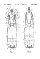
FIG. 1 is a diagrammatic axial section view of a device constituting a first embodiment of the invention, prior to the components being mixed together;
FIG. 2 shows a detail of the FIG. 1 embodiment;
FIG. 3 is a cross-section on section line III--III of FIG. 1;
FIG. 4 shows the FIG. 1 device after its components have been mixed together;
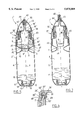
FIG. 5 is a diagrammatic axial section view of a device constituting a second embodiment of the invention;
FIG. 6 shows a detail of the FIG. 5 embodiment;
FIG. 7 shows the FIG. 5 device after its components have been mixed together; and
FIG. 8 is a diagrammatic axial section view of a device constituting a third embodiment of the invention.
FIGS. 1 to 4 show a device 1 constituting a first embodiment of the invention.
The device 1 comprises an elongate receptacle body 2 having a constriction 3 for establishing communication between a bottom compartment 4 and a top compartment 5.
In the embodiment described, the body 2 is generally circularly symmetrical about its longitudinal axis X.
Externally threaded necks 6 and 7 are respectively formed at the bottom and top axial ends of the body 2.
The body 2 is advantageously made by injection blow-molding using a plastics material that is chemically compatible with the components that are to be packaged. As an indication, if one of the components is thioglycolic acid, as is used in hairdressing for making permanent wave preparations, then the body 2 is advantageously made of PVC or is a multilayer structure of PE/EVOH/PE.
The necks 6 and 7 define openings that enable two components A and B that are to be stored separately until first use to be inserted into the body 2. In the particular embodiment described, the components A and B are both liquids.
A plug 8 is placed in the constriction 3 to separate the compartments 4 and 5 until first use, and it includes a sealing lip 9 that fits closely against the radially inner surface 10 of the constriction 3.
The inside diameter of the constriction 3 can be accurately controlled when the body 2 is made by injection blow-molding or by coextrusion blow-molding, thereby making it easier to obtain a sealing fit between the plug 8 and the constriction 3.
It will be observed that because of the relatively simple shape of the body 2, it is relatively easy to control its wall thickness, which is not the case for the bellows of the above-mentioned prior device. It is also difficult to make such bellows out of a multilayer material. The use of a multilayer material makes it possible to combine chemical resistance with mechanical strength while also making it possible to benefit from improved appearance, where appropriate.
The plug 8 is secured to a hollow drive rod 11 having a bottom portion with lateral openings via slots 12 that are angularly distributed around the longitudinal axis X. The drive rod 11 has a circularly cylindrical top portion 30.
After the bottom compartment 4 has been filled with the component B, it is closed by means of an end part 13 having a tubular skirt 14 shaped to screw onto the neck 6, and a sealing lip 15 shaped to fit closely against the inside of the neck 6. At its periphery, the part 13 has a skirt 16 shaped to extend the side wall of the body 2 downwards so as to improve the appearance of the device 1. The skirt 14 includes catches which co-operate with projections formed at the base of the neck 6 so as to prevent the end part 13 being unscrewed by a user.
A drive member 17 is rotatably mounted on the body 2 to enable the user to move the plug 8 so as to mix the components A and B together, in the manner described below.
The resulting mixture M can leave the body 2 via a dispenser endpiece 18 defining an outlet channel 19. The endpiece 18 has its bottom end connected via a transverse wall 26 to a coupling member 20 which is shaped to transform rotation of the drive member 17 into displacement of the plug 8 along the longitudinal axis X.
In the embodiment described, the endpiece 18 and the coupling member 20 are integrally formed with the wall 26 by molding a plastics material and they define an annular groove 21 for snap-fastening to the top end of the drive rod 11 which is thus secured to the coupling member 20.
More particularly, with reference to FIG. 2, the drive rod 11 is provided at its top end with an annular rim 22 defining a shoulder 23 against which there bears a radially inwardly projecting complementary shoulder 24 of the coupling member 20 once the rim 22 has been inserted into the groove 21. The annular rim 22 has a top radially outer surface 21 that tapers upwardly and a radially inner surface 27 that flares upwardly and that fits against an annular sealing rim 25 projecting downwards from the transverse wall 26.
The neck 7 is provided at its top end with an annular rim 29 projecting radially inwards, for bearing in sealed manner against the top portion 30 of the drive rod 11 when the plug 8 is moved upwards. When the plug 8 is in its initial position, the annular rim 29 is received in an annular groove 31 formed in the radially outer surface of the top portion 30 of the drive rod 11.
The coupling member 20 is in the form of a tubular skirt provided on its radially outer surface with axial ribs 32 and on its radially inner surface with threads shaped to engage on the thread of the neck 7. The ribs 32 are engaged in grooves of corresponding shape formed in the radially inner face of the inner tubular skirt 34 of the drive member 17, as shown more particularly in FIG. 3. The skirt 34 is connected to the inside face of a wall of the drive member constituting a cover 35, with the end surface thereof constituting a surface to be gripped by the user. The cover 35 is pierced at its top by an orifice 36 for passing the dispenser endpiece 18, and at its bottom it has a rim 37 that projects radially inwards and serves to hold the drive member 17 on the body 2 of the receptacle. The rim 37 bears against a shoulder 38 formed at the bottom end of the wall of the body 2 defining the side of the top compartment 5. The cover 35 bears axially at its free end 39 against the top end of the wall of the body 2 defining the side of the bottom compartment 4. Thus, the drive member 17 is free to rotate on the body 2 about the axis X, while being held axially relative to the body 2.
The device 1 is assembled as follows.
Firstly, the plug 8 is put into place inside the body 2 by being inserted through the opening of the neck 7. Sealing to separate the compartments 4 and 5 is advantageously tested at this stage of manufacture. Thereafter, the bottom compartment is filled with component B via the opening of the neck 6, and then the end part 13 is screwed thereon. Component A can then be inserted into the top compartment 5 through the opening of the neck 7, and pass into all of the top compartments via the side slots 12 in the drive rod 11. After the top compartment has been filled, the dispenser endpiece 18 is screwed together with the coupling member 20 onto the neck 7 until the annular rim 22 snaps into the groove 21.
After the grooves 33 have been put into register with the top ends of the ribs 32, the drive member 17 can then be lowered over the coupling member 20 and onto the top compartment of the body 2 merely by moving it downwards in translation until the annular rim 37 passes resiliently over the shoulder 38 and the cover 35 has come into abutment against the body 2.
It will be observed that while components A and B are being stored separately, the cap 40 does not emerge sufficiently through the orifice 36 for a user to be able to take hold of it.
It is thus impossible to unscrew the closure cap 40 in order to dispense component A, thereby avoiding any possibility of the user gaining access to unmixed component A.
It is thus possible, in complete safety, to use the device of the invention to package a component that is corrosive or that is an irritant, such as thioglycolic acid.
To use the device, the user turns the drive member 17 driving the coupling member 20 via the ribs 32 which are engaged in the grooves 33.
The thread on the neck 7 and the thread on the coupling member 20 are shaped so that rotating the coupling member 20 causes it to move upwards through a distance which is sufficient to displace the plug 8 from the constriction 3. While the coupling member 20 is moving upwards, the ribs 32 slide in the associated grooves 33 of the drive member 17. The coupling member 20 is accompanied in its axial displacement by the drive rod 11, and after the coupling member 20 has moved upwards through a stroke of sufficient length, the plug 18 releases the constriction 3 and allows component A contained in the top compartment 5 to flow into the bottom compartment 4 to be mixed with component B. It will be observed that displacement of the drive rod 11 and of the dispenser endpiece 18 increases the inside volume of the receptacle, with this being advantageous when mixing of components A and B is accompanied by an increase in the volume thereof, by heat being given off, or by gas being evolved, since this makes it possible to restrict the extra pressure generated in the receptacle when it is opened.
At the end of the rotary stroke of the drive member 17, the coupling member 20 has moved upwards through a distance which is sufficient for the closure cap 40 to become accessible to the user, who can then unscrew it to extract the mixture.
It is advantageous for the distributor endpiece to be opened by means of a screw cap since that makes it possible, where necessary, to release the residual excess pressure inside the receptacle in a progressive manner. Naturally, without going beyond the ambit of the invention, the cap 40 could be replaced by a snap-off tip formed integrally with the endpiece 18. Nevertheless, under such circumstances, it can be difficult to obtain an outlet orifice free from flash that could deflect the jet of substance leaving the orifice.
FIGS. 5 to 7 show a device 1' constituting a second embodiment of the invention. This device includes elements that are identical or functionally analogous to those of the preceding embodiment, which elements are given the same reference symbols and are not described in detail again.
The device 1' comprises a receptacle body 2' which differs from the body 2 mainly by the presence of bearing surfaces 41 formed on the radially outer surface of the wall defining the side of the top compartment 5. These bearing surfaces 41 have projections 42 at their bottom ends serving to retain the annular rim 37 of the drive member 17'. This drive member differs from the drive member 17 described above mainly by the presence on the outer surface of the cover 35' of ribs 43 which make it easier for the user to grip and by the presence, in the vicinity of the orifice 36, of tongues 44 which make a snapping sound when a collar 45 formed on the dispenser endpiece 18' goes past them, thereby informing the user that the drive member 17' has been turned far enough.
The tongues 44 preferably have respective teeth at their bottom ends capable of snapping resiliently past the collar 45 as it moves upwards, but preventing the dispenser endpiece 18' from moving back downwards. It is thus impossible, after first use, for the user to return the plug 8 into its initial position.
The collar 45 advantageously has openings (not shown) enabling a drop of substance running over the top end of the endpiece 18' to run into the drive member instead of running over its outside surface. This improves operating comfort.
The plug 8' is secured to a drive rod 11' whose top end has an annular rim 22' which is snapped into a groove 21'. The dispenser endpiece 18' and the coupling member 20' are integrally formed with a transverse wall 26' and together they form the above-mentioned groove 21'. The drive rod 11' has a bottom portion with openings in the form of lateral slots 12', and a circularly cylindrical top portion 30' extending axially from the top ends of the slots 12' to the rim 22'. Unlike the above-described rim 22, the rim 22' has a top face that is plane and substantially perpendicular to the longitudinal axis X, as shown in FIG. 6. This top face bears against the wall 26'. The annular rim 22' is retained in the groove 21' by snap-fastening engagement of a shoulder 24' analogous to the above-described shoulder 24. The wall 26' carries a sealing lip 25' on its bottom face which presses against the radially inner surface of the annular rim 22'.
The top portion 30' of the drive rod 11' does not have an annular groove 31 for receiving the annular rim 29, unlike the above-described embodiment.
The plug 8' is connected to the drive rod 11' by means of a shoulder 46' that comes to rest axially against a shoulder 47 formed by the constriction 3.
Preferably, the length of the drive rod 11' is selected so that it is compressed axially when the plug 8' rests via the shoulder 46 on the shoulder 47, and the annular rim 22' is snapped in the groove 21' and rests against the top end edge 48 of the neck 7.
The drive rod 11' is advantageously shaped so that under the effect of axial compression, its wall level with the lateral slots 12' tends to deform elastically radially inwards. By maintaining a small amount of axial compression in the drive rod 11' during storage, it is possible to further improve sealing of the closure of the compartment 5 during storage.
The device is filled, assembled, and used, in the same way as the above-described device 1.
FIG. 8 shows a device 1" in which the drive rod 11" is integrally molded with the coupling member 20".
The dispenser endpiece 18" is snap-fastened on an annular rib 50 that extends the drive rod 11" upwards.
Naturally, the invention is not limited to the embodiment described above.
In particular, the coupling member can be implemented differently, by replacing the slideway link between the coupling member and the drive member by a screw link and by replacing the screw link between the coupling member and the body of the receptacle by a slideway link.
Claims (20)
1. A device for separately packaging two components, for mixing them together, and for dispensing the resulting mixture, the device comprising a receptacle having two compartments, a removable plug for separating said compartments prior to first use, a dispenser endpiece defining an outlet channel initially closed by closure means, a rotary drive member suitable, in an initial position, for preventing the closure means being removed, and coupling means for transforming rotation of the drive member into action on the plug for the purpose of putting the two compartments into communication with each other, wherein said coupling means comprise a coupling member that is axially movable at the same time relative both to the two compartments of the receptacle and to the drive member.
2. A device according to claim 1, wherein said coupling means comprise a slideway link between the coupling member and one of the receptacle and the drive member.
3. A device according to claim 1, wherein said coupling member is in the form of a tubular skirt secured to the dispenser endpiece.
4. A device according to claim 3, wherein said tubular skirt co-operates by screw-engagement relative to the receptacle and by slideway link relative to the drive member.
5. A device according to claim 1, wherein said plug is integrally molded with a drive rod secured to said coupling member.
6. A device according to claim 5, wherein said drive rod is secured by snap-fastening to said coupling member, and wherein the dispenser endpiece is integrally molded with the coupling member.
7. A device according to claim 5, wherein the coupling member is integrally molded with the drive rod, and wherein the dispenser endpiece is secured to the drive rod by snap-fastening.
8. A device according to claim 5, wherein, when the drive member is in its initial position, the drive rod is axially compressed, and wherein the drive rod is shaped in such a manner as to be capable of deforming elastically under the effect of such compression.
9. A device according to claim 5, wherein the drive rod is hollow and has a circularly cylindrical top portion.
10. A device according to claim 1, wherein said receptacle comprises a body made as a single piece having two ends and having between these two ends a constriction serving as a seat for said plug prior to the components being mixed together.
11. A device according to claim 10, wherein said receptacle body is made by injection blow-molding.
12. A device according to claim 11, wherein said receptacle body is made by injection blow-molding using PVC.
13. A device according to claim 10, wherein said receptacle body is made by coextrusion blow-molding.
14. A device according to claim 13, wherein said receptacle body is made by molding coextruded PE/EVOH/PE material.
15. A device according to claim 10, wherein said plug has a shoulder shaped to bear axially against the constriction through which the two compartments communicate.
16. A device according to claim 1, wherein said receptacle has two ends and wherein these ends are both open prior to the receptacle being filled.
17. A device according to claim 1, wherein said drive member is externally in the form of a cover having a top and that snap-fastens onto the receptacle, wherein said cover is provided with a unique central aperture at its top through which said dispenser endpiece moves during rotation of the drive member, said closure means extending at least partly inside said drive member in said initial position and said closure means extending outside said drive member after the two compartments have been put into communication by the rotation of said drive member.
18. A device according to claim 17, wherein said cover snap-fastens on a rim formed at the end of the top compartment of the receptacle, adjacent to said constriction.
19. A device according to claim 17, including one portion in relief placed on the dispenser endpiece so that when said portion in relief sasses said aperture it clicks audibly, thereby informing a user that the dispenser endpiece has finished its stroke.
20. A device according to claim 1, wherein said closure means is formed by an internally threaded cap.
Applications Claiming Priority (2)
| Application Number | Priority Date | Filing Date | Title |
|---|---|---|---|
| FR9609820A FR2751941B1 (en) | 1996-08-02 | 1996-08-02 | DEVICE FOR THE SEPARATE PACKAGING OF TWO COMPONENTS, THEIR MIXING AND THE DISTRIBUTION OF THE MIXTURE THUS OBTAINED |
| FR9609820 | 1996-08-02 |
Publications (1)
| Publication Number | Publication Date |
|---|---|
| US5875889A true US5875889A (en) | 1999-03-02 |
Family
ID=9494791
Family Applications (1)
| Application Number | Title | Priority Date | Filing Date |
|---|---|---|---|
| US08/897,671 Expired - Fee Related US5875889A (en) | 1996-08-02 | 1997-07-21 | Device for separately packaging two components, for mixing them together and for dispensing the resulting mixture |
Country Status (7)
| Country | Link |
|---|---|
| US (1) | US5875889A (en) |
| EP (1) | EP0822148A1 (en) |
| JP (1) | JPH1081337A (en) |
| AR (1) | AR008415A1 (en) |
| BR (1) | BR9704242A (en) |
| FR (1) | FR2751941B1 (en) |
| MX (1) | MX9705762A (en) |
Cited By (35)
| Publication number | Priority date | Publication date | Assignee | Title |
|---|---|---|---|---|
| US5992693A (en) * | 1997-07-08 | 1999-11-30 | L'oreal | Device for packaging two components |
| US6021892A (en) * | 1997-06-20 | 2000-02-08 | L'oreal | Device for packaging a product comprising constituents which must be stored separately and mixed just before use of the product |
| US6182822B1 (en) * | 1997-08-29 | 2001-02-06 | L'oreal | Assembly of two elements mounted to rotate freely one with respect to the other irreversibly |
| US6293433B1 (en) * | 1999-09-22 | 2001-09-25 | L'oreal | Dispensing device and method for separately storing components and mixing the components |
| US20030024830A1 (en) * | 2001-08-06 | 2003-02-06 | Igal Sharon | Multi-compartment container assembly system |
| US20030105448A1 (en) * | 2001-12-03 | 2003-06-05 | Yasuyuki Shiraishi | Infusion vessel |
| US20030150748A1 (en) * | 2000-05-03 | 2003-08-14 | Crawley Alan Mark | Multi-component mixing |
| US20030158537A1 (en) * | 2002-02-21 | 2003-08-21 | Taisei Kako Co., Ltd. | Infusion vessel |
| US6705491B1 (en) | 2002-09-12 | 2004-03-16 | Eric K. Lizerbram | Self contained additive reservoirs for use with beverage containers |
| US20040089563A1 (en) * | 2002-11-12 | 2004-05-13 | Igal Sharon | Multi-compartment container assembly system |
| EP1439133A1 (en) * | 2003-01-17 | 2004-07-21 | Veltek Associates Inc. | Mixing and dispensing apparatus |
| US20040155061A1 (en) * | 2003-02-10 | 2004-08-12 | Donna Roth | Flavoring component holding dispenser for use with consumable beverages |
| US20040238566A1 (en) * | 2003-01-17 | 2004-12-02 | Stank Robert E. | Mixing and dispensing apparatus |
| US20040261872A1 (en) * | 2001-12-06 | 2004-12-30 | Bernard Mermet | Flowrate control device, in particular for medical use |
| US20050075613A1 (en) * | 2003-06-27 | 2005-04-07 | Mitsuru Hasegawa | Displaceable-plug-containing filling/discharging port and medical container having the same |
| US20050163651A1 (en) * | 2004-01-12 | 2005-07-28 | Vellutato Arthur L.Sr. | Method for mixing and dispensing |
| US20060198798A1 (en) * | 2005-02-25 | 2006-09-07 | Tichy Daryl J | Aqueous disinfectants and sterilants for skin and mucosal application |
| US20070166269A1 (en) * | 2005-12-01 | 2007-07-19 | L'oreal | Cosmetic composition containing a statistical polymer with a linear chain of ethylenic nature |
| US20080000931A1 (en) * | 2005-02-25 | 2008-01-03 | Tichy Daryl J | Devices, systems, and methods for dispensing disinfectant solutions |
| US20090004289A1 (en) * | 2005-02-25 | 2009-01-01 | Solutions Biomed, Llc | Method of disinfecting and providing residual kill at a surface |
| US20090053323A1 (en) * | 2005-02-25 | 2009-02-26 | Tichy Dary J | Aqueous disinfectants and sterilants including transition metals |
| US20090211927A1 (en) * | 2008-02-21 | 2009-08-27 | Wu Kuo Cheng | Container structure for contain different beverages |
| US20090232860A1 (en) * | 2007-08-30 | 2009-09-17 | Larson Brian G | Colloidal metal-containing skin sanitizer |
| US20090277929A1 (en) * | 2008-03-14 | 2009-11-12 | Larson Brian G | Multi-Chamber Container System for Storing and Mixing Fluids |
| US20090308889A1 (en) * | 2008-06-11 | 2009-12-17 | Frank Lindsay | Container system |
| US20100116346A1 (en) * | 2008-11-12 | 2010-05-13 | Larson Brian G | Multi-chamber container system for storing and mixing liquids |
| US20100120913A1 (en) * | 2008-11-12 | 2010-05-13 | Larson Brian G | Resin catalyzed and stabilized peracid compositions and associated methods |
| US20100143496A1 (en) * | 2008-11-12 | 2010-06-10 | Larson Brian G | Two-part disinfectant system and related methods |
| US20100163442A1 (en) * | 2005-12-12 | 2010-07-01 | Lee Jeong-Min | Cap assembly having storage chamber for secondary material with inseparable working member |
| US20100187257A1 (en) * | 2003-02-10 | 2010-07-29 | Donna Roth | Flavoring Component Holding Dispenser for use with Consumable Beverages |
| US8523017B2 (en) | 2011-09-22 | 2013-09-03 | Veltek Associates, Inc. | Mixing and dispensing apparatus |
| GB2515049A (en) * | 2013-06-11 | 2014-12-17 | Richard Lloyd Emmett | A Drink Mixing Device |
| US20150274398A1 (en) * | 2012-11-07 | 2015-10-01 | Hana Co., Ltd | Cosmetic container with different types of mixed materials |
| US20180354703A1 (en) * | 2017-06-12 | 2018-12-13 | Bio-Techne Corporation | Dual chamber storage device |
| WO2021015467A1 (en) * | 2019-07-23 | 2021-01-28 | 강성일 | Two-liquid container |
Families Citing this family (10)
| Publication number | Priority date | Publication date | Assignee | Title |
|---|---|---|---|---|
| FR2767680B1 (en) * | 1997-09-02 | 1999-12-03 | Seb Sa | REMOVABLE BOTTLE |
| DE19846836A1 (en) * | 1998-10-12 | 2000-04-20 | Goldwell Gmbh | Two-chamber packaging |
| JP4721208B2 (en) * | 2001-04-27 | 2011-07-13 | 株式会社吉野工業所 | Mixing container |
| US20080142032A1 (en) * | 2006-12-13 | 2008-06-19 | Marc Anthony Venture Corporation | Hair dye touch-up dispenser and method of using the same |
| WO2009096803A1 (en) * | 2008-01-29 | 2009-08-06 | Skvortsov, Igor Victorovich | 'expromt' bottle |
| JP5210961B2 (en) * | 2009-04-30 | 2013-06-12 | 株式会社吉野工業所 | Mixing container |
| CN102673896A (en) * | 2011-03-11 | 2012-09-19 | 吴振文 | Container |
| CN103029913A (en) * | 2011-09-30 | 2013-04-10 | 汤维哲 | Double-dye container |
| FR2993541A1 (en) * | 2012-07-17 | 2014-01-24 | Thierry Joseph Paul Laurent | Watertight closed container i.e. bottle, for packaging e.g. liquids used for food, has watertight separation wall formed at inner side of central body and creating independent and joint compartments for storage of identical liquids |
| JP7174342B2 (en) * | 2018-03-29 | 2022-11-17 | 大日本印刷株式会社 | Container and container with inner stopper |
Citations (13)
| Publication number | Priority date | Publication date | Assignee | Title |
|---|---|---|---|---|
| FR1509145A (en) * | 1966-11-30 | 1968-01-12 | Int Verigoud Soc | Double stopper for bottle with two superimposed compartments |
| US3856138A (en) * | 1973-05-31 | 1974-12-24 | Shionogi & Co | Compartmentalized container |
| FR2506726A1 (en) * | 1981-06-01 | 1982-12-03 | Oreal | Detachable diaphragm design for a twin chamber container - to allow use of plastics materials with higher tear resistance than polyethylene |
| FR2599006A1 (en) * | 1986-05-26 | 1987-11-27 | Oreal | Assembly allowing the separate packaging of products and the simultaneous dispensing of them after placing them in contact |
| US4936446A (en) * | 1988-03-02 | 1990-06-26 | Laboratoires Merck, Sharp & Dohme-Chibret | Packaging and dispensing system for packaging two ingredients separately and mixing them extemporaneously at the time of first use, and method of assembling same |
| DE4006193A1 (en) * | 1990-02-28 | 1991-08-29 | Benno Becker | Screw glass jar with lid - incorporates removable base for easier recycling and cleaning |
| US5088627A (en) * | 1990-07-25 | 1992-02-18 | Wheaton Industries | Multi-chamber package for mixing and dispensing |
| FR2687567A1 (en) * | 1992-02-20 | 1993-08-27 | Merck Sharp & Dohme | Packaging and dispensing assembly making it possible separately to package two liquid components, and to mix them extemporaneously on the first use, and method of manufacture of such as assembly |
| US5277303A (en) * | 1991-08-16 | 1994-01-11 | L'oreal | Two bottle packaging allowing separate storage and mixing for use of two products, particularly liquids |
| EP0588667A2 (en) * | 1992-09-18 | 1994-03-23 | W.R. Grace & Co.-Conn. | Moisture barrier film |
| US5417321A (en) * | 1993-08-04 | 1995-05-23 | Goldwell Ag | Two-compartment container |
| FR2729372A1 (en) * | 1995-01-12 | 1996-07-19 | Defi International | Packaging for separate components requiring to be mixed before dispensing |
| US5613623A (en) * | 1994-08-09 | 1997-03-25 | Wella Aktiengesellschaft | Two-chamber container |
-
1996
- 1996-08-02 FR FR9609820A patent/FR2751941B1/en not_active Expired - Fee Related
-
1997
- 1997-07-21 US US08/897,671 patent/US5875889A/en not_active Expired - Fee Related
- 1997-07-30 MX MX9705762A patent/MX9705762A/en not_active IP Right Cessation
- 1997-08-01 AR ARP970103489A patent/AR008415A1/en unknown
- 1997-08-01 BR BR9704242A patent/BR9704242A/en not_active Application Discontinuation
- 1997-08-01 EP EP97401860A patent/EP0822148A1/en not_active Withdrawn
- 1997-08-04 JP JP9208912A patent/JPH1081337A/en active Pending
Patent Citations (13)
| Publication number | Priority date | Publication date | Assignee | Title |
|---|---|---|---|---|
| FR1509145A (en) * | 1966-11-30 | 1968-01-12 | Int Verigoud Soc | Double stopper for bottle with two superimposed compartments |
| US3856138A (en) * | 1973-05-31 | 1974-12-24 | Shionogi & Co | Compartmentalized container |
| FR2506726A1 (en) * | 1981-06-01 | 1982-12-03 | Oreal | Detachable diaphragm design for a twin chamber container - to allow use of plastics materials with higher tear resistance than polyethylene |
| FR2599006A1 (en) * | 1986-05-26 | 1987-11-27 | Oreal | Assembly allowing the separate packaging of products and the simultaneous dispensing of them after placing them in contact |
| US4936446A (en) * | 1988-03-02 | 1990-06-26 | Laboratoires Merck, Sharp & Dohme-Chibret | Packaging and dispensing system for packaging two ingredients separately and mixing them extemporaneously at the time of first use, and method of assembling same |
| DE4006193A1 (en) * | 1990-02-28 | 1991-08-29 | Benno Becker | Screw glass jar with lid - incorporates removable base for easier recycling and cleaning |
| US5088627A (en) * | 1990-07-25 | 1992-02-18 | Wheaton Industries | Multi-chamber package for mixing and dispensing |
| US5277303A (en) * | 1991-08-16 | 1994-01-11 | L'oreal | Two bottle packaging allowing separate storage and mixing for use of two products, particularly liquids |
| FR2687567A1 (en) * | 1992-02-20 | 1993-08-27 | Merck Sharp & Dohme | Packaging and dispensing assembly making it possible separately to package two liquid components, and to mix them extemporaneously on the first use, and method of manufacture of such as assembly |
| EP0588667A2 (en) * | 1992-09-18 | 1994-03-23 | W.R. Grace & Co.-Conn. | Moisture barrier film |
| US5417321A (en) * | 1993-08-04 | 1995-05-23 | Goldwell Ag | Two-compartment container |
| US5613623A (en) * | 1994-08-09 | 1997-03-25 | Wella Aktiengesellschaft | Two-chamber container |
| FR2729372A1 (en) * | 1995-01-12 | 1996-07-19 | Defi International | Packaging for separate components requiring to be mixed before dispensing |
Cited By (78)
| Publication number | Priority date | Publication date | Assignee | Title |
|---|---|---|---|---|
| US6021892A (en) * | 1997-06-20 | 2000-02-08 | L'oreal | Device for packaging a product comprising constituents which must be stored separately and mixed just before use of the product |
| US5992693A (en) * | 1997-07-08 | 1999-11-30 | L'oreal | Device for packaging two components |
| US6182822B1 (en) * | 1997-08-29 | 2001-02-06 | L'oreal | Assembly of two elements mounted to rotate freely one with respect to the other irreversibly |
| US6293433B1 (en) * | 1999-09-22 | 2001-09-25 | L'oreal | Dispensing device and method for separately storing components and mixing the components |
| US20030150748A1 (en) * | 2000-05-03 | 2003-08-14 | Crawley Alan Mark | Multi-component mixing |
| US20060272963A1 (en) * | 2001-08-06 | 2006-12-07 | Igal Sharon | Multi-compartment container assembly system |
| US20030024830A1 (en) * | 2001-08-06 | 2003-02-06 | Igal Sharon | Multi-compartment container assembly system |
| US7083043B2 (en) * | 2001-08-06 | 2006-08-01 | Uc Technologies & Engineering Ltd. | Multi-compartment container assembly system |
| US7523822B2 (en) * | 2001-08-06 | 2009-04-28 | Igal Sharon | Multi-compartment container assembly system |
| GB2384769A (en) * | 2001-12-03 | 2003-08-06 | Taisei Kako Co | An infusion vessel for the separate storage of two components and for mixing them |
| GB2384769B (en) * | 2001-12-03 | 2004-01-21 | Taisei Kako Co | Infusion vessel |
| US7404814B2 (en) * | 2001-12-03 | 2008-07-29 | Taisei Kako Co., Ltd. | Infusion vessel |
| US20030105448A1 (en) * | 2001-12-03 | 2003-06-05 | Yasuyuki Shiraishi | Infusion vessel |
| US20040261872A1 (en) * | 2001-12-06 | 2004-12-30 | Bernard Mermet | Flowrate control device, in particular for medical use |
| US7028927B2 (en) * | 2001-12-06 | 2006-04-18 | Sobem | Flowrate control device, in particular for medical use |
| US7115117B2 (en) * | 2002-02-21 | 2006-10-03 | Taisei Kako Co., Ltd. | Infusion vessel |
| US20030158537A1 (en) * | 2002-02-21 | 2003-08-21 | Taisei Kako Co., Ltd. | Infusion vessel |
| US6705490B1 (en) | 2002-09-12 | 2004-03-16 | Eric K. Lizerbram | Self contained additive reservoirs for use with beverage containers |
| US6705491B1 (en) | 2002-09-12 | 2004-03-16 | Eric K. Lizerbram | Self contained additive reservoirs for use with beverage containers |
| CN100363238C (en) * | 2002-11-12 | 2008-01-23 | M.L.I.S.工程公司 | Multi-compartment container assembly system |
| US6959807B2 (en) * | 2002-11-12 | 2005-11-01 | M.L.I.S. Projects Ltd. | Multi-compartment container assembly system |
| US20040089563A1 (en) * | 2002-11-12 | 2004-05-13 | Igal Sharon | Multi-compartment container assembly system |
| US6851580B2 (en) | 2003-01-17 | 2005-02-08 | Veltek Associates, Inc. | Mixing and dispensing apparatus |
| US20040140321A1 (en) * | 2003-01-17 | 2004-07-22 | Stank Robert E. | Mixing and dispensing apparatus |
| EP1439133A1 (en) * | 2003-01-17 | 2004-07-21 | Veltek Associates Inc. | Mixing and dispensing apparatus |
| US7066354B2 (en) | 2003-01-17 | 2006-06-27 | Stank Robert E | Mixing and dispensing apparatus |
| US20040238566A1 (en) * | 2003-01-17 | 2004-12-02 | Stank Robert E. | Mixing and dispensing apparatus |
| US8499971B2 (en) | 2003-02-10 | 2013-08-06 | Cool Gear International, Llc | Flavoring component holding dispenser for use with consumable beverages |
| US6959839B2 (en) * | 2003-02-10 | 2005-11-01 | Donna Roth | Flavoring component holding dispenser for use with consumable beverages |
| US8011534B2 (en) | 2003-02-10 | 2011-09-06 | Cool Gear International, Llc | Flavoring component holding dispenser for use with consumable beverages |
| US7909210B2 (en) | 2003-02-10 | 2011-03-22 | Cool Gear International, Llc | Flavoring component holding dispenser for use with consumable beverages |
| US7306117B2 (en) | 2003-02-10 | 2007-12-11 | Donna Roth | Flavoring component holding dispenser for use with consumable beverages |
| US20100187257A1 (en) * | 2003-02-10 | 2010-07-29 | Donna Roth | Flavoring Component Holding Dispenser for use with Consumable Beverages |
| US20130327788A1 (en) * | 2003-02-10 | 2013-12-12 | Cool Gear International, Llc | Flavoring component holding dispenser for use with consumable beverages |
| US20080054001A1 (en) * | 2003-02-10 | 2008-03-06 | Donna Roth | Flavoring Component Holding Dispenser For Use With Consumable Beverages |
| US20040155061A1 (en) * | 2003-02-10 | 2004-08-12 | Donna Roth | Flavoring component holding dispenser for use with consumable beverages |
| US20050075613A1 (en) * | 2003-06-27 | 2005-04-07 | Mitsuru Hasegawa | Displaceable-plug-containing filling/discharging port and medical container having the same |
| US7207970B2 (en) * | 2003-06-27 | 2007-04-24 | Nipro Corporation | Displaceable-plug-containing filling/discharging port and medical container having the same |
| US10729795B2 (en) | 2004-01-12 | 2020-08-04 | Veltek Associates, Inc. | Method for mixing and dispensing |
| US20050163651A1 (en) * | 2004-01-12 | 2005-07-28 | Vellutato Arthur L.Sr. | Method for mixing and dispensing |
| US20090053323A1 (en) * | 2005-02-25 | 2009-02-26 | Tichy Dary J | Aqueous disinfectants and sterilants including transition metals |
| US8802061B2 (en) | 2005-02-25 | 2014-08-12 | Solutions Biomed, Llc | Aqueous disinfectants and sterilants for skin and mucosal application |
| US7534756B2 (en) | 2005-02-25 | 2009-05-19 | Solutions Biomed, Llc | Devices, systems, and methods for dispensing disinfectant solutions comprising a peroxygen and transition metal |
| US7935667B2 (en) | 2005-02-25 | 2011-05-03 | Solutions Biomed, Llc | Aqueous disinfectants and sterilants including colloidal transition metals |
| US20060198798A1 (en) * | 2005-02-25 | 2006-09-07 | Tichy Daryl J | Aqueous disinfectants and sterilants for skin and mucosal application |
| US8084411B2 (en) | 2005-02-25 | 2011-12-27 | Solutions Biomed, Llc | Method of disinfecting and providing residual kill at a surface |
| US8071525B2 (en) | 2005-02-25 | 2011-12-06 | Solutions Biomed, Llc | Aqueous disinfectants and sterilants including transition metals |
| US20090004289A1 (en) * | 2005-02-25 | 2009-01-01 | Solutions Biomed, Llc | Method of disinfecting and providing residual kill at a surface |
| US20080000931A1 (en) * | 2005-02-25 | 2008-01-03 | Tichy Daryl J | Devices, systems, and methods for dispensing disinfectant solutions |
| US20070166269A1 (en) * | 2005-12-01 | 2007-07-19 | L'oreal | Cosmetic composition containing a statistical polymer with a linear chain of ethylenic nature |
| US8485353B2 (en) * | 2005-12-12 | 2013-07-16 | Jeong-min Lee | Cap assembly having storage chamber for secondary material with inseparable working member |
| US20100163442A1 (en) * | 2005-12-12 | 2010-07-01 | Lee Jeong-Min | Cap assembly having storage chamber for secondary material with inseparable working member |
| US8991596B2 (en) | 2005-12-12 | 2015-03-31 | Jeong-min Lee | Cap assembly having storage chamber for secondary material with inseparable working member |
| US20090232860A1 (en) * | 2007-08-30 | 2009-09-17 | Larson Brian G | Colloidal metal-containing skin sanitizer |
| US20090211927A1 (en) * | 2008-02-21 | 2009-08-27 | Wu Kuo Cheng | Container structure for contain different beverages |
| US8464910B2 (en) | 2008-03-14 | 2013-06-18 | Solutions Biomed, Llc | Multi-chamber container system for storing and mixing fluids |
| US20090277929A1 (en) * | 2008-03-14 | 2009-11-12 | Larson Brian G | Multi-Chamber Container System for Storing and Mixing Fluids |
| US20090308889A1 (en) * | 2008-06-11 | 2009-12-17 | Frank Lindsay | Container system |
| US20100116346A1 (en) * | 2008-11-12 | 2010-05-13 | Larson Brian G | Multi-chamber container system for storing and mixing liquids |
| US8716339B2 (en) | 2008-11-12 | 2014-05-06 | Solutions Biomed, Llc | Two-part disinfectant system and related methods |
| US8789716B2 (en) | 2008-11-12 | 2014-07-29 | Solutions Biomed, Llc | Multi-chamber container system for storing and mixing liquids |
| US20100120913A1 (en) * | 2008-11-12 | 2010-05-13 | Larson Brian G | Resin catalyzed and stabilized peracid compositions and associated methods |
| US20100143496A1 (en) * | 2008-11-12 | 2010-06-10 | Larson Brian G | Two-part disinfectant system and related methods |
| US8987331B2 (en) | 2008-11-12 | 2015-03-24 | Solutions Biomed, Llc | Two-part disinfectant system and related methods |
| US8523017B2 (en) | 2011-09-22 | 2013-09-03 | Veltek Associates, Inc. | Mixing and dispensing apparatus |
| US9764342B2 (en) | 2011-09-22 | 2017-09-19 | Veltek Associates, Inc | Mixing and dispensing apparatus |
| US10744523B2 (en) | 2011-09-22 | 2020-08-18 | Veltek Associates, Inc. | Mixing and dispensing apparatus |
| US10335812B2 (en) | 2011-09-22 | 2019-07-02 | Veltek Associates, Inc. | Mixing and dispensing apparatus |
| US9108208B2 (en) | 2011-09-22 | 2015-08-18 | Veltek Associates. Inc. | Mixing and dispensing apparatus |
| US9598220B2 (en) * | 2012-11-07 | 2017-03-21 | Amorepacific Corporation | Cosmetic container with different types of mixed materials |
| US20150274398A1 (en) * | 2012-11-07 | 2015-10-01 | Hana Co., Ltd | Cosmetic container with different types of mixed materials |
| GB2515049B (en) * | 2013-06-11 | 2015-12-16 | Richard Lloyd Emmett | A Drink Mixing Device |
| GB2515049A (en) * | 2013-06-11 | 2014-12-17 | Richard Lloyd Emmett | A Drink Mixing Device |
| US20180354703A1 (en) * | 2017-06-12 | 2018-12-13 | Bio-Techne Corporation | Dual chamber storage device |
| US10640275B2 (en) * | 2017-06-12 | 2020-05-05 | Bio-Techne Corportion | Dual chamber storage device |
| US10640276B2 (en) | 2017-06-12 | 2020-05-05 | Bio-Techne Corporation | Dual chamber storage device |
| WO2021015467A1 (en) * | 2019-07-23 | 2021-01-28 | 강성일 | Two-liquid container |
| CN114126981A (en) * | 2019-07-23 | 2022-03-01 | 姜成一 | Double-liquid container |
Also Published As
| Publication number | Publication date |
|---|---|
| AR008415A1 (en) | 2000-01-19 |
| EP0822148A1 (en) | 1998-02-04 |
| MX9705762A (en) | 1998-02-28 |
| FR2751941B1 (en) | 1998-09-11 |
| JPH1081337A (en) | 1998-03-31 |
| FR2751941A1 (en) | 1998-02-06 |
| BR9704242A (en) | 1998-11-03 |
Similar Documents
| Publication | Publication Date | Title |
|---|---|---|
| US5875889A (en) | Device for separately packaging two components, for mixing them together and for dispensing the resulting mixture | |
| US5875888A (en) | Device for separately storing two components, for mixing them, and for dispensing the mixture | |
| US5088627A (en) | Multi-chamber package for mixing and dispensing | |
| US7866465B2 (en) | Multi-compartment storage and mixing vessel | |
| US6609634B2 (en) | Dispensing device and methods | |
| US5992693A (en) | Device for packaging two components | |
| US5060791A (en) | Two-chamber container | |
| US3155281A (en) | Container | |
| JP3312734B2 (en) | Multi-compartment distributor for storing and mixing contents. | |
| MXPA97005762A (en) | Device to pack separately two components, its mixture and the distribution of the mixture asi obtain | |
| US6244433B1 (en) | Device for storing three components, for mixing them, and for dispensing the mixture obtained thereby | |
| US6543645B2 (en) | Device and method for sampling and mixing products | |
| JP6728371B2 (en) | Filling assembly for producing a packaging dispenser for two contents | |
| MXPA97005764A (en) | Devices for storing separately two components, its mixture and the distribucc | |
| US7690534B2 (en) | Device for placing two products in contact | |
| US6923347B2 (en) | Assembly for packaging a product, especially a cosmetic product | |
| US6293433B1 (en) | Dispensing device and method for separately storing components and mixing the components | |
| CN110536843B (en) | Packaging and dispensing assembly with return air for fluid products | |
| CN108495574B (en) | Packaging and dispensing device for dual contents | |
| US5988453A (en) | Pressurized device | |
| CN116157337B (en) | Container-closure system | |
| US6920904B2 (en) | Device for packaging and dispensing at least two products | |
| CN109415145A (en) | Container-closure with the mechanism introduced the additive into the liquid in container | |
| US5316058A (en) | Container having a self-opening pouring spout | |
| CN113423652A (en) | Device for packaging two products separately |
Legal Events
| Date | Code | Title | Description |
|---|---|---|---|
| FEPP | Fee payment procedure |
Free format text: PAYOR NUMBER ASSIGNED (ORIGINAL EVENT CODE: ASPN); ENTITY STATUS OF PATENT OWNER: LARGE ENTITY |
|
| AS | Assignment |
Owner name: L'OREAL, FRANCE Free format text: ASSIGNMENT OF ASSIGNORS INTEREST;ASSIGNOR:ALBISETTI, NICOLAS;REEL/FRAME:008913/0979 Effective date: 19970626 |
|
| FPAY | Fee payment |
Year of fee payment: 4 |
|
| REMI | Maintenance fee reminder mailed | ||
| LAPS | Lapse for failure to pay maintenance fees | ||
| STCH | Information on status: patent discontinuation |
Free format text: PATENT EXPIRED DUE TO NONPAYMENT OF MAINTENANCE FEES UNDER 37 CFR 1.362 |
|
| FP | Lapsed due to failure to pay maintenance fee |
Effective date: 20070302 |