US5914027A - Thermo-mechanical cracking and hydrogenation - Google Patents
Thermo-mechanical cracking and hydrogenation Download PDFInfo
- Publication number
- US5914027A US5914027A US08/814,333 US81433397A US5914027A US 5914027 A US5914027 A US 5914027A US 81433397 A US81433397 A US 81433397A US 5914027 A US5914027 A US 5914027A
- Authority
- US
- United States
- Prior art keywords
- cracking
- reactor
- mechanical
- hydrogenation
- thermo
- Prior art date
- Legal status (The legal status is an assumption and is not a legal conclusion. Google has not performed a legal analysis and makes no representation as to the accuracy of the status listed.)
- Expired - Lifetime
Links
Images


Classifications
-
- B—PERFORMING OPERATIONS; TRANSPORTING
- B01—PHYSICAL OR CHEMICAL PROCESSES OR APPARATUS IN GENERAL
- B01J—CHEMICAL OR PHYSICAL PROCESSES, e.g. CATALYSIS OR COLLOID CHEMISTRY; THEIR RELEVANT APPARATUS
- B01J8/00—Chemical or physical processes in general, conducted in the presence of fluids and solid particles; Apparatus for such processes
- B01J8/08—Chemical or physical processes in general, conducted in the presence of fluids and solid particles; Apparatus for such processes with moving particles
- B01J8/10—Chemical or physical processes in general, conducted in the presence of fluids and solid particles; Apparatus for such processes with moving particles moved by stirrers or by rotary drums or rotary receptacles or endless belts
-
- B—PERFORMING OPERATIONS; TRANSPORTING
- B01—PHYSICAL OR CHEMICAL PROCESSES OR APPARATUS IN GENERAL
- B01J—CHEMICAL OR PHYSICAL PROCESSES, e.g. CATALYSIS OR COLLOID CHEMISTRY; THEIR RELEVANT APPARATUS
- B01J19/00—Chemical, physical or physico-chemical processes in general; Their relevant apparatus
- B01J19/008—Processes for carrying out reactions under cavitation conditions
-
- B—PERFORMING OPERATIONS; TRANSPORTING
- B01—PHYSICAL OR CHEMICAL PROCESSES OR APPARATUS IN GENERAL
- B01J—CHEMICAL OR PHYSICAL PROCESSES, e.g. CATALYSIS OR COLLOID CHEMISTRY; THEIR RELEVANT APPARATUS
- B01J8/00—Chemical or physical processes in general, conducted in the presence of fluids and solid particles; Apparatus for such processes
- B01J8/16—Chemical or physical processes in general, conducted in the presence of fluids and solid particles; Apparatus for such processes with particles being subjected to vibrations or pulsations
-
- C—CHEMISTRY; METALLURGY
- C10—PETROLEUM, GAS OR COKE INDUSTRIES; TECHNICAL GASES CONTAINING CARBON MONOXIDE; FUELS; LUBRICANTS; PEAT
- C10G—CRACKING HYDROCARBON OILS; PRODUCTION OF LIQUID HYDROCARBON MIXTURES, e.g. BY DESTRUCTIVE HYDROGENATION, OLIGOMERISATION, POLYMERISATION; RECOVERY OF HYDROCARBON OILS FROM OIL-SHALE, OIL-SAND, OR GASES; REFINING MIXTURES MAINLY CONSISTING OF HYDROCARBONS; REFORMING OF NAPHTHA; MINERAL WAXES
- C10G1/00—Production of liquid hydrocarbon mixtures from oil-shale, oil-sand, or non-melting solid carbonaceous or similar materials, e.g. wood, coal
- C10G1/02—Production of liquid hydrocarbon mixtures from oil-shale, oil-sand, or non-melting solid carbonaceous or similar materials, e.g. wood, coal by distillation
-
- C—CHEMISTRY; METALLURGY
- C10—PETROLEUM, GAS OR COKE INDUSTRIES; TECHNICAL GASES CONTAINING CARBON MONOXIDE; FUELS; LUBRICANTS; PEAT
- C10G—CRACKING HYDROCARBON OILS; PRODUCTION OF LIQUID HYDROCARBON MIXTURES, e.g. BY DESTRUCTIVE HYDROGENATION, OLIGOMERISATION, POLYMERISATION; RECOVERY OF HYDROCARBON OILS FROM OIL-SHALE, OIL-SAND, OR GASES; REFINING MIXTURES MAINLY CONSISTING OF HYDROCARBONS; REFORMING OF NAPHTHA; MINERAL WAXES
- C10G1/00—Production of liquid hydrocarbon mixtures from oil-shale, oil-sand, or non-melting solid carbonaceous or similar materials, e.g. wood, coal
- C10G1/06—Production of liquid hydrocarbon mixtures from oil-shale, oil-sand, or non-melting solid carbonaceous or similar materials, e.g. wood, coal by destructive hydrogenation
Definitions
- the energy to break the molecular bonds in refinery cracking processes is supplied by thermal motion of the molecules subjected to heating and excess pressure in addition to the effects of added catalyst(s).
- the present invention describes a method of achieving high efficiency cracking of carbonaceous material at low temperatures and pressure and with use of less energy than any known methods.
- the carbonaceous material consists of high molecular weight hydrocarbons, petroleum residues, plastic, rubber in either liquid or solid state.
- the principle of the process is to treat the carbonaceous material in a mechanical established hot fluidized bed containing water and solids to achieve cracking in order to recover valuable oil products from:
- the mechanically fluidized bed generated in a process chamber can be established by different means.
- One practical means is to apply a hammer-mill construction.
- a second way is to use a ball-mill construction.
- the hydrodynamic behavior in the new process is a complex subject. It takes into consideration bed behavior, the mechanics of bubbles and flow models.
- bed behavior includes observations about pressure fluctuations, flow regimes, incipient fluidization, phase holdups and solids entrainment, solids wettability and surface tension effects and overall bed rheology.
- the hydrodynamics, chemical reactor kinetics and final product composition, heat and mass transfer are strongly influenced by external means such as mechanical agitation which again are closely linked to operational aspects and mechanical motion of the bed.
- thermo-mechanical process Being a thermo-mechanical process, it is unique to other thermodynamic processes in several respects:
- the fluidized bed condition of the mass in the reactor acts as a very efficient heat transfer fluid.
- the energy requirement of the process us very favorable compared to other processes as no external heating is required.
- the heat is applied in-situ by abrasion and agitation of the treated material.
- a major advantage of the new technology is the reduction of high-boiling oil feedstock materials to make products in the middle distillate range, diesel oil or light gas oil of high economic value.
- All high molecular weight material including asphaltenes and resins are subject to cracking to lower molecular weight compounds. Only trace amounts of residue or coke is being formed in the process under steady-state conditions.
- the fluidized bed condition of the mass in the reactor under steady state conditions acts as a diluent to inhibit bimolecular addition for condensation reactions relative to uni-molecular cracking reactions.
- the aliphatic fraction of the products is characterized by a marked increase of cyclic alkanes compared with the corresponding feedstock. This may in part be due to hydrogenation of aromatics in the original feedstock as mentioned above.
- the nitrogen removal is estimated to approx. 85%.
- Oxygen is estimated to close to 90%. Most of the functional groups in this category contains substituents of--OH and --COOH type that will not survive the reactor conditions in the process.
- the thermic cracking leads to en efficient removal of metals from the original feedstock with a decline in Ni of 88% and V of >95%.
- Non-condensable gases amounting to ⁇ 5% of the total mass of the original feedstock for many types of feedstocks (exceptions are coke and oil-shale) under steady state conditions consist mainly of CO 2 , CO, N 2 , CH 4 , H 2 , O 2 and low concentrations of ethane and propane. Only trace amounts of H 2 S, SO 2 , RSR, RSSR, NH 3 and NO x have been observed. Minute amount of organic sulphides (RSR) and organic disulphides (RSSR) have observed.
- transient cavitation bubbles of high pressure (>300 bars) and temperature (>5000 E) is due to the hydrodynamic conditions in the reaction chamber.
- Hydrodynamic cavitation can affect a liquid through two possible avenues. The first is that the liquid is disrupted by inhomogeneous presence of the bubbles. The second avenue through which cavitation affects a fluid is bubble dynamics.
- the main interest in cavitation bubble dynamics arises from the destructive action due to the collapse of bubbles in liquids near solid boundaries.
- Technology based on the invention is environmental friendly as emission to air and discharge to water is kept at a minimum.
- a substantial higher pressure (a pressure front) is generated in the front of the mechanical means against the fluidized solids.
- the crushing of the particles that takes place in the front and at the sides of the mechanical means gives rise to local overheating of the material.
- the direct effect of this is that the gas/liquid already present in cracks and crevices of solid particles will be compressed and obtain a higher temperatures than the bulk fluidized bed temperature.
- this "overheated" gas/liquid in the next moment ends up on the "back-side" of the mechanical means and are subjected to an extremely rapid pressure drop, the gas will expand rapidly together with intensive boiling and an explosive evaporation of liquid components creating a tremendous turbulence.
- the frequency of the violently pulsating shock vaves can be expressed as a relation between the speed of the moving object and the relative speed and directions of the particles and the size of the solid particles in the fluidized bed.
- the intensity of these effects increases by v 3 where v is the peripheral speed of the moving mechanical means and thus even small adjustments of the speed will have a major impact of the chemical reaction kinetics in the reactor.
- Collapsing transient cavities are believed to occur mainly in liquids exposed to higher intensities. For a liquid stimulated by sonic energy this value has been found to be >10 W/cm5.
- a typical frequency of the oscillating shock vaves in a process according to the invention has been calculated to be in the area of 1600 kHz.
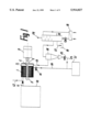
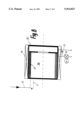
- FIG. 1 shows a reactor system according to the invention
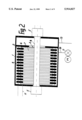
- FIG. 2 shows a longitudinal cross section of the reactor in FIG. 1,
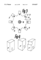
- FIG. 3 shows a rotor used in the reactor in FIG. 1 and 2
- FIG. 4 shows possible embodiments of friction elements
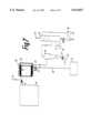
- FIG. 5 shows an alternative reactor system according to the invention
- FIG. 6 shows a longitudinal cross section of the reactor in FIG. 5
- FIG. 7 shows a further alternative reactor system according to the invention
- FIG. 8 shows a longitudinal cross section of the reactor in FIG. 7,
- FIG. 9 shows a third alternative reactor system according to the invention.
- FIG. 10 shows the reactor in FIG. 9 in greater scale.
- FIG. 2 shows a reactor chamber or vessel 1 with a rotor 2 including friction elements 3.
- the rotor 2 further includes a shaft 4 sealed in the reactor with mechanical seals 5.
- the friction elements 3 are pivotably mounted at G (see also FIG. 3) in the rotor plates 7.
- each pair of adjacent rotor plates 7 carries a number of friction elements 3 (the remaining elements in FIG. 3 belong to the next rotor plate pair).
- the friction elements 3 are staggered relative the next set of friction elements.
- lay-out there may of course be a total of eight friction elements in each set.
- the staggered arrangement is however believed to achieve a better turbulent action in the bed 8 (FIG. 2) of grained solids.
- the friction elements may have a number of forms, three of which being disclosed in FIG. 4a, b, and c.
- the forward or impact faces of the friction elements in FIG. 4 are depicted with the letter "F".
- the friction elements 3 are pivotable mounted in between adjacent rotor plates 7 by means of rods 6 extending over the length of the rotor 2.
- the rotor 2 is driven by a rotating source 9 which can be an electrical motor, a diesel engine, a gas or steam turbine or the like.
- the material is brought to the reactor from a hopper 10 by a feeding device 11 which may be a screw-conveyor, mono-pump or a similar transport device. If the material does not contain water, water can be added to the flow from the pipe 12.
- the cracked hydrocarbon gases and over-saturated steam is leaving the reactor via the pipe 12 and a cyclone 14 and proceed to a condenser unit 15 which can be a baffle tray condenser, a tubular condenser or a distillation tower.
- the different fractions of the oil can be separated directly from the recovered hydrocarbon gases.
- the heat from condensation is removed by an oil cooler 16 cooled either by water or air.
- the recovered oil is discharged from the condenser by a pipe 17 to a tank 18.
- the solids is leaving the reactor via a rotating valve 19 and a tansport device 20 which can be a screw or belt conveyor or an air transportation pipe system to a container 21.
- the solids separated from the cyclone 14 is transported via a rotating valve 22 to the container 21 either by being connected to the transport device 20 or directly to the container 21 by a cyclone transport device 23.
- Outlet for non-condensable gases is from the pipe 24 to a filter unit or to a flare tower or being accumulated in a pressure tank--not shown.
- FIG. 5 shows another lay-out of the reaction chamber 25 consisting of two concentric pipes of non-magnetic material with closed ends.
- the annulus 26 is filled with small steel balls which are brought into rotation by the rotor 27 having permanent or electrical charged magnets 28.
- the rotor rotates by means of the motor 29 the magnetic field will rotate the steel balls thus whipping the material fed into the reactor from the hopper 10.
- the outlet for the hydrocarbon gases, over-saturated steam and solid is as illustrated in the schematics of FIG. 1.
- FIG. 6 shows details of the reactor 25.
- the reactor 25 comprises two concentric tubular bodies 30 and 31 with annular plates 32 and 33 thus forming the annulus 26.
- the annulus 26 contains steel balls 34 which are brought to move by the rotor 27 having permanent or electrical charged magnets 28.
- FIG. 7 shows another lay-out of a reactor 35 made of non-magnetic material having an electrical coil 36 as in a synchronous motor surrounding the reactor.
- the reaction chamber contains steel balls 37 which is put into rotation when activating the coil 36 by alternating current similar to a synchronous electrical motor thus whipping the material fed into the reactor from the hopper 10.
- the outlet of the hydrocarbon gases, over-saturated steam and solids is as illustrated in the schematics of FIG. 1.
- FIG. 8 visualises details of the reactor 35.
- the reactor 35 comprises a vessel made of non-magnetic material having an electrical coil 36 surrounding the vessel.
- the vessel includes a reaction chamber 38 which contains steel balls 37. These steel balls are activated to move adjacent the chamber wall when the coil 36 is activated by alternating current.
- FIG. 9 and 10 show another lay-out of a reactor 40 made of a non-magnetic material surrounded with magnetic coils 41 as in a torrid magnet.
- the coils are activated with alternating current from a source 42.
- the hollow reactor is partly filled with either steel balls 43 or balls of magneto-strictive material that will oscillate when subject to an alternating magnetic field, thus applying mechanical forces to the material fed into the reactor from the hopper 10.
- steel balls When using steel balls only, the balls will rotate in the torrid reactor, thus whipping the material and creating mechanical generated heat in it.
- the outlet for the hydrocarbon gases, over-saturated steam and solids is as illustrated in the schematics of FIG. 1.
Abstract
Description
Claims (4)
Applications Claiming Priority (3)
| Application Number | Priority Date | Filing Date | Title |
|---|---|---|---|
| NO19943367A NO179753B1 (en) | 1994-09-12 | 1994-09-12 | Method and apparatus for thermomechanical cracking and hydration |
| NO943367 | 1994-09-12 | ||
| PCT/NO1995/000157 WO1996008544A1 (en) | 1994-09-12 | 1995-09-08 | Thermo-mechanical cracking and hydrogenation |
Related Parent Applications (1)
| Application Number | Title | Priority Date | Filing Date |
|---|---|---|---|
| PCT/NO1995/000157 Continuation WO1996008544A1 (en) | 1994-09-12 | 1995-09-08 | Thermo-mechanical cracking and hydrogenation |
Publications (1)
| Publication Number | Publication Date |
|---|---|
| US5914027A true US5914027A (en) | 1999-06-22 |
Family
ID=26648525
Family Applications (1)
| Application Number | Title | Priority Date | Filing Date |
|---|---|---|---|
| US08/814,333 Expired - Lifetime US5914027A (en) | 1994-09-12 | 1997-03-11 | Thermo-mechanical cracking and hydrogenation |
Country Status (1)
| Country | Link |
|---|---|
| US (1) | US5914027A (en) |
Cited By (28)
| Publication number | Priority date | Publication date | Assignee | Title |
|---|---|---|---|---|
| US6250386B1 (en) | 1997-01-16 | 2001-06-26 | Eureka Oil Asa | Process for stimulation of oil wells |
| US6485631B1 (en) | 1999-02-11 | 2002-11-26 | Ellycrack As | Process for thermal, and optionally catalytic, upgrading and hydrogenation of hydrocarbons |
| US6499536B1 (en) | 1997-12-22 | 2002-12-31 | Eureka Oil Asa | Method to increase the oil production from an oil reservoir |
| US6589417B2 (en) * | 1996-09-27 | 2003-07-08 | Alberta Oil Sands Tech And Research Authority | Thermal apparatus and process for removing contaminants from oil |
| US20040062647A1 (en) * | 2002-09-26 | 2004-04-01 | Garrett Norman H. | Roto-dynamic fluidic systems |
| WO2005070532A1 (en) * | 2002-12-24 | 2005-08-04 | Alan Mcgowan | Treatment of materials |
| US20050287025A1 (en) * | 2004-06-24 | 2005-12-29 | Fuel Fx International, Inc. | Method and apparatus for use in enhancing fuels |
| US20050284453A1 (en) * | 2004-06-24 | 2005-12-29 | Fuel Fx International, Inc. | Method and apparatus for use in enhancing fuels |
| US20060029491A1 (en) * | 2002-09-26 | 2006-02-09 | Garrett Norman H Iii | Roto-dynamic fluidic systems |
| US20080236160A1 (en) * | 2007-03-29 | 2008-10-02 | Victor Nikolaevich Glotov | Continuous flow sonic reactor |
| US20090098266A1 (en) * | 2007-10-10 | 2009-04-16 | Fernando Roberto Paz Briz | Method and apparatus for separating, purifying, promoting interaction and improving combustion |
| WO2009059124A2 (en) * | 2007-11-02 | 2009-05-07 | University Of Utah Research Foundation | Cyclic gaseous compression/expansion for heightened oil sands extraction |
| US20090114567A1 (en) * | 2007-11-07 | 2009-05-07 | Maxwell James F | Cracking hydrocarbonaceous materials with heating bodies |
| US20090120844A1 (en) * | 2006-05-15 | 2009-05-14 | Tarblaster As | Process for simultaneous recovery and cracking/upgrading of oil from solids |
| FR2925519A1 (en) * | 2007-12-20 | 2009-06-26 | Total France Sa | Fuel oil degrading method for petroleum field, involves mixing fuel oil and vector, and applying magnetic field such that mixture is heated and separated into two sections, where one section is lighter than another |
| FR2929287A1 (en) * | 2008-03-28 | 2009-10-02 | Europ Ltd | Liquid hydrocarbon obtaining method for engine, involves utilizing water and mixture of easy boiling fraction and recycled post-fractionation residue as hydrogen donor in hydrogen donor liquid medium |
| US20100176033A1 (en) * | 2009-01-15 | 2010-07-15 | Rapp Gary L | System for removing tar oil from sand and method of extracting oil from sand |
| US20110067305A1 (en) * | 2009-09-22 | 2011-03-24 | Martin Allan Morris | Hydrocarbon synthesizer |
| WO2011121623A1 (en) * | 2010-04-01 | 2011-10-06 | Giorgio Pecci | Apparatus for transforming long molecular chain organic matter |
| WO2013169414A1 (en) * | 2012-05-11 | 2013-11-14 | Caisson Technology Group LLC | Bubble implosion reactor cavitation device, subassembly, and methods for utilizing the same |
| US20150053545A1 (en) * | 2008-10-27 | 2015-02-26 | Cavitation Technologies,Inc. | Flow-through cavitation-assisted rapid modification of crude oil |
| US9080113B2 (en) | 2013-02-01 | 2015-07-14 | Lummus Technology Inc. | Upgrading raw shale-derived crude oils to hydrocarbon distillate fuels |
| WO2014187910A3 (en) * | 2013-05-22 | 2015-07-23 | Bfcc Tech Ltd | Hydrothermal decomposition method and apparatus for making pyrolysis liquid in the range of diesel fuel |
| US9546351B2 (en) | 2010-04-12 | 2017-01-17 | Industrias Centli, S.A. De C.V. | Method and system for processing biomass |
| US11059018B2 (en) | 2018-05-16 | 2021-07-13 | Dresser-Rand Company | Turbomachine chemical reactor and method for cracking hydrocarbons in a process fluid |
| US20210227870A1 (en) * | 2018-05-18 | 2021-07-29 | Penagos Hermanos Y Cia S.A.S. | Eco-friendly horizontal-axis hydrowasher for fermented coffee |
| US11123702B2 (en) | 2018-09-20 | 2021-09-21 | Dresser-Rand Company | Turbomachine type chemical reactor |
| RU2762549C1 (en) * | 2021-05-31 | 2021-12-21 | Акционерное общество «ПлазмаТЭК технолоджи» | Method for processing liquid hydrocarbonic paraffinic raw materials |
Citations (7)
| Publication number | Priority date | Publication date | Assignee | Title |
|---|---|---|---|---|
| US3282826A (en) * | 1963-04-30 | 1966-11-01 | Winkler Joseph | Depolymerization of bituminous coal utilizing friable metal reactants |
| US3963598A (en) * | 1974-10-15 | 1976-06-15 | The United States Of America As Represented By The United States Energy Research And Development Administration | Flash hydrogenation of coal |
| US4250015A (en) * | 1978-12-18 | 1981-02-10 | The United States Of America As Represented By The United States Department Of Energy | Mechanochemical hydrogenation of coal |
| US4287157A (en) * | 1979-10-27 | 1981-09-01 | Hermann Berstorff Maschinenbau Gmbh | Coal hydrogenating apparatus having means for sealing the rotary drive thereof |
| US4316873A (en) * | 1979-10-27 | 1982-02-23 | Hermann Berstorff Maschinenbau Gmbh | Apparatus for converting coal to hydrocarbons by hydrogenation |
| US4344835A (en) * | 1979-12-03 | 1982-08-17 | Hermann Berstorff Maschinenbau Gmbh | Method for monitoring and controlling hydrogenation pressure in plant for the hydrogenation of coal with hydrogen to form hydrocarbons |
| WO1994008680A1 (en) * | 1992-10-09 | 1994-04-28 | Olav Ellingsen | Method for selective and/or unselective vaporization and/or decomposition of, particularly, hydrocarbon compounds and apparatus for carrying out such a method |
-
1997
- 1997-03-11 US US08/814,333 patent/US5914027A/en not_active Expired - Lifetime
Patent Citations (8)
| Publication number | Priority date | Publication date | Assignee | Title |
|---|---|---|---|---|
| US3282826A (en) * | 1963-04-30 | 1966-11-01 | Winkler Joseph | Depolymerization of bituminous coal utilizing friable metal reactants |
| US3963598A (en) * | 1974-10-15 | 1976-06-15 | The United States Of America As Represented By The United States Energy Research And Development Administration | Flash hydrogenation of coal |
| US4250015A (en) * | 1978-12-18 | 1981-02-10 | The United States Of America As Represented By The United States Department Of Energy | Mechanochemical hydrogenation of coal |
| US4287157A (en) * | 1979-10-27 | 1981-09-01 | Hermann Berstorff Maschinenbau Gmbh | Coal hydrogenating apparatus having means for sealing the rotary drive thereof |
| US4316873A (en) * | 1979-10-27 | 1982-02-23 | Hermann Berstorff Maschinenbau Gmbh | Apparatus for converting coal to hydrocarbons by hydrogenation |
| US4344836A (en) * | 1979-10-27 | 1982-08-17 | Hermann Berstorff Maschinenbau Gmbh | Method for converting coal to hydrocarbons by hydrogenation |
| US4344835A (en) * | 1979-12-03 | 1982-08-17 | Hermann Berstorff Maschinenbau Gmbh | Method for monitoring and controlling hydrogenation pressure in plant for the hydrogenation of coal with hydrogen to form hydrocarbons |
| WO1994008680A1 (en) * | 1992-10-09 | 1994-04-28 | Olav Ellingsen | Method for selective and/or unselective vaporization and/or decomposition of, particularly, hydrocarbon compounds and apparatus for carrying out such a method |
Non-Patent Citations (2)
| Title |
|---|
| Abstract of (DE 3300365), Title:Carbonisation of of Residue From Hydrogenation of Heavy Oil or Coal In Rotating Drum, Heated in Rotating Drum, Heated Internally by Heated Carbonisation Prod. Gas, Jul. 12, 1984. * |
| Abstract of (DE 3300365), Title:Carbonisation of of Residue From Hydrogenation of Heavy Oil or Coal-In Rotating Drum, Heated in Rotating Drum, Heated Internally by Heated Carbonisation Prod. Gas, Jul. 12, 1984. |
Cited By (43)
| Publication number | Priority date | Publication date | Assignee | Title |
|---|---|---|---|---|
| US6589417B2 (en) * | 1996-09-27 | 2003-07-08 | Alberta Oil Sands Tech And Research Authority | Thermal apparatus and process for removing contaminants from oil |
| US6250386B1 (en) | 1997-01-16 | 2001-06-26 | Eureka Oil Asa | Process for stimulation of oil wells |
| US6499536B1 (en) | 1997-12-22 | 2002-12-31 | Eureka Oil Asa | Method to increase the oil production from an oil reservoir |
| US6485631B1 (en) | 1999-02-11 | 2002-11-26 | Ellycrack As | Process for thermal, and optionally catalytic, upgrading and hydrogenation of hydrocarbons |
| US6974305B2 (en) | 2002-09-26 | 2005-12-13 | Garrett Iii Norman H | Roto-dynamic fluidic systems |
| US20060029491A1 (en) * | 2002-09-26 | 2006-02-09 | Garrett Norman H Iii | Roto-dynamic fluidic systems |
| US20040062647A1 (en) * | 2002-09-26 | 2004-04-01 | Garrett Norman H. | Roto-dynamic fluidic systems |
| WO2005070532A1 (en) * | 2002-12-24 | 2005-08-04 | Alan Mcgowan | Treatment of materials |
| US20050287025A1 (en) * | 2004-06-24 | 2005-12-29 | Fuel Fx International, Inc. | Method and apparatus for use in enhancing fuels |
| US20050284453A1 (en) * | 2004-06-24 | 2005-12-29 | Fuel Fx International, Inc. | Method and apparatus for use in enhancing fuels |
| US7383828B2 (en) | 2004-06-24 | 2008-06-10 | Emission & Power Solutions, Inc. | Method and apparatus for use in enhancing fuels |
| US7428896B2 (en) | 2004-06-24 | 2008-09-30 | Emission & Power Solutions, Inc. | Method and apparatus for use in enhancing fuels |
| US20090120844A1 (en) * | 2006-05-15 | 2009-05-14 | Tarblaster As | Process for simultaneous recovery and cracking/upgrading of oil from solids |
| US20080236160A1 (en) * | 2007-03-29 | 2008-10-02 | Victor Nikolaevich Glotov | Continuous flow sonic reactor |
| US7767159B2 (en) * | 2007-03-29 | 2010-08-03 | Victor Nikolaevich Glotov | Continuous flow sonic reactor and method |
| WO2009048313A2 (en) * | 2007-10-10 | 2009-04-16 | Industrias Centli, S.A., De C.V. | Method and apparatus for separating, purifying and promoting interaction and enhancing combustion |
| US20090098266A1 (en) * | 2007-10-10 | 2009-04-16 | Fernando Roberto Paz Briz | Method and apparatus for separating, purifying, promoting interaction and improving combustion |
| US7887862B2 (en) | 2007-10-10 | 2011-02-15 | Industrias Centli S.A. De C.V. | Method and apparatus for separating, purifying, promoting interaction and improving combustion |
| WO2009048313A3 (en) * | 2007-10-10 | 2010-01-07 | Industrias Centli, S.A., De C.V. | Method and apparatus for separating, purifying and promoting interaction and enhancing combustion |
| US20110095111A1 (en) * | 2007-10-10 | 2011-04-28 | Industrias Centli S.A. De C.V. | Method and apparatus for separating, purifying, promoting interaction and improving combustion |
| WO2009059124A2 (en) * | 2007-11-02 | 2009-05-07 | University Of Utah Research Foundation | Cyclic gaseous compression/expansion for heightened oil sands extraction |
| WO2009059124A3 (en) * | 2007-11-02 | 2009-08-13 | Univ Utah Res Found | Cyclic gaseous compression/expansion for heightened oil sands extraction |
| US20100307959A1 (en) * | 2007-11-02 | 2010-12-09 | Andy Hong | Cyclic gaseous compression/extraction for heightened oil sands extraction |
| US20090114567A1 (en) * | 2007-11-07 | 2009-05-07 | Maxwell James F | Cracking hydrocarbonaceous materials with heating bodies |
| FR2925519A1 (en) * | 2007-12-20 | 2009-06-26 | Total France Sa | Fuel oil degrading method for petroleum field, involves mixing fuel oil and vector, and applying magnetic field such that mixture is heated and separated into two sections, where one section is lighter than another |
| FR2929287A1 (en) * | 2008-03-28 | 2009-10-02 | Europ Ltd | Liquid hydrocarbon obtaining method for engine, involves utilizing water and mixture of easy boiling fraction and recycled post-fractionation residue as hydrogen donor in hydrogen donor liquid medium |
| US9719025B2 (en) * | 2008-10-27 | 2017-08-01 | Cavitation Technologies, Inc. | Flow-through cavitation-assisted rapid modification of crude oil |
| US20150053545A1 (en) * | 2008-10-27 | 2015-02-26 | Cavitation Technologies,Inc. | Flow-through cavitation-assisted rapid modification of crude oil |
| US20100176033A1 (en) * | 2009-01-15 | 2010-07-15 | Rapp Gary L | System for removing tar oil from sand and method of extracting oil from sand |
| US20110067305A1 (en) * | 2009-09-22 | 2011-03-24 | Martin Allan Morris | Hydrocarbon synthesizer |
| US8858783B2 (en) | 2009-09-22 | 2014-10-14 | Neo-Petro, Llc | Hydrocarbon synthesizer |
| WO2011121623A1 (en) * | 2010-04-01 | 2011-10-06 | Giorgio Pecci | Apparatus for transforming long molecular chain organic matter |
| US9546351B2 (en) | 2010-04-12 | 2017-01-17 | Industrias Centli, S.A. De C.V. | Method and system for processing biomass |
| US9126176B2 (en) | 2012-05-11 | 2015-09-08 | Caisson Technology Group LLC | Bubble implosion reactor cavitation device, subassembly, and methods for utilizing the same |
| US9682356B2 (en) | 2012-05-11 | 2017-06-20 | Kcs678 Llc | Bubble implosion reactor cavitation device, subassembly, and methods for utilizing the same |
| WO2013169414A1 (en) * | 2012-05-11 | 2013-11-14 | Caisson Technology Group LLC | Bubble implosion reactor cavitation device, subassembly, and methods for utilizing the same |
| US9080113B2 (en) | 2013-02-01 | 2015-07-14 | Lummus Technology Inc. | Upgrading raw shale-derived crude oils to hydrocarbon distillate fuels |
| US9725661B2 (en) | 2013-02-01 | 2017-08-08 | Lummus Technology Inc. | Upgrading raw shale-derived crude oils to hydrocarbon distillate fuels |
| WO2014187910A3 (en) * | 2013-05-22 | 2015-07-23 | Bfcc Tech Ltd | Hydrothermal decomposition method and apparatus for making pyrolysis liquid in the range of diesel fuel |
| US11059018B2 (en) | 2018-05-16 | 2021-07-13 | Dresser-Rand Company | Turbomachine chemical reactor and method for cracking hydrocarbons in a process fluid |
| US20210227870A1 (en) * | 2018-05-18 | 2021-07-29 | Penagos Hermanos Y Cia S.A.S. | Eco-friendly horizontal-axis hydrowasher for fermented coffee |
| US11123702B2 (en) | 2018-09-20 | 2021-09-21 | Dresser-Rand Company | Turbomachine type chemical reactor |
| RU2762549C1 (en) * | 2021-05-31 | 2021-12-21 | Акционерное общество «ПлазмаТЭК технолоджи» | Method for processing liquid hydrocarbonic paraffinic raw materials |
Similar Documents
| Publication | Publication Date | Title |
|---|---|---|
| US5914027A (en) | Thermo-mechanical cracking and hydrogenation | |
| US20100051511A1 (en) | Method For Releasing Organics From Shale And Like Materials To Produce A Liquid Shale Fuel | |
| US9719025B2 (en) | Flow-through cavitation-assisted rapid modification of crude oil | |
| RU2181126C2 (en) | Method and device for thermal and/or catalytic decomposition and/or depolymerization of lower organic matters | |
| EP0781313B1 (en) | Thermo-mechanical cracking and hydrogenation | |
| CA2778964C (en) | Bitumen extraction and asphaltene removal from heavy crude using high shear | |
| US20050077241A1 (en) | Method and apparatus for continuous separation and reaction using supercritical fluid | |
| WO2002102937A1 (en) | Method to treat emulsified hydrocarbon mixtures | |
| BRPI1001712A2 (en) | hydroconversion process and hydroconversion product composition | |
| WO2002103322A2 (en) | Method to liberate hydrocarbon fractions from hydrocarbon mixtures | |
| RU88670U1 (en) | INSTALLATION AND DEVICES OF DEPTHE PROCESSING OF HYDROCARBON RAW MATERIALS | |
| Sawarkar et al. | Use of ultrasound in petroleum residue upgradation | |
| RU114955U1 (en) | INSTALLATION AND DEVICES OF DEPTHE PROCESSING OF HYDROCARBON RAW MATERIALS | |
| KR20150110636A (en) | System and process for thermal cracking and steam cracking | |
| RU2203924C1 (en) | Liquid hydrocarbon production process | |
| RU2782934C1 (en) | Plant for the treatment of liquid hydrocarbon waxy raw materials | |
| RU2762549C1 (en) | Method for processing liquid hydrocarbonic paraffinic raw materials | |
| RU78793U1 (en) | SCHEME FOR PREPARATION AND IN-DEPTH PROCESSING OF HYDROCARBON RAW MATERIALS | |
| RU2778516C1 (en) | Method for primary processing of hydrocarbon raw materials using ultrasonic vibrations and chemical reagents | |
| Hmood | Upgrading of basrah-kirkuk blend crude oil using mechanical-acoustical effect | |
| Yen | [17] P3 Upgrading Through Cavitation and Surfactant | |
| RU2618221C1 (en) | Oil cracking installation and method of oil cracking by means of this installation | |
| Zakieva et al. | Super-viscous oil conversion in supercritical water fluid | |
| VG Sister, ¹ ES Gridneva, ¹ and OV Abramov²* | Ultrasound-induced change in chemical properties of petroleum products | |
| Rahman | Demulsification of water in oil emulsion using microwave technique |
Legal Events
| Date | Code | Title | Description |
|---|---|---|---|
| AS | Assignment |
Owner name: THERMTECH A/S, NORWAY Free format text: ASSIGNMENT OF ASSIGNORS INTEREST;ASSIGNOR:ELLINGSEN, OLAV;REEL/FRAME:008455/0400 Effective date: 19970221 |
|
| STCF | Information on status: patent grant |
Free format text: PATENTED CASE |
|
| FEPP | Fee payment procedure |
Free format text: PAYOR NUMBER ASSIGNED (ORIGINAL EVENT CODE: ASPN); ENTITY STATUS OF PATENT OWNER: SMALL ENTITY Free format text: PAYER NUMBER DE-ASSIGNED (ORIGINAL EVENT CODE: RMPN); ENTITY STATUS OF PATENT OWNER: SMALL ENTITY |
|
| FPAY | Fee payment |
Year of fee payment: 4 |
|
| REMI | Maintenance fee reminder mailed | ||
| FPAY | Fee payment |
Year of fee payment: 8 |
|
| FEPP | Fee payment procedure |
Free format text: PAYER NUMBER DE-ASSIGNED (ORIGINAL EVENT CODE: RMPN); ENTITY STATUS OF PATENT OWNER: SMALL ENTITY Free format text: PAYOR NUMBER ASSIGNED (ORIGINAL EVENT CODE: ASPN); ENTITY STATUS OF PATENT OWNER: SMALL ENTITY |
|
| FEPP | Fee payment procedure |
Free format text: PAYOR NUMBER ASSIGNED (ORIGINAL EVENT CODE: ASPN); ENTITY STATUS OF PATENT OWNER: SMALL ENTITY Free format text: PAYER NUMBER DE-ASSIGNED (ORIGINAL EVENT CODE: RMPN); ENTITY STATUS OF PATENT OWNER: SMALL ENTITY |
|
| FPAY | Fee payment |
Year of fee payment: 12 |