US6150753A - Ultrasonic transducer assembly having a cobalt-base alloy housing - Google Patents
Ultrasonic transducer assembly having a cobalt-base alloy housing Download PDFInfo
- Publication number
- US6150753A US6150753A US08/990,437 US99043797A US6150753A US 6150753 A US6150753 A US 6150753A US 99043797 A US99043797 A US 99043797A US 6150753 A US6150753 A US 6150753A
- Authority
- US
- United States
- Prior art keywords
- transducer
- ultrasonic
- ultrasonic transducer
- brazing
- housing
- Prior art date
- Legal status (The legal status is an assumption and is not a legal conclusion. Google has not performed a legal analysis and makes no representation as to the accuracy of the status listed.)
- Expired - Lifetime
Links
Images
Classifications
-
- B—PERFORMING OPERATIONS; TRANSPORTING
- B08—CLEANING
- B08B—CLEANING IN GENERAL; PREVENTION OF FOULING IN GENERAL
- B08B3/00—Cleaning by methods involving the use or presence of liquid or steam
- B08B3/04—Cleaning involving contact with liquid
- B08B3/10—Cleaning involving contact with liquid with additional treatment of the liquid or of the object being cleaned, e.g. by heat, by electricity or by vibration
- B08B3/12—Cleaning involving contact with liquid with additional treatment of the liquid or of the object being cleaned, e.g. by heat, by electricity or by vibration by sonic or ultrasonic vibrations
-
- G—PHYSICS
- G10—MUSICAL INSTRUMENTS; ACOUSTICS
- G10K—SOUND-PRODUCING DEVICES; METHODS OR DEVICES FOR PROTECTING AGAINST, OR FOR DAMPING, NOISE OR OTHER ACOUSTIC WAVES IN GENERAL; ACOUSTICS NOT OTHERWISE PROVIDED FOR
- G10K11/00—Methods or devices for transmitting, conducting or directing sound in general; Methods or devices for protecting against, or for damping, noise or other acoustic waves in general
- G10K11/02—Mechanical acoustic impedances; Impedance matching, e.g. by horns; Acoustic resonators
Definitions
- This invention relates generally to ultrasonic cleaning, more particularly to ultrasonic transducer assemblies, and, more specifically, to an ultrasonic transducer assembly having a cobalt-base alloy housing.
- Aqueous and semi-aqueous cleaners are the only viable options left for many applications. Ultrasonic excitation boosts the effectiveness of aqueous and semi-aqueous cleaners to exceed the quality and cost standards previously obtained by the use of solvents. Ultrasonic methods provide the ultimate in cleaning effectiveness and speed to satisfy the needs of the changing environmentally-sensitive manufacturing world.
- Ultrasonic energy has the ability to reach inside partially closed areas such as part interiors, blind holes and crevices to give a mechanical boost to chemical cleaning where the use of a brush or other means is either impossible, ineffective, or time consuming.
- this may include cleaning the interior or a transmission housing weighing several hundred pounds or on a micro scale, removing buffing compound residue from filigree work on expensive jewelry.
- the thoroughness of ultrasonic cleaning cannot be matched by any other method.
- a solid state electronic generator converts standard electrical current into electrical energy of a higher frequency (typically 10-200 KHz).
- a transducer then converts this energy into mechanical waves.
- These transducers are either bonded to the exterior wall of a tank, or are enclosed in a stainless steel immersible housing which is mounted inside a tank.
- the sound waves produced by these transducers cause disruption of the liquid as alternative positive and negative pressure areas are produced resulting in vacuum cavities or cavitation bubbles.
- These bubbles are created during negative pressure periods, grow larger over several cycles and then collapse.
- the pressure exerted by the imploding bubbles accomplishes a scrubbing action which results in rapid, efficient and gentle cleaning.
- the small size of the bubbles permits their penetration into areas that cannot be reached using brushes or sprays.
- the cleaning fluid is corrosive. This requires that the ultrasonic cleaning tank be made of a compatible corrosion-resistant material, such as stainless steel, quartz or a more exotic material for certain acids. It also is imperative that the transducer be properly coupled to the liquid so that the ultrasonic energy is effectively transferred from the transducer to the liquid in the tank.
- a preferred method of attachment of the transducer element to the exterior wall of the tank or to the immersible housing is vacuum brazing. Since vacuum brazing is best accomplished between two similar metals, transducers have, in the past, been secured to a stainless steel brazing mass (by epoxy, for example) and the brazing mass was brazed to the wall of the tank. A preferred method is that of vacuum brazing.
- the materials of which the ultrasonic tank are made are attacked at the point of maximum vibration by these same mechanisms over long hours of operation.
- surface coatings such as hard chrome and titanium nitride have been used in the industry for many years. These materials reduce cavitation erosion which is considered to be a mechanical mechanism, by increasing the surface hardness.
- a 2 mil hard chrome coating has a Rockwell C hardness of 60, as compared to 25 for 316L stainless steel. Endurance testing has shown a reduction in surface cavitation erosion by a factor of 10.
- a new cobalt-base alloy has demonstrated resistance to cavitation erosion and corrosion.
- This alloy sold under the trademark ULTIMET® by Haynes International, Inc. of Kokomo, Ind., demonstrates high elastic resilience, high yield strength and phase transformations. The alloy also demonstrates high resistance to cyclic fatigue.
- no one has as yet used this alloy in a housing of an ultrasonic cleaning apparatus Perhaps one reason for this is the high cost of the alloy. Perhaps another reason is that no one has heretofore discovered how to vacuum braze a stainless steel brazing element to the cobalt-base alloy wall (since it is cost prohibitive to construct the brazing disk from cobalt-base alloy as well).
- an ultrasonic cleaning apparatus having a tank constructed of one material and brazing member constructed of another dissimilar material creates problems that must be solved Copper or other metallic vacuum brazing requires that the parts to be brazed be slowly heated in a vacuum chamber to 2000° F. at which point the copper melts and surface tension holds the parts closely together. With dissimilar materials being brazed, one of the materials will have expanded more or less than the other. As the parts are cooled, the copper solidifies joining the parts together but as additional cooling occurs the parts are under considerable stress due to the difference in thermal expansion of the parts. This results in a distortion of the parts and typically a concave shape on the stainless steel brazing mass and a convex shape to the outer cobalt-base alloy material. In summary, welding of the two dissimilar metals does not provide optimum coupling. Vacuum brazing is preferred but difficult to achieve.
- an ultrasonic transducer assembly having a cobalt-base alloy housing, and a means to compensate for the distortion of the parts during the production process.
- the present invention broadly comprises an ultrasonic transducer assembly, having a cobalt-base alloy housing with at least one planar wall section, and at least one ultrasonic transducer mounted to the planar wall section, the ultrasonic transducer operatively arranged to impart an ultrasonic vibrating force to the planar wall section of the housing.
- the ultrasonic transducer comprises piezoelectric crystals sandwiched between two alloy members.
- a primary object of the present invention is to provide an ultrasonic transducer assembly that is durable in a corrosive environment, having a cobalt-base alloy housing.
- a secondary object of the present invention is to provide an ultrasonic transducer assembly comprising one or more ultrasonic transducers secured by vacuum brazing to a cobalt-base alloy housing.
- FIG. 1 is a perspective view of the transducer assembly of the present invention
- FIG. 2 is a front exploded view of a prior art ultrasonic transducer assembly
- FIG. 3 is a front exploded view of the ultrasonic transducer assembly shown in FIG. 1;
- FIG. 4 is a front fragmentary cross-sectional view of the ultrasonic transducer assembly shown in FIG. 1;
- FIG. 5 illustrates a plurality of the ultrasonic transducers of the present invention mounted within an immersible housing
- FIG. 6 illustrates a plurality of the housings shown in FIG. 5 mounted within an ultrasonic cleaning tank
- FIG. 7 illustrates an alternative embodiment of the present invention
- FIG. 8 is a front exploded view of the embodiment of the invention shown in FIG. 7;
- FIG. 9 illustrates a plurality of the transducers shown in FIG. 7 secured to the exterior bottom wall of an ultrasonic cleaning tank
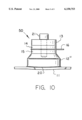
- FIG. 10 illustrates yet another embodiment of the invention where the second transducer member is secured to the wall of the housing directly, either by vacuum brazing or epoxy.
- the ultrasonic transducer assembly is seen to include at least one ultrasonic transducer 10 mounted to a cobalt-base alloy wall 11 of a housing.
- Transducer 10 comprises first transducer member 13, second transducer member 12, a pair of piezoelectric crystals 14 and 15 positioned atop one another and sandwiched between the first and second transducer members, a first electrode 16 electrically connected to said crystals, and a second electrode 17 electrically connected to said crystals.
- the crystals are connected to a source of electrical energy which causes them to vibrate at a predetermined frequency as is well known in the art. Typically, the crystals are caused to vibrate at frequencies in the range of 20-170 KHz. When an appropriate voltage is applied across the electrodes, the crystals impart an ultrasonic vibrating force to the first and second transducer members, which force is then imparted to wall 11.
- wall 11 is comprised of a cobalt-base alloy.
- ULTIMET® is a cobalt-chromium alloy having a nominal chemical composition (weight percent) as follows: cobalt (54%), chromium (26%), nickel (9%), molybdenum (5%), tungsten (2%), and iron (3%).
- the alloy also contains trace amounts (less than 1% weight percent) of manganese, silicon, nitrogen and carbon.
- the manufacturer of ULTIMET® advertises that the alloy is an ideal welding material, it is not advisable to weld the transducer to the wall of the housing in the present invention, because welding does not provide optimum coupling of the transducer to the wall.
- FIG. 2 illustrates in exploded view how a prior art transducer is vacuum brazed to a stainless steel wall 11' of a transducer assembly wall.
- second transducer member 12 is mounted to brazing element 18 by bolts 22 which engage threaded partial through-bores 22'.
- the element is further secured to brazing member 18 by a layer of epoxy 19.
- the brazing element is typically made of stainless steel, and is vacuum brazed to stainless steel wall 11' using brazed material 20.
- FIG. 3 illustrates, in exploded view, the present invention.
- brazing member 18 is brazed to cobalt alloy wall 11.
- the upper surface 24 becomes deformed as illustrated by dotted line in the drawing.
- surface 24 becomes concave as a result of deformation during brazing.
- the actual deformation is exaggerated in FIG. 3.
- second member 12 of transducer 10 does not perfectly mate with brazing member 18 to form an effective coupling.
- the inventor has found that is necessary to machine a convex exterior surface 23 into second member 12.
- FIG. 4 shows in fragmentary cross-sectional view the transducer as it has been brazed to the wall of the transducer assembly.
- An alternative technique to overcome this problem is to pre-machine a convex shape on the top surface of brazing element 18 so that a flat surface results following member 18 being brazed to plate 11.
- FIG. 5 illustrates a plurality of transducers 10 brazed to a wall of an enclosure of a housing 25. Also shown in the drawings is electrical cable 26 which is used to transmit electrical energy to the individual transducers via leads 27. Also shown schematically in the drawing are ultrasonic waves 28 produced by the plurality of the transducers which transmit ultrasonic energy to the wall of the enclosure.
- FIG. 6 illustrates another embodiment of the ultrasonic transducer assembly.
- a plurality of enclosures 25 are mounted to the interior walls of a larger enclosure 30.
- Articles to be ultrasonically cleaned would be placed in the housing 30 and immersed in solution.
- FIG. 7 illustrates in perspective view an alternative embodiment of the present invention.
- transducer 40 threadably engages a stud on cobalt alloy wall 11.
- the transducer is further secured to the wall by a layer of epoxy.
- This mounting assembly is best illustrated in FIG. 8 which shows in exploded view how transducer 40 threadably engages stud 31 which protrudes from wall 11 and is further secured by epoxy layer 19.
- FIG. 9 illustrates an application which uses transducer assembly 40 shown in FIG. 8.
- a plurality of transducers 40 are secured to the bottom wall of housing 32. Ultrasonic vibrations produced by the transducers are transmitted through the bottom wall and into the fluid medium 33.
- FIG. 10 illustrates yet another embodiment 50 of the invention.
- the second transducer member is secured to the wall of the housing directly, either by epoxy or vacuum brazing (vacuum brazing is illustrated in the drawing).
- the bottom surface of the second transducer member is machined to form a convex shape as discussed supra. After brazing the bottom surface of the second member and the wall create a high integrity acoustic coupling.
- first transducer element 13 may be comprised of cold-rolled steel, aluminum, brass, stainless steel or other materials.
- Second transducer element 12 may be comprised of titanium, stainless steel, aluminum, cold rolled steel, brass or other materials. It is not necessary that both the first and second elements are made of the same material. It is also possible to braze or otherwise secure the second transducer element directly to the wall.
- transducer member 12 may be made of titanium or another metal, and may be brazed directly to the wall.
- the second member can be made of a different material than the wall, it is likely that the above-described differences in coefficients of thermal expansion between the second member and the wall will create mating problems. These problems, which have been extensively discussed supra, can be solved by machining a convex shaped surface on the bottom of the second member as shown in FIG. 10. It should be noted further that the second member can be in any number of shapes. For example, the member can be a solid cylinder, a frustoconical shape, etc.
Abstract
Description
Claims (8)
Priority Applications (1)
| Application Number | Priority Date | Filing Date | Title |
|---|---|---|---|
| US08/990,437 US6150753A (en) | 1997-12-15 | 1997-12-15 | Ultrasonic transducer assembly having a cobalt-base alloy housing |
Applications Claiming Priority (1)
| Application Number | Priority Date | Filing Date | Title |
|---|---|---|---|
| US08/990,437 US6150753A (en) | 1997-12-15 | 1997-12-15 | Ultrasonic transducer assembly having a cobalt-base alloy housing |
Publications (1)
| Publication Number | Publication Date |
|---|---|
| US6150753A true US6150753A (en) | 2000-11-21 |
Family
ID=25536150
Family Applications (1)
| Application Number | Title | Priority Date | Filing Date |
|---|---|---|---|
| US08/990,437 Expired - Lifetime US6150753A (en) | 1997-12-15 | 1997-12-15 | Ultrasonic transducer assembly having a cobalt-base alloy housing |
Country Status (1)
| Country | Link |
|---|---|
| US (1) | US6150753A (en) |
Cited By (29)
| Publication number | Priority date | Publication date | Assignee | Title |
|---|---|---|---|---|
| US20020171331A1 (en) * | 1996-08-05 | 2002-11-21 | Puskas William L. | Apparatus and methods for cleaning and/or processing delicate parts |
| US20040094603A1 (en) * | 2002-11-14 | 2004-05-20 | Stegelmann Norman R. | Ultrasonic horn assembly with fused stack components |
| US20040251773A1 (en) * | 2003-02-04 | 2004-12-16 | Russell Manchester | Ultrasonic cleaning tank |
| US20050017599A1 (en) * | 1996-08-05 | 2005-01-27 | Puskas William L. | Apparatus, circuitry, signals and methods for cleaning and/or processing with sound |
| US20050122003A1 (en) * | 2003-11-05 | 2005-06-09 | Goodson J. M. | Ultrasonic processing method and apparatus with multiple frequency transducers |
| US20060086604A1 (en) * | 1996-09-24 | 2006-04-27 | Puskas William L | Organism inactivation method and system |
| US20060151203A1 (en) * | 2002-08-22 | 2006-07-13 | Hans Krueger | Encapsulated electronic component and production method |
| US20070182285A1 (en) * | 2004-11-05 | 2007-08-09 | Goodson J M | Megasonic processing apparatus with frequency sweeping of thickness mode transducers |
| US20070205695A1 (en) * | 1996-08-05 | 2007-09-06 | Puskas William L | Apparatus, circuitry, signals, probes and methods for cleaning and/or processing with sound |
| US20070222056A1 (en) * | 2004-04-22 | 2007-09-27 | Epcos Ag | Encapsulated Electrical Component and Production Method |
| US20080038577A1 (en) * | 2004-08-12 | 2008-02-14 | Epcos Ag | Component Arrangement Provided With a Carrier Substrate |
| US7336019B1 (en) | 2005-07-01 | 2008-02-26 | Puskas William L | Apparatus, circuitry, signals, probes and methods for cleaning and/or processing with sound |
| US20080047575A1 (en) * | 1996-09-24 | 2008-02-28 | Puskas William L | Apparatus, circuitry, signals and methods for cleaning and processing with sound |
| US20080142037A1 (en) * | 2006-12-19 | 2008-06-19 | Dempski James L | Apparatus and method for cleaning liquid dispensing equipment |
| US20090127697A1 (en) * | 2005-10-20 | 2009-05-21 | Wolfgang Pahl | Housing with a Cavity for a Mechanically-Sensitive Electronic Component and Method for Production |
| US20100275949A1 (en) * | 2008-09-22 | 2010-11-04 | Ruhge Forrest R | Ultrasonic coating removal method |
| US8169041B2 (en) | 2005-11-10 | 2012-05-01 | Epcos Ag | MEMS package and method for the production thereof |
| US8184845B2 (en) | 2005-02-24 | 2012-05-22 | Epcos Ag | Electrical module comprising a MEMS microphone |
| US8229139B2 (en) | 2005-11-10 | 2012-07-24 | Epcos Ag | MEMS microphone, production method and method for installing |
| US20130048698A1 (en) * | 2011-08-31 | 2013-02-28 | Lg Chem, Ltd. | Ultrasonic welding machine and method of assembling the ultrasonic welding machine |
| US8403019B2 (en) | 2010-05-24 | 2013-03-26 | Lg Chem, Ltd. | Ultrasonic welding assembly and method of attaching an anvil to a bracket of the assembly |
| US8517078B1 (en) | 2012-07-24 | 2013-08-27 | Lg Chem, Ltd. | Ultrasonic welding assembly and method of attaching an anvil to a bracket of the assembly |
| US8582788B2 (en) | 2005-02-24 | 2013-11-12 | Epcos Ag | MEMS microphone |
| US8640760B2 (en) | 2011-08-19 | 2014-02-04 | Lg Chem, Ltd. | Ultrasonic welding machine and method of aligning an ultrasonic welding horn relative to an anvil |
| US9005799B2 (en) | 2010-08-25 | 2015-04-14 | Lg Chem, Ltd. | Battery module and methods for bonding cell terminals of battery cells together |
| US9034129B2 (en) | 2011-01-13 | 2015-05-19 | Lg Chem, Ltd. | Ultrasonic welding system and method for forming a weld joint utilizing the ultrasonic welding system |
| US9556022B2 (en) * | 2013-06-18 | 2017-01-31 | Epcos Ag | Method for applying a structured coating to a component |
| US20180147611A1 (en) * | 2016-11-29 | 2018-05-31 | 1863815 Ontario Limited | Apparatus, System and Method for Cleaning Inner Surfaces of Tubing |
| US10052667B2 (en) * | 2013-03-15 | 2018-08-21 | Dominion Engineering, Inc. | Ultrasonically cleaning vessels and pipes |
Citations (5)
| Publication number | Priority date | Publication date | Assignee | Title |
|---|---|---|---|---|
| US3094314A (en) * | 1960-08-02 | 1963-06-18 | Detrex Chem Ind | Sandwich type transducer and coupling |
| US3113761A (en) * | 1961-07-26 | 1963-12-10 | Ultrasonic Ind Inc | Ultrasonic tank housing |
| US3318578A (en) * | 1965-03-22 | 1967-05-09 | Branson Instr | Cleaning apparatus |
| US3329408A (en) * | 1965-03-29 | 1967-07-04 | Branson Instr | Transducer mounting arrangement |
| US5119840A (en) * | 1986-04-07 | 1992-06-09 | Kaijo Kenki Co., Ltd. | Ultrasonic oscillating device and ultrasonic washing apparatus using the same |
-
1997
- 1997-12-15 US US08/990,437 patent/US6150753A/en not_active Expired - Lifetime
Patent Citations (5)
| Publication number | Priority date | Publication date | Assignee | Title |
|---|---|---|---|---|
| US3094314A (en) * | 1960-08-02 | 1963-06-18 | Detrex Chem Ind | Sandwich type transducer and coupling |
| US3113761A (en) * | 1961-07-26 | 1963-12-10 | Ultrasonic Ind Inc | Ultrasonic tank housing |
| US3318578A (en) * | 1965-03-22 | 1967-05-09 | Branson Instr | Cleaning apparatus |
| US3329408A (en) * | 1965-03-29 | 1967-07-04 | Branson Instr | Transducer mounting arrangement |
| US5119840A (en) * | 1986-04-07 | 1992-06-09 | Kaijo Kenki Co., Ltd. | Ultrasonic oscillating device and ultrasonic washing apparatus using the same |
Non-Patent Citations (8)
| Title |
|---|
| ASTM Standard Test Method for Cavitation Erosion using Vibratory Apparatus, Designation G 32 92, Jul. 1992. * |
| ASTM Standard Test Method for Cavitation Erosion using Vibratory Apparatus, Designation G 32-92, Jul. 1992. |
| Cavitation Erosion, A. Thiruvengadam, Applied Mechanics Reviews (Date unknown). * |
| Correlation of cavitation erosion behavior with mechanical properties of metals, R.H. Richman and W.P. McNaughton, Elsevier Sequoia, 1990. * |
| Practical Guide to Wear for Corrosion Engineers, Paul Crook, 1991, Materials Performance. * |
| The Effect of Composition and Microstructure on Cavitation Erosion Resistance, K.C. Antony and W.L. Silence, Proc. 5th Intl. Conf. on Erosion by Solid and Liquid Impact, (Date unknown). * |
| ULTIMET alloy, published by Haynes International producer of ULTIMET alloy, 1994. * |
| ULTIMET product, published by Haynes International, Mar. 8, 1995. * |
Cited By (52)
| Publication number | Priority date | Publication date | Assignee | Title |
|---|---|---|---|---|
| US6946773B2 (en) | 1996-08-05 | 2005-09-20 | Puskas William L | Apparatus and methods for cleaning and/or processing delicate parts |
| US20020171331A1 (en) * | 1996-08-05 | 2002-11-21 | Puskas William L. | Apparatus and methods for cleaning and/or processing delicate parts |
| US8075695B2 (en) | 1996-08-05 | 2011-12-13 | Puskas William L | Apparatus, circuitry, signals, probes and methods for cleaning and/or processing with sound |
| US20040182414A1 (en) * | 1996-08-05 | 2004-09-23 | Puskas William L. | Apparatus and methods for cleaning and/or processing delicate parts |
| US20070205695A1 (en) * | 1996-08-05 | 2007-09-06 | Puskas William L | Apparatus, circuitry, signals, probes and methods for cleaning and/or processing with sound |
| US20050017599A1 (en) * | 1996-08-05 | 2005-01-27 | Puskas William L. | Apparatus, circuitry, signals and methods for cleaning and/or processing with sound |
| US7211928B2 (en) | 1996-08-05 | 2007-05-01 | Puskas William L | Apparatus, circuitry, signals and methods for cleaning and/or processing with sound |
| US6914364B2 (en) * | 1996-08-05 | 2005-07-05 | William L. Puskas | Apparatus and methods for cleaning and/or processing delicate parts |
| US20080047575A1 (en) * | 1996-09-24 | 2008-02-28 | Puskas William L | Apparatus, circuitry, signals and methods for cleaning and processing with sound |
| US20060086604A1 (en) * | 1996-09-24 | 2006-04-27 | Puskas William L | Organism inactivation method and system |
| US20060151203A1 (en) * | 2002-08-22 | 2006-07-13 | Hans Krueger | Encapsulated electronic component and production method |
| US7388281B2 (en) | 2002-08-22 | 2008-06-17 | Epcos Ag | Encapsulated electronic component and production method |
| US20040094603A1 (en) * | 2002-11-14 | 2004-05-20 | Stegelmann Norman R. | Ultrasonic horn assembly with fused stack components |
| US6786383B2 (en) * | 2002-11-14 | 2004-09-07 | Kimberly-Clark Worldwide, Inc. | Ultrasonic horn assembly with fused stack components |
| US20040251773A1 (en) * | 2003-02-04 | 2004-12-16 | Russell Manchester | Ultrasonic cleaning tank |
| US20060113873A1 (en) * | 2003-02-04 | 2006-06-01 | Forward Technology A Crest Group Company | Ultrasonic cleaning tank |
| US7208858B2 (en) | 2003-02-04 | 2007-04-24 | Forward Technology A Crest Group Company | Ultrasonic cleaning tank |
| US7019440B2 (en) * | 2003-02-04 | 2006-03-28 | Forward Technology A Crest Group Company | Ultrasonic cleaning tank |
| US20070283979A1 (en) * | 2003-11-05 | 2007-12-13 | Goodson J M | Ultrasonic Processing Method and Apparatus with Multiple Frequency Transducers |
| US20050122003A1 (en) * | 2003-11-05 | 2005-06-09 | Goodson J. M. | Ultrasonic processing method and apparatus with multiple frequency transducers |
| US20070283985A1 (en) * | 2003-11-05 | 2007-12-13 | Goodson J M | Ultrasonic Processing Method and Apparatus with Multiple Frequency Transducers |
| US7247977B2 (en) * | 2003-11-05 | 2007-07-24 | Goodson J Michael | Ultrasonic processing method and apparatus with multiple frequency transducers |
| WO2005044440A3 (en) * | 2003-11-05 | 2007-05-10 | Crest Group Inc | Ultrasonic apparatus with multiple frequency transducers |
| US20070222056A1 (en) * | 2004-04-22 | 2007-09-27 | Epcos Ag | Encapsulated Electrical Component and Production Method |
| US7544540B2 (en) | 2004-04-22 | 2009-06-09 | Epcos Ag | Encapsulated electrical component and production method |
| US7608789B2 (en) | 2004-08-12 | 2009-10-27 | Epcos Ag | Component arrangement provided with a carrier substrate |
| US20080038577A1 (en) * | 2004-08-12 | 2008-02-14 | Epcos Ag | Component Arrangement Provided With a Carrier Substrate |
| US7598654B2 (en) | 2004-11-05 | 2009-10-06 | Goodson J Michael | Megasonic processing apparatus with frequency sweeping of thickness mode transducers |
| US8310131B2 (en) | 2004-11-05 | 2012-11-13 | Megasonic Sweeping, Inc. | Megasonic processing apparatus with frequency sweeping of thickness mode transducers |
| US20070182285A1 (en) * | 2004-11-05 | 2007-08-09 | Goodson J M | Megasonic processing apparatus with frequency sweeping of thickness mode transducers |
| US20100012148A1 (en) * | 2004-11-05 | 2010-01-21 | Goodson J Michael | Megasonic processing apparatus with frequency sweeping of thickness mode transducers |
| US8582788B2 (en) | 2005-02-24 | 2013-11-12 | Epcos Ag | MEMS microphone |
| US8184845B2 (en) | 2005-02-24 | 2012-05-22 | Epcos Ag | Electrical module comprising a MEMS microphone |
| US7336019B1 (en) | 2005-07-01 | 2008-02-26 | Puskas William L | Apparatus, circuitry, signals, probes and methods for cleaning and/or processing with sound |
| US20090127697A1 (en) * | 2005-10-20 | 2009-05-21 | Wolfgang Pahl | Housing with a Cavity for a Mechanically-Sensitive Electronic Component and Method for Production |
| US8229139B2 (en) | 2005-11-10 | 2012-07-24 | Epcos Ag | MEMS microphone, production method and method for installing |
| US8169041B2 (en) | 2005-11-10 | 2012-05-01 | Epcos Ag | MEMS package and method for the production thereof |
| US8432007B2 (en) | 2005-11-10 | 2013-04-30 | Epcos Ag | MEMS package and method for the production thereof |
| US20080142037A1 (en) * | 2006-12-19 | 2008-06-19 | Dempski James L | Apparatus and method for cleaning liquid dispensing equipment |
| WO2008077000A3 (en) * | 2006-12-19 | 2008-12-31 | Abbott Lab | Apparatus and method for cleaning liquid dispensing equipment |
| WO2008077000A2 (en) * | 2006-12-19 | 2008-06-26 | Abbott Laboratories | Apparatus and method for cleaning liquid dispensing equipment |
| US20100275949A1 (en) * | 2008-09-22 | 2010-11-04 | Ruhge Forrest R | Ultrasonic coating removal method |
| US8403019B2 (en) | 2010-05-24 | 2013-03-26 | Lg Chem, Ltd. | Ultrasonic welding assembly and method of attaching an anvil to a bracket of the assembly |
| US9005799B2 (en) | 2010-08-25 | 2015-04-14 | Lg Chem, Ltd. | Battery module and methods for bonding cell terminals of battery cells together |
| US9034129B2 (en) | 2011-01-13 | 2015-05-19 | Lg Chem, Ltd. | Ultrasonic welding system and method for forming a weld joint utilizing the ultrasonic welding system |
| US8640760B2 (en) | 2011-08-19 | 2014-02-04 | Lg Chem, Ltd. | Ultrasonic welding machine and method of aligning an ultrasonic welding horn relative to an anvil |
| US8695867B2 (en) * | 2011-08-31 | 2014-04-15 | Lg Chem, Ltd. | Ultrasonic welding machine and method of assembling the ultrasonic welding machine |
| US20130048698A1 (en) * | 2011-08-31 | 2013-02-28 | Lg Chem, Ltd. | Ultrasonic welding machine and method of assembling the ultrasonic welding machine |
| US8517078B1 (en) | 2012-07-24 | 2013-08-27 | Lg Chem, Ltd. | Ultrasonic welding assembly and method of attaching an anvil to a bracket of the assembly |
| US10052667B2 (en) * | 2013-03-15 | 2018-08-21 | Dominion Engineering, Inc. | Ultrasonically cleaning vessels and pipes |
| US9556022B2 (en) * | 2013-06-18 | 2017-01-31 | Epcos Ag | Method for applying a structured coating to a component |
| US20180147611A1 (en) * | 2016-11-29 | 2018-05-31 | 1863815 Ontario Limited | Apparatus, System and Method for Cleaning Inner Surfaces of Tubing |
Similar Documents
| Publication | Publication Date | Title |
|---|---|---|
| US6150753A (en) | Ultrasonic transducer assembly having a cobalt-base alloy housing | |
| US3945618A (en) | Sonic apparatus | |
| US3329408A (en) | Transducer mounting arrangement | |
| Neppiras | Ultrasonic welding of metals | |
| EP2657006B1 (en) | System for mounting ultrasonic tools | |
| AU2004287498B2 (en) | Ultrasonic Processing Method and Apparatus with Multiple Frequency Transducers | |
| TWI669186B (en) | Device and method for deburring components by means of ultrasound | |
| EP1570918A2 (en) | Transmission of ultrasonic energy into pressurized fluids | |
| US4249986A (en) | High frequency horn with soft metallic coating | |
| WO2017065263A1 (en) | Oscillation excitation method for langevin ultrasonic transducer, ultrasonic machining method, and ultrasonic transmission method | |
| Bulat | Macrosonics in industry: 3. Ultrasonic cleaning | |
| DE69818637T2 (en) | Process for cleaning a metallic workpiece | |
| US20090007996A1 (en) | Method for Vibrating a Substrate During Material Formation | |
| Neppiras | Macrosonics in industry 1. Introduction | |
| GB2449759A (en) | Methods for cleaning generator coils | |
| US20180104764A1 (en) | Ultrasonic Welding Device With Dual Converters | |
| US7439470B2 (en) | Method and apparatus for vibrating a substrate during material formation | |
| EP0479070B1 (en) | Mounting arrangement of an ultrasound transducer onto a washing tank | |
| JPS5810155B2 (en) | Ultrasonic cleaning equipment | |
| US20090133712A1 (en) | Methods for cleaning generator coils | |
| Hancock | Ultrasonic cleaning | |
| Saalbach et al. | Ultrasonic assisted simultaneous composite casting-A feasibility study | |
| CN210435368U (en) | Ooze copper powder apparatus for producing with filtering capability | |
| JP2006095472A (en) | Apparatus and method for rust prevention cleaning process for continuously variable transmission belt | |
| KR101440418B1 (en) | Anti-Powder system for preventing powder deposition in pipe |
Legal Events
| Date | Code | Title | Description |
|---|---|---|---|
| AS | Assignment |
Owner name: CAE BLACKSTONE, INC., NEW YORK Free format text: ASSIGNMENT OF ASSIGNORS INTEREST;ASSIGNOR:DECASTRO, EUGENE A.;REEL/FRAME:009009/0864 Effective date: 19971121 |
|
| STCF | Information on status: patent grant |
Free format text: PATENTED CASE |
|
| AS | Assignment |
Owner name: CAE ULTRASONICS, INC., NEW YORK Free format text: CHANGE OF NAME;ASSIGNOR:CAE BLACKSTONE, INC.;REEL/FRAME:011423/0918 Effective date: 20000224 |
|
| AS | Assignment |
Owner name: FIFTH THIRD BANK, OHIO Free format text: MORTGAGE OF INTELLECTUAL PROPERTY;ASSIGNOR:CAE ULTRASONICS, INC.;REEL/FRAME:013138/0874 Effective date: 20020228 |
|
| FEPP | Fee payment procedure |
Free format text: PAT HOLDER CLAIMS SMALL ENTITY STATUS, ENTITY STATUS SET TO SMALL (ORIGINAL EVENT CODE: LTOS); ENTITY STATUS OF PATENT OWNER: LARGE ENTITY |
|
| FPAY | Fee payment |
Year of fee payment: 4 |
|
| AS | Assignment |
Owner name: BLACKSTONE-NEY ULTRASONICS, INC., NEW YORK Free format text: CHANGE OF NAME;ASSIGNOR:CAE ULTRASONICS, INC.;REEL/FRAME:018279/0125 Effective date: 20020313 Owner name: CAE ULTRASONICS, INC., NEW YORK Free format text: CHANGE OF NAME;ASSIGNOR:CAE BLACKSTONE, INC.;REEL/FRAME:018279/0006 Effective date: 19990930 |
|
| AS | Assignment |
Owner name: NMGG CTG, LLC, OHIO Free format text: ASSIGNMENT OF ASSIGNORS INTEREST;ASSIGNOR:BLACKSTONE-NEY ULTRASONICS, INC.;REEL/FRAME:018323/0192 Effective date: 20060921 |
|
| AS | Assignment |
Owner name: FIFTH THIRD BANK, OHIO Free format text: SECURITY AGREEMENT;ASSIGNOR:CLEANING TECHNOLOGIES GROUP, LLC;REEL/FRAME:018338/0393 Effective date: 20060922 |
|
| AS | Assignment |
Owner name: CLEANING TECHNOLOGIES GROUP, LLC, OHIO Free format text: CORRECTIVE ASSIGNMENT TO CORRECT THE NAME OF ASSIGNEE PREVIOUSLY RECORDED ON REEL 018323 FRAME 0192;ASSIGNOR:BLACKSTONE-NEY ULTRASONICS, INC.;REEL/FRAME:018362/0980 Effective date: 20060922 |
|
| FEPP | Fee payment procedure |
Free format text: PAT HOLDER NO LONGER CLAIMS SMALL ENTITY STATUS, ENTITY STATUS SET TO UNDISCOUNTED (ORIGINAL EVENT CODE: STOL); ENTITY STATUS OF PATENT OWNER: LARGE ENTITY |
|
| FPAY | Fee payment |
Year of fee payment: 8 |
|
| FPAY | Fee payment |
Year of fee payment: 12 |
|
| AS | Assignment |
Owner name: FIRST FINANCIAL BANK, NATIONAL ASSOCIATION, OHIO Free format text: SECURITY AGREEMENT;ASSIGNOR:CLEANING TECHNOLOGIES GROUP, LLC;REEL/FRAME:029132/0856 Effective date: 20121001 |
|
| AS | Assignment |
Owner name: CLEANING TECHNOLOGIES GROUP, LLC, OHIO Free format text: RELEASE BY SECURED PARTY;ASSIGNOR:FIFTH THIRD BANK;REEL/FRAME:029646/0890 Effective date: 20121204 |
|
| AS | Assignment |
Owner name: CAE ULTRASONICS, INC., OHIO Free format text: RELEASE BY SECURED PARTY;ASSIGNOR:FIFTH THIRD BANK;REEL/FRAME:041394/0570 Effective date: 20170113 |
|
| AS | Assignment |
Owner name: CLEANING TECHNOLOGIES GROUP, LLC, OHIO Free format text: RELEASE BY SECURED PARTY;ASSIGNOR:FIRST FINANCIAL BANK F.K.A. FIRST FINANCIAL BANK, NATIONAL ASSOCIATION;REEL/FRAME:043227/0346 Effective date: 20170801 |
|
| AS | Assignment |
Owner name: FIFTH THIRD BANK, OHIO Free format text: SECURITY INTEREST;ASSIGNOR:CLEANING TECHNOLOGIES GROUP, LLC;REEL/FRAME:043322/0515 Effective date: 20170802 |