US6263247B1 - System and method for powering, controlling, and communicating with multiple inductively-powered devices - Google Patents
System and method for powering, controlling, and communicating with multiple inductively-powered devices Download PDFInfo
- Publication number
- US6263247B1 US6263247B1 US09/436,680 US43668099A US6263247B1 US 6263247 B1 US6263247 B1 US 6263247B1 US 43668099 A US43668099 A US 43668099A US 6263247 B1 US6263247 B1 US 6263247B1
- Authority
- US
- United States
- Prior art keywords
- coil
- energizing
- energizing coil
- implants
- power
- Prior art date
- Legal status (The legal status is an assumption and is not a legal conclusion. Google has not performed a legal analysis and makes no representation as to the accuracy of the status listed.)
- Expired - Lifetime
Links
Images


Classifications
-
- H—ELECTRICITY
- H02—GENERATION; CONVERSION OR DISTRIBUTION OF ELECTRIC POWER
- H02J—CIRCUIT ARRANGEMENTS OR SYSTEMS FOR SUPPLYING OR DISTRIBUTING ELECTRIC POWER; SYSTEMS FOR STORING ELECTRIC ENERGY
- H02J7/00—Circuit arrangements for charging or depolarising batteries or for supplying loads from batteries
- H02J7/00032—Circuit arrangements for charging or depolarising batteries or for supplying loads from batteries characterised by data exchange
- H02J7/00034—Charger exchanging data with an electronic device, i.e. telephone, whose internal battery is under charge
-
- H—ELECTRICITY
- H02—GENERATION; CONVERSION OR DISTRIBUTION OF ELECTRIC POWER
- H02J—CIRCUIT ARRANGEMENTS OR SYSTEMS FOR SUPPLYING OR DISTRIBUTING ELECTRIC POWER; SYSTEMS FOR STORING ELECTRIC ENERGY
- H02J50/00—Circuit arrangements or systems for wireless supply or distribution of electric power
- H02J50/10—Circuit arrangements or systems for wireless supply or distribution of electric power using inductive coupling
- H02J50/12—Circuit arrangements or systems for wireless supply or distribution of electric power using inductive coupling of the resonant type
-
- H—ELECTRICITY
- H02—GENERATION; CONVERSION OR DISTRIBUTION OF ELECTRIC POWER
- H02J—CIRCUIT ARRANGEMENTS OR SYSTEMS FOR SUPPLYING OR DISTRIBUTING ELECTRIC POWER; SYSTEMS FOR STORING ELECTRIC ENERGY
- H02J50/00—Circuit arrangements or systems for wireless supply or distribution of electric power
- H02J50/40—Circuit arrangements or systems for wireless supply or distribution of electric power using two or more transmitting or receiving devices
- H02J50/402—Circuit arrangements or systems for wireless supply or distribution of electric power using two or more transmitting or receiving devices the two or more transmitting or the two or more receiving devices being integrated in the same unit, e.g. power mats with several coils or antennas with several sub-antennas
-
- A—HUMAN NECESSITIES
- A61—MEDICAL OR VETERINARY SCIENCE; HYGIENE
- A61N—ELECTROTHERAPY; MAGNETOTHERAPY; RADIATION THERAPY; ULTRASOUND THERAPY
- A61N1/00—Electrotherapy; Circuits therefor
- A61N1/18—Applying electric currents by contact electrodes
- A61N1/32—Applying electric currents by contact electrodes alternating or intermittent currents
- A61N1/36—Applying electric currents by contact electrodes alternating or intermittent currents for stimulation
- A61N1/372—Arrangements in connection with the implantation of stimulators
- A61N1/378—Electrical supply
- A61N1/3787—Electrical supply from an external energy source
-
- H—ELECTRICITY
- H02—GENERATION; CONVERSION OR DISTRIBUTION OF ELECTRIC POWER
- H02J—CIRCUIT ARRANGEMENTS OR SYSTEMS FOR SUPPLYING OR DISTRIBUTING ELECTRIC POWER; SYSTEMS FOR STORING ELECTRIC ENERGY
- H02J2310/00—The network for supplying or distributing electric power characterised by its spatial reach or by the load
- H02J2310/10—The network having a local or delimited stationary reach
- H02J2310/20—The network being internal to a load
- H02J2310/23—The load being a medical device, a medical implant, or a life supporting device
Definitions
- the present invention relates to techniques for enhancing the powering of and wireless data collection from arbitrarily oriented high-bandwidth remote sensor devices such as inductively powered implant devices.
- biotelemetry has assisted many researchers and clinicians in obtaining physiological information from both patients and animals.
- biotelemetry systems have expanded, bringing increased performance in the form of longer implantation times, greater channel counts, smaller sizes, and more robust communication.
- Such sensor systems include flexible plastic substrate-based biosensor arrays for biopotential recording, and silicon-based micro-electrode arrays for neural recording.
- Also of interest is the ability to collect physiological information from a variety of locations within a subject.
- This requires a network of sensors placed throughout a region under study.
- cardiac mapping for example, several electropotential arrays may be required at different ischemic or infarcted areas of a heart in order to simultaneously monitor electrical activity during a cardiac event.
- a desirable implementation for this network has each sensor as a separate telemeter, thereby eliminating the need to interconnect wires among the sensors. The elimination of these wires significantly reduces overall implant bulk and complexity while facilitating implantation.
- a fundamental difficulty in developing a high-bandwidth biotelemetry system pertains to implant power consumption.
- a high-bandwidth system must transmit many more pulses in a given time-period, thus depleting the power source much faster.
- the electronics required to sample, process, and encode the sensor data will also draw more energy as the aggregate bandwidth increases.
- the increased power demands require the use of larger implant batteries or alternative power sources.
- IPT Inductive Power Transfer
- Inductive Power Transfer uses an AC-energized coil to create a magnetic field that couples with a receiving coil of an inductively powered device.
- the induced signal appearing at the output of the inductively powered device coil is then rectified and filtered to create a relatively constant DC power source.
- the “loosely-coupled transformer” link provides a means of eliminating and/or recharging inductively coupled biomedical implant batteries or capacitors. This technique has been used not only for biotelemetry devices, but also for artificial hearts, ventricular assist devices, various forms of neural stimulators, and battery recharging.
- What is needed is a system which can accurately target arbitrarily oriented inductively powered devices in order to provide power to, and communicate at high data rates with, the arbitrarily oriented inductively powered devices.
- the present invention pertains to a system capable of high-bandwidth communication and omnidirectional power transfer to a network of arbitrarily positioned inductively powered devices.
- Magnetic Vector Steering (MVS) and Half-Cycle Amplitude Modulation (HCAM) are two novel techniques which enhance the powering and control of multiple inductively powered devices. Together, these techniques enable arbitrarily oriented inductively powered devices to receive power and command/programming/control information in an efficient manner that preserves battery life and transmission time.
- MVS Magnetic Vector Steering
- HCAM Half-Cycle Amplitude Modulation
- Communication with individual inductively powered devices can also be enhanced through half-cycle amplitude modulation—a technique that allows bit rate transfers up to twice the energizing frequency.
- the present invention combines power and data transmission circuitry more effectively than the prior art while also significantly reducing the hardware required of an inductively powered device such as a biomedical implant thereby reducing overall implant bulk.
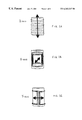
- FIG. 1A illustrates a cylindrical “long solenoid” magnetic coil as one example of a magnetic coil which provides control of a magnetic vector along the z-axis;
- FIG. 1B illustrates a cylindrical “saddle coil pair” as one example of a magnetic coil which provides control of a magnetic vector along the x-axis;
- FIG. 1C illustrates a cylindrical “saddle coil pair” as one example of a magnetic coil which provides control of a magnetic vector along the y-axis;
- FIG. 2 illustrates an energizing coil assembly integrated into a harness as worn by, for instance, a dog
- FIG. 3 illustrates one embodiment of an energizing coil assembly
- FIG. 4 illustrates a region, such as, for instance, a heart having multiple implant sensor devices about its periphery;
- FIG. 5 illustrates one type of inductively powered biomedical implant device geometry suitable for use with the present invention
- FIG. 6 illustrates a second type of inductively powered biomedical implant device geometry suitable for use with the present invention
- FIG. 7 illustrates a simplified block diagram of the magnetic vector steering (MVS) system according to the present invention
- FIG. 8 illustrates a more detailed block diagram of the magnetic vector steering (MVS) system according to the present invention
- FIG. 9 illustrates a simplified schematic of an energizing coil having associated Half-Cycle Amplitude Modulation (HCAM) circuitry according to the present invention
- FIG. 10 illustrates a more detailed circuit schematic of the Half-Cycle Amplitude Modulation (HCAM) system according to the present invention.
- FIG. 11 illustrates a harmonic spectra graph of coil current for varying coil Qs according to the present invention.
- IPT Inductive Power Transfer
- Two approaches have typically been used.
- One common approach is to use multiple energizing coils excited at different frequencies such that the collection of energizing coils possess near orthogonal magnetic vector components.
- Another approach is to use a single energizing coil and multiple, orthogonally-oriented, receiving coils.
- the chief drawback to the former technique is that the multiple energizing coils are unsynchronized in operation (i.e. driven at slightly different frequencies), resulting in a magnetic field spanning in all directions, thus wasting source energy.
- the chief drawback to the latter technique is that an increase in implant (i.e., inductively powered device) volume, and complexity must be afforded due to having multiple receiving coils for each device.
- the Magnetic Vector Steering (MVS) scheme of the present invention uses an energizing coil assembly that supplies power to specific inductively powered devices (stimulators, telemeters, etc.) through the superposition of magnetic fields from separate energizing coils. Unlike previous systems, however, power transfer is not restricted by the orientation of the inductively powered devices, with only a single power-receiving coil. Moreover, the energizing coils are synchronized and therefore operable over the same frequency channel eliminating the problem of having the energizing coil magnetic field propagate inefficiently in all directions. An assembly of external coils is arranged to strategically maneuver a net magnetic field toward a specific inductively powered device within a set of such devices. This technique conserves source energy, since the magnetic vector is kept from wandering in directions where energy transfer to the inductively powered devices is minimal.
- the external coil assembly was chosen to conform to a cylinder integrated into a harness to be worn by an animal.
- the coils that comprise the assembly for this embodiment include a “long solenoid” and two pairs of “saddle coils”. Each of these coils has been shown to exhibit magnetic fields highly uniform both in magnitude and direction throughout the majority of their respective interiors.
- the long solenoid coil illustrated in FIG. 1A provides control of the magnetic vector along the z-axis of the cylinder, while the saddle coils illustrated in FIGS. 1B and 1C provide control in the x-axis and y-axis of the cylinder, respectively.
- FIG. 2 illustrates a harness 20 , as worn by a dog, which includes the coils of FIGS. 1A-C.
- the harness 20 is powered, in this instance, by a battery pack source 22 .
- Other coil types and harnesses may be used in conjunction with the present invention. That is, the combination of two saddle coils and a long solenoid coil described above need not be the only energizing coil implementation. Any coil assembly that can direct a magnetic vector along the x-axis, y-axis, and z-axis will suffice.
- FIG. 3 illustrates a coil assembly which can be integrated with a harness system like the one illustrated in FIG. 2 .
- the coil assembly is a single unit which includes a plurality of separate coils such that the collection of coils is capable of radiating a magnetic field in the x-, y-, and z-axes.
- the present invention is capable of targeting a specific device to provide power to and moving to each device in the set in a prescribed or adaptive pattern.
- FIG. 4 illustrates a sphere 40 which could represent, for instance, the heart of an animal.
- a sphere 40 which could represent, for instance, the heart of an animal.
- the sphere 40 are a plurality of arbitrarily oriented inductively powered coil devices 42 .
- These devices 42 can take the form of biomedical implants which monitor various characteristics of the animal's heart. Upon sufficient coupling with an outside source such as the coil assembly of FIG. 3, these implants will be able to power themselves and even transmit data back to an external receiving device (not shown) for diagnostic processing.
- the system can be programmed with the locations of each implant so the coil assembly can be energized at specific levels such that each implant device is coupled with the energizing coil assembly.
- the program can be “adaptive”, monitoring the energy status of inductively powered devices and scheduling time-slots or dwell times for energy transfer.
- FIGS. 5 and 6 illustrate two examples of inductively powered devices suitable for biomedical implantation applications.
- the implantable device 50 appears key-like in shape and has a reference electrode 52 positioned near the tip of the device 50 .
- a network of sensor sites 54 span the tip and “key” area and are electrically connected to an integrated circuit chip 56 .
- Integrated circuit chip 56 in turn is connected to a coil/antenna 58 which serves to couple with an external energizing coil (not shown) in order to receive power and also to send data out to a receiving device (not shown).
- implantable device 60 is circular in shape having its coil 61 wrapped about the outer periphery of the circular area.
- Telemetry and power conditioning circuitry 62 connects via metal interconnection traces 63 , to coil 61 and signal processing electronics 65 .
- a power supply filtering capacitor or a small battery 66 is shown coupled to the coil 61 .
- the power supply filtering capacitor or a small battery 66 can charge itself and power the implant for a period of time should the external energizing coil (not shown) be temporarily de-activated or de-coupled.
- FIG. 7 A simplified block diagram of the magnetic vector steering system is illustrated in FIG. 7.
- a reference power source 70 is used to provide a stable clock source that generates a power carrier frequency signal.
- the signal from the reference power source 70 is fed to both amplitude control 72 and phase control 74 blocks.
- the output of the amplitude control block 72 is passed to a power amplifier 76 in order to provide sufficient drive capabilities for an energizing coil 78 .
- the energizing coil 78 then sends feedback to both the amplitude 72 and phase 74 control blocks in order to stabilize the system.
- a similar configuration is used for each of the coils that comprise the coil assembly.
- amplitude control ranges over a factor of ten (10), while phase ranges from nearly ⁇ 180° to 180°. Phase shift results while changing the pulse width of the driving waveforms.
- the present invention stabilizes coil currents in both magnitude and phase through the use of two feedback loops.
- One feedback path acts to compensate for magnitude variations through automatic gain control.
- the other feedback path nulls-out phase errors by using a delay-locked loop (DLL).
- DLL delay-locked loop
- Automatic gain control 82 is achieved by detecting the amplitude 84 of a particular energizing coil current and comparing 86 it to a pre-selected value, V m .
- the resulting error term modulates a pulse width of a pulse-width modulator 88 (PWM), thereby changing the amplitude of the first harmonic at its output.
- PWM pulse-width modulator
- the pulse-width modulator drives a Class-D power amplifier 90 , which in turn drives a resonant coil network 92 .
- the magnitude of the output resonant circuit is related to the amount of first harmonic in the PWM power signal. Hence, changes in the amplitude error signal spur counter changes in the amplitude of the resonant coil network 92 .
- a delayed locked-loop corrects for phase shifts by comparing the phase of the reference frequency with that of the coil current.
- Phase error is used to drive a voltage-controlled delay line (VCDL) 104 , thus varying the phase of the PWM input signal, the power driver circuit, and hence, the resonant coil network phase. In this way, changes in the phase error signal bring about counter changes in the resonant coil network phase.
- VCDL voltage-controlled delay line
- this dual-feedback system requires that both feedback mechanisms operate in conjunction with one another without making the system unstable. This is because the gain compensation block 82 uses the output signal from the phase correction block 100 as its input reference frequency.
- the delay locked-loop portion of the phase control block 100 is a familiar block seen in other delay locked-loop applications. It comprises a phase detector 102 , a low-pass filter 106 , and a voltage-controlled delay line (VCDL) 104 . A summation node 108 has also been added in order to allow for user adjustment of the phase.
- VCDL voltage-controlled delay line
- the phase detector 102 most suitable is an XOR-type detector, augmented with lead/lag detection. This type of detector can indicate phase differences from ⁇ pi to +pi radians. Because the output of this detector is comprised of digital logic pulses of varying width, as well as a lead/lag bit, it must be used in conjunction with a low-pass filter 106 that removes the AC component of the XOR output signal. The lead/lag bit controls the polarity of the gain. Under real circumstances, however, a small ripple penetrates the low-pass filter 106 , thus contributing to unmodeled error in the system.
- the output of the phase detector 102 and low-pass filter 106 is fed to a summation node 108 , where a phase offset component can be added.
- a phase offset component can be added.
- Such an input is desirable for setting the bias level of the voltage control delay line (VCDL) 104 that follows, so that VCDL operation can occur at its center or most linear region of operation.
- the voltage-controlled delay line (VCDL) 104 delays the reference signal by a phase that is proportional to an input control voltage.
- the Magnetic Vector Steering (MVS) system described above is capable of powering one or more inductively powered implant devices such as, for instance, certain biomedical implants using a fixed or adaptive scheduling algorithm. If the total energy requirements of a set of implant devices can be met by an energizing coil assembly, then a standard round-robin scheduling method can be employed to inductively power each implant device with the energizing coil assembly dwell time on each implant device being proportional to its energy requirements. Another standard method would be to create fixed energizing coil assembly dwell time segments, and to allocate a number of these specific segments to each implant device.
- Adaptive scheduling may also be used to power the implant devices in cases when the energizing coil assembly can not meet the power needs of all of the implant devices. If each implant device can communicate its stored energy status to the energizing coil assembly, then the implant devices with the highest priority can be scheduled for dwell time on an as needed basis. Such an adaptive scheduling system would be highly effective in applications for which the energy requirements for individual implant devices are time-varying.
- the present invention allows bit transitions to occur up to every half-cycle of the power carrier using a technique known as Half-Cycle Amplitude Modulation (HCAM). This greatly decreases the time required to send command information to, or otherwise communicate with, inductively powered devices.
- HCAM Half-Cycle Amplitude Modulation
- the principle behind half-cycle amplitude modulation is that current can be made to circulate within all or a fractional number of turns of an energizing coil or coils, thus amplitude modulating the magnetic field.
- the circuit dynamics are changed. The removal of a coil section decreases the inductance of the circuit, which in turn shifts the band-pass filter spectra toward infinity.
- the driving frequency no longer coincides with the RLC resonant frequency, and changes in both current amplitude and phase manifest. These changes must also “settle” according to the band-pass characteristics of the RLC network, thus requiring a settling time.
- a nominal inductive link with a 1 MHZ power carrier frequency can support an in-link data transfer rate of 2 Mbps which has not been achieved in prior art systems.
- synchronous AM can be used. Band width limitations of the signal-receiving coil can be eliminated if the coil is not resonated. The voltage gain experienced through resonation is irrelevant in this circumstance due to the inherent strength of the transmitted signal.
- a Class-D amplifier is best suited for this type of application, since it achieves much higher power conversion efficiency than the most efficient linear-type amplifiers (Class-C).
- Class-C linear-type amplifiers
- One drawback, however, of a Class-D amplifier is that harmonic generation is prevalent. Fortunately, the band-pass filtering performed by the resonant energizer-output circuit removes most harmonic content, particularly at much higher frequencies, where it is potentially detrimental due to conflicts with telemeter transmissions.
- Half-cycle amplitude modulation maintains the linear system behavior of the energizing resonant circuits (comprised of an energizing coil and associated resonating capacitor), while instantaneously modulating the amplitude of the emanating magnetic field. This is done by switching-out a section of the energizing coil, while substituting in its place an equivalent inductor that does not contribute magnetic field to the link. The substitution must be accomplished at zero crossings of the coil current when the inductor stored energy is zero.
- FIG. 9 A simplified circuit schematic of the HCAM system is illustrated in FIG. 9.
- a square wave voltage signal 110 is fed through gate drive circuitry 112 and a pair of power MOSFETs 114 .
- the output of the power MOSFETs is sensed and passed through modulation control circuitry 116 before driving a resonant RLC circuit where inductor 118 represents the energizing coil.
- a secondary coil 120 is connected to the energizing coil at a tap point such that the inductance of the secondary coil is equivalent to the tapped out portion of the energizing coil.
- a pair of bi-lateral switches 122 are included, one connected to the energizing coil 118 and the other connected to the secondary coil 120 .
- the switches 122 are also connected to the modulation control circuitry 116 .
- FIG. 10 A more detailed circuit schematic used to implement the HCAM concept is shown in FIG. 10 . It comprises a switch controller (U 1 ), MOSFET driver circuitry (U 2 -U 4 ), and power MOSFETs (M 1 -M 4 ) for coil driving and current steering.
- U 4 is an H-bridge driver chip designed to drive 4 n-channel power MOSFETs.
- Two H-bridge channels are used to drive a half-bridge (M 6 and M 7 ) which in-turn generates the square-wave voltage waveform for the energizing circuit.
- a simple TTL-level clock signal is presented to pin 6 of U 1 for driving the output at the desired frequency.
- Each of the implemented bilateral switches comprise an n-channel and p-channel MOSFET and four diodes.
- the complementary MOSFETs are needed so that current can pass in either direction through the switch.
- diodes D 5 and D 6 act to protect MOSFETs under severe reverse bias conditions.
- Diodes D 1 and D 3 block current from passing through the reverse direction, in the case when a MOSFET is turned off.
- the “LowReturn” switch operates in an identical manner.
- N-channel MOSFETs in the bilateral switches are driven by the two remaining channels of U 1 .
- level shifting In order to drive the p-channel devices, level shifting must be achieved, as they are turned-on by negative voltages.
- the negative driving voltages are generated through a MOSFET driver chip (M 3 ) that is referenced to ⁇ Vss, rather than ground.
- Level-shifted control signals are generated by the multiplexers of U 2 that convert the TTL-level inputs down to ⁇ Vss (low) and 0 volts (high).
- the driving signals are generated by the GAL U 1 .
- the programmed finite-state matching algorithm causes the bilateral switch MOSFETs accordingly.
- the MOSFETs are switched during the half-cycle before they will be used. For example, if a high-to-low transition is to be achieved in the radiated magnetic field, then sometime during the high, positive phase when M 1 is active, M 4 will be turned on. Thus current is steered automatically as the data transitions from high to low. Once current is flowing exclusively through M 4 , M 1 can be turned off (unless it is needed for a “high” signal immediately following the current phase).
- the equation above is comprised of three parts: a DC term, a first harmonic term, and higher-order harmonics.
- a DC term a DC term
- a first harmonic term a harmonic term
- higher-order harmonics a DC term
- the fall-off in harmonic amplitude with respect to frequency is related to 1/(n 2 ⁇ 1). Therefore, harmonic power falls-off even more rapidly as the square of this quantity.
- Low-harmonic content of the power carrier signal at telemeter transmission frequencies is important since implant device transmissions could potentially go undetected due to the overpowering presence of power carrier harmonics.
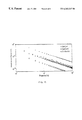
- the higher the Q the more harmonic rejection of the square wave will occur as illustrated in the frequency spectra graphs of FIG. 11 .
- MVS and HCAM are complementary of one another and can be integrated into a single system such as those for biomedical applications.
- MVS Magnetic Vector Steering
- HCAM Half-Cycle Amplitude Modulation
- the preferred embodiment of the present invention is intended for biomedical applications, such as, but not limited to, cardiac mapping. It is, however, suitable for any inductively powered application requiring remote powering of a device and/or data exchange with a remote device. As such, this applies to virtually any situation in which battery-less devices are to operate within a restricted environment.
Abstract
Magnetic Vector Steering (MVS) and Half-Cycle Amplitude Modulation (HCAM) are novel techniques which enhance the powering and control of multiple arbitrarily oriented implant devices. Together, these techniques enable arbitrarily oriented implants to receive power and command, programming, and control information in an efficient manner that preserves battery life and transmission time while reducing overall implant device bulk. By steering the aggregate magnetic field from a near-orthogonal set of AC-energized coils, selected implants can be powered or communicated with at desired times. Communication with individual implants can also be enhanced through half-cycle amplitude modulation—a technique that allows bit rates up to twice the energizing frequency. Unlike prior art systems, power and data transfer can be realized over the same frequency channel.
Description
This application is a division of U.S. patent application Ser. No. 09/094,260, filed Jun. 9, 1998, now U.S. Pat. No. 6,047,214, the disclosure of which is incorporated by reference herein in its entirety.
The present invention relates to techniques for enhancing the powering of and wireless data collection from arbitrarily oriented high-bandwidth remote sensor devices such as inductively powered implant devices.
For the past three decades, biotelemetry has assisted many researchers and clinicians in obtaining physiological information from both patients and animals. With the development of new electronic, communication, battery, and material technologies, the capabilities of biotelemetry systems have expanded, bringing increased performance in the form of longer implantation times, greater channel counts, smaller sizes, and more robust communication.
For a majority of medical applications using biotelemetry implants, it has sufficed to monitor only a few channels of slowly varying DC levels such as pressure, temperature, ion concentration, etc. or small bandwidth signals with bandwidths typically ranging from 100 Hz to 5 kHz per channel such as EKG, EEG, EMG, etc. To date, however, biotelemetry systems have been unable to provide the throughput necessary for certain applications, such as cardiac mapping or high-bandwidth multichannel neural recording in which channel rates in excess of 1 Mbits/sec are often required, thus mandating large amounts of energy to power the implant. For long term studies, the energy requirement becomes even more prohibitive.
Researchers are currently searching for data collection systems that can maximize usage of developing, high-bandwidth sensor systems. Such sensor systems include flexible plastic substrate-based biosensor arrays for biopotential recording, and silicon-based micro-electrode arrays for neural recording.
Also of interest is the ability to collect physiological information from a variety of locations within a subject. This requires a network of sensors placed throughout a region under study. In cardiac mapping, for example, several electropotential arrays may be required at different ischemic or infarcted areas of a heart in order to simultaneously monitor electrical activity during a cardiac event. A desirable implementation for this network has each sensor as a separate telemeter, thereby eliminating the need to interconnect wires among the sensors. The elimination of these wires significantly reduces overall implant bulk and complexity while facilitating implantation.
A fundamental difficulty in developing a high-bandwidth biotelemetry system pertains to implant power consumption. In contrast to low-bandwidth systems, a high-bandwidth system must transmit many more pulses in a given time-period, thus depleting the power source much faster. In addition, the electronics required to sample, process, and encode the sensor data will also draw more energy as the aggregate bandwidth increases. The increased power demands require the use of larger implant batteries or alternative power sources. A popular widely known alternative to relying exclusively on batteries to power an implant is Inductive Power Transfer (IPT).
Inductive Power Transfer uses an AC-energized coil to create a magnetic field that couples with a receiving coil of an inductively powered device. The induced signal appearing at the output of the inductively powered device coil is then rectified and filtered to create a relatively constant DC power source. The “loosely-coupled transformer” link provides a means of eliminating and/or recharging inductively coupled biomedical implant batteries or capacitors. This technique has been used not only for biotelemetry devices, but also for artificial hearts, ventricular assist devices, various forms of neural stimulators, and battery recharging.
What is needed is a system which can accurately target arbitrarily oriented inductively powered devices in order to provide power to, and communicate at high data rates with, the arbitrarily oriented inductively powered devices.
The present invention pertains to a system capable of high-bandwidth communication and omnidirectional power transfer to a network of arbitrarily positioned inductively powered devices. Magnetic Vector Steering (MVS) and Half-Cycle Amplitude Modulation (HCAM) are two novel techniques which enhance the powering and control of multiple inductively powered devices. Together, these techniques enable arbitrarily oriented inductively powered devices to receive power and command/programming/control information in an efficient manner that preserves battery life and transmission time. By directing the aggregate magnetic field, using magnetic vector steering, from a near-orthogonal set of AC-energizing coils, selected inductively powered devices can be powered and/or communicated with at desired times. Communication with individual inductively powered devices can also be enhanced through half-cycle amplitude modulation—a technique that allows bit rate transfers up to twice the energizing frequency. The present invention combines power and data transmission circuitry more effectively than the prior art while also significantly reducing the hardware required of an inductively powered device such as a biomedical implant thereby reducing overall implant bulk.
It is an object of the present invention to provide a system for remotely powering one or more inductively powered devices such that the overall bulk of such devices is significantly reduced.
It is a further object of the present invention to provide a data communication system which can modulate a power carrier, communicating with one or more inductively powered devices, with a serial data stream at up to twice the cycle rate of the power carrier.
It is a still further object of the invention to allow the use of a single frequency channel for both power and data transfer to arbitrarily oriented inductively powered devices.
Some of the objects of the invention having been stated, other objects will become apparent as the description proceeds, when taken in connection with the accompanying drawings described as follows:
FIG. 1A illustrates a cylindrical “long solenoid” magnetic coil as one example of a magnetic coil which provides control of a magnetic vector along the z-axis;
FIG. 1B illustrates a cylindrical “saddle coil pair” as one example of a magnetic coil which provides control of a magnetic vector along the x-axis;
FIG. 1C illustrates a cylindrical “saddle coil pair” as one example of a magnetic coil which provides control of a magnetic vector along the y-axis;
FIG. 2 illustrates an energizing coil assembly integrated into a harness as worn by, for instance, a dog;
FIG. 3 illustrates one embodiment of an energizing coil assembly;
FIG. 4 illustrates a region, such as, for instance, a heart having multiple implant sensor devices about its periphery;
FIG. 5 illustrates one type of inductively powered biomedical implant device geometry suitable for use with the present invention;
FIG. 6 illustrates a second type of inductively powered biomedical implant device geometry suitable for use with the present invention;
FIG. 7 illustrates a simplified block diagram of the magnetic vector steering (MVS) system according to the present invention;
FIG. 8 illustrates a more detailed block diagram of the magnetic vector steering (MVS) system according to the present invention;
FIG. 9 illustrates a simplified schematic of an energizing coil having associated Half-Cycle Amplitude Modulation (HCAM) circuitry according to the present invention;
FIG. 10 illustrates a more detailed circuit schematic of the Half-Cycle Amplitude Modulation (HCAM) system according to the present invention; and
FIG. 11 illustrates a harmonic spectra graph of coil current for varying coil Qs according to the present invention.
The present invention is described more fully hereinafter with reference to the aforementioned drawings, in which preferred embodiments of the invention are shown. This invention may, however, be embodied in many different forms and should not be construed as limited to the embodiments set forth herein.
Although inductive links such as Inductive Power Transfer (IPT) have been used extensively for both powering of and communication with inductively powered devices, there are several limitations with respect to their use. When multiple and/or arbitrarily positioned inductively powered devices are energized by an external coil(s), a burdensome diversity scheme is required to ensure that a sufficient degree of magnetic coupling exists between the external “energizing” coil(s) and the inductively powered device coil(s).
Two approaches have typically been used. One common approach is to use multiple energizing coils excited at different frequencies such that the collection of energizing coils possess near orthogonal magnetic vector components. Another approach is to use a single energizing coil and multiple, orthogonally-oriented, receiving coils.
The chief drawback to the former technique is that the multiple energizing coils are unsynchronized in operation (i.e. driven at slightly different frequencies), resulting in a magnetic field spanning in all directions, thus wasting source energy. The chief drawback to the latter technique is that an increase in implant (i.e., inductively powered device) volume, and complexity must be afforded due to having multiple receiving coils for each device.
The Magnetic Vector Steering (MVS) scheme of the present invention uses an energizing coil assembly that supplies power to specific inductively powered devices (stimulators, telemeters, etc.) through the superposition of magnetic fields from separate energizing coils. Unlike previous systems, however, power transfer is not restricted by the orientation of the inductively powered devices, with only a single power-receiving coil. Moreover, the energizing coils are synchronized and therefore operable over the same frequency channel eliminating the problem of having the energizing coil magnetic field propagate inefficiently in all directions. An assembly of external coils is arranged to strategically maneuver a net magnetic field toward a specific inductively powered device within a set of such devices. This technique conserves source energy, since the magnetic vector is kept from wandering in directions where energy transfer to the inductively powered devices is minimal.
In one exemplary embodiment, the external coil assembly was chosen to conform to a cylinder integrated into a harness to be worn by an animal. The coils that comprise the assembly for this embodiment include a “long solenoid” and two pairs of “saddle coils”. Each of these coils has been shown to exhibit magnetic fields highly uniform both in magnitude and direction throughout the majority of their respective interiors. The long solenoid coil illustrated in FIG. 1A provides control of the magnetic vector along the z-axis of the cylinder, while the saddle coils illustrated in FIGS. 1B and 1C provide control in the x-axis and y-axis of the cylinder, respectively.
FIG. 2 illustrates a harness 20, as worn by a dog, which includes the coils of FIGS. 1A-C. The harness 20 is powered, in this instance, by a battery pack source 22. Other coil types and harnesses, however, may be used in conjunction with the present invention. That is, the combination of two saddle coils and a long solenoid coil described above need not be the only energizing coil implementation. Any coil assembly that can direct a magnetic vector along the x-axis, y-axis, and z-axis will suffice.
FIG. 3 illustrates a coil assembly which can be integrated with a harness system like the one illustrated in FIG. 2. The coil assembly is a single unit which includes a plurality of separate coils such that the collection of coils is capable of radiating a magnetic field in the x-, y-, and z-axes. By varying the energy supplied to each coil, the magnitude and direction of the resulting magnetic field vector can be controlled. Using this technique together with knowledge of the orientation of a set of inductively powered devices, the present invention is capable of targeting a specific device to provide power to and moving to each device in the set in a prescribed or adaptive pattern.
FIG. 4 illustrates a sphere 40 which could represent, for instance, the heart of an animal. About the sphere 40 are a plurality of arbitrarily oriented inductively powered coil devices 42. These devices 42 can take the form of biomedical implants which monitor various characteristics of the animal's heart. Upon sufficient coupling with an outside source such as the coil assembly of FIG. 3, these implants will be able to power themselves and even transmit data back to an external receiving device (not shown) for diagnostic processing. The system can be programmed with the locations of each implant so the coil assembly can be energized at specific levels such that each implant device is coupled with the energizing coil assembly. The program can be “adaptive”, monitoring the energy status of inductively powered devices and scheduling time-slots or dwell times for energy transfer.
FIGS. 5 and 6 illustrate two examples of inductively powered devices suitable for biomedical implantation applications. Referring now to FIG. 5, the implantable device 50 appears key-like in shape and has a reference electrode 52 positioned near the tip of the device 50. A network of sensor sites 54 span the tip and “key” area and are electrically connected to an integrated circuit chip 56. Integrated circuit chip 56 in turn is connected to a coil/antenna 58 which serves to couple with an external energizing coil (not shown) in order to receive power and also to send data out to a receiving device (not shown). Referring now to FIG. 6, implantable device 60 is circular in shape having its coil 61 wrapped about the outer periphery of the circular area. Telemetry and power conditioning circuitry 62 connects via metal interconnection traces 63, to coil 61 and signal processing electronics 65. Lastly, a power supply filtering capacitor or a small battery 66 is shown coupled to the coil 61. The power supply filtering capacitor or a small battery 66 can charge itself and power the implant for a period of time should the external energizing coil (not shown) be temporarily de-activated or de-coupled.
A simplified block diagram of the magnetic vector steering system is illustrated in FIG. 7. A reference power source 70 is used to provide a stable clock source that generates a power carrier frequency signal. The signal from the reference power source 70 is fed to both amplitude control 72 and phase control 74 blocks. The output of the amplitude control block 72 is passed to a power amplifier 76 in order to provide sufficient drive capabilities for an energizing coil 78. The energizing coil 78 then sends feedback to both the amplitude 72 and phase 74 control blocks in order to stabilize the system. A similar configuration is used for each of the coils that comprise the coil assembly.
For the present magnetic vector steering (MVS) system, amplitude control ranges over a factor of ten (10), while phase ranges from nearly −180° to 180°. Phase shift results while changing the pulse width of the driving waveforms.
Referring now to FIG. 8, popular compensation techniques such as those described below are either undesirable or impractical for the present invention. Altering the driver reference frequency will not accommodate variations in resonant frequencies of all coil circuits, both external and implanted. Tuning diodes (varactors) are undesirable, since they are highly non-linear over large voltage swings and their biasing is impractical. Likewise, transductor-based compensation is also undesirable on account of similar non-linearity problems as well as increased weight, size, and power consumption (a strong DC current is required to alter a transductors inductance).
The present invention, however, stabilizes coil currents in both magnitude and phase through the use of two feedback loops. One feedback path acts to compensate for magnitude variations through automatic gain control. The other feedback path nulls-out phase errors by using a delay-locked loop (DLL).
With regard to the phase compensation circuit 100, a delayed locked-loop (DLL) corrects for phase shifts by comparing the phase of the reference frequency with that of the coil current. Phase error is used to drive a voltage-controlled delay line (VCDL) 104, thus varying the phase of the PWM input signal, the power driver circuit, and hence, the resonant coil network phase. In this way, changes in the phase error signal bring about counter changes in the resonant coil network phase.
As shown in FIG. 8, this dual-feedback system requires that both feedback mechanisms operate in conjunction with one another without making the system unstable. This is because the gain compensation block 82 uses the output signal from the phase correction block 100 as its input reference frequency.
The delay locked-loop portion of the phase control block 100 is a familiar block seen in other delay locked-loop applications. It comprises a phase detector 102, a low-pass filter 106, and a voltage-controlled delay line (VCDL) 104. A summation node 108 has also been added in order to allow for user adjustment of the phase.
The phase detector 102 most suitable is an XOR-type detector, augmented with lead/lag detection. This type of detector can indicate phase differences from −pi to +pi radians. Because the output of this detector is comprised of digital logic pulses of varying width, as well as a lead/lag bit, it must be used in conjunction with a low-pass filter 106 that removes the AC component of the XOR output signal. The lead/lag bit controls the polarity of the gain. Under real circumstances, however, a small ripple penetrates the low-pass filter 106, thus contributing to unmodeled error in the system.
The output of the phase detector 102 and low-pass filter 106 is fed to a summation node 108, where a phase offset component can be added. Such an input is desirable for setting the bias level of the voltage control delay line (VCDL) 104 that follows, so that VCDL operation can occur at its center or most linear region of operation. The voltage-controlled delay line (VCDL) 104 delays the reference signal by a phase that is proportional to an input control voltage.
The Magnetic Vector Steering (MVS) system described above is capable of powering one or more inductively powered implant devices such as, for instance, certain biomedical implants using a fixed or adaptive scheduling algorithm. If the total energy requirements of a set of implant devices can be met by an energizing coil assembly, then a standard round-robin scheduling method can be employed to inductively power each implant device with the energizing coil assembly dwell time on each implant device being proportional to its energy requirements. Another standard method would be to create fixed energizing coil assembly dwell time segments, and to allocate a number of these specific segments to each implant device.
Adaptive scheduling may also be used to power the implant devices in cases when the energizing coil assembly can not meet the power needs of all of the implant devices. If each implant device can communicate its stored energy status to the energizing coil assembly, then the implant devices with the highest priority can be scheduled for dwell time on an as needed basis. Such an adaptive scheduling system would be highly effective in applications for which the energy requirements for individual implant devices are time-varying.
Another limitation of prior art inductively powered link systems is the limited bandwidth of the energizing coils. Ordinarily, medium-Q to high-Q coils are resonated to maximize coupling efficiency and remove undesired harmonics. The Q of a coil represents the resonant peak of circuit response. Narrowband coils, however, restrict the communication rate of the link, due to the increase in response time with coil Q. For example, it can be easily shown that for the magnitude of an energizing coil current to settle within 5% of its final value (indicative of a complete bit transition in AM), it would take a number of cycles of the power carrier roughly equal to the Q of the coil. Hence for a nominal energizing coil Q of 50, fifty power carrier cycles would be required to register a bit transition. This response time can greatly reduce system throughput if inductively powered devices are required to transmit information upon command of the external energizing coil assembly.
The present invention, however, allows bit transitions to occur up to every half-cycle of the power carrier using a technique known as Half-Cycle Amplitude Modulation (HCAM). This greatly decreases the time required to send command information to, or otherwise communicate with, inductively powered devices.
The principle behind half-cycle amplitude modulation is that current can be made to circulate within all or a fractional number of turns of an energizing coil or coils, thus amplitude modulating the magnetic field. However, when a portion of the coil is instantaneously removed or switched out from the RLC circuit, the circuit dynamics are changed. The removal of a coil section decreases the inductance of the circuit, which in turn shifts the band-pass filter spectra toward infinity. As a result, the driving frequency no longer coincides with the RLC resonant frequency, and changes in both current amplitude and phase manifest. These changes must also “settle” according to the band-pass characteristics of the RLC network, thus requiring a settling time.
If, however, an inductor with equivalent impedance (both real and imaginary) to the removed section is substituted or switched in for the removed section, the circuit dynamics will remain the same. The key to the substitution (or switching) is to perform it at a strategic instant when it can be made undetectably. In this way, there are no step changes in network dynamics experienced by the RLC network; hence, there is no time lost to transition recovery.
The instant to switch the inductors would be when the inductor current is zero. This occurs twice during a given cycle of the power carrier; hence, it becomes possible to transmit two bits of data per cycle. A nominal inductive link with a 1 MHZ power carrier frequency can support an in-link data transfer rate of 2 Mbps which has not been achieved in prior art systems.
To recover the power carrier signal, synchronous AM can be used. Band width limitations of the signal-receiving coil can be eliminated if the coil is not resonated. The voltage gain experienced through resonation is irrelevant in this circumstance due to the inherent strength of the transmitted signal.
A Class-D amplifier is best suited for this type of application, since it achieves much higher power conversion efficiency than the most efficient linear-type amplifiers (Class-C). One drawback, however, of a Class-D amplifier is that harmonic generation is prevalent. Fortunately, the band-pass filtering performed by the resonant energizer-output circuit removes most harmonic content, particularly at much higher frequencies, where it is potentially detrimental due to conflicts with telemeter transmissions.
Half-cycle amplitude modulation maintains the linear system behavior of the energizing resonant circuits (comprised of an energizing coil and associated resonating capacitor), while instantaneously modulating the amplitude of the emanating magnetic field. This is done by switching-out a section of the energizing coil, while substituting in its place an equivalent inductor that does not contribute magnetic field to the link. The substitution must be accomplished at zero crossings of the coil current when the inductor stored energy is zero.
A simplified circuit schematic of the HCAM system is illustrated in FIG. 9. A square wave voltage signal 110 is fed through gate drive circuitry 112 and a pair of power MOSFETs 114. The output of the power MOSFETs is sensed and passed through modulation control circuitry 116 before driving a resonant RLC circuit where inductor 118 represents the energizing coil. A secondary coil 120 is connected to the energizing coil at a tap point such that the inductance of the secondary coil is equivalent to the tapped out portion of the energizing coil. A pair of bi-lateral switches 122 are included, one connected to the energizing coil 118 and the other connected to the secondary coil 120. The switches 122 are also connected to the modulation control circuitry 116.
A more detailed circuit schematic used to implement the HCAM concept is shown in FIG. 10. It comprises a switch controller (U1), MOSFET driver circuitry (U2-U4), and power MOSFETs (M1-M4) for coil driving and current steering. U4 is an H-bridge driver chip designed to drive 4 n-channel power MOSFETs. Two H-bridge channels are used to drive a half-bridge (M6 and M7) which in-turn generates the square-wave voltage waveform for the energizing circuit. A simple TTL-level clock signal is presented to pin 6 of U1 for driving the output at the desired frequency. Each of the implemented bilateral switches comprise an n-channel and p-channel MOSFET and four diodes. The complementary MOSFETs are needed so that current can pass in either direction through the switch. With respect to the left-most switch (indicated by the signal “HighReturn”), diodes D5 and D6 act to protect MOSFETs under severe reverse bias conditions. Diodes D1 and D3 block current from passing through the reverse direction, in the case when a MOSFET is turned off. The “LowReturn” switch operates in an identical manner.
N-channel MOSFETs in the bilateral switches are driven by the two remaining channels of U1. In order to drive the p-channel devices, level shifting must be achieved, as they are turned-on by negative voltages. The negative driving voltages are generated through a MOSFET driver chip (M3) that is referenced to −Vss, rather than ground. Level-shifted control signals are generated by the multiplexers of U2 that convert the TTL-level inputs down to −Vss (low) and 0 volts (high).
The driving signals are generated by the GAL U1. When presented with the phase polarity of the energizing current waveform, a data bit, and a clocking signal (derived from the energizing-current waveform), the programmed finite-state matching algorithm causes the bilateral switch MOSFETs accordingly. To avoid the need for exact switch timing, the MOSFETs are switched during the half-cycle before they will be used. For example, if a high-to-low transition is to be achieved in the radiated magnetic field, then sometime during the high, positive phase when M1 is active, M4 will be turned on. Thus current is steered automatically as the data transitions from high to low. Once current is flowing exclusively through M4, M1 can be turned off (unless it is needed for a “high” signal immediately following the current phase).
For the ideal case of a sinusoid alternating between two magnitudes (A1 and A2) every half cycle, one can obtain the frequency spectra according to the following: 
The equation above is comprised of three parts: a DC term, a first harmonic term, and higher-order harmonics. One should note the fall-off in harmonic amplitude with respect to frequency is related to 1/(n2−1). Therefore, harmonic power falls-off even more rapidly as the square of this quantity. Low-harmonic content of the power carrier signal at telemeter transmission frequencies is important since implant device transmissions could potentially go undetected due to the overpowering presence of power carrier harmonics. The higher the Q the more harmonic rejection of the square wave will occur as illustrated in the frequency spectra graphs of FIG. 11.
The foregoing descriptions of MVS and HCAM are complementary of one another and can be integrated into a single system such as those for biomedical applications. In cardiac mapping, for instance, Magnetic Vector Steering (MVS) can be used to provide power to and communicate with biomedical implants placed in regions of interest about the heart of a patient such as ischemic or infarcted areas. Half-Cycle Amplitude Modulation (HCAM) can then be used to communicate at higher bandwidth data rates with the biomedical implants powered under MVS.
The preferred embodiment of the present invention is intended for biomedical applications, such as, but not limited to, cardiac mapping. It is, however, suitable for any inductively powered application requiring remote powering of a device and/or data exchange with a remote device. As such, this applies to virtually any situation in which battery-less devices are to operate within a restricted environment.
In the claims, means-plus-function clauses, to the extent they are recited, are intended to cover the structures described herein as performing the recited function and not only structural equivalents but also equivalent structures. Therefore, it is to be understood that the foregoing is illustrative of the present invention and is not to be construed as limited to the specific embodiments disclosed, and that modifications to the disclosed embodiments, as well as other embodiments, are intended to be included within the scope of the appended claims. The invention is defined by the following claims, with equivalents of the claims to be included therein.
Claims (4)
1. A system for inductively powering, controlling, and communicating with a plurality of biomedical implants comprising:
(a) a plurality of inductively powered biomedical implants positioned about a region of interest;
(b) an external coil assembly for the purpose of directing a magnetic field toward an implant of interest; and
(c) half-cycle amplitude modulation means coupled to said external coil assembly for transmitting data at up to twice the coil assembly power carrier frequency;
wherein said external coil assembly targets individual inductively powered implants using a steerable magnetic vector to direct the magnetic field of the energizing coil assembly to the inductively powered implant of interest.
2. The system of claim 1 wherein said external coil assembly comprises:
(a) an energizing coil for inductively powering said implants;
(b) magnetic field sensing means coupled to said energizing coil for determining the strength and phase of said energizing coil's magnetic field;
(c) a pulse width modulation phasing circuit having:
(i) gain compensation means for maintaining a prescribed current within said energizing coil; and
(ii) phase compensation means for maintaining a fixed phase delay between said energizing coil and a clock source; and
(d) a power amplifier coupled to said pulse width modulation phasing circuit for amplifying the pulse width modulation phasing circuit output signal in order to drive said energizing coil.
3. The system of claim 2 wherein one or more energizing coils are linked together such that said implants may be arbitrarily oriented about said region of interest, and are powered by said one or more energizing coils at the same frequency and phase or phase ±II.
4. The system of claim 3 wherein said half-cycle amplitude modulation means comprises:
(a) an energizing circuit comprised of said energizing coil coupled to a resonating capacitance driven by an AC power source, wherein said energizing coil is tap-able;
(b) a second inductive coil coupled to a tap point on the tap-able energizing coil, said second inductive coil having an effective inductance equivalent to a tapped section of the tap-able energizing coil;
(c) a first bi-lateral switch coupled to the tap-able energizing coil;
(d) a second bi-lateral switch coupled to the second inductive coil;
(e) modulation control means coupled to said switches for current steering; and
(f) current sensing means coupled to said modulation control means for detecting zero crossings of the energizing current waveform, such that bit transitions occur with every half-cycle of a power carrier reference signal when the magnetic field is modulated at instants when the energizing coil current is zero.
Priority Applications (1)
| Application Number | Priority Date | Filing Date | Title |
|---|---|---|---|
| US09/436,680 US6263247B1 (en) | 1998-06-09 | 1999-11-09 | System and method for powering, controlling, and communicating with multiple inductively-powered devices |
Applications Claiming Priority (2)
| Application Number | Priority Date | Filing Date | Title |
|---|---|---|---|
| US09/094,260 US6047214A (en) | 1998-06-09 | 1998-06-09 | System and method for powering, controlling, and communicating with multiple inductively-powered devices |
| US09/436,680 US6263247B1 (en) | 1998-06-09 | 1999-11-09 | System and method for powering, controlling, and communicating with multiple inductively-powered devices |
Related Parent Applications (1)
| Application Number | Title | Priority Date | Filing Date |
|---|---|---|---|
| US09/094,260 Division US6047214A (en) | 1998-06-09 | 1998-06-09 | System and method for powering, controlling, and communicating with multiple inductively-powered devices |
Publications (1)
| Publication Number | Publication Date |
|---|---|
| US6263247B1 true US6263247B1 (en) | 2001-07-17 |
Family
ID=22244085
Family Applications (3)
| Application Number | Title | Priority Date | Filing Date |
|---|---|---|---|
| US09/094,260 Expired - Lifetime US6047214A (en) | 1998-06-09 | 1998-06-09 | System and method for powering, controlling, and communicating with multiple inductively-powered devices |
| US09/436,680 Expired - Lifetime US6263247B1 (en) | 1998-06-09 | 1999-11-09 | System and method for powering, controlling, and communicating with multiple inductively-powered devices |
| US09/436,674 Expired - Lifetime US6345203B1 (en) | 1998-06-09 | 1999-11-09 | System and method for powering, controlling, and communicating with multiple inductively-powered devices |
Family Applications Before (1)
| Application Number | Title | Priority Date | Filing Date |
|---|---|---|---|
| US09/094,260 Expired - Lifetime US6047214A (en) | 1998-06-09 | 1998-06-09 | System and method for powering, controlling, and communicating with multiple inductively-powered devices |
Family Applications After (1)
| Application Number | Title | Priority Date | Filing Date |
|---|---|---|---|
| US09/436,674 Expired - Lifetime US6345203B1 (en) | 1998-06-09 | 1999-11-09 | System and method for powering, controlling, and communicating with multiple inductively-powered devices |
Country Status (1)
| Country | Link |
|---|---|
| US (3) | US6047214A (en) |
Cited By (50)
| Publication number | Priority date | Publication date | Assignee | Title |
|---|---|---|---|---|
| US6443891B1 (en) * | 2000-09-20 | 2002-09-03 | Medtronic, Inc. | Telemetry modulation protocol system for medical devices |
| US20020165592A1 (en) * | 2001-04-04 | 2002-11-07 | Arkady Glukhovsky | Induction powered in vivo imaging device |
| US20030015479A1 (en) * | 1999-06-21 | 2003-01-23 | Kuennen Roy W. | Inductively coupled ballast circuit |
| US20030214255A1 (en) * | 1999-06-21 | 2003-11-20 | Baarman David W. | Inductively powered apparatus |
| US20040116981A1 (en) * | 2002-12-13 | 2004-06-17 | Cardiac Pacemakers, Inc. | Device communications of an implantable medical device and an external system |
| US20040122488A1 (en) * | 2002-12-23 | 2004-06-24 | Cardiac Pacemakers, Inc. | Method and apparatus for enabling data communication between an implantable medical device and a patient management system |
| US20040122489A1 (en) * | 2002-12-23 | 2004-06-24 | Cardiac Pacemakers, Inc. | Implantable medical device having long-term wireless capabilities |
| US20040128161A1 (en) * | 2002-12-27 | 2004-07-01 | Mazar Scott T. | System and method for ad hoc communications with an implantable medical device |
| WO2005109598A1 (en) * | 2004-05-11 | 2005-11-17 | Splashpower Limited | Controlling inductive power transfer systems |
| US6978182B2 (en) | 2002-12-27 | 2005-12-20 | Cardiac Pacemakers, Inc. | Advanced patient management system including interrogator/transceiver unit |
| US7009511B2 (en) | 2002-12-17 | 2006-03-07 | Cardiac Pacemakers, Inc. | Repeater device for communications with an implantable medical device |
| US20060089592A1 (en) * | 2004-10-21 | 2006-04-27 | Cardiac Pacemakers, Inc. | Systems and methods for drug therapy enhancement using expected pharmacodynamic models |
| US20060087282A1 (en) * | 2004-10-27 | 2006-04-27 | Baarman David W | Implement rack and system for energizing implements |
| US20070011028A1 (en) * | 2005-07-05 | 2007-01-11 | Cardiac Pacemakers, Inc. | Optimization of timing for data collection and analysis in advanced patient management system |
| US20070085487A1 (en) * | 1999-06-21 | 2007-04-19 | Access Business Group International Llc | Inductively Coupled Ballast Circuit |
| US20070248119A1 (en) * | 1999-10-28 | 2007-10-25 | Koji Takeguchi | Transmission system |
| US20090001941A1 (en) * | 2007-06-29 | 2009-01-01 | Microsoft Corporation | Inductive Powering Surface for Powering Portable Devices |
| US20090157150A1 (en) * | 2007-11-26 | 2009-06-18 | Microtransponder Inc. | Implanted Driver with Resistive Charge Balancing |
| US20090198293A1 (en) * | 2003-12-19 | 2009-08-06 | Lawrence Cauller | Microtransponder Array for Implant |
| US20090210035A1 (en) * | 2008-02-20 | 2009-08-20 | Daniel Gelbart | System for powering medical implants |
| US20090286476A1 (en) * | 2008-05-13 | 2009-11-19 | Qualcomm Incorporated | Reverse link signaling via receive antenna impedance modulation |
| US20100004705A1 (en) * | 2008-07-02 | 2010-01-07 | Microtransponder Inc. | Systems, Methods and Devices for Treating Tinnitus |
| US20100010565A1 (en) * | 2008-07-09 | 2010-01-14 | Samuel Victor Lichtenstein | Extended range wireless muscular and neural stimulation |
| US20100022908A1 (en) * | 2003-12-19 | 2010-01-28 | Board Of Regents, The University Of Texas System | System and Method for Interfacing Cellular Matter with a Machine |
| AU2004260109B2 (en) * | 2003-07-22 | 2010-01-28 | Flexcon Industries | Expansion tank with double diaphragm |
| US20100069994A1 (en) * | 2007-06-25 | 2010-03-18 | Microtransponder, Inc. | Methods of inducing paresthesia using wireless neurostimulation |
| US7794499B2 (en) | 2004-06-08 | 2010-09-14 | Theken Disc, L.L.C. | Prosthetic intervertebral spinal disc with integral microprocessor |
| US8115635B2 (en) | 2005-02-08 | 2012-02-14 | Abbott Diabetes Care Inc. | RF tag on test strips, test strip vials and boxes |
| US8457757B2 (en) | 2007-11-26 | 2013-06-04 | Micro Transponder, Inc. | Implantable transponder systems and methods |
| US8594806B2 (en) | 2010-04-30 | 2013-11-26 | Cyberonics, Inc. | Recharging and communication lead for an implantable device |
| US8634927B2 (en) | 2011-01-28 | 2014-01-21 | Medtronic, Inc. | Medical device recharge systems using a controller in wireless communication with a separate recharge device |
| US8674557B2 (en) | 2010-04-08 | 2014-03-18 | Samsung Electronics Co., Ltd. | Resonance power generation apparatus |
| US8712541B2 (en) | 2011-01-28 | 2014-04-29 | Medtronic, Inc. | Far field telemetry operations between an external device and an implantable medical device during recharge of the implantable medical device via a proximity coupling |
| US8854224B2 (en) | 2009-02-10 | 2014-10-07 | Qualcomm Incorporated | Conveying device information relating to wireless charging |
| US8878393B2 (en) | 2008-05-13 | 2014-11-04 | Qualcomm Incorporated | Wireless power transfer for vehicles |
| US20150016163A1 (en) * | 2013-07-11 | 2015-01-15 | Infineon Technologies Austria Ag | Detector and a voltage converter |
| AU2013206118B2 (en) * | 2009-02-10 | 2015-07-23 | Boston Scientific Neuromodulation Corporation | External device for communicating with an implantable medical device having data telemetry and charging integrated in a single housing |
| US9312924B2 (en) | 2009-02-10 | 2016-04-12 | Qualcomm Incorporated | Systems and methods relating to multi-dimensional wireless charging |
| US9583953B2 (en) | 2009-02-10 | 2017-02-28 | Qualcomm Incorporated | Wireless power transfer for portable enclosures |
| US9730764B2 (en) | 2015-10-02 | 2017-08-15 | Elucent Medical, Inc. | Signal tag detection components, devices, and systems |
| US9855376B2 (en) | 2014-07-25 | 2018-01-02 | Minnetronix, Inc. | Power scaling |
| US9987097B2 (en) | 2015-10-02 | 2018-06-05 | Elucent Medical, Inc. | Signal tag detection components, devices, and systems |
| US10149933B2 (en) | 2014-07-25 | 2018-12-11 | Minnetronix, Inc. | Coil parameters and control |
| US10154799B2 (en) | 2016-08-12 | 2018-12-18 | Elucent Medical, Inc. | Surgical device guidance and monitoring devices, systems, and methods |
| US10193395B2 (en) | 2015-04-14 | 2019-01-29 | Minnetronix, Inc. | Repeater resonator |
| US10278779B1 (en) | 2018-06-05 | 2019-05-07 | Elucent Medical, Inc. | Exciter assemblies |
| US10286217B2 (en) | 2011-01-28 | 2019-05-14 | Medtronic, Inc. | Far field telemetry communication with a medical device during a recharge session where a prior pairing with the medical device may not exist |
| US10342908B2 (en) | 2015-01-14 | 2019-07-09 | Minnetronix, Inc. | Distributed transformer |
| US10406267B2 (en) | 2015-01-16 | 2019-09-10 | Minnetronix, Inc. | Data communication in a transcutaneous energy transfer system |
| US11344382B2 (en) | 2014-01-24 | 2022-05-31 | Elucent Medical, Inc. | Systems and methods comprising localization agents |
Families Citing this family (175)
| Publication number | Priority date | Publication date | Assignee | Title |
|---|---|---|---|---|
| US6047214A (en) * | 1998-06-09 | 2000-04-04 | North Carolina State University | System and method for powering, controlling, and communicating with multiple inductively-powered devices |
| US6402689B1 (en) * | 1998-09-30 | 2002-06-11 | Sicel Technologies, Inc. | Methods, systems, and associated implantable devices for dynamic monitoring of physiological and biological properties of tumors |
| US6212430B1 (en) * | 1999-05-03 | 2001-04-03 | Abiomed, Inc. | Electromagnetic field source with detection of position of secondary coil in relation to multiple primary coils |
| US7522878B2 (en) * | 1999-06-21 | 2009-04-21 | Access Business Group International Llc | Adaptive inductive power supply with communication |
| US6458164B1 (en) * | 2000-04-25 | 2002-10-01 | The Penn State Research Foundation | Artificial heart with energy recovery |
| JP2004505748A (en) | 2000-08-23 | 2004-02-26 | ミクロニックス ピーティーワイ リミテッド | Catheter position display device and use thereof |
| US6591139B2 (en) | 2000-09-06 | 2003-07-08 | Advanced Bionics Corporation | Low-power, high-modulation-index amplifier for use in battery-powered device |
| EP1339312B1 (en) * | 2000-10-10 | 2006-01-04 | Microchips, Inc. | Microchip reservoir devices using wireless transmission of power and data |
| AU2002224453A1 (en) | 2000-10-11 | 2002-04-22 | Microchips, Inc. | Microchip reservoir devices and facilitated corrosion of electrodes |
| ATE441110T1 (en) * | 2000-11-09 | 2009-09-15 | Sicel Technologies Inc | IN-VIVO DETECTION OF BIOMOLECULE CONCENTRATIONS USING FLUORESCENCE MARKERS |
| JP4657577B2 (en) | 2001-01-09 | 2011-03-23 | マイクロチップス・インコーポレーテッド | Flexible microchip device for ocular and other applications |
| US6993669B2 (en) | 2001-04-18 | 2006-01-31 | Gallitzin Allegheny Llc | Low power clocking systems and methods |
| US6990598B2 (en) * | 2001-03-21 | 2006-01-24 | Gallitzin Allegheny Llc | Low power reconfigurable systems and methods |
| US7011814B2 (en) * | 2001-04-23 | 2006-03-14 | Sicel Technologies, Inc. | Systems, methods and devices for in vivo monitoring of a localized response via a radiolabeled analyte in a subject |
| US7057518B2 (en) | 2001-06-22 | 2006-06-06 | Schmidt Dominik J | Systems and methods for testing wireless devices |
| US6898721B2 (en) | 2001-06-22 | 2005-05-24 | Gallitzin Allegheny Llc | Clock generation systems and methods |
| US7557353B2 (en) * | 2001-11-30 | 2009-07-07 | Sicel Technologies, Inc. | Single-use external dosimeters for use in radiation therapies |
| AU2003209287A1 (en) | 2002-01-15 | 2003-07-30 | The Regents Of The University Of California | System and method providing directional ultrasound therapy to skeletal joints |
| US7819826B2 (en) | 2002-01-23 | 2010-10-26 | The Regents Of The University Of California | Implantable thermal treatment method and apparatus |
| DE10218124B4 (en) * | 2002-04-23 | 2004-07-15 | Siemens Ag | Charger for contactless charging of battery-operated devices |
| US7254449B2 (en) * | 2002-07-31 | 2007-08-07 | Advanced Bionics Corp | Systems and methods for providing power to one or more implantable devices |
| US6907884B2 (en) | 2002-09-30 | 2005-06-21 | Depay Acromed, Inc. | Method of straddling an intraosseous nerve |
| US8361067B2 (en) | 2002-09-30 | 2013-01-29 | Relievant Medsystems, Inc. | Methods of therapeutically heating a vertebral body to treat back pain |
| US7258690B2 (en) | 2003-03-28 | 2007-08-21 | Relievant Medsystems, Inc. | Windowed thermal ablation probe |
| US20050256549A1 (en) * | 2002-10-09 | 2005-11-17 | Sirius Implantable Systems Ltd. | Micro-generator implant |
| US8183827B2 (en) * | 2003-01-28 | 2012-05-22 | Hewlett-Packard Development Company, L.P. | Adaptive charger system and method |
| JP4607859B2 (en) * | 2003-02-19 | 2011-01-05 | サイセル・テクノロジーズ,インコーポレイテッド | In vivo fluorescent sensor, system and related methods operating in conjunction with a fluorescent analyte |
| DE10336435A1 (en) * | 2003-08-08 | 2005-03-03 | Braun Gmbh | Circuit arrangement for inductive transmission of electrical energy |
| JP4153852B2 (en) * | 2003-09-18 | 2008-09-24 | オリンパス株式会社 | Energy supply coil and wireless in-vivo information acquisition system using the same |
| NZ528542A (en) | 2003-09-29 | 2006-09-29 | Auckland Uniservices Ltd | Inductively-powered power transfer system with one or more, independently controlled loads |
| US8095197B2 (en) * | 2003-11-03 | 2012-01-10 | Microchips, Inc. | Medical device for sensing glucose |
| US7471986B2 (en) * | 2004-02-20 | 2008-12-30 | Cardiac Pacemakers, Inc. | System and method for transmitting energy to and establishing a communications network with one or more implanted devices |
| EP1753506A4 (en) * | 2004-05-04 | 2008-06-11 | Univ Rochester | Leadless implantable cardioverter defibrillator |
| US8849416B2 (en) | 2004-05-04 | 2014-09-30 | University Of Rochester | Implantable bio-electro-physiologic interface matrix |
| EP1744809A4 (en) * | 2004-05-04 | 2008-05-07 | Univ Rochester | Leadless implantable intravascular electrophysiologic device for neurologic/cardiovascular sensing and stimulation |
| CA2569375A1 (en) * | 2004-06-01 | 2006-08-17 | Microchips, Inc. | Devices and methods for measuring and enhancing drug or analyte transport to/from medical implant |
| NZ535390A (en) | 2004-09-16 | 2007-10-26 | Auckland Uniservices Ltd | Inductively powered mobile sensor system |
| US7720546B2 (en) * | 2004-09-30 | 2010-05-18 | Codman Neuro Sciences Sárl | Dual power supply switching circuitry for use in a closed system |
| US20060089856A1 (en) * | 2004-10-21 | 2006-04-27 | Cardiac Pacemakers | Integrated pharmaceutical dispensing and patient management monitoring |
| US7976518B2 (en) | 2005-01-13 | 2011-07-12 | Corpak Medsystems, Inc. | Tubing assembly and signal generator placement control device and method for use with catheter guidance systems |
| WO2006081279A2 (en) * | 2005-01-25 | 2006-08-03 | Microchips, Inc. | Control of drug release by transient modification of local microenvironments |
| AU2006269374C1 (en) | 2005-07-12 | 2010-03-25 | Massachusetts Institute Of Technology | Wireless non-radiative energy transfer |
| US7825543B2 (en) | 2005-07-12 | 2010-11-02 | Massachusetts Institute Of Technology | Wireless energy transfer |
| US7650192B2 (en) * | 2005-12-02 | 2010-01-19 | Medtronic, Inc. | Passive charge of implantable medical device utilizing external power source and method |
| WO2007068284A1 (en) | 2005-12-12 | 2007-06-21 | Synergio Ag | Intra cardiac device, system and methods |
| US7583117B2 (en) * | 2006-04-20 | 2009-09-01 | Realtek Semiconductor Corp. | Delay lock clock synthesizer and method thereof |
| US8197494B2 (en) | 2006-09-08 | 2012-06-12 | Corpak Medsystems, Inc. | Medical device position guidance system with wireless connectivity between a noninvasive device and an invasive device |
| US8010205B2 (en) | 2007-01-11 | 2011-08-30 | Boston Scientific Neuromodulation Corporation | Multiple telemetry and/or charging coil configurations for an implantable medical device system |
| US7669883B2 (en) * | 2007-03-29 | 2010-03-02 | Newfrey Llc | Air bag bracket/fastener |
| US9421388B2 (en) | 2007-06-01 | 2016-08-23 | Witricity Corporation | Power generation for implantable devices |
| US8805530B2 (en) | 2007-06-01 | 2014-08-12 | Witricity Corporation | Power generation for implantable devices |
| US10069341B2 (en) | 2007-08-21 | 2018-09-04 | Auckland Uniservices Limited | Inductively powered mobile sensor system |
| US8244367B2 (en) * | 2007-10-26 | 2012-08-14 | Medtronic, Inc. | Closed loop long range recharging |
| US8359092B2 (en) * | 2007-11-29 | 2013-01-22 | Biosense Webster, Inc. | Determining locations of ganglia and plexi in the heart using complex fractionated atrial electrogram |
| US8591395B2 (en) * | 2008-01-28 | 2013-11-26 | Ethicon Endo-Surgery, Inc. | Gastric restriction device data handling devices and methods |
| US8204602B2 (en) | 2008-04-23 | 2012-06-19 | Medtronic, Inc. | Recharge system and method for deep or angled devices |
| US8229567B2 (en) * | 2008-04-30 | 2012-07-24 | Medtronic, Inc. | Concentric primary coils for inductively charging an implantable medical device, external power source and method |
| US10028753B2 (en) | 2008-09-26 | 2018-07-24 | Relievant Medsystems, Inc. | Spine treatment kits |
| AU2009296474B2 (en) | 2008-09-26 | 2015-07-02 | Relievant Medsystems, Inc. | Systems and methods for navigating an instrument through bone |
| US9035499B2 (en) | 2008-09-27 | 2015-05-19 | Witricity Corporation | Wireless energy transfer for photovoltaic panels |
| US8946938B2 (en) | 2008-09-27 | 2015-02-03 | Witricity Corporation | Safety systems for wireless energy transfer in vehicle applications |
| US8772973B2 (en) | 2008-09-27 | 2014-07-08 | Witricity Corporation | Integrated resonator-shield structures |
| US8933594B2 (en) | 2008-09-27 | 2015-01-13 | Witricity Corporation | Wireless energy transfer for vehicles |
| US9093853B2 (en) | 2008-09-27 | 2015-07-28 | Witricity Corporation | Flexible resonator attachment |
| US20100259110A1 (en) * | 2008-09-27 | 2010-10-14 | Kurs Andre B | Resonator optimizations for wireless energy transfer |
| US9318922B2 (en) | 2008-09-27 | 2016-04-19 | Witricity Corporation | Mechanically removable wireless power vehicle seat assembly |
| US9160203B2 (en) | 2008-09-27 | 2015-10-13 | Witricity Corporation | Wireless powered television |
| US9601266B2 (en) | 2008-09-27 | 2017-03-21 | Witricity Corporation | Multiple connected resonators with a single electronic circuit |
| US8963488B2 (en) | 2008-09-27 | 2015-02-24 | Witricity Corporation | Position insensitive wireless charging |
| US8643326B2 (en) | 2008-09-27 | 2014-02-04 | Witricity Corporation | Tunable wireless energy transfer systems |
| US8907531B2 (en) | 2008-09-27 | 2014-12-09 | Witricity Corporation | Wireless energy transfer with variable size resonators for medical applications |
| US9246336B2 (en) | 2008-09-27 | 2016-01-26 | Witricity Corporation | Resonator optimizations for wireless energy transfer |
| US8598743B2 (en) | 2008-09-27 | 2013-12-03 | Witricity Corporation | Resonator arrays for wireless energy transfer |
| US9601261B2 (en) * | 2008-09-27 | 2017-03-21 | Witricity Corporation | Wireless energy transfer using repeater resonators |
| US8947186B2 (en) | 2008-09-27 | 2015-02-03 | Witricity Corporation | Wireless energy transfer resonator thermal management |
| US9515494B2 (en) | 2008-09-27 | 2016-12-06 | Witricity Corporation | Wireless power system including impedance matching network |
| US9577436B2 (en) | 2008-09-27 | 2017-02-21 | Witricity Corporation | Wireless energy transfer for implantable devices |
| US8922066B2 (en) | 2008-09-27 | 2014-12-30 | Witricity Corporation | Wireless energy transfer with multi resonator arrays for vehicle applications |
| US8901779B2 (en) | 2008-09-27 | 2014-12-02 | Witricity Corporation | Wireless energy transfer with resonator arrays for medical applications |
| US9065423B2 (en) | 2008-09-27 | 2015-06-23 | Witricity Corporation | Wireless energy distribution system |
| US8497601B2 (en) | 2008-09-27 | 2013-07-30 | Witricity Corporation | Wireless energy transfer converters |
| US9106203B2 (en) | 2008-09-27 | 2015-08-11 | Witricity Corporation | Secure wireless energy transfer in medical applications |
| US9544683B2 (en) | 2008-09-27 | 2017-01-10 | Witricity Corporation | Wirelessly powered audio devices |
| US8901778B2 (en) | 2008-09-27 | 2014-12-02 | Witricity Corporation | Wireless energy transfer with variable size resonators for implanted medical devices |
| US9396867B2 (en) | 2008-09-27 | 2016-07-19 | Witricity Corporation | Integrated resonator-shield structures |
| US9744858B2 (en) | 2008-09-27 | 2017-08-29 | Witricity Corporation | System for wireless energy distribution in a vehicle |
| US8912687B2 (en) | 2008-09-27 | 2014-12-16 | Witricity Corporation | Secure wireless energy transfer for vehicle applications |
| US20120086867A1 (en) * | 2008-09-27 | 2012-04-12 | Kesler Morris P | Modular upgrades for wirelessly powered televisions |
| US8937408B2 (en) | 2008-09-27 | 2015-01-20 | Witricity Corporation | Wireless energy transfer for medical applications |
| US8482158B2 (en) | 2008-09-27 | 2013-07-09 | Witricity Corporation | Wireless energy transfer using variable size resonators and system monitoring |
| US9601270B2 (en) | 2008-09-27 | 2017-03-21 | Witricity Corporation | Low AC resistance conductor designs |
| US8957549B2 (en) | 2008-09-27 | 2015-02-17 | Witricity Corporation | Tunable wireless energy transfer for in-vehicle applications |
| US9184595B2 (en) | 2008-09-27 | 2015-11-10 | Witricity Corporation | Wireless energy transfer in lossy environments |
| US9105959B2 (en) | 2008-09-27 | 2015-08-11 | Witricity Corporation | Resonator enclosure |
| US8928276B2 (en) | 2008-09-27 | 2015-01-06 | Witricity Corporation | Integrated repeaters for cell phone applications |
| EP2345100B1 (en) | 2008-10-01 | 2018-12-05 | Massachusetts Institute of Technology | Efficient near-field wireless energy transfer using adiabatic system variations |
| US8335569B2 (en) * | 2009-02-10 | 2012-12-18 | Boston Scientific Neuromodulation Corporation | External device for communicating with an implantable medical device having data telemetry and charging integrated in a single housing |
| US9735583B2 (en) | 2009-02-27 | 2017-08-15 | Koninklijke Philips N.V. | Methods, transmission devices and transmission control system for transmitting power wirelessly |
| EP2408519B1 (en) * | 2009-03-16 | 2016-08-31 | Cochlear Limited | Transcutaneous modulated power link for a medical implant |
| US8374545B2 (en) * | 2009-09-02 | 2013-02-12 | Qualcomm Incorporated | De-tuning in wireless power reception |
| KR101679580B1 (en) * | 2009-10-16 | 2016-11-29 | 삼성전자주식회사 | Wireless Power Transmission Device, Wireless Power Transmission Controlling Device and Wireless Power Transmission Method |
| JP5463932B2 (en) * | 2010-01-26 | 2014-04-09 | ソニー株式会社 | Information processing apparatus, information processing method, and information processing system |
| US8909351B2 (en) * | 2010-02-03 | 2014-12-09 | Medtronic, Inc. | Implantable medical devices and systems having dual frequency inductive telemetry and recharge |
| US9042995B2 (en) * | 2010-02-03 | 2015-05-26 | Medtronic, Inc. | Implantable medical devices and systems having power management for recharge sessions |
| TWI429165B (en) * | 2011-02-01 | 2014-03-01 | Fu Da Tong Technology Co Ltd | Method of data transmission in high power |
| US9602168B2 (en) | 2010-08-31 | 2017-03-21 | Witricity Corporation | Communication in wireless energy transfer systems |
| ES2731918T3 (en) | 2010-12-20 | 2019-11-19 | Abiomed Inc | Transcutaneous energy transfer system with multiple secondary coils |
| US8766788B2 (en) | 2010-12-20 | 2014-07-01 | Abiomed, Inc. | Transcutaneous energy transfer system with vibration inducing warning circuitry |
| EP2654883B1 (en) | 2010-12-20 | 2022-09-14 | Abiomed, Inc. | Method and apparatus for accurately tracking available charge in a transcutaneous energy transfer system |
| US9671444B2 (en) | 2011-02-01 | 2017-06-06 | Fu Da Tong Technology Co., Ltd. | Current signal sensing method for supplying-end module of induction type power supply system |
| US8941267B2 (en) | 2011-06-07 | 2015-01-27 | Fu Da Tong Technology Co., Ltd. | High-power induction-type power supply system and its bi-phase decoding method |
| US9075587B2 (en) | 2012-07-03 | 2015-07-07 | Fu Da Tong Technology Co., Ltd. | Induction type power supply system with synchronous rectification control for data transmission |
| US9048881B2 (en) | 2011-06-07 | 2015-06-02 | Fu Da Tong Technology Co., Ltd. | Method of time-synchronized data transmission in induction type power supply system |
| US9831687B2 (en) | 2011-02-01 | 2017-11-28 | Fu Da Tong Technology Co., Ltd. | Supplying-end module for induction-type power supply system and signal analysis circuit therein |
| US10038338B2 (en) | 2011-02-01 | 2018-07-31 | Fu Da Tong Technology Co., Ltd. | Signal modulation method and signal rectification and modulation device |
| US10056944B2 (en) | 2011-02-01 | 2018-08-21 | Fu Da Tong Technology Co., Ltd. | Data determination method for supplying-end module of induction type power supply system and related supplying-end module |
| US9628147B2 (en) | 2011-02-01 | 2017-04-18 | Fu Da Tong Technology Co., Ltd. | Method of automatically adjusting determination voltage and voltage adjusting device thereof |
| US9600021B2 (en) | 2011-02-01 | 2017-03-21 | Fu Da Tong Technology Co., Ltd. | Operating clock synchronization adjusting method for induction type power supply system |
| US20120217816A1 (en) * | 2011-02-28 | 2012-08-30 | Bingnan Wang | Wireless Energy Transfer Using Arrays of Resonant Objects |
| EP3485819B1 (en) | 2011-04-14 | 2022-09-07 | Abiomed, Inc. | Transcutaneous energy transfer coil with integrated radio frequency antenna |
| US9136728B2 (en) | 2011-04-28 | 2015-09-15 | Medtronic, Inc. | Implantable medical devices and systems having inductive telemetry and recharge on a single coil |
| US9948145B2 (en) | 2011-07-08 | 2018-04-17 | Witricity Corporation | Wireless power transfer for a seat-vest-helmet system |
| CN108110907B (en) | 2011-08-04 | 2022-08-02 | 韦特里西提公司 | Tunable wireless power supply architecture |
| US9028441B2 (en) | 2011-09-08 | 2015-05-12 | Corpak Medsystems, Inc. | Apparatus and method used with guidance system for feeding and suctioning |
| ES2558182T3 (en) | 2011-09-09 | 2016-02-02 | Witricity Corporation | Detection of foreign objects in wireless energy transfer systems |
| US20130062966A1 (en) | 2011-09-12 | 2013-03-14 | Witricity Corporation | Reconfigurable control architectures and algorithms for electric vehicle wireless energy transfer systems |
| EP2760537A4 (en) * | 2011-09-30 | 2015-06-03 | Adi Mashiach | Device and method for modulating nerves using parallel electric fields |
| US9318257B2 (en) | 2011-10-18 | 2016-04-19 | Witricity Corporation | Wireless energy transfer for packaging |
| KR20140085591A (en) | 2011-11-04 | 2014-07-07 | 위트리시티 코포레이션 | Wireless energy transfer modeling tool |
| WO2013071290A1 (en) * | 2011-11-13 | 2013-05-16 | Arizona Board Of Regents For And On Behalf Of Arizona State University | Controlled stimulation delivery from neurostimulator |
| US9002468B2 (en) | 2011-12-16 | 2015-04-07 | Abiomed, Inc. | Automatic power regulation for transcutaneous energy transfer charging system |
| WO2013101772A1 (en) | 2011-12-30 | 2013-07-04 | Relievant Medsystems, Inc. | Systems and methods for treating back pain |
| US9306635B2 (en) | 2012-01-26 | 2016-04-05 | Witricity Corporation | Wireless energy transfer with reduced fields |
| US20130300205A1 (en) * | 2012-05-09 | 2013-11-14 | Samsung Electronics Co., Ltd. | Method and apparatus for 3d orientation-free wireless power transfer |
| US9343922B2 (en) | 2012-06-27 | 2016-05-17 | Witricity Corporation | Wireless energy transfer for rechargeable batteries |
| US9287607B2 (en) | 2012-07-31 | 2016-03-15 | Witricity Corporation | Resonator fine tuning |
| US10588691B2 (en) | 2012-09-12 | 2020-03-17 | Relievant Medsystems, Inc. | Radiofrequency ablation of tissue within a vertebral body |
| US9595378B2 (en) | 2012-09-19 | 2017-03-14 | Witricity Corporation | Resonator enclosure |
| CN109969007A (en) | 2012-10-19 | 2019-07-05 | 韦特里西提公司 | External analyte detection in wireless energy transfer system |
| EP2914186B1 (en) | 2012-11-05 | 2019-03-13 | Relievant Medsystems, Inc. | Systems for creating curved paths through bone and modulating nerves within the bone |
| US9842684B2 (en) | 2012-11-16 | 2017-12-12 | Witricity Corporation | Systems and methods for wireless power system with improved performance and/or ease of use |
| US9094913B2 (en) | 2012-11-20 | 2015-07-28 | Georgia Tech Research Corporation | Wideband data and power transmission using pulse delay modulation |
| JP2014204237A (en) * | 2013-04-03 | 2014-10-27 | 船井電機株式会社 | Amplitude modulation circuit, and non-contact power supply device |
| US9724151B2 (en) | 2013-08-08 | 2017-08-08 | Relievant Medsystems, Inc. | Modulating nerves within bone using bone fasteners |
| US9857821B2 (en) | 2013-08-14 | 2018-01-02 | Witricity Corporation | Wireless power transfer frequency adjustment |
| US9780573B2 (en) | 2014-02-03 | 2017-10-03 | Witricity Corporation | Wirelessly charged battery system |
| US9952266B2 (en) | 2014-02-14 | 2018-04-24 | Witricity Corporation | Object detection for wireless energy transfer systems |
| WO2015161035A1 (en) | 2014-04-17 | 2015-10-22 | Witricity Corporation | Wireless power transfer systems with shield openings |
| US9842687B2 (en) | 2014-04-17 | 2017-12-12 | Witricity Corporation | Wireless power transfer systems with shaped magnetic components |
| US9837860B2 (en) | 2014-05-05 | 2017-12-05 | Witricity Corporation | Wireless power transmission systems for elevators |
| EP3140680B1 (en) | 2014-05-07 | 2021-04-21 | WiTricity Corporation | Foreign object detection in wireless energy transfer systems |
| WO2015196123A2 (en) | 2014-06-20 | 2015-12-23 | Witricity Corporation | Wireless power transfer systems for surfaces |
| US10574091B2 (en) | 2014-07-08 | 2020-02-25 | Witricity Corporation | Enclosures for high power wireless power transfer systems |
| US9842688B2 (en) | 2014-07-08 | 2017-12-12 | Witricity Corporation | Resonator balancing in wireless power transfer systems |
| US9843217B2 (en) | 2015-01-05 | 2017-12-12 | Witricity Corporation | Wireless energy transfer for wearables |
| KR101701045B1 (en) * | 2015-06-09 | 2017-01-31 | 삼성전기주식회사 | Coil structure for wireless power transfer and wireless power transmitter comprising thereof |
| US10248899B2 (en) | 2015-10-06 | 2019-04-02 | Witricity Corporation | RFID tag and transponder detection in wireless energy transfer systems |
| US9929721B2 (en) | 2015-10-14 | 2018-03-27 | Witricity Corporation | Phase and amplitude detection in wireless energy transfer systems |
| US10063110B2 (en) | 2015-10-19 | 2018-08-28 | Witricity Corporation | Foreign object detection in wireless energy transfer systems |
| EP3365958B1 (en) | 2015-10-22 | 2020-05-27 | WiTricity Corporation | Dynamic tuning in wireless energy transfer systems |
| US10075019B2 (en) | 2015-11-20 | 2018-09-11 | Witricity Corporation | Voltage source isolation in wireless power transfer systems |
| US10263473B2 (en) | 2016-02-02 | 2019-04-16 | Witricity Corporation | Controlling wireless power transfer systems |
| WO2017139406A1 (en) | 2016-02-08 | 2017-08-17 | Witricity Corporation | Pwm capacitor control |
| US10603501B2 (en) | 2016-06-15 | 2020-03-31 | Boston Scientific Neuromodulation Corporation | External charger for an implantable medical device having at least one sense coil concentric with a charging coil for determining position |
| US11471692B2 (en) | 2016-06-15 | 2022-10-18 | Boston Scientific Neuromodulation Corporation | External charger for an implantable medical device for adjusting charging power based on determined position using at least one sense coil |
| US10363426B2 (en) | 2016-06-15 | 2019-07-30 | Boston Scientific Neuromodulation Corporation | External charger for an implantable medical device for determining position using phase angle or a plurality of parameters as determined from at least one sense coil |
| US10226637B2 (en) | 2016-06-15 | 2019-03-12 | Boston Scientific Neuromodulation Corporation | External charger for an implantable medical device having alignment and centering capabilities |
| US10342984B2 (en) | 2016-06-15 | 2019-07-09 | Boston Scientific Neuromodulation Corporation | Split coil for uniform magnetic field generation from an external charger for an implantable medical device |
| US11129996B2 (en) | 2016-06-15 | 2021-09-28 | Boston Scientific Neuromodulation Corporation | External charger for an implantable medical device for determining position and optimizing power transmission using resonant frequency as determined from at least one sense coil |
| US10707692B2 (en) * | 2017-01-26 | 2020-07-07 | Medtronic, Inc. | Recharge of implanted medical devices |
| WO2019006376A1 (en) | 2017-06-29 | 2019-01-03 | Witricity Corporation | Protection and control of wireless power systems |
| US11152819B2 (en) | 2018-02-09 | 2021-10-19 | Medtronic, Inc. | Recharge of implanted medical devices |
| JP7169897B2 (en) * | 2019-02-12 | 2022-11-11 | 株式会社日立製作所 | Power receiving unit, power transmitting unit and wireless power supply device |
| CA3150339A1 (en) | 2019-09-12 | 2021-03-18 | Brian W. Donovan | Systems and methods for tissue modulation |
| US11462944B2 (en) * | 2020-06-04 | 2022-10-04 | Aira, Inc. | Resonant class D wireless transmitter |
Citations (4)
| Publication number | Priority date | Publication date | Assignee | Title |
|---|---|---|---|---|
| US4262632A (en) * | 1974-01-03 | 1981-04-21 | Hanton John P | Electronic livestock identification system |
| US4902987A (en) * | 1989-04-21 | 1990-02-20 | Albright Eugene A | Inductive modulator system |
| US5701121A (en) * | 1988-04-11 | 1997-12-23 | Uniscan Ltd. | Transducer and interrogator device |
| US5999857A (en) * | 1996-12-18 | 1999-12-07 | Medtronic, Inc. | Implantable device telemetry system and method |
Family Cites Families (9)
| Publication number | Priority date | Publication date | Assignee | Title |
|---|---|---|---|---|
| US4173228A (en) * | 1977-05-16 | 1979-11-06 | Applied Medical Devices | Catheter locating device |
| US4187854A (en) * | 1977-10-17 | 1980-02-12 | Medtronic, Inc. | Implantable demand pacemaker and monitor |
| US4368352A (en) * | 1981-02-12 | 1983-01-11 | Summagraphics Corporation | Digitizer with floating scan |
| US4561443A (en) * | 1983-03-08 | 1985-12-31 | The Johns Hopkins University | Coherent inductive communications link for biomedical applications |
| US5050095A (en) * | 1988-05-31 | 1991-09-17 | Honeywell Inc. | Neural network auto-associative memory with two rules for varying the weights |
| US5569307A (en) * | 1989-09-22 | 1996-10-29 | Alfred E. Mann Foundation For Scientific Research | Implantable cochlear stimulator having backtelemetry handshake signal |
| US5562714A (en) * | 1995-02-03 | 1996-10-08 | Medtronic, Inc. | Magnetic field strength regulator for implant |
| US5735887A (en) * | 1996-12-10 | 1998-04-07 | Exonix Corporation | Closed-loop, RF-coupled implanted medical device |
| US6047214A (en) * | 1998-06-09 | 2000-04-04 | North Carolina State University | System and method for powering, controlling, and communicating with multiple inductively-powered devices |
-
1998
- 1998-06-09 US US09/094,260 patent/US6047214A/en not_active Expired - Lifetime
-
1999
- 1999-11-09 US US09/436,680 patent/US6263247B1/en not_active Expired - Lifetime
- 1999-11-09 US US09/436,674 patent/US6345203B1/en not_active Expired - Lifetime
Patent Citations (4)
| Publication number | Priority date | Publication date | Assignee | Title |
|---|---|---|---|---|
| US4262632A (en) * | 1974-01-03 | 1981-04-21 | Hanton John P | Electronic livestock identification system |
| US5701121A (en) * | 1988-04-11 | 1997-12-23 | Uniscan Ltd. | Transducer and interrogator device |
| US4902987A (en) * | 1989-04-21 | 1990-02-20 | Albright Eugene A | Inductive modulator system |
| US5999857A (en) * | 1996-12-18 | 1999-12-07 | Medtronic, Inc. | Implantable device telemetry system and method |
Non-Patent Citations (3)
| Title |
|---|
| Ko et al., "RF-Powered Cage System for Implant Biotelemetry", vol. BME-27, No. 8, IEEE Transactions on Biomedical Engineering, pp. 460-467 (Aug., 1980). |
| Schuder et al., "Energy Transport Into the Closed Chest From a Set of Very-Large Mutually Orthogonal Coils", vol. 82, No. 64, Communications and Electronics, pp. 132-137 (Jan., 1963). |
| Singh et al., "A Mercuric Iodide Detector Unit Implantable and Externally Powered for Use in Radionuclide Tracer Studies in Small Animals", vol. 8, Biotelemetry Patient Monitoring, pp. 204-212 (1981). |
Cited By (140)
| Publication number | Priority date | Publication date | Assignee | Title |
|---|---|---|---|---|
| US20050127849A1 (en) * | 1999-06-21 | 2005-06-16 | Baarman David W. | Inductively powered apparatus |
| US8138875B2 (en) | 1999-06-21 | 2012-03-20 | Access Business Group International Llc | Inductively powered apparatus |
| US20030015479A1 (en) * | 1999-06-21 | 2003-01-23 | Kuennen Roy W. | Inductively coupled ballast circuit |
| US20030214255A1 (en) * | 1999-06-21 | 2003-11-20 | Baarman David W. | Inductively powered apparatus |
| US20070210889A1 (en) * | 1999-06-21 | 2007-09-13 | Access Business Group International Llc | Inductively powered apparatus |
| US20070126365A1 (en) * | 1999-06-21 | 2007-06-07 | Baarman David W | Inductively powered apparatus |
| US20070085487A1 (en) * | 1999-06-21 | 2007-04-19 | Access Business Group International Llc | Inductively Coupled Ballast Circuit |
| US20060284713A1 (en) * | 1999-06-21 | 2006-12-21 | Baarman David W | Inductively powered apparatus |
| US6825620B2 (en) | 1999-06-21 | 2004-11-30 | Access Business Group International Llc | Inductively coupled ballast circuit |
| US20050093475A1 (en) * | 1999-06-21 | 2005-05-05 | Kuennen Roy W. | Inductively coupled ballast circuit |
| US20050122059A1 (en) * | 1999-06-21 | 2005-06-09 | Baarman David W. | Inductively powered apparatus |
| US20050122058A1 (en) * | 1999-06-21 | 2005-06-09 | Baarman David W. | Inductively powered apparatus |
| US20050127850A1 (en) * | 1999-06-21 | 2005-06-16 | Baarman David W. | Inductively powered apparatus |
| US20070248119A1 (en) * | 1999-10-28 | 2007-10-25 | Koji Takeguchi | Transmission system |
| US6443891B1 (en) * | 2000-09-20 | 2002-09-03 | Medtronic, Inc. | Telemetry modulation protocol system for medical devices |
| US20020165592A1 (en) * | 2001-04-04 | 2002-11-07 | Arkady Glukhovsky | Induction powered in vivo imaging device |
| US20050228259A1 (en) * | 2001-04-04 | 2005-10-13 | Given Imaging Ltd. | Induction powered in vivo imaging device |
| US20040116981A1 (en) * | 2002-12-13 | 2004-06-17 | Cardiac Pacemakers, Inc. | Device communications of an implantable medical device and an external system |
| US7065409B2 (en) | 2002-12-13 | 2006-06-20 | Cardiac Pacemakers, Inc. | Device communications of an implantable medical device and an external system |
| US7791467B2 (en) | 2002-12-17 | 2010-09-07 | Cardiac Pacemakers, Inc. | Repeater providing data exchange with a medical device for remote patient care and method thereof |
| US8130093B2 (en) | 2002-12-17 | 2012-03-06 | Cardiac Pacemakers, Inc. | Repeater providing data exchange with a medical device for remote patient care and method thereof |
| US7009511B2 (en) | 2002-12-17 | 2006-03-07 | Cardiac Pacemakers, Inc. | Repeater device for communications with an implantable medical device |
| US8451113B2 (en) | 2002-12-17 | 2013-05-28 | Cardiac Pacemakers, Inc. | Repeater providing data exchange with a medical device for remote patient care and method thereof |
| US8791815B2 (en) | 2002-12-17 | 2014-07-29 | Cardiac Pacemakers, Inc. | System and method providing data exchange with a medical device for remote patient care |
| US20080211665A1 (en) * | 2002-12-23 | 2008-09-04 | Cardiac Pacemakers, Inc. | Implantable medical device having long-term wireless capabilities |
| US9578449B2 (en) | 2002-12-23 | 2017-02-21 | Cardiac Pacemakers, Inc. | Enabling data communication between an implantable medical device and a patient management system |
| US20040122489A1 (en) * | 2002-12-23 | 2004-06-24 | Cardiac Pacemakers, Inc. | Implantable medical device having long-term wireless capabilities |
| US20040122488A1 (en) * | 2002-12-23 | 2004-06-24 | Cardiac Pacemakers, Inc. | Method and apparatus for enabling data communication between an implantable medical device and a patient management system |
| US9114265B2 (en) | 2002-12-23 | 2015-08-25 | Cardiac Pacemakers, Inc. | Method and apparatus for enabling data communication between an implantable medical device and a patient management system |
| US20070083246A1 (en) * | 2002-12-23 | 2007-04-12 | Cardiac Pacemakers, Inc. | Method and apparatus for enabling data communication between an implantable medical device and a patient management system |
| US9979810B2 (en) | 2002-12-23 | 2018-05-22 | Cardiac Pacemakers, Inc. | Enabling data communication between an implantable medical device and a patient management system |
| US7395117B2 (en) | 2002-12-23 | 2008-07-01 | Cardiac Pacemakers, Inc. | Implantable medical device having long-term wireless capabilities |
| US7127300B2 (en) | 2002-12-23 | 2006-10-24 | Cardiac Pacemakers, Inc. | Method and apparatus for enabling data communication between an implantable medical device and a patient management system |
| US8700172B2 (en) | 2002-12-23 | 2014-04-15 | Cardiac Pacemakers | Implantable medical device having long-term wireless capabilities |
| US20040128161A1 (en) * | 2002-12-27 | 2004-07-01 | Mazar Scott T. | System and method for ad hoc communications with an implantable medical device |
| US20060106433A1 (en) * | 2002-12-27 | 2006-05-18 | Cardiac Pacemakers, Inc. | Advanced patient management system including interrogator/transceiver unit |
| US6978182B2 (en) | 2002-12-27 | 2005-12-20 | Cardiac Pacemakers, Inc. | Advanced patient management system including interrogator/transceiver unit |
| US7751901B2 (en) | 2002-12-27 | 2010-07-06 | Cardiac Pacemakers, Inc. | Advanced patient management system including interrogator/transceiver unit |
| AU2004260109B2 (en) * | 2003-07-22 | 2010-01-28 | Flexcon Industries | Expansion tank with double diaphragm |
| US20090198293A1 (en) * | 2003-12-19 | 2009-08-06 | Lawrence Cauller | Microtransponder Array for Implant |
| US20100022908A1 (en) * | 2003-12-19 | 2010-01-28 | Board Of Regents, The University Of Texas System | System and Method for Interfacing Cellular Matter with a Machine |
| US9544022B2 (en) | 2004-05-11 | 2017-01-10 | Access Business Group International Llc | Controlling inductive power transfer systems |
| US10673281B2 (en) | 2004-05-11 | 2020-06-02 | Philips Ip Ventures B.V. | Controlling inductive power transfer systems |
| US7554316B2 (en) | 2004-05-11 | 2009-06-30 | Access Business Group International Llc | Controlling inductive power transfer systems |
| US7868587B2 (en) | 2004-05-11 | 2011-01-11 | Access Business Group International Llc | Controlling inductive power transfer systems |
| WO2005109598A1 (en) * | 2004-05-11 | 2005-11-17 | Splashpower Limited | Controlling inductive power transfer systems |
| US20070216392A1 (en) * | 2004-05-11 | 2007-09-20 | Stevens Michael C | Controlling Inductive Power Transfer Systems |
| US10158255B2 (en) | 2004-05-11 | 2018-12-18 | Philips Ip Ventures B.V. | Controlling inductive power transfer systems |
| US20110006613A1 (en) * | 2004-05-11 | 2011-01-13 | Access Business Group International Llc | Controlling inductive power transfer systems |
| US8610400B2 (en) | 2004-05-11 | 2013-12-17 | Access Business Group International Llc | Controlling inductive power transfer systems |
| US8035340B2 (en) | 2004-05-11 | 2011-10-11 | Access Business Group International Llc | Controlling inductive power transfer systems |
| US20090134713A1 (en) * | 2004-05-11 | 2009-05-28 | Access Business Group International Llc | Controlling inductive power transfer systems |
| US7794499B2 (en) | 2004-06-08 | 2010-09-14 | Theken Disc, L.L.C. | Prosthetic intervertebral spinal disc with integral microprocessor |
| US20060089592A1 (en) * | 2004-10-21 | 2006-04-27 | Cardiac Pacemakers, Inc. | Systems and methods for drug therapy enhancement using expected pharmacodynamic models |
| US8150509B2 (en) | 2004-10-21 | 2012-04-03 | Cardiac Pacemakers, Inc. | Systems and methods for drug therapy enhancement using expected pharmacodynamic models |
| US20060087282A1 (en) * | 2004-10-27 | 2006-04-27 | Baarman David W | Implement rack and system for energizing implements |
| US8542122B2 (en) | 2005-02-08 | 2013-09-24 | Abbott Diabetes Care Inc. | Glucose measurement device and methods using RFID |
| US8223021B2 (en) | 2005-02-08 | 2012-07-17 | Abbott Diabetes Care Inc. | RF tag on test strips, test strip vials and boxes |
| US8115635B2 (en) | 2005-02-08 | 2012-02-14 | Abbott Diabetes Care Inc. | RF tag on test strips, test strip vials and boxes |
| US8358210B2 (en) | 2005-02-08 | 2013-01-22 | Abbott Diabetes Care Inc. | RF tag on test strips, test strip vials and boxes |
| US8390455B2 (en) | 2005-02-08 | 2013-03-05 | Abbott Diabetes Care Inc. | RF tag on test strips, test strip vials and boxes |
| US20100250287A1 (en) * | 2005-07-05 | 2010-09-30 | Sweeney Robert J | Optimization of timing for data collection and analysis in advanced patient management system |
| US8055517B2 (en) | 2005-07-05 | 2011-11-08 | Cardiac Pacemakers, Inc. | Optimization of timing for data collection and analysis in advanced patient management system |
| US7860733B2 (en) | 2005-07-05 | 2010-12-28 | Cardiac Pacemakers, Inc. | Optimization of timing for data collection and analysis in advanced patient management system |
| US20070011028A1 (en) * | 2005-07-05 | 2007-01-11 | Cardiac Pacemakers, Inc. | Optimization of timing for data collection and analysis in advanced patient management system |
| US8326652B2 (en) | 2005-07-05 | 2012-12-04 | Cardiac Pacemakers, Inc. | Optimization of timing for data collection and analysis in advanced patient management system |
| US7752059B2 (en) | 2005-07-05 | 2010-07-06 | Cardiac Pacemakers, Inc. | Optimization of timing for data collection and analysis in advanced patient management system |
| US20110071848A1 (en) * | 2005-07-05 | 2011-03-24 | Sweeney Robert J | Optimization of timing for data collection and analysis in advanced patient management system |
| US20100069994A1 (en) * | 2007-06-25 | 2010-03-18 | Microtransponder, Inc. | Methods of inducing paresthesia using wireless neurostimulation |
| US20090001941A1 (en) * | 2007-06-29 | 2009-01-01 | Microsoft Corporation | Inductive Powering Surface for Powering Portable Devices |
| US8457757B2 (en) | 2007-11-26 | 2013-06-04 | Micro Transponder, Inc. | Implantable transponder systems and methods |
| US20090157150A1 (en) * | 2007-11-26 | 2009-06-18 | Microtransponder Inc. | Implanted Driver with Resistive Charge Balancing |
| US20090210035A1 (en) * | 2008-02-20 | 2009-08-20 | Daniel Gelbart | System for powering medical implants |
| US20090286475A1 (en) * | 2008-05-13 | 2009-11-19 | Qualcomm Incorporated | Signaling charging in wireless power environment |
| US20090286476A1 (en) * | 2008-05-13 | 2009-11-19 | Qualcomm Incorporated | Reverse link signaling via receive antenna impedance modulation |
| US20090284220A1 (en) * | 2008-05-13 | 2009-11-19 | Qualcomm Incorporated | Method and apparatus for adaptive tuning of wireless power transfer |
| US20090284227A1 (en) * | 2008-05-13 | 2009-11-19 | Qualcomm Incorporated | Receive antenna for wireless power transfer |
| US20090284369A1 (en) * | 2008-05-13 | 2009-11-19 | Qualcomm Incorporated | Transmit power control for a wireless charging system |
| US8611815B2 (en) | 2008-05-13 | 2013-12-17 | Qualcomm Incorporated | Repeaters for enhancement of wireless power transfer |
| US8629650B2 (en) | 2008-05-13 | 2014-01-14 | Qualcomm Incorporated | Wireless power transfer using multiple transmit antennas |
| US9236771B2 (en) | 2008-05-13 | 2016-01-12 | Qualcomm Incorporated | Method and apparatus for adaptive tuning of wireless power transfer |
| US9190875B2 (en) | 2008-05-13 | 2015-11-17 | Qualcomm Incorporated | Method and apparatus with negative resistance in wireless power transfers |
| US9130407B2 (en) * | 2008-05-13 | 2015-09-08 | Qualcomm Incorporated | Signaling charging in wireless power environment |
| US9991747B2 (en) | 2008-05-13 | 2018-06-05 | Qualcomm Incorporated | Signaling charging in wireless power environment |
| US9184632B2 (en) | 2008-05-13 | 2015-11-10 | Qualcomm Incorporated | Wireless power transfer for furnishings and building elements |
| US20090284082A1 (en) * | 2008-05-13 | 2009-11-19 | Qualcomm Incorporated | Method and apparatus with negative resistance in wireless power transfers |
| US8878393B2 (en) | 2008-05-13 | 2014-11-04 | Qualcomm Incorporated | Wireless power transfer for vehicles |
| US8892035B2 (en) | 2008-05-13 | 2014-11-18 | Qualcomm Incorporated | Repeaters for enhancement of wireless power transfer |
| US9178387B2 (en) | 2008-05-13 | 2015-11-03 | Qualcomm Incorporated | Receive antenna for wireless power transfer |
| US9954399B2 (en) | 2008-05-13 | 2018-04-24 | Qualcomm Incorporated | Reverse link signaling via receive antenna impedance modulation |
| US8965461B2 (en) | 2008-05-13 | 2015-02-24 | Qualcomm Incorporated | Reverse link signaling via receive antenna impedance modulation |
| US20090284218A1 (en) * | 2008-05-13 | 2009-11-19 | Qualcomm Incorporated | Method and apparatus for an enlarged wireless charging area |
| US20100003656A1 (en) * | 2008-07-02 | 2010-01-07 | The Board Of Regents, The University Of Texas System | Systems, methods and devices for paired plasticity |
| US9345886B2 (en) | 2008-07-02 | 2016-05-24 | Microtransponder, Inc. | Timing control for paired plasticity |
| US9089707B2 (en) | 2008-07-02 | 2015-07-28 | The Board Of Regents, The University Of Texas System | Systems, methods and devices for paired plasticity |
| US8934967B2 (en) | 2008-07-02 | 2015-01-13 | The Board Of Regents, The University Of Texas System | Systems, methods and devices for treating tinnitus |
| US20100004705A1 (en) * | 2008-07-02 | 2010-01-07 | Microtransponder Inc. | Systems, Methods and Devices for Treating Tinnitus |
| US8489185B2 (en) | 2008-07-02 | 2013-07-16 | The Board Of Regents, The University Of Texas System | Timing control for paired plasticity |
| US20100004717A1 (en) * | 2008-07-02 | 2010-01-07 | Microtransponder Inc. | Timing Control for Paired Plasticity |
| US9272145B2 (en) | 2008-07-02 | 2016-03-01 | Microtransponder, Inc. | Timing control for paired plasticity |
| US11116933B2 (en) | 2008-07-02 | 2021-09-14 | The Board Of Regents, The University Of Texas System | Systems, methods and devices for paired plasticity |
| US9339654B2 (en) | 2008-07-02 | 2016-05-17 | Microtransponder, Inc. | Timing control for paired plasticity |
| US20100010565A1 (en) * | 2008-07-09 | 2010-01-14 | Samuel Victor Lichtenstein | Extended range wireless muscular and neural stimulation |
| AU2013206118B2 (en) * | 2009-02-10 | 2015-07-23 | Boston Scientific Neuromodulation Corporation | External device for communicating with an implantable medical device having data telemetry and charging integrated in a single housing |
| US8854224B2 (en) | 2009-02-10 | 2014-10-07 | Qualcomm Incorporated | Conveying device information relating to wireless charging |
| US9312924B2 (en) | 2009-02-10 | 2016-04-12 | Qualcomm Incorporated | Systems and methods relating to multi-dimensional wireless charging |
| US9583953B2 (en) | 2009-02-10 | 2017-02-28 | Qualcomm Incorporated | Wireless power transfer for portable enclosures |
| US8674557B2 (en) | 2010-04-08 | 2014-03-18 | Samsung Electronics Co., Ltd. | Resonance power generation apparatus |
| US8594806B2 (en) | 2010-04-30 | 2013-11-26 | Cyberonics, Inc. | Recharging and communication lead for an implantable device |
| US8712541B2 (en) | 2011-01-28 | 2014-04-29 | Medtronic, Inc. | Far field telemetry operations between an external device and an implantable medical device during recharge of the implantable medical device via a proximity coupling |
| US10286217B2 (en) | 2011-01-28 | 2019-05-14 | Medtronic, Inc. | Far field telemetry communication with a medical device during a recharge session where a prior pairing with the medical device may not exist |
| US8634927B2 (en) | 2011-01-28 | 2014-01-21 | Medtronic, Inc. | Medical device recharge systems using a controller in wireless communication with a separate recharge device |
| US9318916B2 (en) | 2011-01-28 | 2016-04-19 | Medtronic, Inc. | Far field telemetry operations between an external device and an implantable medical device during recharge of the implantable medical device via a proximity coupling |
| US20150016163A1 (en) * | 2013-07-11 | 2015-01-15 | Infineon Technologies Austria Ag | Detector and a voltage converter |
| US10132843B2 (en) * | 2013-07-11 | 2018-11-20 | Infineon Technologies Austria Ag | Detector and a voltage converter |
| US10823766B2 (en) | 2013-07-11 | 2020-11-03 | Infineon Technologies Austria Ag | Detector and a voltage converter |
| US11344382B2 (en) | 2014-01-24 | 2022-05-31 | Elucent Medical, Inc. | Systems and methods comprising localization agents |
| US9855376B2 (en) | 2014-07-25 | 2018-01-02 | Minnetronix, Inc. | Power scaling |
| US10149933B2 (en) | 2014-07-25 | 2018-12-11 | Minnetronix, Inc. | Coil parameters and control |
| US10898628B2 (en) | 2014-07-25 | 2021-01-26 | Minnetronix, Inc. | Coil parameters and control |
| US10376625B2 (en) | 2014-07-25 | 2019-08-13 | Minnetronix, Inc. | Power scaling |
| US10342908B2 (en) | 2015-01-14 | 2019-07-09 | Minnetronix, Inc. | Distributed transformer |
| US11207516B2 (en) | 2015-01-14 | 2021-12-28 | Minnetronix, Inc. | Distributed transformer |
| US10406267B2 (en) | 2015-01-16 | 2019-09-10 | Minnetronix, Inc. | Data communication in a transcutaneous energy transfer system |
| US11235141B2 (en) | 2015-01-16 | 2022-02-01 | Minnetronix, Inc. | Data communication in a transcutaneous energy transfer system |
| US10193395B2 (en) | 2015-04-14 | 2019-01-29 | Minnetronix, Inc. | Repeater resonator |
| US11894695B2 (en) | 2015-04-14 | 2024-02-06 | Minnetronix, Inc. | Repeater resonator |
| US11135034B2 (en) | 2015-10-02 | 2021-10-05 | Elucent Medical, Inc. | Signal tag detection components, devices, and systems |
| US9987097B2 (en) | 2015-10-02 | 2018-06-05 | Elucent Medical, Inc. | Signal tag detection components, devices, and systems |
| US10751145B2 (en) | 2015-10-02 | 2020-08-25 | Elucent Medical, Inc. | Signal tag detection components, devices, and systems |
| US10245119B2 (en) | 2015-10-02 | 2019-04-02 | Elucent Medical, Inc. | Signal tag detection components, devices, and systems |
| US9730764B2 (en) | 2015-10-02 | 2017-08-15 | Elucent Medical, Inc. | Signal tag detection components, devices, and systems |
| US11786333B2 (en) | 2015-10-02 | 2023-10-17 | Elucent Medical, Inc. | Signal tag detection components, devices, and systems |
| US10245118B2 (en) | 2015-10-02 | 2019-04-02 | Elucent Medical, Inc. | Signal tag detection components, devices, and systems |
| US10154799B2 (en) | 2016-08-12 | 2018-12-18 | Elucent Medical, Inc. | Surgical device guidance and monitoring devices, systems, and methods |
| US11298044B2 (en) | 2016-08-12 | 2022-04-12 | Elucent Medical, Inc. | Surgical device guidance and monitoring devices, systems, and methods |
| US10278779B1 (en) | 2018-06-05 | 2019-05-07 | Elucent Medical, Inc. | Exciter assemblies |
| US11185375B2 (en) | 2018-06-05 | 2021-11-30 | Elucent Medical, Inc. | Exciter assemblies |
| US11540885B2 (en) | 2018-06-05 | 2023-01-03 | Elucent Medical, Inc. | Orthogonally isolated exciter with field steering |
| US11666391B2 (en) | 2018-06-05 | 2023-06-06 | Elucent Medical, Inc. | Exciter assemblies |
Also Published As
| Publication number | Publication date |
|---|---|
| US6047214A (en) | 2000-04-04 |
| US6345203B1 (en) | 2002-02-05 |
Similar Documents
| Publication | Publication Date | Title |
|---|---|---|
| US6263247B1 (en) | System and method for powering, controlling, and communicating with multiple inductively-powered devices | |
| US20240041399A1 (en) | Method and apparatus for versatile minimally invasive neuromodulators | |
| EP1986738B1 (en) | Class-e radio frequency power amplifier with feedback control | |
| US9446250B2 (en) | Implantable medical device with multi-function single coil | |
| US10391324B2 (en) | Selectable boost converter and charge pump for compliance voltage generation in an implantable stimulator device | |
| CA2348072C (en) | Transcutaneous energy transmission system with full wave class e rectifier | |
| US6745077B1 (en) | Electronic impedance transformer for inductively-coupled load stabilization | |
| US7379775B2 (en) | Voltage converter for implantable microstimulator using RF-powering coil | |
| US9728981B2 (en) | Feedback controlled coil driver for inductive power transfer | |
| US7209792B1 (en) | RF-energy modulation system through dynamic coil detuning | |
| US7151914B2 (en) | Transmitter system for wireless communication with implanted devices | |
| CA2120818C (en) | Regenerative electrical stimulator | |
| EP1534381B1 (en) | Transmission of information from an implanted medical device | |
| US20100280568A1 (en) | Implantable High Efficiency Energy Transfer Module With Near-Field Inductive Coupling | |
| WO2019036519A1 (en) | Load-induced resonance-shift-keying modulation scheme for simultaneous near-field wireless power and data transmission through a pair of inductive coils | |
| Bashirullah et al. | A smart bi-directional telemetry unit for retinal prosthetic device | |
| Wang et al. | High efficiency wireless power transmission with digitally configurable stimulation voltage for retinal prosthesis | |
| Mueller et al. | Two novel techniques for enhancing powering and control of multiple inductively-powered biomedical implants | |
| US20220193426A1 (en) | Systems and methods for noise filtering in implantable medical device charging systems | |
| Scholz et al. | The design of an implantable telemetric device for the use in neural prostheses | |
| JPH07246243A (en) | Precutaneous charging device for apparatus to be inplanted into living body |
Legal Events
| Date | Code | Title | Description |
|---|---|---|---|
| STCF | Information on status: patent grant |
Free format text: PATENTED CASE |
|
| FEPP | Fee payment procedure |
Free format text: PAT HOLDER CLAIMS SMALL ENTITY STATUS, ENTITY STATUS SET TO SMALL (ORIGINAL EVENT CODE: LTOS); ENTITY STATUS OF PATENT OWNER: SMALL ENTITY Free format text: PAT HOLDER NO LONGER CLAIMS SMALL ENTITY STATUS, ENTITY STATUS SET TO UNDISCOUNTED (ORIGINAL EVENT CODE: STOL); ENTITY STATUS OF PATENT OWNER: SMALL ENTITY |
|
| FPAY | Fee payment |
Year of fee payment: 4 |
|
| FPAY | Fee payment |
Year of fee payment: 8 |
|
| FPAY | Fee payment |
Year of fee payment: 12 |