US6488616B1 - Hearing aid transducer support - Google Patents
Hearing aid transducer support Download PDFInfo
- Publication number
- US6488616B1 US6488616B1 US09/551,480 US55148000A US6488616B1 US 6488616 B1 US6488616 B1 US 6488616B1 US 55148000 A US55148000 A US 55148000A US 6488616 B1 US6488616 B1 US 6488616B1
- Authority
- US
- United States
- Prior art keywords
- support
- component
- middle ear
- support member
- fixable
- Prior art date
- Legal status (The legal status is an assumption and is not a legal conclusion. Google has not performed a legal analysis and makes no representation as to the accuracy of the status listed.)
- Expired - Fee Related
Links
- 210000000959 ear middle Anatomy 0.000 claims abstract description 48
- 210000001595 mastoid Anatomy 0.000 claims abstract description 34
- 238000000034 method Methods 0.000 claims description 10
- 210000003582 temporal bone Anatomy 0.000 claims description 8
- 230000008878 coupling Effects 0.000 claims description 5
- 238000010168 coupling process Methods 0.000 claims description 5
- 238000005859 coupling reaction Methods 0.000 claims description 5
- 238000004891 communication Methods 0.000 claims description 3
- 210000000883 ear external Anatomy 0.000 abstract description 5
- 210000000988 bone and bone Anatomy 0.000 description 24
- 210000003477 cochlea Anatomy 0.000 description 20
- 210000003454 tympanic membrane Anatomy 0.000 description 13
- 241000878128 Malleus Species 0.000 description 11
- 238000002513 implantation Methods 0.000 description 11
- 210000002331 malleus Anatomy 0.000 description 11
- 210000001050 stape Anatomy 0.000 description 11
- 210000001785 incus Anatomy 0.000 description 10
- 230000033001 locomotion Effects 0.000 description 9
- 230000009977 dual effect Effects 0.000 description 7
- 238000010586 diagram Methods 0.000 description 6
- 210000000613 ear canal Anatomy 0.000 description 6
- 210000003128 head Anatomy 0.000 description 6
- 239000007943 implant Substances 0.000 description 5
- 206010011878 Deafness Diseases 0.000 description 4
- 239000000560 biocompatible material Substances 0.000 description 4
- 231100000888 hearing loss Toxicity 0.000 description 4
- 230000010370 hearing loss Effects 0.000 description 4
- 208000016354 hearing loss disease Diseases 0.000 description 4
- 239000000523 sample Substances 0.000 description 4
- 208000016621 Hearing disease Diseases 0.000 description 3
- 210000003484 anatomy Anatomy 0.000 description 3
- 210000004556 brain Anatomy 0.000 description 3
- 210000003027 ear inner Anatomy 0.000 description 3
- 230000001537 neural effect Effects 0.000 description 3
- 230000008439 repair process Effects 0.000 description 3
- 241000131317 Capitulum Species 0.000 description 2
- 230000003321 amplification Effects 0.000 description 2
- 239000000919 ceramic Substances 0.000 description 2
- 210000001699 lower leg Anatomy 0.000 description 2
- 210000001664 manubrium Anatomy 0.000 description 2
- 239000000463 material Substances 0.000 description 2
- 238000003199 nucleic acid amplification method Methods 0.000 description 2
- 210000003370 receptor cell Anatomy 0.000 description 2
- 230000002463 transducing effect Effects 0.000 description 2
- 208000000781 Conductive Hearing Loss Diseases 0.000 description 1
- 206010010280 Conductive deafness Diseases 0.000 description 1
- 206010011891 Deafness neurosensory Diseases 0.000 description 1
- 208000009966 Sensorineural Hearing Loss Diseases 0.000 description 1
- RTAQQCXQSZGOHL-UHFFFAOYSA-N Titanium Chemical compound [Ti] RTAQQCXQSZGOHL-UHFFFAOYSA-N 0.000 description 1
- 239000000853 adhesive Substances 0.000 description 1
- 230000001070 adhesive effect Effects 0.000 description 1
- PNEYBMLMFCGWSK-UHFFFAOYSA-N aluminium oxide Inorganic materials [O-2].[O-2].[O-2].[Al+3].[Al+3] PNEYBMLMFCGWSK-UHFFFAOYSA-N 0.000 description 1
- 238000013459 approach Methods 0.000 description 1
- 230000002238 attenuated effect Effects 0.000 description 1
- 230000005540 biological transmission Effects 0.000 description 1
- 231100000890 cochlea damage Toxicity 0.000 description 1
- 210000000860 cochlear nerve Anatomy 0.000 description 1
- 208000023563 conductive hearing loss disease Diseases 0.000 description 1
- 208000037265 diseases, disorders, signs and symptoms Diseases 0.000 description 1
- 230000000694 effects Effects 0.000 description 1
- 239000000835 fiber Substances 0.000 description 1
- 239000012530 fluid Substances 0.000 description 1
- 238000003780 insertion Methods 0.000 description 1
- 230000037431 insertion Effects 0.000 description 1
- 238000012423 maintenance Methods 0.000 description 1
- 238000004519 manufacturing process Methods 0.000 description 1
- 230000009347 mechanical transmission Effects 0.000 description 1
- 210000004126 nerve fiber Anatomy 0.000 description 1
- 230000000399 orthopedic effect Effects 0.000 description 1
- 229920000515 polycarbonate Polymers 0.000 description 1
- 239000004417 polycarbonate Substances 0.000 description 1
- 229920000642 polymer Polymers 0.000 description 1
- 238000002278 reconstructive surgery Methods 0.000 description 1
- 230000004044 response Effects 0.000 description 1
- 238000010079 rubber tapping Methods 0.000 description 1
- 210000002480 semicircular canal Anatomy 0.000 description 1
- 231100000879 sensorineural hearing loss Toxicity 0.000 description 1
- 208000023573 sensorineural hearing loss disease Diseases 0.000 description 1
- 238000007493 shaping process Methods 0.000 description 1
- 210000003625 skull Anatomy 0.000 description 1
- 238000001228 spectrum Methods 0.000 description 1
- 229910001220 stainless steel Inorganic materials 0.000 description 1
- 239000010935 stainless steel Substances 0.000 description 1
- 230000000638 stimulation Effects 0.000 description 1
- 229910052719 titanium Inorganic materials 0.000 description 1
- 239000010936 titanium Substances 0.000 description 1
Images


Classifications
-
- H—ELECTRICITY
- H04—ELECTRIC COMMUNICATION TECHNIQUE
- H04R—LOUDSPEAKERS, MICROPHONES, GRAMOPHONE PICK-UPS OR LIKE ACOUSTIC ELECTROMECHANICAL TRANSDUCERS; DEAF-AID SETS; PUBLIC ADDRESS SYSTEMS
- H04R25/00—Deaf-aid sets, i.e. electro-acoustic or electro-mechanical hearing aids; Electric tinnitus maskers providing an auditory perception
- H04R25/60—Mounting or interconnection of hearing aid parts, e.g. inside tips, housings or to ossicles
- H04R25/604—Mounting or interconnection of hearing aid parts, e.g. inside tips, housings or to ossicles of acoustic or vibrational transducers
- H04R25/606—Mounting or interconnection of hearing aid parts, e.g. inside tips, housings or to ossicles of acoustic or vibrational transducers acting directly on the eardrum, the ossicles or the skull, e.g. mastoid, tooth, maxillary or mandibular bone, or mechanically stimulating the cochlea, e.g. at the oval window
-
- A—HUMAN NECESSITIES
- A61—MEDICAL OR VETERINARY SCIENCE; HYGIENE
- A61F—FILTERS IMPLANTABLE INTO BLOOD VESSELS; PROSTHESES; DEVICES PROVIDING PATENCY TO, OR PREVENTING COLLAPSING OF, TUBULAR STRUCTURES OF THE BODY, e.g. STENTS; ORTHOPAEDIC, NURSING OR CONTRACEPTIVE DEVICES; FOMENTATION; TREATMENT OR PROTECTION OF EYES OR EARS; BANDAGES, DRESSINGS OR ABSORBENT PADS; FIRST-AID KITS
- A61F2/00—Filters implantable into blood vessels; Prostheses, i.e. artificial substitutes or replacements for parts of the body; Appliances for connecting them with the body; Devices providing patency to, or preventing collapsing of, tubular structures of the body, e.g. stents
- A61F2/02—Prostheses implantable into the body
- A61F2/18—Internal ear or nose parts, e.g. ear-drums
- A61F2002/183—Ear parts
Definitions
- This invention relates to mounting implantable hearing aid transducers within the middle ear.
- transducers within the middle ear engage an auditory element and transduce between electrical signals and mechanical vibrations.
- Middle ear hearing aid systems are not as susceptible to mechanical feedback as other types of systems. Such systems are more comfortable for the patient than other types of hearing aids, such as those placed directly in the external auditory canal.
- Transducers which contact an auditory element, such as one of the elements of the ossicular chain, require precise and reliable disposition within the middle ear. This is further complicated by anatomical variations among patients.
- An implantable hearing aid (IHA) transducer support is mounted to the mastoid bone within a patient's middle ear region. Input and output transducers are coupled to respective mounting portions on a single support. An electronics unit of the IHA is not attached to the support, simplifying implantation and attachment of the IHA support and transducers. When repairs or adjustments, such as replacing a battery, need to be made to the electronics unit of the IHA, it is not necessary to remove or adjust the support.
- a support comprises a single component. Input and output transducers are coupled'to respective mounting portions on opposite ends of the support prior to implantation.
- an arm extends from the support towards and into an access hole created behind the outer ear. The access hole is created, extending through the mastoid bone and into the patient's ear. The arm is attached to the mastoid bone at its proximal end, providing more stability to the support. In an even more preferred embodiment, the arm extends outside the access hole, where it is mounted subcutaneously to the mastoid bone with a bone screw or other mechanical fastener.
- universal connectors are placed between the support and mounting portions for each transducer. The universal connectors, such as ball and socket joints, allow further adjustability and 360 degree movement to position the transducers against respective auditory elements.
- the position of the transducers within the middle ear cavity may be adjusted by manipulating a mechanical fastener that affixes the support to the mastoid bone.
- the support comprises two components. Each of the components has an opening. At least one of the openings comprises an adjustment slot.
- the mechanical fastener extends through mutually-aligned slots/openings on alternate support components within the middle ear region. The distance between the transducers and the angle between the transducers and the support may be independently adjusted by positioning the adjustment slots with respect to the fastener.
- the resulting IHA support and transducers have positional stability and are invisible externally.
- universal connectors are placed between mounting portions for each transducer and each respective support component. The universal connectors, such as ball and socket joints, allow further adjustability and 360 degree movement to position the transducers against respective auditory elements.
- the position of the transducers within the middle ear region may be adjusted by manipulating two mechanical fasteners.
- the support also comprises two components. Each component of the support has at least two adjustment slots or openings. Each of the two mechanical fasteners extends through mutually-aligned openings in opposite components. At least one of the two openings, through which a mechanical fastener extends, comprises a slot. The distance between the transducers is adjusted by positioning the adjustment slots/openings with respect to their respective fasteners. The resulting IHA support and transducers also have positional stability and are invisible externally.
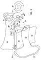
- FIG. 1A is a schematic diagram illustrating a human auditory system in which an access hole is created in the mastoid, to which a single component dual transducer support is affixed.
- FIG. 1B is a schematic diagram illustrating a further embodiment of the invention shown in FIG. 1A, in which ball and socket joints provide further adjustability of transducer position.
- FIG. 2 is a schematic diagram illustrating a human auditory system, showing an alternate embodiment of the dual transducer support shown in FIG. 1 A.
- FIG. 3 is a schematic diagram illustrating a human auditory system, showing an even further embodiment of the dual transducer support shown in FIG. 1 A.
- FIG. 4A is a schematic diagram illustrating yet another embodiment of a portion of the dual transducer support shown in FIGS. 1A, 2 , and 3 , the support having transducers affixed to opposite sides and having one mechanical fastener with adjustment slots/openings.
- FIG. 4B is a plan view of the dual transducer support shown in FIG. 4 A.
- FIG. 4C is a further embodiment of the invention shown in FIG. 4A, in which ball and socket joints provide further adjustability to transducer position.
- FIG. 5A is a schematic diagram illustrating yet another embodiment of a portion of the dual transducer support shown in FIGS. 1A, 2 , and 3 , the support having transducers attached to opposite sides and having two mechanical fasteners with adjustment slots/openings.
- FIG. 5B is a plan view of the dual transducer support shown in FIG. 5 A.
- FIG. 5C is a further embodiment of the invention shown in FIG. 5A, in which ball and socket joints provide further adjustability to transducer position.
- the invention provides a transducer support, which is particularly advantageous when used in a middle ear implantable hearing aid system, such as a partial middle ear implantable (P-MEI) or total middle ear implantable (T-MEI) hearing aid system.
- a P-MEI or T-MEI hearing aid system assists the human auditory system in converting acoustic energy contained within sound waves into electrochemical signals delivered to the brain and interpreted as sound.
- FIG. 1A illustrates generally the use of the invention in a human auditory system. Sound waves are directed into an external auditory canal 20 by an outer ear (pinna) 25 . The frequency characteristics of the sound waves are slightly modified by the resonant characteristics of the external auditory canal 20 .
- tympanic membrane eardrum
- tympanic cavity between it and the tympanic cavity (middle ear) 35 .
- Variations in the sound waves produce tympanic vibrations.
- the mechanical energy of the tympanic vibrations is communicated to the inner ear, comprising cochlea 60 , vestibule 61 , and semicircular canals 62 , by a sequence of articulating bones located in the middle ear 35 .
- This sequence of articulating bones is referred to generally as the ossicular chain.
- the tympanic membrane 30 and ossicular chain transform acoustic energy in the external auditory canal 20 to mechanical energy at the cochlea 60 .
- the ossicular chain includes three primary components: a malleus 40 , an incus (not shown), and a stapes 50 .
- the malleus 40 includes manubrium and head portions. The manubrium of the malleus 40 attaches to the tympanic membrane 30 . The head of the malleus 40 articulates with one end of the incus. The incus normally couples mechanical energy from the vibrating malleus 40 to the stapes 50 .
- the stapes 50 includes a capitulum portion, comprising a head and a neck, connected to a footplate portion by means of a support crus comprising two crura. The stapes 50 is disposed in and against a membrane-covered opening on the cochlea 60 .
- This membrane-covered opening between the cochlea 60 and middle ear 35 is referred to as the oval window 55 .
- Oval window 55 is considered part of cochlea 60 in this patent application. The incus articulates the capitulum of the stapes 50 to complete the mechanical transmission path.
- tympanic vibrations are mechanically conducted through the malleus 40 , incus, and stapes 50 , to the oval window 55 . Vibrations at the oval window 55 are conducted into the fluid-filled cochlea 60 . These mechanical vibrations generate fluidic motion, thereby transmitting hydraulic energy within the cochlea 60 . Pressures generated in the cochlea 60 by fluidic motion are accommodated by a second membrane-covered opening on the cochlea 60 . This second membrane-covered opening between the cochlea 60 and middle ear 35 is referred to as the round window 65 . Round window 65 is considered part of cochlea 60 in this patent application.
- Receptor cells in the cochlea 60 translate the fluidic motion into neural impulses which are transmitted to the brain and perceived as sound.
- various disorders of the tympanic membrane 30 , ossicular chain, and/or cochlea 60 can disrupt or impair normal hearing.
- Hearing loss due to damage in the cochlea is referred to as sensorineural hearing loss.
- Hearing loss due to an inability to conduct mechanical vibrations through the middle ear is referred to as conductive hearing loss.
- Some patients have an ossicular chain lacking sufficient resiliency to transmit mechanical vibrations between the tympanic membrane 30 and the oval window 55 .
- fluidic motion in the cochlea 60 is attenuated.
- receptor cells in the cochlea 60 do not receive adequate mechanical stimulation. Damaged elements of ossicular chain may also interrupt transmission of mechanical vibrations between the tympanic membrane 30 and the oval window 55 .
- tympanoplasty is used to surgically reconstruct the tympanic membrane 30 and establish ossicular continuity from the tympanic membrane 30 to the oval window 55 .
- Various passive mechanical prostheses and implantation techniques have been developed in connection with reconstructive surgery of the middle ear 35 for patients with damaged ossicles.
- Two basic forms of prosthesis are available: total ossicular replacement prostheses (TORP), which is connected between the tympanic membrane 30 and the oval window 55 ; and partial ossicular replacement prostheses (PORP), which is positioned between the tympanic membrane 30 and the stapes 50 .
- TORP total ossicular replacement prostheses
- PORP partial ossicular replacement prostheses
- a conventional “air conduction” hearing aid is sometimes used to overcome hearing loss due to sensorineural cochlear damage or mild conductive impediments to the ossicular chain.
- Conventional hearing aids utilize a microphone, which transduces sound into an electrical signal.
- Amplification circuitry amplifies the electrical signal.
- a speaker transduces the amplified electrical signal into acoustic energy transmitted to the tympanic membrane 30 .
- some of the transmitted acoustic energy is typically detected by the microphone, resulting in a feedback signal which degrades sound quality.
- Conventional hearing aids also often suffer from a significant amount of signal distortion.
- cochlear implant techniques implement an inner ear hearing aid system.
- Cochlear implants electrically stimulate auditory nerve fibers within the cochlea 60 .
- a typical cochlear implant system includes an external microphone, an external signal processor, and an external transmitter, as well as an implanted receiver and an implanted single channel or multichannel probe.
- a single channel probe has one electrode.
- a multichannel probe has an array of several electrodes.
- a signal processor converts speech signals transduced by the microphone into a series of sequential electrical pulses of different frequency bands within a speech frequency spectrum.
- Electrical pulses corresponding to low frequency sounds are delivered to electrodes that are more apical in the cochlea 60 .
- Electrical pulses corresponding to high frequency sounds are delivered to electrodes that are more basal in the cochlea 60 .
- the nerve fibers stimulated by the electrodes of the cochlear implant probe transmit neural impulses to the brain, where these neural impulses are interpreted as sound.
- temporal bone conduction hearing aid systems produce mechanical vibrations that are coupled to the cochlea 60 via a temporal bone in the skull.
- a vibrating element can be implemented percutaneously or subcutaneously.
- a particularly interesting class of hearing aid systems includes those which are configured for disposition principally within the middle ear 35 space.
- an electrical-to-mechanical output transducer couples mechanical vibrations to the ossicular chain, which is optionally interrupted to allow coupling of the mechanical vibrations to the ossicular chain.
- Both electromagnetic and piezoelectric output transducers have been used to effect the mechanical vibrations upon the ossicular chain.
- One example of a partial middle ear implantable (P-MEI) hearing aid system having an electromagnetic output transducer comprises: an external microphone transducing sound into electrical signals; external amplification and modulation circuitry; and an external radio frequency (RF) transmitter for transdermal RF communication of an electrical signal.
- An implanted receiver detects and rectifies the transmitted signal, driving an implanted coil in constant current mode.
- a resulting magnetic field from the implanted drive coil vibrates an implanted magnet that is permanently affixed only to the incus.
- Such electromagnetic output transducers have relatively high power consumption, which limits their usefulness in total middle ear implantable (T-MEI) hearing aid systems.
- a piezoelectric output transducer is also capable of effecting mechanical vibrations to the ossicular chain.
- An example of such a device is disclosed in U.S. Pat. No. 4,729,366, issued to D. W. Schaefer on Mar. 8, 1988.
- a mechanical-to-electrical piezoelectric input transducer is associated with the malleus 40 , transducing mechanical energy into-an electrical signal, which is amplified and further processed.
- a resulting electrical signal is provided to an electrical-to-mechanical piezoelectric output transducer that generates a mechanical vibration coupled to an element of the ossicular chain or to the oval window 55 or round window 65 .
- the ossicular chain is interrupted by removal of the incus. Removal of the incus prevents the mechanical vibrations delivered by the piezoelectric output transducer from mechanically feeding back to the piezoelectric input transducer.
- Piezoelectric output transducers have several advantages over electromagnetic output transducers.
- the smaller size or volume of the piezoelectric output transducer advantageously eases implantation into the middle ear 35 .
- the lower power consumption of the piezoelectric output transducer is particularly attractive for T-MEI hearing aid systems, which include a limited longevity implanted battery as a power source.
- This invention provides a support 110 for disposing transducers within the middle ear 35 for use in an implantable hearing aid (IHA).
- the invention is applicable for use with both P-MEI and T-MEI hearing aid systems.
- the support 110 is capable of carrying both input 115 and output transducers 120 on respective mounting portions.
- input 115 and output transducers 120 need not be separately introduced into the middle ear 35 .
- the electronics unit 100 of the IHA is separately implanted. This further eases implantation and repair or adjustment to the electronics unit 100 of the IHA. Maintenance and repairs, such as changing a battery in the electronics unit 100 of the IHA, are easily made without removing the support 110 .
- an access hole 85 is created in a region of the temporal bone known as the mastoid 80 .
- An incision is made in the skin covering the mastoid 80 , and an underlying access hole 85 is created through the mastoid 80 allowing external access to the middle ear 35 .
- the access hole 85 is located approximately posterior and superior to the external auditory canal 20 .
- a single component support 110 is implanted into the middle ear cavity 35 .
- Input and output transducers 115 and 120 are each affixed to the support 110 prior to implantation.
- One embodiment of the support 110 is illustrated generally in FIG. 1A, comprising one component. However, it is to be understood that the component can be fabricated in multiple parts and coupled together, mechanically or otherwise, to produce a single component support 110 .
- the shape of the support 110 is not critical, provided that the support 110 allows both transducers to be mounted on it, preferably one transducer on each end. However, other configurations are possible, depending on patient anatomy and other factors.
- the support can be a U-shaped component, as shown in FIG.
- support 110 is that the spacing between an input transducer 115 and an output transducer 120 disposed on the support 110 is approximately 10 to 20 millimeters, varying depending on the anatomical requirements of the patient.
- At least one input transducer 115 is affixed to a first mounting portion on a proximal end of the support 110 .
- the input transducer 115 mechanically engages at least one auditory element, such as the malleus 40 , preferably on the body of the malleus 40 at a force of approximately 10 dynes.
- At least one output transducer 120 is also affixed to a second mounting portion on a distal end of the support 110 .
- the output transducer 120 is coupled to at least one auditory element, such as the stapes 50 , preferably on the head of the stapes 50 at a force of approximately 10 dynes.
- the transducers 115 and 120 comprise any type of transducer well known to one skilled in the art.
- transducers 115 and 120 are ceramic piezoelectric bi-element transducers.
- Input transducer 115 transduces mechanical energy from vibration of an auditory element, such as the malleus 40 , into an electrical signal to the electronics unit 100 , which is preferably implanted in the mastoid 80 .
- the electronics unit 100 provides an amplified version of the electrical signal to the output transducer 120 .
- the output transducer 120 produces a resulting mechanical vibration, which is coupled to an auditory element such as the stapes 50 .
- the electronics unit 100 is electrically connected to input transducer 115 and output transducer 120 by any convenient technique, indicated schematically as leads 101 and 102 , respectively.
- the support 110 is also capable of receiving at least one bone screw 130 .
- the bone screw 130 secures the support 110 to the mastoid 80 .
- the bone screw 130 comprises any biocompatible material, and preferably is self-tapping; if so, it is captured by the support 110 and/or an opening created by the bone screw in the mastoid 80 , as well known to one skilled in the art.
- the support 110 also comprises any biocompatible material. Examples of biocompatible materials include titanium, stainless steel, certain ceramics (ex. alumina), certain polymers (ex. polycarbonates), and other materials well known to one skilled in the art.
- the bone screw 130 can be any type of screw well known to one skilled in the art, such as an orthopedic bone screw, a torx head screw, a single or double slotted head screw.
- the support 110 is preferably adapted to receive and hold the bone screw 130 such that the combination can be placed against the mastoid 80 as a single unit. Any suitable known technique, such as pre-threading or otherwise shaping the support 110 in accordance with known practices, is suitable.
- the incus is removed to prevent feedback of mechanical vibrations from the output transducer 120 to the input transducer 115 through the incus.
- a bone screw 130 or other fastener such as a biocompatible adhesive, mechanical vibrations of the output transducer 120 are not transmitted back to the input transducer 115 through the support 110 .
- universal connectors 190 are placed between mounting portions for each transducer 115 , 120 and the main support 110 .
- the universal connectors 190 such as ball and socket joints, allow further adjustability and 360 degree movement to position the transducers 115 and 120 against respective auditory elements 40 and 50 .
- the support 110 further comprises an arm 135 , extending from the support 110 towards the outer ear 35 through the access hole 85 .
- a bone screw 145 secures the arm 135 to the mastoid 80 and provides added stability to the support 110 .
- the arm 135 comprises any biocompatible material and is approximately one inch in length, extending approximately to the entrance of the access hole 85 created behind the outer ear 25 .
- the bone screw 145 used to affix the arm 135 to the mastoid 80 is of a similar type as the bone screw 130 used to affix the support 110 to the mastoid 80 .
- the arm 135 also allows for easy insertion of the support 110 into the access hole 85 and the middle ear 35 .
- the support 110 further comprises a lip 150 , extending outside the entrance of the access hole 85 from the arm 135 , where it is mounted subcutaneously to the mastoid bone 80 with a bone screw 160 .
- the lip 150 extends outward radially from the proximal end of arm 135 .
- the bone screw 160 used to attach the arm 135 to the mastoid bone 80 is of a similar type as the bone screw 130 used to attach the support 110 to the mastoid bone 80 .
- This embodiment increases support 110 stability and eases implantation, due to the addition of the arm 135 and lip 150 .
- the arm 135 can be integrally-fabricated with the lip 150 , so that they are one piece as in other embodiments.
- the single component support 110 shown in FIGS. 1 to 3 , is replaced with an adjustable support 100 , having two components 170 and 165 , as shown in FIGS. 4A and 4B.
- the support 110 allows for independent adjustments of the distance between the input and output transducers 115 and 120 , respectively, and the angle between the transducers 115 and 120 with respect to the support mounting screw 130 .
- Such independent adjustments allow multiple auditory elements, such as the malleus 40 and the stapes 50 , to be properly coupled to the input and output transducers 115 and 120 , respectively, in a patient population having varying anatomical features within the middle ear 35 .
- components 165 and 170 in this embodiment is not critical, provided that the support 110 allows both transducers to be mounted on it, preferably one transducer on each end. However, other configurations are possible, depending on patient anatomy and other factors.
- Components 165 and 170 can be L-shaped, as shown in FIG. 4A, rectangular-shaped, or any other shape that facilitates mounting of transducers 115 and 120 .
- Each support component 165 or 170 can be fabricated as multiple parts coupled together, mechanically or otherwise, to produce a single component 165 or 170 .
- a mechanical fastener such as a bone screw 130 , couples the support components 165 and 170 together and affixes the support 110 to the mastoid bone 80 .
- a bone screw 130 couples the support components 165 and 170 together and affixes the support 110 to the mastoid bone 80 .
- one of the two components 165 , 170 can be shaped with a flanged arm extending from it, such that the arm extends through the adjustment opening on the opposite component, coupling it with the flange.
- Each support component 165 and 170 has an opening 175 and 180 . At least one of the openings 175 , 180 comprises a slot.
- the bone screw 130 extends through mutually-aligned openings 175 and 180 on alternate support components 165 and 170 within the middle ear region 35 .
- Adjustment slots 175 and 180 operate by slidable, longitudinal positioning of support components 165 and 170 with respect to each other.
- the adjustment slots 175 and 180 also operate by radial positioning of each support component 165 , 170 with respect to the bone screw 130 .
- the resulting IHA support and transducers have positional stability and are invisible externally.
- Other types of adjustment techniques can be used in place of adjustment slots 175 and 180 .
- universal connectors 190 are placed between mounting portions for each transducer 115 , 120 and the respective main support component 165 , 170 .
- the universal connectors 190 such as ball and socket joints, allow further adjustability and 360 degree movement to position the transducers 115 and 120 against respective auditory elements 40 and 50 .
- the position of the transducers 115 and 120 is adjusted by manipulating two adjustment slots 175 and 180 within the middle ear region 35 , as shown in FIGS. 5A and 5B.
- the support also comprises two components 165 and 170 .
- each support component 165 or 170 can be fabricated in multiple parts and coupled together, mechanically or otherwise, to produce a single component 165 or 170 .
- Each support component 165 and 170 has at least one adjustment slot 175 and 180 , respectively.
- Two mechanical fasteners 130 and 185 extend through both support components 165 and 170 and respective mutually-aligned adjustment slots 175 and 180 on alternate support components 165 , 170 within the middle ear region 35 .
- the distance between the transducers 115 and 120 is adjusted by positioning of the adjustment slots 175 and 180 .
- the resulting IHA support and transducers also have positional stability and are invisible externally.
- the shape of the two support components 165 and 170 in this embodiment is not critical, provided that the support 110 allows both transducers 115 and 120 to be mounted on it, preferably one transducer 115 , 120 on each end. However, other configurations are possible, depending on patient anatomy and other factors.
- Each component 165 , 170 can be L-shaped, modified L-shaped, as shown in FIG. 5A, rectangular-shaped, or any other shape that facilitates mounting of transducers 115 and 120 to the support 110 .
- a bone screw 130 couples the two components 165 and 170 together and affixes the support 110 to the mastoid bone 80 , through an adjustment slot 180 on one component 170 .
- Another screw 185 couples the support components 165 and 170 together through a second adjustment slot 175 .
- This screw 185 comprises a similar material as the bone screw 130 that affixes the support 110 to the mastoid 80 , and it can also attach to the mastoid bone 80 for added stability.
- the distance between the transducers 115 and 120 is adjusted by positioning of the adjustment slots 175 and 180 .
- the adjustment slots 175 and 180 operate by allowing slidable, longitudinal positioning of the two components 165 and 170 with respect to each other.
- the distance between the transducers 115 and 120 is adjustable by approximately 5 millimeters in either direction.
- the resulting IHA support and transducers have positional stability and are invisible externally.
- other types of adjustment techniques can be used in place of adjustment slots 175 and 180 .
- universal connectors 190 are placed between mounting portions for each transducer 115 , 120 and the respective main support component 165 , 170 .
- the universal connectors 190 such as ball and socket joints, allow further adjustability and 360 degree movement to position the transducers 115 and 120 against respective auditory elements 40 and 50 .
Abstract
Description
Claims (22)
Priority Applications (1)
| Application Number | Priority Date | Filing Date | Title |
|---|---|---|---|
| US09/551,480 US6488616B1 (en) | 1996-08-07 | 2000-04-18 | Hearing aid transducer support |
Applications Claiming Priority (3)
| Application Number | Priority Date | Filing Date | Title |
|---|---|---|---|
| US08/695,099 US5836863A (en) | 1996-08-07 | 1996-08-07 | Hearing aid transducer support |
| US09/188,769 US6050933A (en) | 1996-08-07 | 1998-11-09 | Hearing aid transducer support |
| US09/551,480 US6488616B1 (en) | 1996-08-07 | 2000-04-18 | Hearing aid transducer support |
Related Parent Applications (1)
| Application Number | Title | Priority Date | Filing Date |
|---|---|---|---|
| US09/188,769 Division US6050933A (en) | 1996-08-07 | 1998-11-09 | Hearing aid transducer support |
Publications (1)
| Publication Number | Publication Date |
|---|---|
| US6488616B1 true US6488616B1 (en) | 2002-12-03 |
Family
ID=24791554
Family Applications (3)
| Application Number | Title | Priority Date | Filing Date |
|---|---|---|---|
| US08/695,099 Expired - Fee Related US5836863A (en) | 1996-08-07 | 1996-08-07 | Hearing aid transducer support |
| US09/188,769 Expired - Fee Related US6050933A (en) | 1996-08-07 | 1998-11-09 | Hearing aid transducer support |
| US09/551,480 Expired - Fee Related US6488616B1 (en) | 1996-08-07 | 2000-04-18 | Hearing aid transducer support |
Family Applications Before (2)
| Application Number | Title | Priority Date | Filing Date |
|---|---|---|---|
| US08/695,099 Expired - Fee Related US5836863A (en) | 1996-08-07 | 1996-08-07 | Hearing aid transducer support |
| US09/188,769 Expired - Fee Related US6050933A (en) | 1996-08-07 | 1998-11-09 | Hearing aid transducer support |
Country Status (3)
| Country | Link |
|---|---|
| US (3) | US5836863A (en) |
| EP (1) | EP0920786A1 (en) |
| WO (1) | WO1998006237A1 (en) |
Cited By (6)
| Publication number | Priority date | Publication date | Assignee | Title |
|---|---|---|---|---|
| US20040088797A1 (en) * | 1998-11-17 | 2004-05-13 | Fisher & Paykel Limited | Laundry machine |
| US20040158940A1 (en) * | 2000-04-17 | 2004-08-19 | The Procter & Gamble Company | Phase-separated rinse-off hair coloring/cleansing products |
| US20080004486A1 (en) * | 2006-06-14 | 2008-01-03 | Otologics, Llc | Compressive coupling of an implantable hearing aid actuator to an auditory component |
| US7722525B2 (en) | 2007-05-24 | 2010-05-25 | Otologics, Llc | Lateral coupling of an implantable hearing aid actuator to an auditory component |
| WO2010133704A3 (en) * | 2010-09-27 | 2011-06-30 | Advanced Bionics Ag | Implantable hearing instrument |
| WO2020222110A1 (en) * | 2019-05-02 | 2020-11-05 | Cochlear Limited | Osseointegrating ring for coupling of bone conduction device |
Families Citing this family (64)
| Publication number | Priority date | Publication date | Assignee | Title |
|---|---|---|---|---|
| US5836863A (en) * | 1996-08-07 | 1998-11-17 | St. Croix Medical, Inc. | Hearing aid transducer support |
| US6315710B1 (en) * | 1997-07-21 | 2001-11-13 | St. Croix Medical, Inc. | Hearing system with middle ear transducer mount |
| US6325755B1 (en) * | 1997-08-07 | 2001-12-04 | St. Croix Medical, Inc. | Mountable transducer assembly with removable sleeve |
| WO1999063785A2 (en) | 1998-06-05 | 1999-12-09 | St. Croix Medical, Inc. | Reduced feedback in implantable hearing assistance systems |
| US6077215A (en) * | 1998-10-08 | 2000-06-20 | Implex Gmbh Spezialhorgerate | Method for coupling an electromechanical transducer of an implantable hearing aid or tinnitus masker to a middle ear ossicle |
| US6261223B1 (en) * | 1998-10-15 | 2001-07-17 | St. Croix Medical, Inc. | Method and apparatus for fixation type feedback reduction in implantable hearing assistance system |
| DE10084133T1 (en) * | 1999-02-05 | 2002-01-31 | St Croix Medical Inc | Method and device for a programmable implantable hearing aid |
| DE19914993C1 (en) | 1999-04-01 | 2000-07-20 | Implex Hear Tech Ag | Fully implantable hearing system with telemetric sensor testing has measurement and wireless telemetry units on implant side for transmitting processed signal to external display/evaluation unit |
| DE19915846C1 (en) | 1999-04-08 | 2000-08-31 | Implex Hear Tech Ag | Partially implantable system for rehabilitating hearing trouble includes a cordless telemetry device to transfer data between an implantable part, an external unit and an energy supply. |
| DE19923403C2 (en) | 1999-05-21 | 2002-11-14 | Phonak Ag Staefa | Device for mechanically coupling an electromechanical hearing aid transducer that can be implanted in a mastoid cavity |
| DE19931788C1 (en) | 1999-07-08 | 2000-11-30 | Implex Hear Tech Ag | Implanted mechanical coupling device for auditory ossicle chain in hearing aid system has associated settling device for movement of coupling device between open and closed positions |
| DE19935029C2 (en) | 1999-07-26 | 2003-02-13 | Phonak Ag Staefa | Implantable arrangement for mechanically coupling a driver part to a coupling point |
| DE19948336C2 (en) | 1999-10-07 | 2002-02-28 | Implex Hear Tech Ag | Arrangement for coupling a driver to a coupling point of the ossicle chain |
| DE19948375B4 (en) | 1999-10-07 | 2004-04-01 | Phonak Ag | Arrangement for mechanically coupling a driver to a coupling point of the ossicle chain |
| US6554761B1 (en) | 1999-10-29 | 2003-04-29 | Soundport Corporation | Flextensional microphones for implantable hearing devices |
| US6629922B1 (en) | 1999-10-29 | 2003-10-07 | Soundport Corporation | Flextensional output actuators for surgically implantable hearing aids |
| DE10015421C2 (en) | 2000-03-28 | 2002-07-04 | Implex Ag Hearing Technology I | Partially or fully implantable hearing system |
| US6293903B1 (en) | 2000-05-30 | 2001-09-25 | Otologics Llc | Apparatus and method for mounting implantable hearing aid device |
| DE10039401C2 (en) | 2000-08-11 | 2002-06-13 | Implex Ag Hearing Technology I | At least partially implantable hearing system |
| DE10041726C1 (en) | 2000-08-25 | 2002-05-23 | Implex Ag Hearing Technology I | Implantable hearing system with means for measuring the coupling quality |
| DE10047388C1 (en) | 2000-09-25 | 2002-01-10 | Implex Hear Tech Ag | Implantable hearing system, includes a detachable coupling for securing and locating a transducer and a micro-manipulator |
| US7090673B2 (en) * | 2001-04-06 | 2006-08-15 | Sherwood Services Ag | Vessel sealer and divider |
| US6730015B2 (en) | 2001-06-01 | 2004-05-04 | Mike Schugt | Flexible transducer supports |
| WO2004043290A2 (en) * | 2002-11-08 | 2004-05-27 | Advanced Bionics Corporation | Implanted outer ear canal hearing aid |
| DE20219862U1 (en) * | 2002-12-21 | 2003-02-27 | Heinz Kurz Gmbh Medizintechnik | Device for attaching a magnet or an electrical coil to the human middle ear |
| DE10301723B3 (en) * | 2003-01-15 | 2004-09-16 | Med-El Elektromedizinische Geräte GmbH | Implantable electromechanical transducer |
| US7668325B2 (en) | 2005-05-03 | 2010-02-23 | Earlens Corporation | Hearing system having an open chamber for housing components and reducing the occlusion effect |
| US8295523B2 (en) | 2007-10-04 | 2012-10-23 | SoundBeam LLC | Energy delivery and microphone placement methods for improved comfort in an open canal hearing aid |
| US7867160B2 (en) | 2004-10-12 | 2011-01-11 | Earlens Corporation | Systems and methods for photo-mechanical hearing transduction |
| EP1792519A4 (en) * | 2004-09-10 | 2010-09-15 | Otologics Llc | Adjustable bone bracket |
| US8142344B2 (en) * | 2005-02-25 | 2012-03-27 | Advanced Bionics Ag | Fully implantable hearing aid system |
| CN101437539B (en) | 2005-07-05 | 2013-10-02 | 康奈尔研究基金会(有限公司) | Blocking leukocyte emigration and inflammation by interfering with CD99l2 |
| US8469908B2 (en) * | 2007-04-06 | 2013-06-25 | Wilson T. Asfora | Analgesic implant device and system |
| US8512264B1 (en) | 2007-04-06 | 2013-08-20 | Wilson T. Asfora | Analgesic implant device and system |
| WO2009049320A1 (en) | 2007-10-12 | 2009-04-16 | Earlens Corporation | Multifunction system and method for integrated hearing and communiction with noise cancellation and feedback management |
| WO2009062172A2 (en) * | 2007-11-08 | 2009-05-14 | Otologics, Llc | Spanning connector for implantable hearing instrument |
| DK2301262T3 (en) | 2008-06-17 | 2017-11-13 | Earlens Corp | Optical electromechanical hearing aids with combined power and signal structure |
| BRPI0915203A2 (en) | 2008-06-17 | 2016-02-16 | Earlens Corp | device, system and method for transmitting an audio signal, and device and method for stimulating a target tissue |
| US8396239B2 (en) | 2008-06-17 | 2013-03-12 | Earlens Corporation | Optical electro-mechanical hearing devices with combined power and signal architectures |
| AU2009282740A1 (en) * | 2008-08-21 | 2010-02-25 | Med-El Elektromedizinische Geraete Gmbh | Multipath stimulation hearing systems |
| KR20110086804A (en) | 2008-09-22 | 2011-08-01 | 사운드빔, 엘엘씨 | Balanced armature devices and methods for hearing |
| CN102598712A (en) | 2009-06-05 | 2012-07-18 | 音束有限责任公司 | Optically coupled acoustic middle ear implant systems and methods |
| US9544700B2 (en) | 2009-06-15 | 2017-01-10 | Earlens Corporation | Optically coupled active ossicular replacement prosthesis |
| CN102598713A (en) | 2009-06-18 | 2012-07-18 | 音束有限责任公司 | Eardrum implantable devices for hearing systems and methods |
| EP2443773B1 (en) | 2009-06-18 | 2017-01-11 | Earlens Corporation | Optically coupled cochlear implant systems |
| BRPI1016075A2 (en) | 2009-06-22 | 2016-05-10 | SoundBeam LLC | device for transmitting sound to a user's ear and associated methods. |
| EP2446645B1 (en) | 2009-06-22 | 2020-05-06 | Earlens Corporation | Optically coupled bone conduction systems and methods |
| WO2010151647A2 (en) | 2009-06-24 | 2010-12-29 | SoundBeam LLC | Optically coupled cochlear actuator systems and methods |
| WO2010151636A2 (en) | 2009-06-24 | 2010-12-29 | SoundBeam LLC | Optical cochlear stimulation devices and methods |
| EP2656639B1 (en) | 2010-12-20 | 2020-05-13 | Earlens Corporation | Anatomically customized ear canal hearing apparatus |
| KR101223700B1 (en) | 2011-07-01 | 2013-01-21 | 경북대학교 산학협력단 | Supporting module for round window driving transducer with excellent supporting durability |
| US20170208403A1 (en) * | 2013-11-25 | 2017-07-20 | Massachusettes Eye And Ear Infirmary | Piezoelectric sensors for hearing aids |
| US10034103B2 (en) | 2014-03-18 | 2018-07-24 | Earlens Corporation | High fidelity and reduced feedback contact hearing apparatus and methods |
| EP3169396B1 (en) | 2014-07-14 | 2021-04-21 | Earlens Corporation | Sliding bias and peak limiting for optical hearing devices |
| US9924276B2 (en) | 2014-11-26 | 2018-03-20 | Earlens Corporation | Adjustable venting for hearing instruments |
| DK3355801T3 (en) | 2015-10-02 | 2021-06-21 | Earlens Corp | Adapted ear canal device for drug delivery |
| US10321247B2 (en) | 2015-11-27 | 2019-06-11 | Cochlear Limited | External component with inductance and mechanical vibratory functionality |
| US10492010B2 (en) | 2015-12-30 | 2019-11-26 | Earlens Corporations | Damping in contact hearing systems |
| US11350226B2 (en) | 2015-12-30 | 2022-05-31 | Earlens Corporation | Charging protocol for rechargeable hearing systems |
| US10178483B2 (en) | 2015-12-30 | 2019-01-08 | Earlens Corporation | Light based hearing systems, apparatus, and methods |
| CN109952771A (en) | 2016-09-09 | 2019-06-28 | 伊尔兰斯公司 | Contact hearing system, device and method |
| WO2018093733A1 (en) | 2016-11-15 | 2018-05-24 | Earlens Corporation | Improved impression procedure |
| WO2019173470A1 (en) | 2018-03-07 | 2019-09-12 | Earlens Corporation | Contact hearing device and retention structure materials |
| WO2019199680A1 (en) | 2018-04-09 | 2019-10-17 | Earlens Corporation | Dynamic filter |
Citations (54)
| Publication number | Priority date | Publication date | Assignee | Title |
|---|---|---|---|---|
| US3557775A (en) | 1963-12-27 | 1971-01-26 | Jack Lawrence Mahoney | Method of implanting a hearing aid |
| US3594514A (en) | 1970-01-02 | 1971-07-20 | Medtronic Inc | Hearing aid with piezoelectric ceramic element |
| US3712962A (en) | 1971-04-05 | 1973-01-23 | J Epley | Implantable piezoelectric hearing aid |
| US3764748A (en) | 1972-05-19 | 1973-10-09 | J Branch | Implanted hearing aids |
| US3870832A (en) | 1972-07-18 | 1975-03-11 | John M Fredrickson | Implantable electromagnetic hearing aid |
| US3882285A (en) | 1973-10-09 | 1975-05-06 | Vicon Instr Company | Implantable hearing aid and method of improving hearing |
| US3931648A (en) | 1975-01-08 | 1976-01-13 | Richards Manufacturing Company | Stapedial prosthesis |
| US3992725A (en) | 1973-11-16 | 1976-11-23 | Homsy Charles A | Implantable material and appliances and method of stabilizing body implants |
| US4150262A (en) | 1974-11-18 | 1979-04-17 | Hiroshi Ono | Piezoelectric bone conductive in ear voice sounds transmitting and receiving apparatus |
| DE2834891A1 (en) | 1978-06-28 | 1980-01-03 | Synthes Ag | FIXATORS TO FIX BONES OR BONE FRUITS, ESPECIALLY VERBLE, TOGETHER |
| US4315433A (en) | 1980-03-19 | 1982-02-16 | The United States Of America As Represented By The Secretary Of The Army | Polymer film accelerometer |
| US4498461A (en) | 1981-12-01 | 1985-02-12 | Bo Hakansson | Coupling to a bone-anchored hearing aid |
| US4601723A (en) | 1985-01-29 | 1986-07-22 | Mcgrew Robert N | Telescoping self-adjusting ossicular prostheses |
| US4606329A (en) | 1985-05-22 | 1986-08-19 | Xomed, Inc. | Implantable electromagnetic middle-ear bone-conduction hearing aid device |
| US4628907A (en) | 1984-03-22 | 1986-12-16 | Epley John M | Direct contact hearing aid apparatus |
| EP0231162A1 (en) | 1986-01-27 | 1987-08-05 | Michel Gersdorff | Middle ear prosthesis |
| US4729366A (en) * | 1984-12-04 | 1988-03-08 | Medical Devices Group, Inc. | Implantable hearing aid and method of improving hearing |
| US4756312A (en) | 1984-03-22 | 1988-07-12 | Advanced Hearing Technology, Inc. | Magnetic attachment device for insertion and removal of hearing aid |
| US4774933A (en) | 1987-05-18 | 1988-10-04 | Xomed, Inc. | Method and apparatus for implanting hearing device |
| US4776322A (en) | 1985-05-22 | 1988-10-11 | Xomed, Inc. | Implantable electromagnetic middle-ear bone-conduction hearing aid device |
| US4817607A (en) | 1986-03-07 | 1989-04-04 | Richards Medical Company | Magnetic ossicular replacement prosthesis |
| US4840178A (en) | 1986-03-07 | 1989-06-20 | Richards Metal Company | Magnet for installation in the middle ear |
| US4850962A (en) | 1984-12-04 | 1989-07-25 | Medical Devices Group, Inc. | Implantable hearing aid and method of improving hearing |
| US4957507A (en) | 1987-12-14 | 1990-09-18 | Edmundas Lenkauskas | Wire spring prosthesis for ossicular reconstruction |
| US4957478A (en) * | 1988-10-17 | 1990-09-18 | Maniglia Anthony J | Partially implantable hearing aid device |
| US4969900A (en) | 1987-03-06 | 1990-11-13 | Gerald Fleischer | Middle ear prosthesis and method for mounting it |
| DE3918329A1 (en) | 1989-06-05 | 1990-12-06 | Hortmann Gmbh | Hearing aid with electrical stimulation of inner ear - has microphone coupled to implanted system with inductive coupling element |
| US4988333A (en) | 1988-09-09 | 1991-01-29 | Storz Instrument Company | Implantable middle ear hearing aid system and acoustic coupler therefor |
| US5012520A (en) | 1988-05-06 | 1991-04-30 | Siemens Aktiengesellschaft | Hearing aid with wireless remote control |
| US5015224A (en) | 1988-10-17 | 1991-05-14 | Maniglia Anthony J | Partially implantable hearing aid device |
| US5015225A (en) | 1985-05-22 | 1991-05-14 | Xomed, Inc. | Implantable electromagnetic middle-ear bone-conduction hearing aid device |
| WO1992008330A1 (en) | 1990-11-01 | 1992-05-14 | Cochlear Pty. Limited | Bimodal speech processor |
| US5163957A (en) | 1991-09-10 | 1992-11-17 | Smith & Nephew Richards, Inc. | Ossicular prosthesis for mounting magnet |
| US5277694A (en) | 1991-02-13 | 1994-01-11 | Implex Gmbh | Electromechanical transducer for implantable hearing aids |
| US5282858A (en) | 1991-06-17 | 1994-02-01 | American Cyanamid Company | Hermetically sealed implantable transducer |
| WO1994017645A1 (en) | 1993-01-25 | 1994-08-04 | Auditory Micromachines, Inc. | Implantable auditory system with micromachined microsensor and microactuator |
| US5338287A (en) | 1991-12-23 | 1994-08-16 | Miller Gale W | Electromagnetic induction hearing aid device |
| US5344422A (en) | 1989-10-30 | 1994-09-06 | Synthes (U.S.A.) | Pedicular screw clamp |
| US5360388A (en) | 1992-10-09 | 1994-11-01 | The University Of Virginia Patents Foundation | Round window electromagnetic implantable hearing aid |
| US5370689A (en) | 1992-07-23 | 1994-12-06 | Xomed-Treace, Inc. | Method of implanting a middle ear prosthesis |
| US5411467A (en) | 1989-06-02 | 1995-05-02 | Implex Gmbh Spezialhorgerate | Implantable hearing aid |
| US5456654A (en) | 1993-07-01 | 1995-10-10 | Ball; Geoffrey R. | Implantable magnetic hearing aid transducer |
| US5498226A (en) | 1990-03-05 | 1996-03-12 | Lenkauskas; Edmundas | Totally implanted hearing device |
| US5554096A (en) | 1993-07-01 | 1996-09-10 | Symphonix | Implantable electromagnetic hearing transducer |
| US5558618A (en) | 1995-01-23 | 1996-09-24 | Maniglia; Anthony J. | Semi-implantable middle ear hearing device |
| US5624376A (en) | 1993-07-01 | 1997-04-29 | Symphonix Devices, Inc. | Implantable and external hearing systems having a floating mass transducer |
| DE19618961A1 (en) | 1996-05-10 | 1997-11-13 | Implex Gmbh | Device for electromechanical stimulation and hearing testing |
| WO1998006235A1 (en) | 1996-08-07 | 1998-02-12 | St. Croix Medical, Inc. | Implantable hearing system having multiple transducers |
| WO1998006237A1 (en) | 1996-08-07 | 1998-02-12 | St. Croix Medical, Inc. | Hearing aid transducer support |
| DE19638159A1 (en) | 1996-09-18 | 1998-04-02 | Implex Gmbh | Fully implantable hearing aid with electrical hearing stimulation |
| DE19638158A1 (en) | 1996-09-18 | 1998-04-02 | Implex Gmbh | Implantable microphone |
| US5788711A (en) | 1996-05-10 | 1998-08-04 | Implex Gmgh Spezialhorgerate | Implantable positioning and fixing system for actuator and sensor implants |
| US5993376A (en) | 1997-08-07 | 1999-11-30 | St. Croix Medical, Inc. | Electromagnetic input transducers for middle ear sensing |
| US6001129A (en) | 1996-08-07 | 1999-12-14 | St. Croix Medical, Inc. | Hearing aid transducer support |
Family Cites Families (1)
| Publication number | Priority date | Publication date | Assignee | Title |
|---|---|---|---|---|
| US5496226A (en) * | 1994-05-17 | 1996-03-05 | Dixon Industries, Inc. | Friction drive unit for riding lawn mowers and the like |
-
1996
- 1996-08-07 US US08/695,099 patent/US5836863A/en not_active Expired - Fee Related
-
1997
- 1997-08-07 WO PCT/US1997/013808 patent/WO1998006237A1/en not_active Application Discontinuation
- 1997-08-07 EP EP97935315A patent/EP0920786A1/en not_active Withdrawn
-
1998
- 1998-11-09 US US09/188,769 patent/US6050933A/en not_active Expired - Fee Related
-
2000
- 2000-04-18 US US09/551,480 patent/US6488616B1/en not_active Expired - Fee Related
Patent Citations (58)
| Publication number | Priority date | Publication date | Assignee | Title |
|---|---|---|---|---|
| US3557775A (en) | 1963-12-27 | 1971-01-26 | Jack Lawrence Mahoney | Method of implanting a hearing aid |
| US3594514A (en) | 1970-01-02 | 1971-07-20 | Medtronic Inc | Hearing aid with piezoelectric ceramic element |
| US3712962A (en) | 1971-04-05 | 1973-01-23 | J Epley | Implantable piezoelectric hearing aid |
| US3764748A (en) | 1972-05-19 | 1973-10-09 | J Branch | Implanted hearing aids |
| US3870832A (en) | 1972-07-18 | 1975-03-11 | John M Fredrickson | Implantable electromagnetic hearing aid |
| US3882285A (en) | 1973-10-09 | 1975-05-06 | Vicon Instr Company | Implantable hearing aid and method of improving hearing |
| US3992725A (en) | 1973-11-16 | 1976-11-23 | Homsy Charles A | Implantable material and appliances and method of stabilizing body implants |
| US4150262A (en) | 1974-11-18 | 1979-04-17 | Hiroshi Ono | Piezoelectric bone conductive in ear voice sounds transmitting and receiving apparatus |
| US3931648A (en) | 1975-01-08 | 1976-01-13 | Richards Manufacturing Company | Stapedial prosthesis |
| DE2834891A1 (en) | 1978-06-28 | 1980-01-03 | Synthes Ag | FIXATORS TO FIX BONES OR BONE FRUITS, ESPECIALLY VERBLE, TOGETHER |
| US4315433A (en) | 1980-03-19 | 1982-02-16 | The United States Of America As Represented By The Secretary Of The Army | Polymer film accelerometer |
| US4498461A (en) | 1981-12-01 | 1985-02-12 | Bo Hakansson | Coupling to a bone-anchored hearing aid |
| US4628907A (en) | 1984-03-22 | 1986-12-16 | Epley John M | Direct contact hearing aid apparatus |
| US4756312A (en) | 1984-03-22 | 1988-07-12 | Advanced Hearing Technology, Inc. | Magnetic attachment device for insertion and removal of hearing aid |
| US4729366A (en) * | 1984-12-04 | 1988-03-08 | Medical Devices Group, Inc. | Implantable hearing aid and method of improving hearing |
| US4850962A (en) | 1984-12-04 | 1989-07-25 | Medical Devices Group, Inc. | Implantable hearing aid and method of improving hearing |
| US4601723A (en) | 1985-01-29 | 1986-07-22 | Mcgrew Robert N | Telescoping self-adjusting ossicular prostheses |
| US4776322A (en) | 1985-05-22 | 1988-10-11 | Xomed, Inc. | Implantable electromagnetic middle-ear bone-conduction hearing aid device |
| US4606329A (en) | 1985-05-22 | 1986-08-19 | Xomed, Inc. | Implantable electromagnetic middle-ear bone-conduction hearing aid device |
| US5015225A (en) | 1985-05-22 | 1991-05-14 | Xomed, Inc. | Implantable electromagnetic middle-ear bone-conduction hearing aid device |
| US4728327A (en) | 1986-01-27 | 1988-03-01 | Michel Gersdorff | Middle-ear prosthesis |
| EP0231162A1 (en) | 1986-01-27 | 1987-08-05 | Michel Gersdorff | Middle ear prosthesis |
| US4817607A (en) | 1986-03-07 | 1989-04-04 | Richards Medical Company | Magnetic ossicular replacement prosthesis |
| US4840178A (en) | 1986-03-07 | 1989-06-20 | Richards Metal Company | Magnet for installation in the middle ear |
| EP0263254A1 (en) | 1986-08-11 | 1988-04-13 | Medical Devices Group, Inc. | Implantable hearing aid |
| US4969900A (en) | 1987-03-06 | 1990-11-13 | Gerald Fleischer | Middle ear prosthesis and method for mounting it |
| US4774933A (en) | 1987-05-18 | 1988-10-04 | Xomed, Inc. | Method and apparatus for implanting hearing device |
| US4957507A (en) | 1987-12-14 | 1990-09-18 | Edmundas Lenkauskas | Wire spring prosthesis for ossicular reconstruction |
| US5012520A (en) | 1988-05-06 | 1991-04-30 | Siemens Aktiengesellschaft | Hearing aid with wireless remote control |
| US4988333A (en) | 1988-09-09 | 1991-01-29 | Storz Instrument Company | Implantable middle ear hearing aid system and acoustic coupler therefor |
| US5015224A (en) | 1988-10-17 | 1991-05-14 | Maniglia Anthony J | Partially implantable hearing aid device |
| US4957478A (en) * | 1988-10-17 | 1990-09-18 | Maniglia Anthony J | Partially implantable hearing aid device |
| US5411467A (en) | 1989-06-02 | 1995-05-02 | Implex Gmbh Spezialhorgerate | Implantable hearing aid |
| DE3918329A1 (en) | 1989-06-05 | 1990-12-06 | Hortmann Gmbh | Hearing aid with electrical stimulation of inner ear - has microphone coupled to implanted system with inductive coupling element |
| US5344422A (en) | 1989-10-30 | 1994-09-06 | Synthes (U.S.A.) | Pedicular screw clamp |
| US5498226A (en) | 1990-03-05 | 1996-03-12 | Lenkauskas; Edmundas | Totally implanted hearing device |
| WO1992008330A1 (en) | 1990-11-01 | 1992-05-14 | Cochlear Pty. Limited | Bimodal speech processor |
| US5277694A (en) | 1991-02-13 | 1994-01-11 | Implex Gmbh | Electromechanical transducer for implantable hearing aids |
| US5282858A (en) | 1991-06-17 | 1994-02-01 | American Cyanamid Company | Hermetically sealed implantable transducer |
| US5163957A (en) | 1991-09-10 | 1992-11-17 | Smith & Nephew Richards, Inc. | Ossicular prosthesis for mounting magnet |
| US5338287A (en) | 1991-12-23 | 1994-08-16 | Miller Gale W | Electromagnetic induction hearing aid device |
| US5370689A (en) | 1992-07-23 | 1994-12-06 | Xomed-Treace, Inc. | Method of implanting a middle ear prosthesis |
| US5360388A (en) | 1992-10-09 | 1994-11-01 | The University Of Virginia Patents Foundation | Round window electromagnetic implantable hearing aid |
| WO1994017645A1 (en) | 1993-01-25 | 1994-08-04 | Auditory Micromachines, Inc. | Implantable auditory system with micromachined microsensor and microactuator |
| US5531787A (en) | 1993-01-25 | 1996-07-02 | Lesinski; S. George | Implantable auditory system with micromachined microsensor and microactuator |
| US5554096A (en) | 1993-07-01 | 1996-09-10 | Symphonix | Implantable electromagnetic hearing transducer |
| US5624376A (en) | 1993-07-01 | 1997-04-29 | Symphonix Devices, Inc. | Implantable and external hearing systems having a floating mass transducer |
| US5456654A (en) | 1993-07-01 | 1995-10-10 | Ball; Geoffrey R. | Implantable magnetic hearing aid transducer |
| US5558618A (en) | 1995-01-23 | 1996-09-24 | Maniglia; Anthony J. | Semi-implantable middle ear hearing device |
| US5788711A (en) | 1996-05-10 | 1998-08-04 | Implex Gmgh Spezialhorgerate | Implantable positioning and fixing system for actuator and sensor implants |
| DE19618961A1 (en) | 1996-05-10 | 1997-11-13 | Implex Gmbh | Device for electromechanical stimulation and hearing testing |
| WO1998006235A1 (en) | 1996-08-07 | 1998-02-12 | St. Croix Medical, Inc. | Implantable hearing system having multiple transducers |
| WO1998006237A1 (en) | 1996-08-07 | 1998-02-12 | St. Croix Medical, Inc. | Hearing aid transducer support |
| US5836863A (en) * | 1996-08-07 | 1998-11-17 | St. Croix Medical, Inc. | Hearing aid transducer support |
| US6001129A (en) | 1996-08-07 | 1999-12-14 | St. Croix Medical, Inc. | Hearing aid transducer support |
| DE19638159A1 (en) | 1996-09-18 | 1998-04-02 | Implex Gmbh | Fully implantable hearing aid with electrical hearing stimulation |
| DE19638158A1 (en) | 1996-09-18 | 1998-04-02 | Implex Gmbh | Implantable microphone |
| US5993376A (en) | 1997-08-07 | 1999-11-30 | St. Croix Medical, Inc. | Electromagnetic input transducers for middle ear sensing |
Non-Patent Citations (31)
| Title |
|---|
| A Wengen, M.D., D.F., et al., "Measurements of the Stapes Superstructure," Ann. Otol. Rhinol. Laryngology, 104:311-316, (1995). |
| Dormer, PhD., K.J., et al., "Selection of Biomaterials for Middle and Inner Ear Implants," Otolaryngologic Clinics Of North America, 28:17-27, (1995). |
| Dumon, M.D., T., et al., "Piezolelectric Middle Ear Implant Preserving the Ossicular Chain," Orolaryngologic Clinics of North America, 28:173-188, (1995). |
| Fredrickson, M.D., J.M., et al., "Ongoing Investigations into an Implantable Electromagnetic Hearing Aid for Moderate to Severe Sensorineural Hearing Loss," Otolaryngologic Clinics of North America, 28:107-120, (1995). |
| Goode, M.D., R.L., et al., "New Knowledge About the Function of the Human Middle Ear: Development of an Improved Analog Model," American Journal of Otology, 15:145-154, (1994). |
| Goode, M.D., R.L., et al., "The History and Development of the Implantable Hearing Aid," Otolaryngologic Clinics of North America, 28:1-16, (1995). |
| Gyo, K., et al., "Sound Pickup Utilizing an Implantable Piezoelectric Ceramic Bimorph Element: Application to the Cochlear, Implant," American Journal of Otology, 5:273-276, (1984). |
| Gyo, K., et al., "Stapes Vibration Produced by the Output Transducer of an Implantable Hearing Aid," Archives of Otolaryngology Head and Neck Surgery, 113:1078-1081, (1987). |
| Jako, M.D., G.J., "Biomedical Engineering in Ear Surgery," Otolaryngologic Clinics of North America, 5:173-182, (1972). |
| Ko, PhD., W., "Engineering Principles of Mechanical Stimulation of the Middle Ear,"Otolaryngologic Clinics of North America, 28:29-41, (1995). |
| Ko, PhD., W.H., "A Preliminary Study on the Implantable Middle Ear Hearing Aid," I.E.E.E. 9th Annual Conference on Engineering in Medicine and Biology Society, (1987). |
| Kodera, M.D., et al., "Sound Evaluation of Partially Implantalbe Piezoelectric Middle Ear Implant: Comparative Study of Frequency Responses," Ear, Nose and Throat Journal, 73:108-111, (1994). |
| Lenkauskas, E., "Totally Implantable Hearing Aid Device," Transplants and Implants in Otology II, 371-375, (1991). |
| Maniglia, M.D., A.J., "Implantable Hearing Devices: State of the Art," Otolaryngologic Clinics of North America, 28:175-200, (1989). |
| Maniglia, M.D., A.J., et al., "Contactless Semi-Implantable Electromagnetic Middle Ear Device for the Treatment of Sensorineural Hearing Loss: Short-Term and Long-Term Animal Experiments," Otolaryngologic Clinics of North America, 28:121-140, (1995). |
| Maniglia, M.D., A.J., et al., "Electromagnetic Implantable Middle Ear Hearing Device of the Ossicular-Stimulating Type: Principles, Designs, and Experiments," Ann. Orol. Rhinol Laryngol, 97 (Suppl 136), part 2, (1998). |
| Maniglia, M.D., A.J., et al., "Electromagnetic Implantable Middle Ear Hearing Device of the Ossicular-Stimulating Type: Principles, Designs, and Experiments," Ann. Otol. Rhinol Laryngol, 97 (Suppl 136), part 2, (1988). |
| Ohno, T., "The Implantable Hearing Aid," Audecibel, Fall 1984, Winter 1985, (1984). |
| Onchi, Y., "Mechanism of the Middle Ear," Journal of the Acoustical Society of America, 33:794-805, (1961). |
| Snik, PhD., Ad F.M., et al., "The Bone-Anchored Hearing Aid Compared with Conventional Hearing Aids: Audiologic Results and the Patients' Opinions," Otolaryngologic Clinics of North America, 28:73-84, (1995). |
| Suzuki, J.I., et al., "Implantation of Partially Implantable Middle Ear Implant and the Indication," Advances in Audiology (Karger, Basel), 4:160-166, (1988). |
| Suzuki, J.I., et al., "Principle, Construction and Indication of the Middle Ear Implant," Advances in Audiology, 4:15-21, (1988). |
| Suzuki, J.L., et al., "Long-Term Clinical Results of the Partially Implantable Piezoelectric Middle Ear Implant," Ear, Nose and Throat Journal, 73(2): 104-107, (Feb. 1994). |
| Suzuki, M.D., J.L., et al., "Partially Implantable Piezoelectric Middle Ear Hearing Device: Long-Term Results," Otolaryngologic Clinics of North America, 28:99-106, (1995). |
| Tjellstrom, M.D., PhD., A., "The Bone-Anchored Hearing Aid," Otolaryngolgic Clinics of North America, 28:53-72, (1995. |
| Tos, M., et al., "Implantation of Electromagnetic Ossicular Replacement Device," Ear, Nose and Throat Journal, 73(2):93-103, (Feb. 1994). |
| Welling, D.B., et al., "Auditory Stimulation of the Inner Ear via the Semicircular Canals", Abstract of paper presented at International Symposium on Electronic Implants in Otology and Conventional Hearing Aids, Walt Disney World Swan, Abstract #9, (Nov. 11-14, 1993). |
| Yanagihara, M.D., N., et al., "Partially Implantable Hearing Aid Using Piezoelectric Ceramic Ossicular Vibrator," Abstract of Paper Presented at International Symposium on Electronic Implants in Otology and Conventional Hearing Aids. Walt Disney World Swan, Abstract #26, (Nov. 11-14, 1993). |
| Yanagihara, M.D., N., et al., "Partially Implantable Hearing Aid Using Piezoelectric Ceramic Ossicular Vibrator," Otolaryngologic Clinics of North America, 28:85-98, (1995). |
| Yanagihara, M.D., N., et al., "Perception of Sound Through Direct Oscillation of the Stapes Using a Piezoelectric Ceramic Bimorph," Ann. Otol. Rhinol. Laryngol, 92:223-227, (1983). |
| Yanagihara, N., et al., "Implantable Hearing Aid," Archives of Orolaryngology Head and Neck Surgery, 113: 869-872, (1987). |
Cited By (6)
| Publication number | Priority date | Publication date | Assignee | Title |
|---|---|---|---|---|
| US20040088797A1 (en) * | 1998-11-17 | 2004-05-13 | Fisher & Paykel Limited | Laundry machine |
| US20040158940A1 (en) * | 2000-04-17 | 2004-08-19 | The Procter & Gamble Company | Phase-separated rinse-off hair coloring/cleansing products |
| US20080004486A1 (en) * | 2006-06-14 | 2008-01-03 | Otologics, Llc | Compressive coupling of an implantable hearing aid actuator to an auditory component |
| US7722525B2 (en) | 2007-05-24 | 2010-05-25 | Otologics, Llc | Lateral coupling of an implantable hearing aid actuator to an auditory component |
| WO2010133704A3 (en) * | 2010-09-27 | 2011-06-30 | Advanced Bionics Ag | Implantable hearing instrument |
| WO2020222110A1 (en) * | 2019-05-02 | 2020-11-05 | Cochlear Limited | Osseointegrating ring for coupling of bone conduction device |
Also Published As
| Publication number | Publication date |
|---|---|
| US6050933A (en) | 2000-04-18 |
| US5836863A (en) | 1998-11-17 |
| EP0920786A1 (en) | 1999-06-09 |
| WO1998006237A1 (en) | 1998-02-12 |
Similar Documents
| Publication | Publication Date | Title |
|---|---|---|
| US6488616B1 (en) | Hearing aid transducer support | |
| US6001129A (en) | Hearing aid transducer support | |
| US5842967A (en) | Contactless transducer stimulation and sensing of ossicular chain | |
| US6010532A (en) | Dual path implantable hearing assistance device | |
| US5762583A (en) | Piezoelectric film transducer | |
| US6171229B1 (en) | Ossicular transducer attachment for an implantable hearing device | |
| US5899847A (en) | Implantable middle-ear hearing assist system using piezoelectric transducer film | |
| US6261223B1 (en) | Method and apparatus for fixation type feedback reduction in implantable hearing assistance system | |
| US5707338A (en) | Stapes vibrator | |
| US5993376A (en) | Electromagnetic input transducers for middle ear sensing | |
| US6005955A (en) | Middle ear transducer | |
| US5879283A (en) | Implantable hearing system having multiple transducers | |
| US5997466A (en) | Implantable hearing system having multiple transducers | |
| US5015224A (en) | Partially implantable hearing aid device | |
| US6214046B1 (en) | Method of implanting an implantable hearing assistance device with remote electronics unit | |
| US7297101B2 (en) | Method and apparatus for minimally invasive placement of sensing and driver assemblies to improve hearing loss | |
| US6267731B1 (en) | Method and apparatus for reduced feedback in implantable hearing assistance systems |
Legal Events
| Date | Code | Title | Description |
|---|---|---|---|
| AS | Assignment |
Owner name: ENVOY MEDICAL CORPORATION, MINNESOTA Free format text: CHANGE OF NAME;ASSIGNOR:ST. CROIX MEDICAL, INC.;REEL/FRAME:016172/0131 Effective date: 20041210 |
|
| FPAY | Fee payment |
Year of fee payment: 4 |
|
| FPAY | Fee payment |
Year of fee payment: 8 |
|
| AS | Assignment |
Owner name: GAT FUNDING, LLC, MINNESOTA Free format text: SECURITY AGREEMENT;ASSIGNOR:ENVOY MEDICAL CORPORATION;REEL/FRAME:029201/0893 Effective date: 20121026 |
|
| REMI | Maintenance fee reminder mailed | ||
| LAPS | Lapse for failure to pay maintenance fees | ||
| STCH | Information on status: patent discontinuation |
Free format text: PATENT EXPIRED DUE TO NONPAYMENT OF MAINTENANCE FEES UNDER 37 CFR 1.362 |
|
| FP | Lapsed due to failure to pay maintenance fee |
Effective date: 20141203 |