US7481771B2 - Implantable wireless sensor for pressure measurement within the heart - Google Patents
Implantable wireless sensor for pressure measurement within the heart Download PDFInfo
- Publication number
- US7481771B2 US7481771B2 US10/886,829 US88682904A US7481771B2 US 7481771 B2 US7481771 B2 US 7481771B2 US 88682904 A US88682904 A US 88682904A US 7481771 B2 US7481771 B2 US 7481771B2
- Authority
- US
- United States
- Prior art keywords
- sensor
- layer
- catheter
- inductor
- capacitor
- Prior art date
- Legal status (The legal status is an assumption and is not a legal conclusion. Google has not performed a legal analysis and makes no representation as to the accuracy of the status listed.)
- Expired - Fee Related, expires
Links
Images


Classifications
-
- A—HUMAN NECESSITIES
- A61—MEDICAL OR VETERINARY SCIENCE; HYGIENE
- A61B—DIAGNOSIS; SURGERY; IDENTIFICATION
- A61B5/00—Measuring for diagnostic purposes; Identification of persons
- A61B5/0002—Remote monitoring of patients using telemetry, e.g. transmission of vital signals via a communication network
- A61B5/0031—Implanted circuitry
-
- A—HUMAN NECESSITIES
- A61—MEDICAL OR VETERINARY SCIENCE; HYGIENE
- A61B—DIAGNOSIS; SURGERY; IDENTIFICATION
- A61B5/00—Measuring for diagnostic purposes; Identification of persons
- A61B5/02—Detecting, measuring or recording pulse, heart rate, blood pressure or blood flow; Combined pulse/heart-rate/blood pressure determination; Evaluating a cardiovascular condition not otherwise provided for, e.g. using combinations of techniques provided for in this group with electrocardiography or electroauscultation; Heart catheters for measuring blood pressure
- A61B5/021—Measuring pressure in heart or blood vessels
- A61B5/0215—Measuring pressure in heart or blood vessels by means inserted into the body
Definitions
- This invention relates to chronically implanted sensors for wirelessly sensing pressure, temperature and other physical properties within the human body. More particularly, the invention concerns a wireless, un-powered micromachined pressure sensor that can be delivered using endovascular techniques to the interior of the human heart.
- the measurement of blood pressure within the human heart provides critical information regarding the organ's function.
- Many methods and techniques have been developed to give physicians with the ability to monitor heart function to properly diagnose and treat various diseases and medical conditions.
- a sensor or transducer placed within the chambers of the heart can be used to record variations in blood pressure based on physical changes to a mechanical element within the sensor. This information is then transferred from the sensor to external device that is capable of translating the data from the sensor into a measurable value that can be displayed.
- the drawback of this type of sensor is that there must be a physical connection between the sensor and the external device, thus limiting its use to acute settings.
- an implantable sensor of this type must be assembled using the materials and fabrications methods that ensure appropriate biocompatibility and long term mechanical and electrical durability.
- One method of manufacturing a sensor capable of measuring pressure is to use a capacitor that is assembled such that the capacitive plates will deform as a result of exposure externally applied stress. This deformation will result in a change in the capacitance that will be proportional to the applied stress.
- Various patents describe the fabrication and use of capacitor based pressure sensors. The primary limitation of many of these inventions is that the techniques used to fabricate the sensors do not lend themselves to miniaturization necessary for it to be configured as an implantable medical device.
- MEMS devices as described in these patents traditionally use silicon as a substrate for construction of miniature electrical or mechanical structures.
- the resulting sensors are inherently rigid severely limiting the ability to manipulate them into temporarily small packages that would provide the means for non-surgical implantation into the human body.
- a number of patents detail pressure sensors (some capacitive in nature, some manufactured using MEMS based technology) that are specifically designed for implantation into the human body. These sensors suffer from many of the limitations already mentioned with the additional concerns that they require either the addition of a power source to operate the device or the need for a physical connection to a device capable of translating the sensor output into a meaningful display of a physiologic parameter.
- the device embodied by the Chubbuck patent is manufactured using conventional techniques, thus requiring surgical implantation and thus limiting its applicability to areas that are easily accessible to surgery (i.e., skull).
- a biocompatible, wireless, un-powered pressure sensor that for the purposes of introduction and delivery within the human heart can be manipulated into a smaller shape and size by rolling or folding it into a cylindrical form and loaded into a small diameter catheter. Then upon positioning the catheter within the desired chamber of the heart, the sensor can be deployed and through the use super-elastic alloy components in the form of anchors or hooks secured to the interior wall of the heart.
- the present invention describes a sensor that can be fabricated using micro-machining techniques and can be implanted into the human body using non-surgical methods for the measurement of physical parameters.
- This sensor is fabricated using MicroElectroMechanical Systems (MEMS) technology, which allows the creation of a flexible device that is small, accurate, precise, durable, robust, biocompatible, radiopaque and insensitive to changes in body chemistry, biology or external pressure. This device will not require the use of wires to relay pressure information externally nor need an internal power supply to perform its function.
- MEMS MicroElectroMechanical Systems
- the MEMS approach to sensor design lends itself to the fabrication of small, flat sensors that can be formed using biocompatible polymers as substrate materials.
- the pressure sensor described above can then be manipulated into a smaller shape and size by rolling, bending, or folding it into a cylindrical form. This smaller object can then be introduced into the chambers of the human heart using endovascular catheter techniques. Once positioned within the heart, the device unfurls into a preferred flat shape.
- Super-elastic alloy components may be incorporated into the device such as hooks, anchors, harpoons or coils are designed to secure the pressure sensor to the wall of the heart and resist displacement due to movement of the heart wall or from the interaction of blood being pumped through the heart.
- appropriately biocompatible coatings may be applied to the surface of the sensor in order to prevent adhesion of biological substances to the sensor that could interfere with it proper function.
- the pressure sensor can be manufactured using Micro-machining techniques that were developed for the integrated circuit industry.
- An example of this type of sensor features an inductive-capacitive (LC) resonant circuit with a variable capacitor and is described in Allen et al., U.S. Pat. No. 6,111,520 incorporated herein by reference.
- LC inductive-capacitive
- the pressure sensor is made of completely passive components having no active circuitry or power sources such as batteries.
- the pressure sensor is completely self-contained having no leads to connect to an external circuit or power source.
- these same manufacturing techniques can be used to add additional sensing capabilities, such as the ability to measure temperature by the addition of a resistor to the basic LC circuit.
- the pressure sensor When introduced into heart, the pressure sensor can provide pressure related data by use of an external measuring device.
- an external measuring device As disclosed in the Allen et al. patent, several different excitation systems can be used.
- the sensor can be electromagnetically coupled to a transmitting antenna. Consequently, a current is induced in the sensors, which oscillates at the resonant frequency of the sensor. This oscillation causes a change in the frequency spectrum of the transmitted signal. From this change, the bandwidth and resonant frequency of the particular sensor may be determined, from which the corresponding change in pressure can be calculated.
- the present invention provides for an impedance system and method of determining the resonant frequency and bandwidth of a resonant circuit within a particular sensor.
- the system includes a transmitting antenna, which is coupled to an impedance analyzer.
- the impedance analyzer applies a constant voltage signal to the transmitting antenna scanning the frequency across a predetermined spectrum.
- the current passing through the transmitting antenna experiences a peak at the resonant frequency of the sensor.
- the resonant frequency and bandwidth are thus determined from this peak in the current.
- the method of determining the resonant frequency and bandwidth using an impedance approach may include the steps of transmitting an excitation signal using a transmitting antenna and electromagnetically coupling a sensor having a resonant circuit to the transmitting antenna thereby modifying the impedance of the transmitting antenna. Next, the step of measuring the change in impedance of the transmitting antenna is performed, and finally, the resonant frequency and bandwidth of the sensor circuit are determined.
- the present invention provides for a transmit and receive system and method for determining the resonant frequency and bandwidth of a resonant circuit within a particular sensor.
- an excitation signal of white noise or predetermined multiple frequencies is transmitted from a transmitting antenna, the sensor being electromagnetically coupled to the transmitting antenna.
- a current is induced in the resonant circuit of the sensor as it absorbs energy from the transmitted excitation signal, the current oscillating at the resonant frequency of the resonant circuit.
- a receiving antenna also electromagnetically coupled to the transmitting antenna, receives the excitation signal minus the energy which was absorbed by the sensor.
- the power of the received signal experiences a dip or notch at the resonant frequency of the sensor.
- the resonant frequency and bandwidth are determined from this notch in the power.
- the transmit and receive method of determining the resonant frequency and bandwidth of a sensor circuit includes the steps of transmitting a multiple frequency signal from transmitting antenna, and, electromagnetically coupling a resonant circuit on a sensor to the transmitting antenna thereby inducing a current in the sensor circuit. Next, the step of receiving a modified transmitted signal due to the induction of current in the sensor circuit is performed. Finally, the step of determining the resonant frequency and bandwidth from the received signal is executed.
- Yet another system and method for determining the resonant frequency and bandwidth of a resonant circuit within a particular sensor includes a chirp interrogation system.
- This system provides for a transmitting antenna which is electromagnetically coupled to the resonant circuit of the sensor.
- An excitation signal of white noise or predetermined multiple frequencies is applied to the transmitting antenna for a predetermined period of time, thereby inducing a current in the resonant circuit of the sensor at the resonant frequency.
- the system listens for a return signal which radiates from the sensor.
- the resonant frequency and bandwidth of the resonant circuit are determined from the return signal.
- the chirp interrogation method for determining the resonant frequency and bandwidth of a resonant circuit within a particular sensor includes the steps of transmitting a multi-frequency signal pulse from a transmitting antenna, electromagnetically coupling a resonant circuit on a sensor to the transmitting antenna thereby inducing a current in the sensor circuit, listening for and receiving a return signal radiated from the sensor circuit, and determining the resonant frequency and bandwidth from the return signal.
- the present invention provides an analog system and method for determining the resonant frequency of a resonant circuit within a particular sensor.
- the analog system comprises a transmitting antenna coupled as part of a tank circuit which in turn is coupled to an oscillator.
- a signal is generated which oscillates at a frequency determined by the electrical characteristics of the tank circuit.
- the frequency of this signal is further modified by the electromagnetic coupling of the resonant circuit of a sensor.
- This signal is applied to a frequency discriminator which in turn provides a signal from which the resonant frequency of the sensor circuit is determined.
- the analog method for determining the resonant frequency and bandwidth of a resonant circuit within a particular sensor includes the steps of generating a transmission signal using a tank circuit which includes a transmitting antenna, modifying the frequency of the transmission signal by electromagnetically coupling the resonant circuit of a sensor to the transmitting antenna, and converting the modified transmission signal into a standard signal for further application.
- this patent discloses a simple method of monitoring the pressure within the human heart by inserting a pressure transducer using a catheter and using a small, hand-held read device to measure the pressure easily, safely, inexpensively and accurately. It also includes a method of introducing the sensor into the body by using the steps of folding or rolling the sensor into a cylinder, loading it into a catheter and deploying into the heart by allowing it to unroll or unfold, either by itself or facilitated by the incorporation of a super-elastic alloy component. The same super-elastic element also provides the means to permanently securing the device to the interior of the heart.
- Delivery of the device of the invention to a heart chamber may be accomplished as follows: Using the standard Seldinger technique, the physician gains access to the patient's jugular artery and places a vessel introducer with a hemostatic valve. Under direct fluoroscopic visualization, a flexible guidewire is inserted through the introducer catheter and maneuvered such that its tip is stationed within a chamber of the heart.
- a catheter has a “daisy shape” sensor folded into its distal end, so that the middle, flat section of the sensor is essentially normal to the longitudinal axis of the catheter.
- a solid or hollow cylindrical rod or member is pushed distally to push the sensor from the distal end of the catheter and, optionally, to attach to an inner wall of the heart chamber with an anchor member.
- a coaxial delivery catheter consisting of two hollow extruded polymeric catheters, the smaller of the two disposed inside the larger one, is inserted over the guidewire and through the introducer and advanced distally until its tip is within the heart chamber.
- the smaller catheter has an annular space to hold a folded sensor, which is released when the outer catheter is withdrawn proximally.
- a sensor is attached to a small diameter, proximally extending “safety” or tether wire.
- the sensor and safety wire are also positioned in a lumen in a catheter or in the annular space between two coaxial catheters, but the safety wire runs the entire length of the delivery catheter and extends proximally past the proximal end of that catheter outside the patient.
- the sensor remains secured to the tether wire after the coaxial delivery catheter is removed from the patient.
- the sensor is detached from the tether wire using any of the methods known in the art, and the wire is removed.
- the senor can be loaded into the annular space between the inner and outer catheters by inserting the sensor into a longitudinal slit cut into the outer catheter and attaching a tab on the sensor's surface into a slot cut into the inner coaxial catheter.
- the sensor will be retracted through the slit and positioned in the annular space between the two tubes.
- the rotation of the inner tube is reversed and the sensor emerges through the slit of the outer catheter.
- the sensor can be packaged and stored in a flat configuration.
- the second advantage is that by cutting the longitudinal slit at angle
- a safety wire system can also be used with this mechanism, although the wire may be external to the outer coaxial tube. As described above, the wire will remain attached to the sensor during the deployment process and will stay within the heart chamber while the delivery catheter is removed. Subsequent to insertion and deployment of the stent-graft, the wire will be detached from the sensor and pulled out of the body.
- the detachment of the wire from the sensor can be accomplished in several ways.
- the wire may be simply glued to the sensor using an adhesive.
- a thin-walled, metal or polymer tube is passed along the length of the wire and positioned at the adhesive joint. While holding this tube steady, the wire is then retracted into the tube. Sufficient traction can be applied to the segment of the wire that remains outside of the body to cause the adhesive to joint to fail and allow removal of the wire.
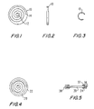
- FIG. 1 is a front view of an embodiment of the invention
- FIG. 2 is a lateral view of the embodiment of the invention shown in FIG. 1 ;
- FIG. 3 is a lateral view of an embodiment of the invention of FIG. 1 folded for delivery;
- FIG. 4 is a front view of another embodiment of the invention.
- FIG. 5 is a lateral view of a yet further embodiment of the invention.
- FIGS. 6 and 7 are each a lateral view of an embodiment of the invention with an anchoring mechanism
- FIG. 8 is an exploded schematic representation of construction of one embodiment of a sensor
- FIG. 9 is a schematic representation of an embodiment of the invention with distributed capacitance
- FIGS. 10 and 11 are each a schematic, partial cross-sectional view of an embodiment of a sensor according to the invention.
- FIG. 12 is a schematic representation of an alternate shape for an embodiment of the invention.
- FIG. 13 is a cross-sectional view of the distal end of a delivery catheter with the embodiment shown in FIG. 12 ;
- FIG. 14 is a schematic of another sensor according to the invention.
- FIG. 15 is a drawing of a read-out device employed according to the invention.
- FIG. 16 is a block diagram of an electrical circuit useful according to the invention.
- FIGS. 1 , 2 , and 3 One embodiment of a sensor according to the invention is shown in FIGS. 1 , 2 , and 3 , where a disc-shaped sensor 10 comprises a capacitor disk 12 and a wire spiral 14 .
- FIG. 2 is a lateral view of sensor 10
- FIG. 3 is a lateral view of sensor 10 in a folded configuration for insertion.
- the fact that sensor 10 is sufficiently flexible to be folded as shown in FIG. 4 is an important aspect of the invention.
- a ring 20 comprised of a shape memory alloy such as nitinol has been attached to, for example, with adhesive, or incorporated into, for example, layered within, a sensor 22 .
- FIG. 5 is a lateral cross-sectional view of a circular sensor 30 having a ring 32 comprised of a shape memory alloy such as nitinol encompassing the outer edge 34 of sensor 30 .
- Ring 32 preferably is attached to outer edge 34 by a suitable physiologically acceptable adhesive 36 , such as an appropriate epoxy or cyanoacrylate material.
- a suitable physiologically acceptable adhesive 36 such as an appropriate epoxy or cyanoacrylate material.
- the ring will be radiopaque.
- the size of the circular sensors of the invention will vary according to factors such as the intended application, the delivery system, etc.
- the circular sensors are intended to be from about 0.5 to about 3 cm in diameter, with a thickness of from about 0.05 to about 0.30 in.
- the thickness of the ring i.e., the width of the outside surface 38 , will preferably be from about 1.5 to about 3.5 times the thickness of the sensor.
- FIGS. 6 and 7 each represent a lateral view of a sensor with an anchoring member.
- sensor 40 has a screw/coil 42
- sensor 40 has an anchor 44 with umbrella-like projections 46 .
- anchor 42 or 44 When pressure is applied to the flat side 48 of sensor 40 , anchor 42 or 44 will penetrate a vessel wall, organ wall, or other substrate to cause sensor 36 to remain in a desired position or location.
- an anchoring mechanism such as is shown in FIGS. 6 and 7 could be attached to ring 32 in FIG. 5 .
- the pressure sensor of the invention can be manufactured using Micro-machining techniques that were developed for the integrated circuit industry.
- An example of this type of sensor features an inductive-capacitive (LC) resonant circuit with a variable capacitor, as is described in Allen et al., U.S. Pat. No. 6,111,520, all of which is incorporated herein by reference.
- the sensor contains two types of passive electrical components, namely, an inductor and a capacitor.
- the sensor is constructed so that the fluid pressure at the sensor's surface changes the distance between the capacitor's parallel plates and causes a variation of the sensor's capacitance.
- the sensor of the invention is constructed by laminating several layers of material together, as shown, for example, in FIG. 8 .
- a first layer 242 is fabricated from a sheet of polyimide film (e.g. KAPTON, available from Du Pont) upon which a micro-machined copper pattern 244 is deposited. Pattern 244 preferably consists of a circular conductive segment in the center of the sheet surrounded by a spiral coil.
- a second layer 248 comprises a sheet of flexible adhesive through which hole 250 has been cut in the center. (Optionally there may be more than one such layer 248 .)
- a final layer 252 is another sheet of polyimide film with a copper pattern 254 that is a mirror image of pattern 244 .
- the first, second, and third layers are aligned such that the holes in the middle adhesive layers are centered between the circular conductive segments in the middle of the two outer polyimide layers 242 and 252 .
- a capacitor defined as an electric circuit element used to store charge temporarily, consisting in general of two metallic plates separated and insulated from each other by a dielectric
- the two metal spirals on the polyimide sheets 242 and 252 form an inductor component of a miniature electrical circuit.
- the sensor exhibits the electrical characteristics associated with a standard LC circuit.
- An LC circuit is simply a closed loop with only two elements, a capacitor and an inductor. If a current is induced in the LC loop, the energy in the circuit is shared back and forth between the inductor and capacitor. The result is an energy oscillation that will vary at a specific frequency. This is termed the resonant frequency of the circuit and it can be easily calculated as its value is dependent on the circuit's inductance and capacitance. Therefore, a change in capacitance will cause the frequency to shift higher or lower in linear proportion to the change in the value of capacitance.
- the capacitor in the assembled pressure sensor consists of the two circular conductive segments separated by an air gap. If a pressure force is exerted on these segments it will act to deform the outer polyimide sheet and move the two conductive segments closer together. This will have the effect of reducing the air gap between them which will consequently change the capacitance of the circuit. The result will be a shift in the circuit's resonant frequency that will be in direct proportion to the force applied to the sensor's surface.
- the inductor Because of the presence of the inductor, it is possible to electromagnetically couple to the sensor and induce a current in the circuit. This allows for wireless communication with the sensor and the ability to operate it without the need for an internal source of energy such as a battery.
- the sensor if the sensor is located within the chamber of the heart, it will be possible to determine the pressure within the chamber in a simple, non-invasive procedure by remotely interrogating the sensor, recording the resonant frequency and converting this value to a pressure measurement.
- the readout device generates electromagnetic energy that penetrates through the body's tissues to the sensor's implanted location.
- the sensor's electrical components absorb a fraction of the electromagnetic energy that is generated by the readout device via inductive coupling.
- This coupling induces a current in the sensor's circuit oscillates at the same frequency as the applied electromagnetic energy. Due to the nature of the sensor's electromechanical system there exists a frequency of alternating current at which the absorption of energy from the readout device is at a minimum. This frequency is a function of the capacitance of the device. Therefore, if the sensor's capacitance changes, so will the frequency at which it minimally absorbs energy from the readout device. Since the sensor's capacitance is mechanically linked to the fluid pressure at the sensor's surface, a measurement of this frequency by the readout device gives a relative measurement of the fluid pressure. If calibration of the device is performed, then an absolute measurement of pressure can be made. See, for example, the extensive discussion in the Allen et al. patent, again incorporated herein by reference, as well as Gershenfeld et al., U.S. Pat. No. 6,025,725, incorporated herein by reference.
- the pressure sensor is made of completely passive components having no active circuitry or power sources such as batteries.
- the pressure sensor is completely self-contained having no leads to connect to an external circuit or power source. Furthermore, these same manufacturing techniques can be used to add additional sensing capabilities, such as the ability to measure temperature by the addition of a resistor to the basic LC circuit.
- the capacitor element consists of two plates that are separated by a suitable dielectric material, such as air, inert gas, fluid or a vacuum.
- a suitable dielectric material such as air, inert gas, fluid or a vacuum.
- various coatings could be applied to the surface or between the polymeric layers used to form the sensor. These coating can be used to provide a hermetic seal that will prevent leakage of body fluids into the cavity or permeation of the cavity material (gas, vacuum or fluid) out of the sensor.
- a sensor 270 has a multitude of capacitors 272 formed either as separate elements or as an array. In such a distributed capacitance configuration, there can be a more accurate and more sensitive measurement of pressure.
- the frequency response to the sensor will be in the range of from about 1 to about 200 MH z , preferably from about 1 to about 100 MH z , and more preferably from about 2 to about 90 MH z , with a Q factor from about 5 to about 80, preferably from about 10 to about 70, more preferably from about 10 to 60.
- the device is constructed using multiple layers upon lie the necessary circuit elements. Disposed on the top and bottom layer are metal patterns constructed using micro-machining techniques which define a top and bottom conductor and a spiral inductor coil. To provide for an electrical contact between the top and bottom layers small vias or holes are cut through the middle layers. When the layers are assembled, a metal paste is forced into the small vias to create direct electrical connections or conduits.
- a vialess operational LC circuit can be created. This absence of via holes represents a significant improvement to the sensor in that it simplifies the manufacturing process and, more importantly, significantly increases the durability of the sensor making it more appropriate for use inside the human body.
- FIG. 10 is a partial cross-sectional review of the sensor shown in FIG. 8 , where first layer 242 , second layer 248 , and third layer 252 are sandwiched together.
- a cylindrical space 256 comprises a pressure sensitive capacitor. No via holes are present.
- the sensor 278 shown in FIG. 11 comprises a first polyimide layer 280 , a second, adhesive layer 282 , and a third, polyimide layer 284 .
- First layer 280 has a copper pattern comprising a coil 286 and a disk 288
- third layer 284 comprises a coil 290 and a disk 292 .
- a cylindrical space 296 comprises a pressure sensitive capacitor.
- a diode 294 connected between coils 286 and 290 creates a non-linear sensor, i.e., a sensor where the frequency change is non-linear as compared to a change in pressure.
- the design of the sensor is not limited to a specific geometric configuration.
- the inductor component is described as a spiral coil.
- Other embodiments of the sensor could utilize oval, rectangular or an amorphous shape.
- Specific electrical, mechanical and biologic advantages could be obtained by employing these various geometric designs.
- a rectangular shaped sensor in which the ratio of length to width was greater than four would greater lend itself to catheter based delivery as is would minimize the radius of curvature required to position the folded device within a small diameter catheter.
- a more elaborate shape such as one resembling the petals of a flower, would lend itself to more complex folding patterns that could facilitate delivery to specific areas of a chamber of the heart.
- a foldable sensor is delivered to the chamber of a patient's heart in the distal end of a delivery catheter.
- the sensor can be regularly or irregularly shaped so that outer portions of the sensor can fold to about a 90° angle as compared to a relatively flat, middle portion of the sensor.
- a daisy or flower-shaped sensor 308 has a capacitor surface 310 connected to a wire 312 that partly follows the outer configuration of sensor 308 .
- Petals 314 fold so that sensor 308 with a distal anchor 316 can be “loaded” into a catheter 318 , as shown in FIG. 13 .
- a pushing rod member 322 is pushed distally to cause sensor 308 to be released from catheter 318 and attach to the inner surface of the wall of a heart chamber (not shown).
- rod member 322 will be temporarily affixed to sensor 308 for at least two purposes. First, rod member 322 functions as a safety or tether wire. And second, rod member 322 will be capable of twisting or otherwise maneuvering sensor 308 so that anchor 368 will attach to the heart chamber wall. Once sensor 308 is attached, rod member 322 is disengaged from sensor 308 and withdrawn proximally.
- FIG. 14 Another, embodiment of a sensor is shown in FIG. 14 , where circular sensor 330 comprises flexible cut-outs 332 .
- the first outer layer 334 comprises a polymide substrate with a copper pattern comprising a coil 340 and several, from 2 to 6, disks 342 to form pressure sensitive capacitors.
- Sensor 330 also comprises at least one adhesive layer (not shown) and a third outer layer corresponding to the first outer layer (not shown).
- sensor 330 has at least one diode connecting the copper coils of the first and third layers.
- the flexible cut-outs 352 facilitate, among other things, folding of sections of sensor 370 for placement in, or arrangement upon, a delivery catheter, such as in FIG. 13 .
- the sections can also be folded to create either a “Z” shape or, for example, a “U” shape, for other applications. It is within the scope of the invention that variously numbered and shaped cut-outs could be used for particular applications.
- the invention is not limited to the implantation of a single sensor. Since the biological environment within a patient's heart is not necessarily homogeneous, multiple pressure sensors may be introduced into a patient's heart, each being positioned at different locations. In this situation, each sensor may be designed with a unique signature (obtained by changing the resonant frequency of the sensor), so that the pressure measurement derived from one sensor can be localized to its specific position within the heart.
- the pressure sensor When introduced into the chamber of a patient's heart, the pressure sensor can provide pressure related data by use of an external measuring device.
- an external measuring device As disclosed in the Allen et al. patent, several different excitation systems can be used.
- the readout device generates electromagnetic energy that can penetrate through the body's tissues to the sensor's implanted location.
- the sensor's electrical components can absorb a fraction of the electromagnetic energy that is generated by the readout device via inductive coupling. This coupling will induce a current in the sensor's circuit that will oscillate at the same frequency as the applied electromagnetic energy. Due to the nature of the sensor's electromechanical system there will exist a frequency of alternating current at which the absorption of energy from the readout device is at a minimum. This frequency is a function of the capacitance of the device.
- the sensor's capacitance changes so will the frequency at which it minimally absorbs energy from the readout device. Since the sensor's capacitance is mechanically linked to the fluid pressure at the sensor's surface, a measurement of this frequency by the readout device can give a relative measurement of the fluid pressure. If calibration of the device is performed then an absolute measurement of pressure can be made
- the circuitry used to measure and display pressure is contained within a simple to operate, battery powered, hand-held electronic unit 400 , as shown in FIG. 15 .
- This unit 400 also contains the antenna 402 needed to perform the electromagnetic coupling to the sensor.
- the antenna may be integrated into the housing for the electronics or it may be detachable from the unit so that it can be positioned on the surface of the body 404 in proximity to the implanted sensor and easily moved to optimize the coupling between antenna and sensor.
- the antenna itself may consist of a simple standard coil configuration or my incorporate ferrous elements to maximize the coupling efficiency.
- the electronic device would feature an LCD or LED display 406 designed to clearly display the recorded pressure in physiologically relevant units such as mm HG.
- the display may be created by integrating a commercially available hand-held computing device such as a Palm® or micro-PC into the electronic circuitry and using this device's display unit as the visual interface between the equipment and its operator.
- a commercially available hand-held computing device such as a Palm® or micro-PC
- the hand-held computer could be detached from the read-out unit and linked to a standard desktop computer. The information from the device could thus be downloaded into any of several commercially available data acquisition software programs for more detailed analysis or for electronic transfer via hard media or the internet to a remote location.
- the present invention provides for an impedance system and method of determining the resonant frequency and bandwidth of a resonant circuit within a particular sensor.
- the system includes a transmitting antenna, which is coupled to an impedance analyzer.
- the impedance analyzer applies a constant voltage signal to the transmitting antenna scanning the frequency across a predetermined spectrum.
- the current passing through the transmitting antenna experiences a peak at the resonant frequency of the sensor.
- the resonant frequency and bandwidth are thus determined from this peak in the current.
- the method of determining the resonant frequency and bandwidth using an impedance approach may include the steps of transmitting an excitation signal using a transmitting antenna and electromagnetically coupling a sensor having a resonant circuit to the transmitting antenna thereby modifying the impedance of the transmitting antenna. Next, the step of measuring the change in impedance of the transmitting antenna is performed, and finally, the resonant frequency and bandwidth of the sensor circuit are determined.
- the present invention provides for a transmit and receive system and method for determining the resonant frequency and bandwidth of a resonant circuit within a particular sensor.
- an excitation signal of white noise or predetermined multiple frequencies is transmitted from a transmitting antenna, the sensor being electromagnetically coupled to the transmitting antenna.
- a current is induced in the resonant circuit of the sensor as it absorbs energy from the transmitted excitation signal, the current oscillating at the resonant frequency of the resonant circuit.
- a receiving antenna also electromagnetically coupled to the transmitting antenna, receives the excitation signal minus the energy which was absorbed by the sensor.
- the power of the received signal experiences a dip or notch at the resonant frequency of the sensor.
- the resonant frequency and bandwidth are determined from this notch in the power.
- the transmit and receive method of determining the resonant frequency and bandwidth of a sensor circuit includes the steps of transmitting a multiple frequency signal from transmitting antenna, and, electromagnetically coupling a resonant circuit on a sensor to the transmitting antenna thereby inducing a current in the sensor circuit. Next, the step of receiving a modified transmitted signal due to the induction of current in the sensor circuit is performed. Finally, the step of determining the resonant frequency and bandwidth from the received signal is executed.
- Yet another system and method for determining the resonant frequency and bandwidth of a resonant circuit within a particular sensor includes a chirp interrogation system.
- This system provides for a transmitting antenna which is electromagnetically coupled to the resonant circuit of the sensor.
- An excitation signal of white noise or predetermined multiple frequencies is applied to the transmitting antenna for a predetermined period of time, thereby inducing a current in the resonant circuit of the sensor at the resonant frequency.
- the system listens for a return signal which radiates from the sensor.
- the resonant frequency and bandwidth of the resonant circuit are determined from the return signal.
- the chirp interrogation method for determining the resonant frequency and bandwidth of a resonant circuit within a particular sensor includes the steps of transmitting a multi-frequency signal pulse from a transmitting antenna, electromagnetically coupling a resonant circuit on a sensor to the transmitting antenna thereby inducing a current in the sensor circuit, listening for and receiving a return signal radiated from the sensor circuit, and determining the resonant frequency and bandwidth from the return signal.
- a transmitter and receiver i.e., a transceiver 422
- Transceiver 422 is an electronic or digital connection with a phase detector 430 , a microprocessor 432 , and a frequency synthesizer 434 .
- Microprocessor 432 is in turn connected to an interface 436 such as a terminal.
- Power supply 438 regulates and provides electrical power to the system.
- the present invention also provides an analog system and method for determining the resonant frequency of a resonant circuit within a particular sensor.
- the analog system comprises a transmitting antenna coupled as part of a tank circuit which in turn is coupled to an oscillator.
- a signal is generated which oscillates at a frequency determined by the electrical characteristics of the tank circuit.
- the frequency of this signal is further modified by the electromagnetic coupling of the resonant circuit of a sensor.
- This signal is applied to a frequency discriminator which in turn provides a signal from which the resonant frequency of the sensor circuit is determined.
- the analog method for determining the resonant frequency and bandwidth of a resonant circuit within a particular sensor includes the steps of generating a transmission signal using a tank circuit which includes a transmitting antenna, modifying the frequency of the transmission signal by electromagnetically coupling the resonant circuit of a sensor to the transmitting antenna, and converting the modified transmission signal into a standard signal for further application.
- the invention further includes an alternative method of measuring pressure in which a non-linear element such as a diode or polyvinylidenedifloride piezo-electric polymer is added to the LC circuit.
- a non-linear element such as a diode or polyvinylidenedifloride piezo-electric polymer is added to the LC circuit.
- a diode with a low turn-on voltage such as a Schottky diode can be fabricated using micro-machining techniques.
- the presence of this non-linear element in various configurations within the LC circuit can be used to modulate the incoming signal from the receiving device and produce different harmonics of the original signal.
- the read-out circuitry can be tuned to receive the particular harmonic frequency that is produced and use this signal to reconstruct the fundamental frequency of the sensor.
- the advantage of this approach is two-fold; the incoming signal can be transmitted continuously and since the return signal will be at different signals, the return signal can also be received continuously.
- One additional concern regarding devices designated for long term implantation in the human body is maintenance of electrical stability over time as the environment the sensor has been placed in changes. Under this scenario the sensor's accuracy may drift from its original baseline. It would thus be desirable to have available to the user of the device, a method for determining if the sensor is functioning properly and also to be able to recalibrate the device anytime after it has been implanted.
- This invention therefore also includes a method of using acoustic energy to challenge the sensor and determining to what degree (if any) sensor performance has been degraded. In this method, energy in the ultrasound range is directed towards the sensor and a measurement is made of the mechanical resonance of the sensor membrane. This same measurement can be made at point after the sensor has been implanted.
- a determination of the degree of change in mechanical resonance frequency can be established. This value can then be used to create a calibration factor that can be applied to the pressure reading taken post-implantation in order to adjust the measured value to reflect the actual pressure within the heart chamber.
Abstract
Description
-
- that is offset from the main axis of the outer tube, the sensor will be biased into a planar configuration as it is forced through the slit during the deployment process.
Claims (32)
Priority Applications (1)
| Application Number | Priority Date | Filing Date | Title |
|---|---|---|---|
| US10/886,829 US7481771B2 (en) | 2002-01-22 | 2004-07-07 | Implantable wireless sensor for pressure measurement within the heart |
Applications Claiming Priority (2)
| Application Number | Priority Date | Filing Date | Title |
|---|---|---|---|
| US10/054,672 US6855115B2 (en) | 2002-01-22 | 2002-01-22 | Implantable wireless sensor for pressure measurement within the heart |
| US10/886,829 US7481771B2 (en) | 2002-01-22 | 2004-07-07 | Implantable wireless sensor for pressure measurement within the heart |
Related Parent Applications (1)
| Application Number | Title | Priority Date | Filing Date |
|---|---|---|---|
| US10/054,672 Continuation US6855115B2 (en) | 2002-01-22 | 2002-01-22 | Implantable wireless sensor for pressure measurement within the heart |
Publications (2)
| Publication Number | Publication Date |
|---|---|
| US20050015014A1 US20050015014A1 (en) | 2005-01-20 |
| US7481771B2 true US7481771B2 (en) | 2009-01-27 |
Family
ID=21992728
Family Applications (2)
| Application Number | Title | Priority Date | Filing Date |
|---|---|---|---|
| US10/054,672 Expired - Lifetime US6855115B2 (en) | 2002-01-22 | 2002-01-22 | Implantable wireless sensor for pressure measurement within the heart |
| US10/886,829 Expired - Fee Related US7481771B2 (en) | 2002-01-22 | 2004-07-07 | Implantable wireless sensor for pressure measurement within the heart |
Family Applications Before (1)
| Application Number | Title | Priority Date | Filing Date |
|---|---|---|---|
| US10/054,672 Expired - Lifetime US6855115B2 (en) | 2002-01-22 | 2002-01-22 | Implantable wireless sensor for pressure measurement within the heart |
Country Status (2)
| Country | Link |
|---|---|
| US (2) | US6855115B2 (en) |
| WO (1) | WO2003061467A1 (en) |
Cited By (88)
| Publication number | Priority date | Publication date | Assignee | Title |
|---|---|---|---|---|
| US20050165317A1 (en) * | 2003-11-04 | 2005-07-28 | Turner Nicholas M. | Medical devices |
| US20060047205A1 (en) * | 2002-10-07 | 2006-03-02 | Integrated Sensing Systems, Inc. | Delivery method and system for monitoring cardiovascular pressures |
| US20060122683A1 (en) * | 2004-12-07 | 2006-06-08 | Scimed Life Systems, Inc. | Medical device that signals lumen loss |
| US20070049929A1 (en) * | 2005-05-20 | 2007-03-01 | Catanese Joseph Iii | Apparatus and method for manipulating or retracting tissue and anatomical structure |
| US20070060959A1 (en) * | 2005-09-09 | 2007-03-15 | Cardiac Pacemakers, Inc. | Using implanted sensors for feedback control of implanted medical devices |
| US20070075905A1 (en) * | 2005-10-05 | 2007-04-05 | Kenergy, Inc. | Radio frequency antenna for a wireless intravascular medical device |
| US20070142728A1 (en) * | 2003-04-14 | 2007-06-21 | Avi Penner | Apparatus and methods using acoustic telemetry for intrabody communications |
| US20080015421A1 (en) * | 2000-10-16 | 2008-01-17 | Remon Medical Technologies, Ltd. | Barometric pressure correction based on remote sources of information |
| US20080077440A1 (en) * | 2006-09-26 | 2008-03-27 | Remon Medical Technologies, Ltd | Drug dispenser responsive to physiological parameters |
| US20080082005A1 (en) * | 2006-07-05 | 2008-04-03 | Stern David R | Method for Using a Wireless Pressure Sensor to Monitor Pressure Inside the Human Heart |
| US20080312553A1 (en) * | 2007-06-14 | 2008-12-18 | Timmons Michael J | Intracorporeal pressure measurement devices and methods |
| US20090024042A1 (en) * | 2007-07-03 | 2009-01-22 | Endotronix, Inc. | Method and system for monitoring ventricular function of a heart |
| US20090157147A1 (en) * | 2007-11-26 | 2009-06-18 | Microtransponder, Inc., | Implantable Transponder Systems and Methods |
| US20090177251A1 (en) * | 2008-01-07 | 2009-07-09 | Paul Huelskamp | System And Method For In Situ Trimming Of Oscillators In A Pair Of Implantable Medical Devices |
| US20090198307A1 (en) * | 2008-02-06 | 2009-08-06 | Bin Mi | Direct inductive/acoustic converter for implantable medical device |
| US20090198293A1 (en) * | 2003-12-19 | 2009-08-06 | Lawrence Cauller | Microtransponder Array for Implant |
| US20090201148A1 (en) * | 2008-02-12 | 2009-08-13 | Tran Binh C | Systems and methods for controlling wireless signal transfers between ultrasound-enabled medical devices |
| US20090204163A1 (en) * | 2008-02-11 | 2009-08-13 | Shuros Allan C | Methods of monitoring hemodynamic status for rhythm discrimination within the heart |
| US20100042177A1 (en) * | 2008-08-14 | 2010-02-18 | Cardiac Pacemakers, Inc. | Performance assessment and adaptation of an acoustic communication link |
| US20100094144A1 (en) * | 2008-10-10 | 2010-04-15 | Eyal Doron | Systems and methods for determining cardiac output using pulmonary artery pressure measurements |
| US20100125211A1 (en) * | 2008-11-19 | 2010-05-20 | Stahmann Jeffrey E | Assessment of pulmonary vascular resistance via pulmonary artery pressure |
| US7813808B1 (en) | 2004-11-24 | 2010-10-12 | Remon Medical Technologies Ltd | Implanted sensor system with optimized operational and sensing parameters |
| US20100324378A1 (en) * | 2009-06-17 | 2010-12-23 | Tran Binh C | Physiologic signal monitoring using ultrasound signals from implanted devices |
| US20110036173A1 (en) * | 2008-04-30 | 2011-02-17 | Senseor | Remotely addressable pressure and/or temperature measuring device installed in a biological medium |
| US7918800B1 (en) * | 2004-10-08 | 2011-04-05 | Endovascular Technologies, Inc. | Aneurysm sensing devices and delivery systems |
| US8043309B2 (en) | 2005-05-20 | 2011-10-25 | Neotract, Inc. | Devices, systems and methods for retracting, lifting, compressing, supporting or repositioning tissues or anatomical structures |
| US8157815B2 (en) | 2005-05-20 | 2012-04-17 | Neotract, Inc. | Integrated handle assembly for anchor delivery system |
| US8216254B2 (en) | 2005-05-20 | 2012-07-10 | Neotract, Inc. | Anchor delivery system with replaceable cartridge |
| US8271093B2 (en) | 2004-09-17 | 2012-09-18 | Cardiac Pacemakers, Inc. | Systems and methods for deriving relative physiologic measurements using a backend computing system |
| US8401643B2 (en) | 2011-05-17 | 2013-03-19 | Medtronic Vascular, Inc. | Implantable medical sensor and anchoring system |
| US8475372B2 (en) | 2010-10-29 | 2013-07-02 | Medtronic Vascular, Inc. | Implantable medical sensor and fixation system |
| US8489185B2 (en) | 2008-07-02 | 2013-07-16 | The Board Of Regents, The University Of Texas System | Timing control for paired plasticity |
| US8491606B2 (en) | 2005-05-20 | 2013-07-23 | Neotract, Inc. | Median lobe retraction apparatus and method |
| US8529584B2 (en) | 2005-05-20 | 2013-09-10 | Neotract, Inc. | Median lobe band implant apparatus and method |
| US8628542B2 (en) | 2005-05-20 | 2014-01-14 | Neotract, Inc. | Median lobe destruction apparatus and method |
| US8727996B2 (en) | 2011-04-20 | 2014-05-20 | Medtronic Vascular, Inc. | Delivery system for implantable medical device |
| US8734468B2 (en) | 2005-05-20 | 2014-05-27 | Neotract, Inc. | Devices, systems and methods for treating benign prostatic hyperplasia and other conditions |
| US8834492B2 (en) | 2005-05-20 | 2014-09-16 | Neotract, Inc. | Continuous indentation lateral lobe apparatus and method |
| US8864676B2 (en) | 2010-10-29 | 2014-10-21 | Medtronic Vascular, Inc. | Implantable medical sensor and fixation system |
| US8945152B2 (en) | 2005-05-20 | 2015-02-03 | Neotract, Inc. | Multi-actuating trigger anchor delivery system |
| US8989867B2 (en) | 2011-07-14 | 2015-03-24 | Cyberonics, Inc. | Implantable nerve wrap for nerve stimulation configured for far field radiative powering |
| US9078613B2 (en) | 2007-08-23 | 2015-07-14 | Purdue Research Foundation | Intra-occular pressure sensor |
| US9082695B2 (en) | 2011-06-06 | 2015-07-14 | Avalanche Technology, Inc. | Vialess memory structure and method of manufacturing same |
| US9161749B2 (en) | 2011-04-14 | 2015-10-20 | Neotract, Inc. | Method and apparatus for treating sexual dysfunction |
| US9198908B2 (en) | 2013-03-15 | 2015-12-01 | St. Jude Medical Luxembourg Holdings Ii S.A.R.L. (“Sjm Lux Ii”) | Methods for the treatment of cardiovascular conditions |
| US9307905B2 (en) | 2012-09-14 | 2016-04-12 | University Of Washington | Intraocular pressure sensing devices and associated systems and methods |
| US9314584B1 (en) | 2011-06-27 | 2016-04-19 | Bayer Healthcare Llc | Method and apparatus for fractional flow reserve measurements |
| US9320511B2 (en) | 2005-05-20 | 2016-04-26 | Neotract, Inc. | Multi-actuating trigger anchor delivery system |
| US9333365B2 (en) | 2010-07-30 | 2016-05-10 | Medtronic, Inc. | Antenna for an implantable medical device |
| US9351648B2 (en) | 2012-08-24 | 2016-05-31 | Medtronic, Inc. | Implantable medical device electrode assembly |
| US9492678B2 (en) | 2011-07-14 | 2016-11-15 | Cyberonics, Inc. | Far field radiative powering of implantable medical therapy delivery devices |
| US9504461B2 (en) | 2005-05-20 | 2016-11-29 | Neotract, Inc. | Anchor delivery system |
| US9522282B2 (en) | 2012-03-29 | 2016-12-20 | Cyberonics, Inc. | Powering multiple implantable medical therapy delivery devices using far field radiative powering at multiple frequencies |
| US9536122B2 (en) | 2014-11-04 | 2017-01-03 | General Electric Company | Disposable multivariable sensing devices having radio frequency based sensors |
| US9538657B2 (en) | 2012-06-29 | 2017-01-03 | General Electric Company | Resonant sensor and an associated sensing method |
| US9549739B2 (en) | 2005-05-20 | 2017-01-24 | Neotract, Inc. | Devices, systems and methods for treating benign prostatic hyperplasia and other conditions |
| US9589686B2 (en) | 2006-11-16 | 2017-03-07 | General Electric Company | Apparatus for detecting contaminants in a liquid and a system for use thereof |
| US9610450B2 (en) | 2010-07-30 | 2017-04-04 | Medtronics, Inc. | Antenna for an implantable medical device |
| US9638653B2 (en) | 2010-11-09 | 2017-05-02 | General Electricity Company | Highly selective chemical and biological sensors |
| US9658178B2 (en) | 2012-09-28 | 2017-05-23 | General Electric Company | Sensor systems for measuring an interface level in a multi-phase fluid composition |
| US9675809B2 (en) | 2011-07-14 | 2017-06-13 | Cyberonics, Inc. | Circuit, system and method for far-field radiative powering of an implantable medical device |
| US9717422B2 (en) | 2012-12-12 | 2017-08-01 | Volcano Corporation | Sheath with optically interrogatable sensors |
| US9746452B2 (en) | 2012-08-22 | 2017-08-29 | General Electric Company | Wireless system and method for measuring an operative condition of a machine |
| US9757591B2 (en) | 2013-02-11 | 2017-09-12 | Bayer Healthcare Llc | Methods and systems for monitoring an automated infusion system |
| US10130353B2 (en) | 2012-06-29 | 2018-11-20 | Neotract, Inc. | Flexible system for delivering an anchor |
| US10195014B2 (en) | 2005-05-20 | 2019-02-05 | Neotract, Inc. | Devices, systems and methods for treating benign prostatic hyperplasia and other conditions |
| US10265061B2 (en) | 2005-05-20 | 2019-04-23 | Neotract, Inc. | Latching anchor device |
| US10292801B2 (en) | 2012-03-29 | 2019-05-21 | Neotract, Inc. | System for delivering anchors for treating incontinence |
| US10299780B2 (en) | 2005-05-20 | 2019-05-28 | Neotract, Inc. | Apparatus and method for manipulating or retracting tissue and anatomical structure |
| US10598650B2 (en) | 2012-08-22 | 2020-03-24 | General Electric Company | System and method for measuring an operative condition of a machine |
| WO2020081427A2 (en) | 2018-10-16 | 2020-04-23 | Pacesetter, Inc. | Apparatus and method for sensor deployment and fixation |
| US10684268B2 (en) | 2012-09-28 | 2020-06-16 | Bl Technologies, Inc. | Sensor systems for measuring an interface level in a multi-phase fluid composition |
| US10709341B2 (en) | 2012-11-21 | 2020-07-14 | St. Jude Medical Luxembourg Holdings II S.a.r.l. | Devices, systems, and methods for pulmonary arterial hypertension (PAH) assessment and treatment |
| US10806428B2 (en) | 2015-02-12 | 2020-10-20 | Foundry Innovation & Research 1, Ltd. | Implantable devices and related methods for heart failure monitoring |
| US10806352B2 (en) | 2016-11-29 | 2020-10-20 | Foundry Innovation & Research 1, Ltd. | Wireless vascular monitoring implants |
| US10814980B2 (en) | 2017-09-02 | 2020-10-27 | Precision Drone Services Intellectual Property, Llc | Distribution assembly for an aerial vehicle |
| US10914698B2 (en) | 2006-11-16 | 2021-02-09 | General Electric Company | Sensing method and system |
| US10925587B2 (en) | 2005-05-20 | 2021-02-23 | Neotract, Inc. | Anchor delivery system |
| US10993669B2 (en) | 2017-04-20 | 2021-05-04 | Endotronix, Inc. | Anchoring system for a catheter delivered device |
| US11039813B2 (en) | 2015-08-03 | 2021-06-22 | Foundry Innovation & Research 1, Ltd. | Devices and methods for measurement of Vena Cava dimensions, pressure and oxygen saturation |
| US11097090B2 (en) | 2014-01-27 | 2021-08-24 | President And Fellows Of Harvard College | Mechanical assist device |
| US11206992B2 (en) | 2016-08-11 | 2021-12-28 | Foundry Innovation & Research 1, Ltd. | Wireless resonant circuit and variable inductance vascular monitoring implants and anchoring structures therefore |
| US11298115B2 (en) | 2020-08-03 | 2022-04-12 | Teleflex Life Sciences Limited | Handle and cartridge system for medical interventions |
| US11564596B2 (en) | 2016-08-11 | 2023-01-31 | Foundry Innovation & Research 1, Ltd. | Systems and methods for patient fluid management |
| US11672520B2 (en) | 2017-12-23 | 2023-06-13 | Teleflex Life Sciences Limited | Expandable tissue engagement apparatus and method |
| US11701018B2 (en) | 2016-08-11 | 2023-07-18 | Foundry Innovation & Research 1, Ltd. | Wireless resonant circuit and variable inductance vascular monitoring implants and anchoring structures therefore |
| US11779238B2 (en) | 2017-05-31 | 2023-10-10 | Foundry Innovation & Research 1, Ltd. | Implantable sensors for vascular monitoring |
| US11944495B2 (en) | 2017-05-31 | 2024-04-02 | Foundry Innovation & Research 1, Ltd. | Implantable ultrasonic vascular sensor |
Families Citing this family (283)
| Publication number | Priority date | Publication date | Assignee | Title |
|---|---|---|---|---|
| US20030036746A1 (en) * | 2001-08-16 | 2003-02-20 | Avi Penner | Devices for intrabody delivery of molecules and systems and methods utilizing same |
| US9066695B2 (en) | 1998-04-30 | 2015-06-30 | Abbott Diabetes Care Inc. | Analyte monitoring device and methods of use |
| US8346337B2 (en) | 1998-04-30 | 2013-01-01 | Abbott Diabetes Care Inc. | Analyte monitoring device and methods of use |
| US6949816B2 (en) | 2003-04-21 | 2005-09-27 | Motorola, Inc. | Semiconductor component having first surface area for electrically coupling to a semiconductor chip and second surface area for electrically coupling to a substrate, and method of manufacturing same |
| US8688188B2 (en) | 1998-04-30 | 2014-04-01 | Abbott Diabetes Care Inc. | Analyte monitoring device and methods of use |
| US8465425B2 (en) | 1998-04-30 | 2013-06-18 | Abbott Diabetes Care Inc. | Analyte monitoring device and methods of use |
| US8480580B2 (en) | 1998-04-30 | 2013-07-09 | Abbott Diabetes Care Inc. | Analyte monitoring device and methods of use |
| US8974386B2 (en) | 1998-04-30 | 2015-03-10 | Abbott Diabetes Care Inc. | Analyte monitoring device and methods of use |
| US6175752B1 (en) | 1998-04-30 | 2001-01-16 | Therasense, Inc. | Analyte monitoring device and methods of use |
| US6764446B2 (en) | 2000-10-16 | 2004-07-20 | Remon Medical Technologies Ltd | Implantable pressure sensors and methods for making and using them |
| US7283874B2 (en) | 2000-10-16 | 2007-10-16 | Remon Medical Technologies Ltd. | Acoustically powered implantable stimulating device |
| US6560471B1 (en) | 2001-01-02 | 2003-05-06 | Therasense, Inc. | Analyte monitoring device and methods of use |
| EP1397068A2 (en) | 2001-04-02 | 2004-03-17 | Therasense, Inc. | Blood glucose tracking apparatus and methods |
| US7699059B2 (en) * | 2002-01-22 | 2010-04-20 | Cardiomems, Inc. | Implantable wireless sensor |
| US6855115B2 (en) * | 2002-01-22 | 2005-02-15 | Cardiomems, Inc. | Implantable wireless sensor for pressure measurement within the heart |
| NL1021054C1 (en) * | 2002-07-12 | 2004-01-13 | Best Medical Internat Beheer B | Universal measuring device for medical application. |
| CA2494989A1 (en) * | 2002-08-07 | 2004-02-19 | Cardiomems, Inc. | Implantable wireless sensor for blood pressure measurement within an artery |
| US7615010B1 (en) * | 2002-10-03 | 2009-11-10 | Integrated Sensing Systems, Inc. | System for monitoring the physiologic parameters of patients with congestive heart failure |
| US20040102806A1 (en) * | 2002-11-27 | 2004-05-27 | Scimed Life Systems, Inc. | Intravascular filter monitoring |
| WO2004056268A1 (en) * | 2002-12-19 | 2004-07-08 | Koninklijke Philips Electronics N.V. | Fabric-integrated conductivity sensor |
| WO2004075782A2 (en) * | 2003-02-26 | 2004-09-10 | Alfred, E. Mann Institute For Biomedical Engineering At The University Of Southern California | An implantable device with sensors for differential monitoring of internal condition |
| US20080146946A1 (en) * | 2003-03-28 | 2008-06-19 | Valentino Montegrande | Blood pressure sensor apparatus |
| US20060178583A1 (en) * | 2003-03-28 | 2006-08-10 | Valentino Montegrande | Blood pressure sensor apparatus |
| EP1673008B1 (en) * | 2003-09-12 | 2012-03-14 | Laborie Medical Technologies Inc. | Apparatus for medical measurement |
| US8026729B2 (en) | 2003-09-16 | 2011-09-27 | Cardiomems, Inc. | System and apparatus for in-vivo assessment of relative position of an implant |
| CA2539261C (en) | 2003-09-16 | 2011-05-17 | Cardiomems, Inc. | Implantable wireless sensor |
| US7245117B1 (en) | 2004-11-01 | 2007-07-17 | Cardiomems, Inc. | Communicating with implanted wireless sensor |
| US20060287602A1 (en) * | 2005-06-21 | 2006-12-21 | Cardiomems, Inc. | Implantable wireless sensor for in vivo pressure measurement |
| US7416530B2 (en) * | 2003-11-04 | 2008-08-26 | L & P 100 Limited | Medical devices |
| WO2005067817A1 (en) * | 2004-01-13 | 2005-07-28 | Remon Medical Technologies Ltd | Devices for fixing a sensor in a body lumen |
| US7471986B2 (en) * | 2004-02-20 | 2008-12-30 | Cardiac Pacemakers, Inc. | System and method for transmitting energy to and establishing a communications network with one or more implanted devices |
| US8337482B2 (en) * | 2004-04-19 | 2012-12-25 | The Invention Science Fund I, Llc | System for perfusion management |
| US8353896B2 (en) | 2004-04-19 | 2013-01-15 | The Invention Science Fund I, Llc | Controllable release nasal system |
| US7850676B2 (en) * | 2004-04-19 | 2010-12-14 | The Invention Science Fund I, Llc | System with a reservoir for perfusion management |
| US8024036B2 (en) * | 2007-03-19 | 2011-09-20 | The Invention Science Fund I, Llc | Lumen-traveling biological interface device and method of use |
| US20050234440A1 (en) * | 2004-04-19 | 2005-10-20 | Searete Llc, A Limited Liability Corporation Of The State Of Delaware | System with a sensor for perfusion management |
| US9011329B2 (en) * | 2004-04-19 | 2015-04-21 | Searete Llc | Lumenally-active device |
| US20070010868A1 (en) * | 2004-04-19 | 2007-01-11 | Searete Llc, A Limited Liability Corporation Of The State Of Delaware | Lumenally-active device |
| US8512219B2 (en) | 2004-04-19 | 2013-08-20 | The Invention Science Fund I, Llc | Bioelectromagnetic interface system |
| US20070244520A1 (en) * | 2004-04-19 | 2007-10-18 | Searete Llc | Lumen-traveling biological interface device and method of use |
| US7857767B2 (en) * | 2004-04-19 | 2010-12-28 | Invention Science Fund I, Llc | Lumen-traveling device |
| US8092549B2 (en) | 2004-09-24 | 2012-01-10 | The Invention Science Fund I, Llc | Ciliated stent-like-system |
| US8361013B2 (en) * | 2004-04-19 | 2013-01-29 | The Invention Science Fund I, Llc | Telescoping perfusion management system |
| US7998060B2 (en) * | 2004-04-19 | 2011-08-16 | The Invention Science Fund I, Llc | Lumen-traveling delivery device |
| WO2006052765A2 (en) | 2004-11-04 | 2006-05-18 | Smith & Nephew, Inc. | Cycle and load measurement device |
| WO2006048664A2 (en) * | 2004-11-04 | 2006-05-11 | L & P 100 Limited | Medical devices |
| US20060116602A1 (en) * | 2004-12-01 | 2006-06-01 | Alden Dana A | Medical sensing device and system |
| US7290454B2 (en) * | 2004-12-02 | 2007-11-06 | Honeywell International Inc. | Pressure flow sensor systems and pressure flow sensors for use therein |
| US7059195B1 (en) * | 2004-12-02 | 2006-06-13 | Honeywell International Inc. | Disposable and trimmable wireless pressure sensor for medical applications |
| US20060122522A1 (en) * | 2004-12-03 | 2006-06-08 | Abhi Chavan | Devices and methods for positioning and anchoring implantable sensor devices |
| US7585280B2 (en) | 2004-12-29 | 2009-09-08 | Codman & Shurtleff, Inc. | System and method for measuring the pressure of a fluid system within a patient |
| US10390714B2 (en) | 2005-01-12 | 2019-08-27 | Remon Medical Technologies, Ltd. | Devices for fixing a sensor in a lumen |
| US7601162B2 (en) * | 2005-01-14 | 2009-10-13 | Ethicon Endo-Surgery, Inc. | Actuator for an implantable band |
| US7879068B2 (en) | 2005-01-14 | 2011-02-01 | Ethicon Endo-Surgery, Inc. | Feedback sensing for a mechanical restrictive device |
| US7775966B2 (en) * | 2005-02-24 | 2010-08-17 | Ethicon Endo-Surgery, Inc. | Non-invasive pressure measurement in a fluid adjustable restrictive device |
| US7545272B2 (en) | 2005-02-08 | 2009-06-09 | Therasense, Inc. | RF tag on test strips, test strip vials and boxes |
| US7662653B2 (en) | 2005-02-10 | 2010-02-16 | Cardiomems, Inc. | Method of manufacturing a hermetic chamber with electrical feedthroughs |
| US7647836B2 (en) * | 2005-02-10 | 2010-01-19 | Cardiomems, Inc. | Hermetic chamber with electrical feedthroughs |
| US7658196B2 (en) | 2005-02-24 | 2010-02-09 | Ethicon Endo-Surgery, Inc. | System and method for determining implanted device orientation |
| US7699770B2 (en) * | 2005-02-24 | 2010-04-20 | Ethicon Endo-Surgery, Inc. | Device for non-invasive measurement of fluid pressure in an adjustable restriction device |
| US7775215B2 (en) | 2005-02-24 | 2010-08-17 | Ethicon Endo-Surgery, Inc. | System and method for determining implanted device positioning and obtaining pressure data |
| US7927270B2 (en) | 2005-02-24 | 2011-04-19 | Ethicon Endo-Surgery, Inc. | External mechanical pressure sensor for gastric band pressure measurements |
| US8016744B2 (en) * | 2005-02-24 | 2011-09-13 | Ethicon Endo-Surgery, Inc. | External pressure-based gastric band adjustment system and method |
| US8066629B2 (en) | 2005-02-24 | 2011-11-29 | Ethicon Endo-Surgery, Inc. | Apparatus for adjustment and sensing of gastric band pressure |
| US8021307B2 (en) | 2005-03-03 | 2011-09-20 | Cardiomems, Inc. | Apparatus and method for sensor deployment and fixation |
| US8118749B2 (en) * | 2005-03-03 | 2012-02-21 | Cardiomems, Inc. | Apparatus and method for sensor deployment and fixation |
| WO2006096582A1 (en) * | 2005-03-04 | 2006-09-14 | Cardiomems, Inc. | Communicating with an implanted wireless sensor |
| US20060211945A1 (en) * | 2005-03-15 | 2006-09-21 | Codman & Shurtleff, Inc. | Pressure sensing methods |
| US7510533B2 (en) * | 2005-03-15 | 2009-03-31 | Codman & Shurtleff, Inc. | Pressure sensing valve |
| US10362947B2 (en) * | 2005-03-15 | 2019-07-30 | Integra LifeSciences Switzerland Sarl | Pressure sensing devices |
| AU2006235474A1 (en) | 2005-04-12 | 2006-10-19 | Cardiomems, Inc. | Electromagnetically coupled hermetic chamber |
| EP1893080A2 (en) | 2005-06-21 | 2008-03-05 | CardioMems, Inc. | Method of manufacturing implantable wireless sensor for in vivo pressure measurement |
| US7621036B2 (en) * | 2005-06-21 | 2009-11-24 | Cardiomems, Inc. | Method of manufacturing implantable wireless sensor for in vivo pressure measurement |
| AU2012247061B2 (en) * | 2005-06-21 | 2014-07-17 | Cardiomems, Inc. | Implantable wireless sensor for in vivo pressure measurement |
| JP2008543513A (en) * | 2005-06-27 | 2008-12-04 | センス エー/エス | Blood pressure determination method and apparatus |
| EP1902529B1 (en) | 2005-07-08 | 2012-06-13 | CardioMems, Inc. | Coupling loop, cable assembly and method for positioning coupling loop |
| US7162926B1 (en) | 2005-08-04 | 2007-01-16 | Kavlico Corporation | Lead embedded pressure sensor |
| AU2006282828B2 (en) | 2005-08-23 | 2013-01-31 | Smith & Nephew, Inc | Telemetric orthopaedic implant |
| CA2621799C (en) | 2005-09-06 | 2013-07-02 | Cardiomems, Inc. | Preventing false locks in a system that communicates with an implanted wireless sensor |
| US20070074579A1 (en) * | 2005-10-03 | 2007-04-05 | Honeywell International Inc. | Wireless pressure sensor and method of forming same |
| US7181975B1 (en) * | 2005-09-13 | 2007-02-27 | Honeywell International | Wireless capacitance pressure sensor |
| US20070158769A1 (en) * | 2005-10-14 | 2007-07-12 | Cardiomems, Inc. | Integrated CMOS-MEMS technology for wired implantable sensors |
| US7146861B1 (en) | 2005-10-18 | 2006-12-12 | Honeywell International Inc. | Disposable and trimmable wireless pressure sensor |
| US7748277B2 (en) * | 2005-10-19 | 2010-07-06 | Cardiomems, Inc. | Hermetic chamber with electrical feedthroughs |
| US7595723B2 (en) * | 2005-11-14 | 2009-09-29 | Edwards Lifesciences Corporation | Wireless communication protocol for a medical sensor system |
| US20070112274A1 (en) * | 2005-11-14 | 2007-05-17 | Edwards Lifesciences Corporation | Wireless communication system for pressure monitoring |
| AU2013245475B2 (en) * | 2005-11-23 | 2016-09-22 | Endotronix, Inc. | Implantable device for telemetric measurement of blood pressure/temperature within the heart |
| AU2013224644B2 (en) * | 2005-11-23 | 2016-09-01 | Endotronix, Inc. | Implantable device for telemetric measurement of blood pressure/temperature within the heart |
| US7682313B2 (en) | 2005-11-23 | 2010-03-23 | Vital Sensors Holding Company, Inc. | Implantable pressure monitor |
| US7686768B2 (en) * | 2005-11-23 | 2010-03-30 | Vital Sensors Holding Company, Inc. | Implantable pressure monitor |
| US8394100B2 (en) * | 2005-12-23 | 2013-03-12 | Warsaw Orthopedic, Inc. | Surgical apparatus and method for manipulating one or more osteochondral plugs |
| US8060214B2 (en) * | 2006-01-05 | 2011-11-15 | Cardiac Pacemakers, Inc. | Implantable medical device with inductive coil configurable for mechanical fixation |
| US8078278B2 (en) * | 2006-01-10 | 2011-12-13 | Remon Medical Technologies Ltd. | Body attachable unit in wireless communication with implantable devices |
| WO2007106490A2 (en) * | 2006-03-14 | 2007-09-20 | Cardiomems, Inc. | Communicating with an implanted wireless sensor |
| US8152710B2 (en) | 2006-04-06 | 2012-04-10 | Ethicon Endo-Surgery, Inc. | Physiological parameter analysis for an implantable restriction device and a data logger |
| US8870742B2 (en) | 2006-04-06 | 2014-10-28 | Ethicon Endo-Surgery, Inc. | GUI for an implantable restriction device and a data logger |
| US20080058785A1 (en) | 2006-04-12 | 2008-03-06 | Searete Llc, A Limited Liability Corporation Of The State Of Delaware | Autofluorescent imaging and target ablation |
| US20120035437A1 (en) | 2006-04-12 | 2012-02-09 | Searete Llc, A Limited Liability Corporation Of The State Of Delaware | Navigation of a lumen traveling device toward a target |
| US7650185B2 (en) * | 2006-04-25 | 2010-01-19 | Cardiac Pacemakers, Inc. | System and method for walking an implantable medical device from a sleep state |
| WO2007130628A2 (en) * | 2006-05-04 | 2007-11-15 | Cardiomems, Inc. | Implantable wireless sensor for in vivo pressure measurement and continuous output determination |
| US7812416B2 (en) * | 2006-05-22 | 2010-10-12 | Cardiomems, Inc. | Methods and apparatus having an integrated circuit attached to fused silica |
| US7829363B2 (en) | 2006-05-22 | 2010-11-09 | Cardiomems, Inc. | Method and apparatus for microjoining dissimilar materials |
| US7920907B2 (en) | 2006-06-07 | 2011-04-05 | Abbott Diabetes Care Inc. | Analyte monitoring system and method |
| US7447396B2 (en) * | 2006-06-19 | 2008-11-04 | Searete Llc | Plasmon multiplexing |
| US7908334B2 (en) * | 2006-07-21 | 2011-03-15 | Cardiac Pacemakers, Inc. | System and method for addressing implantable devices |
| US7955268B2 (en) | 2006-07-21 | 2011-06-07 | Cardiac Pacemakers, Inc. | Multiple sensor deployment |
| US9867530B2 (en) | 2006-08-14 | 2018-01-16 | Volcano Corporation | Telescopic side port catheter device with imaging system and method for accessing side branch occlusions |
| JP5307008B2 (en) * | 2006-08-29 | 2013-10-02 | カリフォルニア インスティテュート オブ テクノロジー | Microfabricated implantable wireless pressure sensor and pressure measurement and sensor implantation method for biomedical applications |
| US8111150B2 (en) | 2006-09-08 | 2012-02-07 | Cardiomems, Inc. | Physiological data acquisition and management system for use with an implanted wireless sensor |
| WO2008031011A1 (en) * | 2006-09-08 | 2008-03-13 | Cardiomems, Inc. | Antenna cable |
| US20080071248A1 (en) * | 2006-09-15 | 2008-03-20 | Cardiac Pacemakers, Inc. | Delivery stystem for an implantable physiologic sensor |
| WO2008034077A2 (en) * | 2006-09-15 | 2008-03-20 | Cardiac Pacemakers, Inc. | Anchor for an implantable sensor |
| US8676349B2 (en) | 2006-09-15 | 2014-03-18 | Cardiac Pacemakers, Inc. | Mechanism for releasably engaging an implantable medical device for implantation |
| US8403858B2 (en) * | 2006-10-12 | 2013-03-26 | Perceptive Navigation Llc | Image guided catheters and methods of use |
| US10772600B2 (en) | 2015-09-25 | 2020-09-15 | Perceptive Navigation Llc | Image guided catheters and methods of use |
| US9855021B2 (en) | 2006-10-12 | 2018-01-02 | Perceptive Navigation, LLC | Image guided catheters and methods of use |
| US8147414B2 (en) * | 2006-10-12 | 2012-04-03 | Innoscion, Llc | Image guided catheter having remotely controlled surfaces-mounted and internal ultrasound transducers |
| WO2008057720A1 (en) * | 2006-11-08 | 2008-05-15 | Cardiac Pacemakers, Inc. | Implant for securing a sensor in a vessel |
| US20110320142A1 (en) | 2010-06-28 | 2011-12-29 | General Electric Company | Temperature independent pressure sensor and associated methods thereof |
| US20080132882A1 (en) * | 2006-11-30 | 2008-06-05 | Howmedica Osteonics Corp. | Orthopedic instruments with RFID |
| ATE476138T1 (en) * | 2007-01-04 | 2010-08-15 | Sense As | SYSTEM FOR MEASURING BLOOD PRESSURE IN AN ARTERY |
| US8894582B2 (en) | 2007-01-26 | 2014-11-25 | Endotronix, Inc. | Cardiac pressure monitoring device |
| WO2008103181A1 (en) * | 2007-02-23 | 2008-08-28 | Smith & Nephew, Inc. | Processing sensed accelerometer data for determination of bone healing |
| US8920307B2 (en) | 2007-03-06 | 2014-12-30 | Ethicon Endo-Surgery, Inc. | Gastric band system with esophageal sensor |
| US8083665B2 (en) | 2007-03-06 | 2011-12-27 | Ethicon Endo-Surgery, Inc. | Pressure sensors for gastric band and adjacent tissue |
| US8570186B2 (en) | 2011-04-25 | 2013-10-29 | Endotronix, Inc. | Wireless sensor reader |
| WO2008115456A1 (en) * | 2007-03-15 | 2008-09-25 | Nunez Anthony I | Transseptal monitoring device |
| US8154389B2 (en) | 2007-03-15 | 2012-04-10 | Endotronix, Inc. | Wireless sensor reader |
| US10003862B2 (en) | 2007-03-15 | 2018-06-19 | Endotronix, Inc. | Wireless sensor reader |
| US8493187B2 (en) * | 2007-03-15 | 2013-07-23 | Endotronix, Inc. | Wireless sensor reader |
| US7717826B2 (en) * | 2007-03-21 | 2010-05-18 | Ut-Battelle, Llc | Electrical signature analysis to quantify human and animal performance on fitness and therapy equipment such as a treadmill |
| US8340776B2 (en) * | 2007-03-26 | 2012-12-25 | Cardiac Pacemakers, Inc. | Biased acoustic switch for implantable medical device |
| US8204599B2 (en) * | 2007-05-02 | 2012-06-19 | Cardiac Pacemakers, Inc. | System for anchoring an implantable sensor in a vessel |
| US20080283066A1 (en) * | 2007-05-17 | 2008-11-20 | Cardiac Pacemakers, Inc. | Delivery device for implantable sensors |
| EP2162185B1 (en) | 2007-06-14 | 2015-07-01 | Cardiac Pacemakers, Inc. | Multi-element acoustic recharging system |
| US7677107B2 (en) * | 2007-07-03 | 2010-03-16 | Endotronix, Inc. | Wireless pressure sensor and method for fabricating wireless pressure sensor for integration with an implantable device |
| US9596993B2 (en) | 2007-07-12 | 2017-03-21 | Volcano Corporation | Automatic calibration systems and methods of use |
| WO2009009802A1 (en) | 2007-07-12 | 2009-01-15 | Volcano Corporation | Oct-ivus catheter for concurrent luminal imaging |
| EP2178442B1 (en) | 2007-07-12 | 2017-09-06 | Volcano Corporation | Catheter for in vivo imaging |
| US7667547B2 (en) * | 2007-08-22 | 2010-02-23 | Cardiomems, Inc. | Loosely-coupled oscillator |
| AU2008296209B2 (en) * | 2007-09-06 | 2014-05-29 | Smith & Nephew, Inc. | System and method for communicating with a telemetric implant |
| US8454524B2 (en) | 2007-10-31 | 2013-06-04 | DePuy Synthes Products, LLC | Wireless flow sensor |
| US8480612B2 (en) | 2007-10-31 | 2013-07-09 | DePuy Synthes Products, LLC | Wireless shunts with storage |
| US7842004B2 (en) | 2007-10-31 | 2010-11-30 | Codman & Shurtleff, Inc. | Wireless pressure setting indicator |
| US9204812B2 (en) * | 2007-10-31 | 2015-12-08 | DePuy Synthes Products, LLC | Wireless pressure sensing shunts |
| US20090118779A1 (en) * | 2007-11-07 | 2009-05-07 | Nader Najafi | Modular System For A Wireless Implantable Device |
| WO2009070705A2 (en) * | 2007-11-26 | 2009-06-04 | Microtransponder Inc. | Transfer coil architecture |
| US8187163B2 (en) | 2007-12-10 | 2012-05-29 | Ethicon Endo-Surgery, Inc. | Methods for implanting a gastric restriction device |
| US8100870B2 (en) | 2007-12-14 | 2012-01-24 | Ethicon Endo-Surgery, Inc. | Adjustable height gastric restriction devices and methods |
| US8142452B2 (en) | 2007-12-27 | 2012-03-27 | Ethicon Endo-Surgery, Inc. | Controlling pressure in adjustable restriction devices |
| US8377079B2 (en) | 2007-12-27 | 2013-02-19 | Ethicon Endo-Surgery, Inc. | Constant force mechanisms for regulating restriction devices |
| US20090187202A1 (en) | 2008-01-17 | 2009-07-23 | Ortiz Mark S | Optimizing the operation of a restriction system |
| US20090192541A1 (en) | 2008-01-28 | 2009-07-30 | Ethicon Endo-Surgery, Inc. | Methods and devices for predicting performance of a gastric restriction system |
| US8337389B2 (en) | 2008-01-28 | 2012-12-25 | Ethicon Endo-Surgery, Inc. | Methods and devices for diagnosing performance of a gastric restriction system |
| US8360984B2 (en) * | 2008-01-28 | 2013-01-29 | Cardiomems, Inc. | Hypertension system and method |
| US8192350B2 (en) | 2008-01-28 | 2012-06-05 | Ethicon Endo-Surgery, Inc. | Methods and devices for measuring impedance in a gastric restriction system |
| US8591395B2 (en) | 2008-01-28 | 2013-11-26 | Ethicon Endo-Surgery, Inc. | Gastric restriction device data handling devices and methods |
| US20090192534A1 (en) | 2008-01-29 | 2009-07-30 | Ethicon Endo-Surgery, Inc. | Sensor trigger |
| US20110004076A1 (en) * | 2008-02-01 | 2011-01-06 | Smith & Nephew, Inc. | System and method for communicating with an implant |
| US8221439B2 (en) | 2008-02-07 | 2012-07-17 | Ethicon Endo-Surgery, Inc. | Powering implantable restriction systems using kinetic motion |
| US7844342B2 (en) | 2008-02-07 | 2010-11-30 | Ethicon Endo-Surgery, Inc. | Powering implantable restriction systems using light |
| US8114345B2 (en) | 2008-02-08 | 2012-02-14 | Ethicon Endo-Surgery, Inc. | System and method of sterilizing an implantable medical device |
| US8057492B2 (en) | 2008-02-12 | 2011-11-15 | Ethicon Endo-Surgery, Inc. | Automatically adjusting band system with MEMS pump |
| US8591532B2 (en) | 2008-02-12 | 2013-11-26 | Ethicon Endo-Sugery, Inc. | Automatically adjusting band system |
| US8034065B2 (en) | 2008-02-26 | 2011-10-11 | Ethicon Endo-Surgery, Inc. | Controlling pressure in adjustable restriction devices |
| US20090222028A1 (en) | 2008-02-29 | 2009-09-03 | Ethicon Endo-Surgery, Inc. | Methods and devices for fixing antenna orientation in a restriction system |
| US8187162B2 (en) | 2008-03-06 | 2012-05-29 | Ethicon Endo-Surgery, Inc. | Reorientation port |
| US8233995B2 (en) | 2008-03-06 | 2012-07-31 | Ethicon Endo-Surgery, Inc. | System and method of aligning an implantable antenna |
| US20090228063A1 (en) | 2008-03-06 | 2009-09-10 | Ethicon Endo-Surgery, Inc. | System and method of communicating with an implantable antenna |
| WO2009114760A1 (en) | 2008-03-13 | 2009-09-17 | Kci Licensing, Inc. | Offloading and reduced-pressure treatment systems and methods |
| US8926524B2 (en) * | 2008-06-02 | 2015-01-06 | California Institute Of Technology | System, apparatus and method for biomedical wireless pressure sensing |
| US20090312650A1 (en) * | 2008-06-12 | 2009-12-17 | Cardiac Pacemakers, Inc. | Implantable pressure sensor with automatic measurement and storage capabilities |
| WO2009158062A1 (en) * | 2008-06-27 | 2009-12-30 | Cardiac Pacemakers, Inc. | Systems and methods of monitoring the acoustic coupling of medical devices |
| US8934987B2 (en) * | 2008-07-15 | 2015-01-13 | Cardiac Pacemakers, Inc. | Implant assist apparatus for acoustically enabled implantable medical device |
| US20100023091A1 (en) * | 2008-07-24 | 2010-01-28 | Stahmann Jeffrey E | Acoustic communication of implantable device status |
| CN102123657B (en) * | 2008-09-02 | 2014-12-03 | 克里斯琴.M.帕特利兹咨询有限责任公司 | Biomems sensor and apparatuses and methods thereof |
| EP2361115A1 (en) * | 2008-10-27 | 2011-08-31 | Cardiac Pacemakers, Inc. | Methods and systems for recharging implantable devices |
| US20100114141A1 (en) * | 2008-10-30 | 2010-05-06 | Albrecht Thomas E | Optimizing the operation of an intra-gastric satiety creation device |
| US20100114143A1 (en) * | 2008-10-30 | 2010-05-06 | Albrecht Thomas E | Wearable elements for intra-gastric satiety creations systems |
| US20100114146A1 (en) * | 2008-10-30 | 2010-05-06 | Albrecht Thomas E | Methods and devices for predicting intra-gastric satiety and satiation creation device system performance |
| US20100114149A1 (en) | 2008-10-30 | 2010-05-06 | Albrecht Thomas E | Automatically adjusting intra-gastric satiation and satiety creation device |
| US20100114144A1 (en) * | 2008-10-30 | 2010-05-06 | Albrecht Thomas E | Intra-gastric satiety creation device with data handling devices and methods |
| US20100121133A1 (en) * | 2008-11-07 | 2010-05-13 | Schumer Douglas B | Apparatus and methods for measuring pressure and flow in cardiac assist devices and peripheral vasculature |
| WO2010057495A2 (en) * | 2008-11-18 | 2010-05-27 | Sense A/S | Methods, apparatus and sensor for measurement of cardiovascular quantities |
| US8126736B2 (en) | 2009-01-23 | 2012-02-28 | Warsaw Orthopedic, Inc. | Methods and systems for diagnosing, treating, or tracking spinal disorders |
| US8685093B2 (en) | 2009-01-23 | 2014-04-01 | Warsaw Orthopedic, Inc. | Methods and systems for diagnosing, treating, or tracking spinal disorders |
| US8704124B2 (en) | 2009-01-29 | 2014-04-22 | Smith & Nephew, Inc. | Low temperature encapsulate welding |
| WO2010093489A2 (en) | 2009-02-13 | 2010-08-19 | Cardiac Pacemakers, Inc. | Deployable sensor platform on the lead system of an implantable device |
| US8072056B2 (en) | 2009-06-10 | 2011-12-06 | Medtronic, Inc. | Apparatus for restricting moisture ingress |
| US8172760B2 (en) * | 2009-06-18 | 2012-05-08 | Medtronic, Inc. | Medical device encapsulated within bonded dies |
| US8454494B2 (en) * | 2009-12-14 | 2013-06-04 | Ethicon Endo-Surgery, Inc. | Support apparatus for gastric band system injector |
| US8202227B2 (en) * | 2009-12-14 | 2012-06-19 | Ethicon Endo-Surgery, Inc. | Pressure sensing adapter for gastric band system injector |
| US20110144531A1 (en) * | 2009-12-16 | 2011-06-16 | Marcotte Amy L | Gastric Band System Injector with Accelerometer |
| US8666505B2 (en) | 2010-10-26 | 2014-03-04 | Medtronic, Inc. | Wafer-scale package including power source |
| US11141063B2 (en) | 2010-12-23 | 2021-10-12 | Philips Image Guided Therapy Corporation | Integrated system architectures and methods of use |
| EP2667771A2 (en) * | 2010-12-30 | 2013-12-04 | Vectorious Medical Technologies Ltd. | Method and systems for delivering and deploying a sensory implant in situ |
| US11040140B2 (en) | 2010-12-31 | 2021-06-22 | Philips Image Guided Therapy Corporation | Deep vein thrombosis therapeutic methods |
| US8424388B2 (en) | 2011-01-28 | 2013-04-23 | Medtronic, Inc. | Implantable capacitive pressure sensor apparatus and methods regarding same |
| WO2012109039A1 (en) * | 2011-01-30 | 2012-08-16 | Warnking Reinhard J | System for detection of blood pressure using a pressure sensing guide wire |
| US9901268B2 (en) | 2011-04-13 | 2018-02-27 | Branchpoint Technologies, Inc. | Sensor, circuitry, and method for wireless intracranial pressure monitoring |
| US9238133B2 (en) | 2011-05-09 | 2016-01-19 | The Invention Science Fund I, Llc | Method, device and system for modulating an activity of brown adipose tissue in a vertebrate subject |
| US8690934B2 (en) | 2011-05-09 | 2014-04-08 | The Invention Science Fund I, Llc | Method, device and system for modulating an activity of brown adipose tissue in a vertebrate subject |
| US10022054B2 (en) | 2011-06-08 | 2018-07-17 | Integrated Sensing Systems, Inc. | Implantable wireless sensor systems |
| WO2014070316A1 (en) | 2012-09-14 | 2014-05-08 | Endotronix, Inc. | Pressure sensor, anchor, delivery system and method |
| WO2013033489A1 (en) | 2011-08-31 | 2013-03-07 | Volcano Corporation | Optical rotary joint and methods of use |
| US20130165801A1 (en) * | 2011-12-21 | 2013-06-27 | Pacesetter, Inc. | Passive pressure sensor for implantable lead |
| WO2013119528A1 (en) | 2012-02-07 | 2013-08-15 | Io Surgical, Llc | Sensor system, implantable sensor and method for remote sensing of a stimulus in vivo |
| WO2013142387A1 (en) * | 2012-03-19 | 2013-09-26 | Cardiomems, Inc. | Pulmonary arterial hemodynamic monitoring for chronic obstructive pulmonary disease assessment and treatment |
| US9322678B1 (en) * | 2012-06-08 | 2016-04-26 | Electrochem Solutions, Inc. | Antenna covering for wireless sensor |
| US9324141B2 (en) | 2012-10-05 | 2016-04-26 | Volcano Corporation | Removal of A-scan streaking artifact |
| US9286673B2 (en) | 2012-10-05 | 2016-03-15 | Volcano Corporation | Systems for correcting distortions in a medical image and methods of use thereof |
| US10568586B2 (en) | 2012-10-05 | 2020-02-25 | Volcano Corporation | Systems for indicating parameters in an imaging data set and methods of use |
| US9858668B2 (en) | 2012-10-05 | 2018-01-02 | Volcano Corporation | Guidewire artifact removal in images |
| US11272845B2 (en) | 2012-10-05 | 2022-03-15 | Philips Image Guided Therapy Corporation | System and method for instant and automatic border detection |
| US10070827B2 (en) | 2012-10-05 | 2018-09-11 | Volcano Corporation | Automatic image playback |
| US9292918B2 (en) | 2012-10-05 | 2016-03-22 | Volcano Corporation | Methods and systems for transforming luminal images |
| US9307926B2 (en) | 2012-10-05 | 2016-04-12 | Volcano Corporation | Automatic stent detection |
| US9367965B2 (en) | 2012-10-05 | 2016-06-14 | Volcano Corporation | Systems and methods for generating images of tissue |
| JP2015532536A (en) | 2012-10-05 | 2015-11-09 | デイビッド ウェルフォード, | System and method for amplifying light |
| US9840734B2 (en) | 2012-10-22 | 2017-12-12 | Raindance Technologies, Inc. | Methods for analyzing DNA |
| US10687716B2 (en) | 2012-11-14 | 2020-06-23 | Vectorious Medical Technologies Ltd. | Drift compensation for implanted capacitance-based pressure transducer |
| CN102944351B (en) * | 2012-12-04 | 2015-05-06 | 河北工业大学 | Method for detecting oil film pressure in floating-ring bearing |
| EP2931132B1 (en) | 2012-12-13 | 2023-07-05 | Philips Image Guided Therapy Corporation | System for targeted cannulation |
| US9709379B2 (en) | 2012-12-20 | 2017-07-18 | Volcano Corporation | Optical coherence tomography system that is reconfigurable between different imaging modes |
| US10939826B2 (en) | 2012-12-20 | 2021-03-09 | Philips Image Guided Therapy Corporation | Aspirating and removing biological material |
| JP2016506276A (en) | 2012-12-20 | 2016-03-03 | ジェレミー スティガール, | Locate the intravascular image |
| US10942022B2 (en) | 2012-12-20 | 2021-03-09 | Philips Image Guided Therapy Corporation | Manual calibration of imaging system |
| CA2895502A1 (en) | 2012-12-20 | 2014-06-26 | Jeremy Stigall | Smooth transition catheters |
| US11406498B2 (en) | 2012-12-20 | 2022-08-09 | Philips Image Guided Therapy Corporation | Implant delivery system and implants |
| US9486143B2 (en) | 2012-12-21 | 2016-11-08 | Volcano Corporation | Intravascular forward imaging device |
| US10332228B2 (en) | 2012-12-21 | 2019-06-25 | Volcano Corporation | System and method for graphical processing of medical data |
| CA2895940A1 (en) | 2012-12-21 | 2014-06-26 | Andrew Hancock | System and method for multipath processing of image signals |
| US10413317B2 (en) | 2012-12-21 | 2019-09-17 | Volcano Corporation | System and method for catheter steering and operation |
| WO2014100606A1 (en) | 2012-12-21 | 2014-06-26 | Meyer, Douglas | Rotational ultrasound imaging catheter with extended catheter body telescope |
| US10191220B2 (en) | 2012-12-21 | 2019-01-29 | Volcano Corporation | Power-efficient optical circuit |
| EP2936626A4 (en) | 2012-12-21 | 2016-08-17 | David Welford | Systems and methods for narrowing a wavelength emission of light |
| US10058284B2 (en) | 2012-12-21 | 2018-08-28 | Volcano Corporation | Simultaneous imaging, monitoring, and therapy |
| US9612105B2 (en) | 2012-12-21 | 2017-04-04 | Volcano Corporation | Polarization sensitive optical coherence tomography system |
| EP2934280B1 (en) | 2012-12-21 | 2022-10-19 | Mai, Jerome | Ultrasound imaging with variable line density |
| EP2953524B1 (en) | 2013-02-06 | 2018-08-01 | Freenome Holdings Inc. | Systems and methods for early disease detection and real-time disease monitoring |
| WO2014138555A1 (en) | 2013-03-07 | 2014-09-12 | Bernhard Sturm | Multimodal segmentation in intravascular images |
| US10226597B2 (en) | 2013-03-07 | 2019-03-12 | Volcano Corporation | Guidewire with centering mechanism |
| EP2967391A4 (en) | 2013-03-12 | 2016-11-02 | Donna Collins | Systems and methods for diagnosing coronary microvascular disease |
| US20140276923A1 (en) | 2013-03-12 | 2014-09-18 | Volcano Corporation | Vibrating catheter and methods of use |
| US11026591B2 (en) | 2013-03-13 | 2021-06-08 | Philips Image Guided Therapy Corporation | Intravascular pressure sensor calibration |
| US9301687B2 (en) | 2013-03-13 | 2016-04-05 | Volcano Corporation | System and method for OCT depth calibration |
| JP6339170B2 (en) | 2013-03-13 | 2018-06-06 | ジンヒョン パーク | System and method for generating images from a rotating intravascular ultrasound device |
| US10219887B2 (en) | 2013-03-14 | 2019-03-05 | Volcano Corporation | Filters with echogenic characteristics |
| US10292677B2 (en) | 2013-03-14 | 2019-05-21 | Volcano Corporation | Endoluminal filter having enhanced echogenic properties |
| EP2967928B1 (en) | 2013-03-14 | 2017-10-18 | University of Utah Research Foundation | Stent with embedded pressure sensors |
| US20160030151A1 (en) | 2013-03-14 | 2016-02-04 | Volcano Corporation | Filters with echogenic characteristics |
| US10205488B2 (en) | 2013-04-18 | 2019-02-12 | Vectorious Medical Technologies Ltd. | Low-power high-accuracy clock harvesting in inductive coupling systems |
| US10105103B2 (en) | 2013-04-18 | 2018-10-23 | Vectorious Medical Technologies Ltd. | Remotely powered sensory implant |
| WO2017115112A1 (en) | 2015-12-30 | 2017-07-06 | Vectorious Medical Technologies Ltd. | Power-efficient pressure-sensor implant |
| CN103278181B (en) * | 2013-05-03 | 2016-03-16 | 东南大学 | A kind of wireless sensing circuit of passive LC resonator sensor |
| WO2015089175A1 (en) | 2013-12-11 | 2015-06-18 | The Board Of Regents Of The University Of Texas System | Devices and methods for parameter measurement |
| EP3131461A4 (en) | 2014-04-17 | 2017-12-13 | Branchpoint Technologies, Inc. | Wireless intracranial monitoring system |
| US9901269B2 (en) | 2014-04-17 | 2018-02-27 | Branchpoint Technologies, Inc. | Wireless intracranial monitoring system |
| EP3151906B1 (en) | 2014-06-03 | 2019-12-11 | Pop Test Abuse Deterrent Technology LLC | Drug device configured for wireless communication |
| KR102295529B1 (en) * | 2014-08-20 | 2021-08-31 | 삼성전자주식회사 | Body-implanted Sensed-data Processing Device, Package therein, and System therewith |
| DE102015101382B4 (en) * | 2015-01-30 | 2017-03-09 | Infineon Technologies Ag | Implantable vascular fluid sensor |
| US20180110468A1 (en) | 2015-05-07 | 2018-04-26 | Vectorious Medical Technologies Ltd. | Heart implant with septum gripper |
| US9757574B2 (en) | 2015-05-11 | 2017-09-12 | Rainbow Medical Ltd. | Dual chamber transvenous pacemaker |
| WO2016201336A1 (en) | 2015-06-11 | 2016-12-15 | Ohio State Innovation Foundation | Systems and methods for delivering an implantable device |
| US9996712B2 (en) | 2015-09-02 | 2018-06-12 | Endotronix, Inc. | Self test device and method for wireless sensor reader |
| US10441316B2 (en) | 2015-09-11 | 2019-10-15 | Pop Test LLC | Intradermal applicator/analyte sensor placement using fluorescence |
| US10307067B1 (en) | 2016-08-26 | 2019-06-04 | W. L. Gore & Associates, Inc. | Wireless LC sensor reader |
| US11284840B1 (en) | 2016-08-26 | 2022-03-29 | W. L. Gore & Associates, Inc. | Calibrating passive LC sensor |
| US10429252B1 (en) | 2016-08-26 | 2019-10-01 | W. L. Gore & Associates, Inc. | Flexible capacitive pressure sensor |
| US10240994B1 (en) | 2016-08-26 | 2019-03-26 | W. L. Gore & Associates, Inc. | Wireless cylindrical shell passive LC sensor |
| US11615257B2 (en) | 2017-02-24 | 2023-03-28 | Endotronix, Inc. | Method for communicating with implant devices |
| WO2018156930A1 (en) | 2017-02-24 | 2018-08-30 | Endotronix, Inc. | Wireless sensor reader assembly |
| WO2018183567A1 (en) | 2017-03-29 | 2018-10-04 | Tc1 Llc | Communication methods and architecture for heart treatment systems |
| EP3600476B1 (en) | 2017-03-29 | 2021-09-01 | Tc1 Llc | Adjusting pump protocol based on irregular heart rhythm |
| EP3600478A1 (en) | 2017-03-29 | 2020-02-05 | Tc1 Llc | Pressure sensing ventricular assist devices and methods of use |
| US20190000558A1 (en) | 2017-06-28 | 2019-01-03 | Theodore P. Abraham | Devices and methods for image-guided percutaneous cardiac valve implantation and repair |
| US11622684B2 (en) | 2017-07-19 | 2023-04-11 | Endotronix, Inc. | Physiological monitoring system |
| EP3765113A1 (en) | 2018-03-15 | 2021-01-20 | Tc1 Llc | Methods and systems for preventing right heart failure |
| EP3768341A1 (en) | 2018-03-19 | 2021-01-27 | Tc1 Llc | Coordinated ventricular assist and cardiac rhythm management devices and methods |
| US11241570B2 (en) | 2018-07-17 | 2022-02-08 | Tc1 Llc | Systems and methods for inertial sensing for VAD diagnostics and closed loop control |
| CN111271853B (en) * | 2019-08-29 | 2021-06-04 | 宁波奥克斯电气股份有限公司 | Wireless sensor system |
| KR102535611B1 (en) * | 2020-03-09 | 2023-05-26 | 서울대학교산학협력단 | Electronic device and a method fabricating the same |
| WO2022094252A1 (en) * | 2020-10-29 | 2022-05-05 | The Regents Of The University Of Michigan | Arrhythmia classification using measurement of cardiac activity and power analysis |
Citations (99)
| Publication number | Priority date | Publication date | Assignee | Title |
|---|---|---|---|---|
| US2796863A (en) | 1952-12-18 | 1957-06-25 | Wittern Wolf-Wito Von | Pressure responsive pick-up measuring device |
| US3867950A (en) | 1971-06-18 | 1975-02-25 | Univ Johns Hopkins | Fixed rate rechargeable cardiac pacemaker |
| US3942382A (en) | 1973-10-17 | 1976-03-09 | Siemens Aktiengesellschaft | Pressure transducer |
| US3958558A (en) | 1974-09-16 | 1976-05-25 | Huntington Institute Of Applied Medical Research | Implantable pressure transducer |
| US4026276A (en) | 1976-04-05 | 1977-05-31 | The Johns Hopkins University | Intracranial pressure monitor |
| US4127110A (en) | 1976-05-24 | 1978-11-28 | Huntington Institute Of Applied Medical Research | Implantable pressure transducer |
| US4206762A (en) | 1976-06-21 | 1980-06-10 | Cosman Eric R | Telemetric differential pressure sensing method |
| US4207903A (en) | 1978-04-28 | 1980-06-17 | Medtronic, Inc. | Device for screwing body tissue electrode into body tissue |
| USRE30366E (en) | 1970-09-21 | 1980-08-12 | Rasor Associates, Inc. | Organ stimulator |
| US4237900A (en) | 1979-02-14 | 1980-12-09 | Pacesetter Systems, Inc. | Implantable calibration means and calibration method for an implantable body transducer |
| US4354506A (en) | 1980-01-17 | 1982-10-19 | Naganokeiki Seisakujo Company, Ltd. | Intracranial pressure gauge |
| US4378809A (en) | 1978-04-13 | 1983-04-05 | Cosman Eric R | Audio-telemetric pressure sensing systems and methods |
| US4485813A (en) | 1981-11-19 | 1984-12-04 | Medtronic, Inc. | Implantable dynamic pressure transducer system |
| US4494950A (en) | 1982-01-19 | 1985-01-22 | The Johns Hopkins University | Plural module medication delivery system |
| US4521684A (en) | 1982-02-22 | 1985-06-04 | The Foxboro Company | Optical measurement system with light-driven vibrating sensor element |
| US4596563A (en) | 1983-06-09 | 1986-06-24 | Cordis Corporation | Thin-walled multi-layered catheter having a fuseless tip |
| US4713540A (en) | 1985-07-16 | 1987-12-15 | The Foxboro Company | Method and apparatus for sensing a measurand |
| US4718425A (en) | 1985-05-29 | 1988-01-12 | Mitsui Toatsu Chemicals Incorporated | Catheter with pressure sensor |
| US4796641A (en) | 1987-07-06 | 1989-01-10 | Data Sciences, Inc. | Device and method for chronic in-vivo measurement of internal body pressure |
| US4815472A (en) | 1987-06-01 | 1989-03-28 | The Regents Of The University Of Michigan | Multipoint pressure-sensing catheter system |
| US4846191A (en) | 1988-05-27 | 1989-07-11 | Data Sciences, Inc. | Device for chronic measurement of internal body pressure |
| US4890623A (en) | 1988-03-14 | 1990-01-02 | C. R. Bard, Inc. | Biopotential sensing device and method for making |
| US4899752A (en) | 1987-10-06 | 1990-02-13 | Leonard Bloom | System for and method of therapeutic stimulation of a patient's heart |
| US4913147A (en) | 1986-09-23 | 1990-04-03 | Siemens Aktiengesellschaft | Heart pacemaker system with shape-memory metal components |
| US4934369A (en) | 1987-01-30 | 1990-06-19 | Minnesota Mining And Manufacturing Company | Intravascular blood parameter measurement system |
| US4987897A (en) | 1989-09-18 | 1991-01-29 | Medtronic, Inc. | Body bus medical device communication system |
| US5115128A (en) | 1989-01-06 | 1992-05-19 | Lucas Industries Public Limited Companies | Signal extraction apparatus and method |
| US5113868A (en) | 1987-06-01 | 1992-05-19 | The Regents Of The University Of Michigan | Ultraminiature pressure sensor with addressable read-out circuit |
| US5129394A (en) | 1991-01-07 | 1992-07-14 | Medtronic, Inc. | Method and apparatus for controlling heart rate in proportion to left ventricular pressure |
| US5131399A (en) | 1990-08-06 | 1992-07-21 | Sciarra Michael J | Patient monitoring apparatus and method |
| US5165289A (en) | 1990-07-10 | 1992-11-24 | Johnson Service Company | Resonant mechanical sensor |
| US5181423A (en) | 1990-10-18 | 1993-01-26 | Hottinger Baldwin Messtechnik Gmbh | Apparatus for sensing and transmitting in a wireless manner a value to be measured |
| US5192314A (en) | 1991-12-12 | 1993-03-09 | Daskalakis Michael K | Synthetic intraventricular implants and method of inserting |
| US5207103A (en) | 1987-06-01 | 1993-05-04 | Wise Kensall D | Ultraminiature single-crystal sensor with movable member |
| US5265606A (en) | 1990-07-23 | 1993-11-30 | C. R. Bard, Inc. | System and technique for measuring blood characteristics by centering a sensor in an artery |
| US5353800A (en) | 1992-12-11 | 1994-10-11 | Medtronic, Inc. | Implantable pressure sensor lead |
| US5367376A (en) | 1992-08-20 | 1994-11-22 | The United States Of America As Represented By The Secretary Of The Navy | Planar and linear fiber optic acoustic sensors embedded in an elastomer material |
| US5373852A (en) | 1993-06-25 | 1994-12-20 | The Regents Of The University Of California | Monitoring uterine contractions by radiotelemetric transmission |
| US5411551A (en) | 1992-08-05 | 1995-05-02 | Ultrasonic Sensing And Monitoring Systems, Inc. | Stent assembly with sensor |
| US5431171A (en) | 1993-06-25 | 1995-07-11 | The Regents Of The University Of California | Monitoring fetal characteristics by radiotelemetric transmission |
| US5440300A (en) | 1992-11-25 | 1995-08-08 | Simmonds Precision Products, Inc. | Smart structure with non-contact power and data interface |
| US5487760A (en) | 1994-03-08 | 1996-01-30 | Ats Medical, Inc. | Heart valve prosthesis incorporating electronic sensing, monitoring and/or pacing circuitry |
| US5497099A (en) | 1991-09-06 | 1996-03-05 | Engine Control Systems Ltd. | Antenna system for soot detecting |
| US5515041A (en) | 1993-06-14 | 1996-05-07 | Simmonds Precision Products Inc. | Composite shaft monitoring system |
| US5535752A (en) | 1995-02-27 | 1996-07-16 | Medtronic, Inc. | Implantable capacitive absolute pressure and temperature monitor system |
| US5551427A (en) | 1995-02-13 | 1996-09-03 | Altman; Peter A. | Implantable device for the effective elimination of cardiac arrhythmogenic sites |
| US5566676A (en) | 1992-12-11 | 1996-10-22 | Siemens Medical Systems, Inc. | Pressure data acquisition device for a patient monitoring system |
| US5583474A (en) | 1990-05-31 | 1996-12-10 | Kabushiki Kaisha Toshiba | Planar magnetic element |
| US5593430A (en) | 1995-01-27 | 1997-01-14 | Pacesetter, Inc. | Bus system for interconnecting an implantable medical device with a plurality of sensors |
| US5600245A (en) | 1993-10-08 | 1997-02-04 | Hitachi, Ltd. | Inspection apparatus using magnetic resonance |
| US5626630A (en) | 1994-10-13 | 1997-05-06 | Ael Industries, Inc. | Medical telemetry system using an implanted passive transponder |
| US5686841A (en) | 1992-11-30 | 1997-11-11 | Stolar, Inc. | Apparatus and method for the detection and measurement of liquid water and ice layers on the surfaces of solid materials |
| US5695155A (en) | 1995-09-21 | 1997-12-09 | Hughes Aircraft Company | Resonator-based, surface-condition sensor |
| US5702427A (en) | 1996-03-28 | 1997-12-30 | Medtronic, Inc. | Verification of capture using pressure waves transmitted through a pacing lead |
| US5713917A (en) | 1995-10-30 | 1998-02-03 | Leonhardt; Howard J. | Apparatus and method for engrafting a blood vessel |
| US5722414A (en) | 1993-11-09 | 1998-03-03 | Medwave, Inc. | Continuous non-invasive blood pressure monitoring system |
| US5723791A (en) | 1993-09-28 | 1998-03-03 | Defelsko Corporation | High resolution ultrasonic coating thickness gauge |
| US5743267A (en) | 1995-10-19 | 1998-04-28 | Telecom Medical, Inc. | System and method to monitor the heart of a patient |
| US5796827A (en) | 1996-11-14 | 1998-08-18 | International Business Machines Corporation | System and method for near-field human-body coupling for encrypted communication with identification cards |
| US5807265A (en) | 1996-01-09 | 1998-09-15 | Kabushiki Kaisha Tokai Rika Denki Seisakusho | Catheter having pressure detecting ability |
| US5836886A (en) | 1995-11-01 | 1998-11-17 | Kabushiki Kaisha Tokai Rika Denki Seisakusho | Catheter having a sensor |
| US5860938A (en) | 1996-03-07 | 1999-01-19 | Scimed Life Systems, Inc. | Medical pressure sensing guide wire |
| US5899927A (en) | 1996-03-28 | 1999-05-04 | Medtronic, Inc. | Detection of pressure waves transmitted through catheter/lead body |
| US5935084A (en) | 1997-09-30 | 1999-08-10 | Johnson & Johnson Professional, Inc. | Inflatable pressure indicator |
| US5942991A (en) | 1995-06-06 | 1999-08-24 | Diversified Technologies, Inc. | Resonant sensor system and method |
| US5967986A (en) | 1997-11-25 | 1999-10-19 | Vascusense, Inc. | Endoluminal implant with fluid flow sensing capability |
| US6015386A (en) | 1998-05-07 | 2000-01-18 | Bpm Devices, Inc. | System including an implantable device and methods of use for determining blood pressure and other blood parameters of a living being |
| US6015387A (en) | 1997-03-20 | 2000-01-18 | Medivas, Llc | Implantation devices for monitoring and regulating blood flow |
| US6019729A (en) | 1996-11-15 | 2000-02-01 | Kabushiki Kaisha Tokai-Rika-Denki-Seisakusho | Sensor mechanism-equipped catheter |
| US6025725A (en) | 1996-12-05 | 2000-02-15 | Massachusetts Institute Of Technology | Electrically active resonant structures for wireless monitoring and control |
| US6024704A (en) | 1998-04-30 | 2000-02-15 | Medtronic, Inc | Implantable medical device for sensing absolute blood pressure and barometric pressure |
| US6030413A (en) | 1983-12-09 | 2000-02-29 | Endovascular Technologies, Inc. | Artificial graft and implantation method |
| US6033366A (en) | 1997-10-14 | 2000-03-07 | Data Sciences International, Inc. | Pressure measurement device |
| US6053873A (en) | 1997-01-03 | 2000-04-25 | Biosense, Inc. | Pressure-sensing stent |
| US6076016A (en) | 1995-10-19 | 2000-06-13 | Feierbach; Gary F. | Galvanic transdermal conduction communication system and method |
| US6111520A (en) | 1997-04-18 | 2000-08-29 | Georgia Tech Research Corp. | System and method for the wireless sensing of physical properties |
| US6113553A (en) | 1996-03-05 | 2000-09-05 | Lifesensors, Inc. | Telemetric intracranial pressure monitoring system |
| US6134461A (en) | 1998-03-04 | 2000-10-17 | E. Heller & Company | Electrochemical analyte |
| US6140740A (en) | 1997-12-30 | 2000-10-31 | Remon Medical Technologies, Ltd. | Piezoelectric transducer |
| US6159156A (en) | 1997-08-15 | 2000-12-12 | Rijksuniversiteit Leiden | Pressure sensor for use in an artery |
| US6198965B1 (en) | 1997-12-30 | 2001-03-06 | Remon Medical Technologies, Ltd. | Acoustic telemetry system and method for monitoring a rejection reaction of a transplanted organ |
| US6201980B1 (en) | 1998-10-05 | 2001-03-13 | The Regents Of The University Of California | Implantable medical sensor system |
| US6206835B1 (en) | 1999-03-24 | 2001-03-27 | The B. F. Goodrich Company | Remotely interrogated diagnostic implant device with electrically passive sensor |
| US6229190B1 (en) | 1998-12-18 | 2001-05-08 | Maxim Integrated Products, Inc. | Compensated semiconductor pressure sensor |
| US6239724B1 (en) | 1997-12-30 | 2001-05-29 | Remon Medical Technologies, Ltd. | System and method for telemetrically providing intrabody spatial position |
| US6237398B1 (en) | 1997-12-30 | 2001-05-29 | Remon Medical Technologies, Ltd. | System and method for monitoring pressure, flow and constriction parameters of plumbing and blood vessels |
| US6277078B1 (en) | 1999-11-19 | 2001-08-21 | Remon Medical Technologies, Ltd. | System and method for monitoring a parameter associated with the performance of a heart |
| US6278379B1 (en) | 1998-04-02 | 2001-08-21 | Georgia Tech Research Corporation | System, method, and sensors for sensing physical properties |
| US6287253B1 (en) | 1999-06-25 | 2001-09-11 | Sabolich Research & Development | Pressure ulcer condition sensing and monitoring |
| US6373264B1 (en) | 1998-02-19 | 2002-04-16 | Sumitomo Metal Industries, Ltd. | Impedance detection apparatus and method of physical variable |
| US6400974B1 (en) | 2000-06-29 | 2002-06-04 | Sensors For Medicine And Science, Inc. | Implanted sensor processing system and method for processing implanted sensor output |
| US6409674B1 (en) | 1998-09-24 | 2002-06-25 | Data Sciences International, Inc. | Implantable sensor with wireless communication |
| US6442413B1 (en) | 2000-05-15 | 2002-08-27 | James H. Silver | Implantable sensor |
| US6454720B1 (en) | 1998-05-18 | 2002-09-24 | Commissariat A L'energie Atomique | System for measuring physical parameters with a medical probe |
| US6645143B2 (en) | 1999-05-03 | 2003-11-11 | Tricardia, L.L.C. | Pressure/temperature/flow monitor device for vascular implantation |
| US6667725B1 (en) | 2002-08-20 | 2003-12-23 | The United States Of America As Represented By The Administrator Of The National Aeronautics And Space Administration | Radio frequency telemetry system for sensors and actuators |
| US6682490B2 (en) | 2001-12-03 | 2004-01-27 | The Cleveland Clinic Foundation | Apparatus and method for monitoring a condition inside a body cavity |
| US6855115B2 (en) * | 2002-01-22 | 2005-02-15 | Cardiomems, Inc. | Implantable wireless sensor for pressure measurement within the heart |
| US6939299B1 (en) * | 1999-12-13 | 2005-09-06 | Kurt Petersen | Implantable continuous intraocular pressure sensor |
Family Cites Families (20)
| Publication number | Priority date | Publication date | Assignee | Title |
|---|---|---|---|---|
| US30366A (en) * | 1860-10-09 | Filter | ||
| US4372164A (en) | 1980-06-02 | 1983-02-08 | The Foxboro Company | Industrial process control instrument employing a resonant sensor |
| GR77132B (en) | 1982-03-25 | 1984-09-07 | Coats Ltd J & P | |
| US4827940A (en) | 1987-04-13 | 1989-05-09 | Cardiac Pacemakers, Inc. | Soluble covering for cardiac pacing electrode |
| WO1990006723A1 (en) | 1988-12-21 | 1990-06-28 | Endosonics Corporation | Apparatus and method for sensing intravascular pressure |
| US5578071A (en) | 1990-06-11 | 1996-11-26 | Parodi; Juan C. | Aortic graft |
| US5873835A (en) | 1993-04-29 | 1999-02-23 | Scimed Life Systems, Inc. | Intravascular pressure and flow sensor |
| US6077236A (en) | 1994-06-07 | 2000-06-20 | Cunningham; David | Apparatus for monitoring cardiac contractility |
| JP3301903B2 (en) | 1995-10-30 | 2002-07-15 | ボッシュ エレクトロニクス株式会社 | Energy reservoir protection device for vehicle occupant protection device |
| US5833603A (en) | 1996-03-13 | 1998-11-10 | Lipomatrix, Inc. | Implantable biosensing transponder |
| GB9920762D0 (en) * | 1999-09-02 | 1999-11-03 | Transense Technologies Plc | Apparatus and method for interrogating a passive sensor |
| US6644321B1 (en) * | 1999-10-29 | 2003-11-11 | Medtronic, Inc. | Tactile feedback for indicating validity of communication link with an implantable medical device |
| US6783499B2 (en) * | 2000-12-18 | 2004-08-31 | Biosense, Inc. | Anchoring mechanism for implantable telemetric medical sensor |
| WO2002056763A2 (en) * | 2001-01-22 | 2002-07-25 | Integrated Sensing Systems, Inc. | Mems capacitive sensor for physiologic parameter measurement |
| US6702983B2 (en) * | 2001-05-15 | 2004-03-09 | Bausch & Lomb Incorporated | Low ionic strength method and composition for reducing bacterial attachment to biomaterials |
| JP2003047601A (en) * | 2001-05-31 | 2003-02-18 | Denso Corp | Organism abnormality monitoring system, blood pressure monitoring system, organism abnormality monitoring method and blood pressure monitoring method |
| US7048756B2 (en) * | 2002-01-18 | 2006-05-23 | Apasara Medical Corporation | System, method and apparatus for evaluating tissue temperature |
| US7699059B2 (en) * | 2002-01-22 | 2010-04-20 | Cardiomems, Inc. | Implantable wireless sensor |
| US8140168B2 (en) * | 2003-10-02 | 2012-03-20 | Medtronic, Inc. | External power source for an implantable medical device having an adjustable carrier frequency and system and method related therefore |
| WO2005067817A1 (en) * | 2004-01-13 | 2005-07-28 | Remon Medical Technologies Ltd | Devices for fixing a sensor in a body lumen |
-
2002
- 2002-01-22 US US10/054,672 patent/US6855115B2/en not_active Expired - Lifetime
-
2003
- 2003-01-22 WO PCT/US2003/002002 patent/WO2003061467A1/en not_active Application Discontinuation
-
2004
- 2004-07-07 US US10/886,829 patent/US7481771B2/en not_active Expired - Fee Related
Patent Citations (101)
| Publication number | Priority date | Publication date | Assignee | Title |
|---|---|---|---|---|
| US2796863A (en) | 1952-12-18 | 1957-06-25 | Wittern Wolf-Wito Von | Pressure responsive pick-up measuring device |
| USRE30366E (en) | 1970-09-21 | 1980-08-12 | Rasor Associates, Inc. | Organ stimulator |
| US3867950A (en) | 1971-06-18 | 1975-02-25 | Univ Johns Hopkins | Fixed rate rechargeable cardiac pacemaker |
| US3942382A (en) | 1973-10-17 | 1976-03-09 | Siemens Aktiengesellschaft | Pressure transducer |
| US3958558A (en) | 1974-09-16 | 1976-05-25 | Huntington Institute Of Applied Medical Research | Implantable pressure transducer |
| US4026276A (en) | 1976-04-05 | 1977-05-31 | The Johns Hopkins University | Intracranial pressure monitor |
| US4127110A (en) | 1976-05-24 | 1978-11-28 | Huntington Institute Of Applied Medical Research | Implantable pressure transducer |
| US4206762A (en) | 1976-06-21 | 1980-06-10 | Cosman Eric R | Telemetric differential pressure sensing method |
| US4378809A (en) | 1978-04-13 | 1983-04-05 | Cosman Eric R | Audio-telemetric pressure sensing systems and methods |
| US4207903A (en) | 1978-04-28 | 1980-06-17 | Medtronic, Inc. | Device for screwing body tissue electrode into body tissue |
| US4237900A (en) | 1979-02-14 | 1980-12-09 | Pacesetter Systems, Inc. | Implantable calibration means and calibration method for an implantable body transducer |
| US4354506A (en) | 1980-01-17 | 1982-10-19 | Naganokeiki Seisakujo Company, Ltd. | Intracranial pressure gauge |
| US4485813A (en) | 1981-11-19 | 1984-12-04 | Medtronic, Inc. | Implantable dynamic pressure transducer system |
| US4494950A (en) | 1982-01-19 | 1985-01-22 | The Johns Hopkins University | Plural module medication delivery system |
| US4521684A (en) | 1982-02-22 | 1985-06-04 | The Foxboro Company | Optical measurement system with light-driven vibrating sensor element |
| US4596563A (en) | 1983-06-09 | 1986-06-24 | Cordis Corporation | Thin-walled multi-layered catheter having a fuseless tip |
| US6030413A (en) | 1983-12-09 | 2000-02-29 | Endovascular Technologies, Inc. | Artificial graft and implantation method |
| US4718425A (en) | 1985-05-29 | 1988-01-12 | Mitsui Toatsu Chemicals Incorporated | Catheter with pressure sensor |
| US4713540A (en) | 1985-07-16 | 1987-12-15 | The Foxboro Company | Method and apparatus for sensing a measurand |
| US4913147A (en) | 1986-09-23 | 1990-04-03 | Siemens Aktiengesellschaft | Heart pacemaker system with shape-memory metal components |
| US4934369A (en) | 1987-01-30 | 1990-06-19 | Minnesota Mining And Manufacturing Company | Intravascular blood parameter measurement system |
| US4815472A (en) | 1987-06-01 | 1989-03-28 | The Regents Of The University Of Michigan | Multipoint pressure-sensing catheter system |
| US5113868A (en) | 1987-06-01 | 1992-05-19 | The Regents Of The University Of Michigan | Ultraminiature pressure sensor with addressable read-out circuit |
| US5207103A (en) | 1987-06-01 | 1993-05-04 | Wise Kensall D | Ultraminiature single-crystal sensor with movable member |
| US4796641A (en) | 1987-07-06 | 1989-01-10 | Data Sciences, Inc. | Device and method for chronic in-vivo measurement of internal body pressure |
| US4899752A (en) | 1987-10-06 | 1990-02-13 | Leonard Bloom | System for and method of therapeutic stimulation of a patient's heart |
| US4890623A (en) | 1988-03-14 | 1990-01-02 | C. R. Bard, Inc. | Biopotential sensing device and method for making |
| US4846191A (en) | 1988-05-27 | 1989-07-11 | Data Sciences, Inc. | Device for chronic measurement of internal body pressure |
| US5115128A (en) | 1989-01-06 | 1992-05-19 | Lucas Industries Public Limited Companies | Signal extraction apparatus and method |
| US4987897A (en) | 1989-09-18 | 1991-01-29 | Medtronic, Inc. | Body bus medical device communication system |
| US5583474A (en) | 1990-05-31 | 1996-12-10 | Kabushiki Kaisha Toshiba | Planar magnetic element |
| US5165289A (en) | 1990-07-10 | 1992-11-24 | Johnson Service Company | Resonant mechanical sensor |
| US5265606A (en) | 1990-07-23 | 1993-11-30 | C. R. Bard, Inc. | System and technique for measuring blood characteristics by centering a sensor in an artery |
| US5131399A (en) | 1990-08-06 | 1992-07-21 | Sciarra Michael J | Patient monitoring apparatus and method |
| US5181423A (en) | 1990-10-18 | 1993-01-26 | Hottinger Baldwin Messtechnik Gmbh | Apparatus for sensing and transmitting in a wireless manner a value to be measured |
| US5129394A (en) | 1991-01-07 | 1992-07-14 | Medtronic, Inc. | Method and apparatus for controlling heart rate in proportion to left ventricular pressure |
| US5497099A (en) | 1991-09-06 | 1996-03-05 | Engine Control Systems Ltd. | Antenna system for soot detecting |
| US5192314A (en) | 1991-12-12 | 1993-03-09 | Daskalakis Michael K | Synthetic intraventricular implants and method of inserting |
| US5411551A (en) | 1992-08-05 | 1995-05-02 | Ultrasonic Sensing And Monitoring Systems, Inc. | Stent assembly with sensor |
| US5367376A (en) | 1992-08-20 | 1994-11-22 | The United States Of America As Represented By The Secretary Of The Navy | Planar and linear fiber optic acoustic sensors embedded in an elastomer material |
| US5440300A (en) | 1992-11-25 | 1995-08-08 | Simmonds Precision Products, Inc. | Smart structure with non-contact power and data interface |
| US5686841A (en) | 1992-11-30 | 1997-11-11 | Stolar, Inc. | Apparatus and method for the detection and measurement of liquid water and ice layers on the surfaces of solid materials |
| US5566676A (en) | 1992-12-11 | 1996-10-22 | Siemens Medical Systems, Inc. | Pressure data acquisition device for a patient monitoring system |
| US5353800A (en) | 1992-12-11 | 1994-10-11 | Medtronic, Inc. | Implantable pressure sensor lead |
| US5515041A (en) | 1993-06-14 | 1996-05-07 | Simmonds Precision Products Inc. | Composite shaft monitoring system |
| US5703576A (en) | 1993-06-14 | 1997-12-30 | Simmonds Precision Products Inc. | Embeddable DC power supply for smart structure sensors |
| US5538005A (en) | 1993-06-25 | 1996-07-23 | The Regents Of The University Of California | B'method for monitoring fetal characteristics by radiotelemetric transmission |
| US5431171A (en) | 1993-06-25 | 1995-07-11 | The Regents Of The University Of California | Monitoring fetal characteristics by radiotelemetric transmission |
| US5373852A (en) | 1993-06-25 | 1994-12-20 | The Regents Of The University Of California | Monitoring uterine contractions by radiotelemetric transmission |
| US5723791A (en) | 1993-09-28 | 1998-03-03 | Defelsko Corporation | High resolution ultrasonic coating thickness gauge |
| US5600245A (en) | 1993-10-08 | 1997-02-04 | Hitachi, Ltd. | Inspection apparatus using magnetic resonance |
| US5722414A (en) | 1993-11-09 | 1998-03-03 | Medwave, Inc. | Continuous non-invasive blood pressure monitoring system |
| US5487760A (en) | 1994-03-08 | 1996-01-30 | Ats Medical, Inc. | Heart valve prosthesis incorporating electronic sensing, monitoring and/or pacing circuitry |
| US5626630A (en) | 1994-10-13 | 1997-05-06 | Ael Industries, Inc. | Medical telemetry system using an implanted passive transponder |
| US5593430A (en) | 1995-01-27 | 1997-01-14 | Pacesetter, Inc. | Bus system for interconnecting an implantable medical device with a plurality of sensors |
| US5551427A (en) | 1995-02-13 | 1996-09-03 | Altman; Peter A. | Implantable device for the effective elimination of cardiac arrhythmogenic sites |
| US5535752A (en) | 1995-02-27 | 1996-07-16 | Medtronic, Inc. | Implantable capacitive absolute pressure and temperature monitor system |
| US5942991A (en) | 1995-06-06 | 1999-08-24 | Diversified Technologies, Inc. | Resonant sensor system and method |
| US5695155A (en) | 1995-09-21 | 1997-12-09 | Hughes Aircraft Company | Resonator-based, surface-condition sensor |
| US6076016A (en) | 1995-10-19 | 2000-06-13 | Feierbach; Gary F. | Galvanic transdermal conduction communication system and method |
| US5743267A (en) | 1995-10-19 | 1998-04-28 | Telecom Medical, Inc. | System and method to monitor the heart of a patient |
| US5713917A (en) | 1995-10-30 | 1998-02-03 | Leonhardt; Howard J. | Apparatus and method for engrafting a blood vessel |
| US5836886A (en) | 1995-11-01 | 1998-11-17 | Kabushiki Kaisha Tokai Rika Denki Seisakusho | Catheter having a sensor |
| US5807265A (en) | 1996-01-09 | 1998-09-15 | Kabushiki Kaisha Tokai Rika Denki Seisakusho | Catheter having pressure detecting ability |
| US6113553A (en) | 1996-03-05 | 2000-09-05 | Lifesensors, Inc. | Telemetric intracranial pressure monitoring system |
| US5860938A (en) | 1996-03-07 | 1999-01-19 | Scimed Life Systems, Inc. | Medical pressure sensing guide wire |
| US5899927A (en) | 1996-03-28 | 1999-05-04 | Medtronic, Inc. | Detection of pressure waves transmitted through catheter/lead body |
| US5702427A (en) | 1996-03-28 | 1997-12-30 | Medtronic, Inc. | Verification of capture using pressure waves transmitted through a pacing lead |
| US5796827A (en) | 1996-11-14 | 1998-08-18 | International Business Machines Corporation | System and method for near-field human-body coupling for encrypted communication with identification cards |
| US6019729A (en) | 1996-11-15 | 2000-02-01 | Kabushiki Kaisha Tokai-Rika-Denki-Seisakusho | Sensor mechanism-equipped catheter |
| US6025725A (en) | 1996-12-05 | 2000-02-15 | Massachusetts Institute Of Technology | Electrically active resonant structures for wireless monitoring and control |
| US6053873A (en) | 1997-01-03 | 2000-04-25 | Biosense, Inc. | Pressure-sensing stent |
| US6015387A (en) | 1997-03-20 | 2000-01-18 | Medivas, Llc | Implantation devices for monitoring and regulating blood flow |
| US6111520A (en) | 1997-04-18 | 2000-08-29 | Georgia Tech Research Corp. | System and method for the wireless sensing of physical properties |
| US6159156A (en) | 1997-08-15 | 2000-12-12 | Rijksuniversiteit Leiden | Pressure sensor for use in an artery |
| US5935084A (en) | 1997-09-30 | 1999-08-10 | Johnson & Johnson Professional, Inc. | Inflatable pressure indicator |
| US6033366A (en) | 1997-10-14 | 2000-03-07 | Data Sciences International, Inc. | Pressure measurement device |
| US5967986A (en) | 1997-11-25 | 1999-10-19 | Vascusense, Inc. | Endoluminal implant with fluid flow sensing capability |
| US6140740A (en) | 1997-12-30 | 2000-10-31 | Remon Medical Technologies, Ltd. | Piezoelectric transducer |
| US6239724B1 (en) | 1997-12-30 | 2001-05-29 | Remon Medical Technologies, Ltd. | System and method for telemetrically providing intrabody spatial position |
| US6198965B1 (en) | 1997-12-30 | 2001-03-06 | Remon Medical Technologies, Ltd. | Acoustic telemetry system and method for monitoring a rejection reaction of a transplanted organ |
| US6237398B1 (en) | 1997-12-30 | 2001-05-29 | Remon Medical Technologies, Ltd. | System and method for monitoring pressure, flow and constriction parameters of plumbing and blood vessels |
| US6373264B1 (en) | 1998-02-19 | 2002-04-16 | Sumitomo Metal Industries, Ltd. | Impedance detection apparatus and method of physical variable |
| US6134461A (en) | 1998-03-04 | 2000-10-17 | E. Heller & Company | Electrochemical analyte |
| US6278379B1 (en) | 1998-04-02 | 2001-08-21 | Georgia Tech Research Corporation | System, method, and sensors for sensing physical properties |
| US6024704A (en) | 1998-04-30 | 2000-02-15 | Medtronic, Inc | Implantable medical device for sensing absolute blood pressure and barometric pressure |
| US6015386A (en) | 1998-05-07 | 2000-01-18 | Bpm Devices, Inc. | System including an implantable device and methods of use for determining blood pressure and other blood parameters of a living being |
| US6454720B1 (en) | 1998-05-18 | 2002-09-24 | Commissariat A L'energie Atomique | System for measuring physical parameters with a medical probe |
| US6409674B1 (en) | 1998-09-24 | 2002-06-25 | Data Sciences International, Inc. | Implantable sensor with wireless communication |
| US6201980B1 (en) | 1998-10-05 | 2001-03-13 | The Regents Of The University Of California | Implantable medical sensor system |
| US6229190B1 (en) | 1998-12-18 | 2001-05-08 | Maxim Integrated Products, Inc. | Compensated semiconductor pressure sensor |
| US6206835B1 (en) | 1999-03-24 | 2001-03-27 | The B. F. Goodrich Company | Remotely interrogated diagnostic implant device with electrically passive sensor |
| US6645143B2 (en) | 1999-05-03 | 2003-11-11 | Tricardia, L.L.C. | Pressure/temperature/flow monitor device for vascular implantation |
| US6287253B1 (en) | 1999-06-25 | 2001-09-11 | Sabolich Research & Development | Pressure ulcer condition sensing and monitoring |
| US6277078B1 (en) | 1999-11-19 | 2001-08-21 | Remon Medical Technologies, Ltd. | System and method for monitoring a parameter associated with the performance of a heart |
| US6939299B1 (en) * | 1999-12-13 | 2005-09-06 | Kurt Petersen | Implantable continuous intraocular pressure sensor |
| US6442413B1 (en) | 2000-05-15 | 2002-08-27 | James H. Silver | Implantable sensor |
| US6400974B1 (en) | 2000-06-29 | 2002-06-04 | Sensors For Medicine And Science, Inc. | Implanted sensor processing system and method for processing implanted sensor output |
| US6682490B2 (en) | 2001-12-03 | 2004-01-27 | The Cleveland Clinic Foundation | Apparatus and method for monitoring a condition inside a body cavity |
| US6855115B2 (en) * | 2002-01-22 | 2005-02-15 | Cardiomems, Inc. | Implantable wireless sensor for pressure measurement within the heart |
| US6667725B1 (en) | 2002-08-20 | 2003-12-23 | The United States Of America As Represented By The Administrator Of The National Aeronautics And Space Administration | Radio frequency telemetry system for sensors and actuators |
Non-Patent Citations (27)
| Title |
|---|
| A. DeHennis, K.D. Wise; "A Double-Sided Single-Chip Wireless Pressure Sensor"; Engineering Research Center For Wireless Integrated MicroSystems; Department of Electrical Engineering and Computer Science; The University of Michigan; Ann Arbor, Michigan 48109-2122. |
| A. Dehennis, K.D. Wise; "A Passive-Telemetry-Based Pressure Sensing System"; NSF Engineering Research Center For Wireless Integrated MicroSystems; Department of Electrical Engineering and Computer Science; The University of Michigan, Ann Arbor, MI 48109-2122 US. |
| A. Magalski, P. Adamson, F. Gadler, M. Boehm, D. Steinhaus, D. Reynolds, K. Vlach, C. Linde, B. Cremers, B. Sparks, T. Bennet; "Continuous Ambulatory Right Heart Pressure Measurements With An Implantable Hemodynamic Monitor: A Multicenter, 12-Month Follow-Up Study Of Patients With Chronic Heart Failure"; Journal of Cardiac Failure, vol. 8, No. 2, Apr. 2002, pp. 63-70. |
| B. Sonesson, N. Dias, M. Malina, P. Olofsson, D. Griffin, B. Lindblad, K. Ivancev; "Intra-Aneurysm Pressure Measurements In Successfully Excluded Abdominal Aortic Aneurysm After Endovascular Repair"; Journal of Vascular Surgery, vol. 37, No. 4, Apr. 2003, pp. 733-738. |
| C.S. Skillern, S.L. Stevens, K. T. Piercy, R.L. Donnell, M. B. Freeman, M.H. Goldman; "Endotension In An Experiemental Aneurysm Model"; Journal of Vascular Surgery, vol. 36, No. 4, Oct. 2002, pp. 814-817. |
| Collins, Miniature Passive Pressure Tansensor for Implanting in the Eye, IEEE Transactions on Bio-Medical Engineering, vol. BME-14, No. 2, Apr. 1967. |
| Criado, et al., "An Aortic Aneurysm Model for the Evaluation of Endovascular Exclusion Prostheses", J. Vasc. Surg., vol. 22, No. 3, Sep. 1995. |
| G. Akingba, A. Cheng, A. Shum, P. Yang; "An Implantable Pressure Sensor For Aneurysmal Disease". |
| G.D. Treharne, I.M. Loftus, M.M. Thompson, N. Lennard, J. Smith, G. Fishwick, P.R.F. Bell; "Quality Control During Endovascular Aneurysm Repair: Monitoring Aneurysmal Sac Pressure And Superficial Femoral Artery Flow Velocity": J. Endovasc Surg, 1999, 6, pp. 239-245. |
| G.W.H. Schurink, N.J.M. Arts, J. Wild, J.M Van Baalen, T.A.M. Chuter, L.J. Schultze Kool, J.H. Van Bockel; "Endoleakage After Stent-Graft Treatment Of Abdominal Aneurysm: Implications On Presure And Imaging-An In Vitro Study"; Journal of Vascular Surgery, vol. 28, No. 2, pp. 234-241. |
| G.W.H. Schurink, N.J.M. Arts, J.M Van Baalen, L.J. Schultze Kool, J.H. Van Bockel; "Experimental Study Of The Influence Of Endoleak Size On Pressure in The Aneurysm Sac And The Consequences Of Thrombosis"; British Journal of Surgery 2002, 87, pp. 71-78. |
| H.E. Haynes, A.L. Witchey; "Medical Electroncis: The Pill That Talks"; DEP, Camden, N.J. |
| J. Zhe, R.R. Farmer, V. Modi; "A MEMS Device For Measurement Of Skin Friction With Capacitive Sensing"; Department of Mechanical Engineering, Columbia University, New York, New York 10027; Microelectronics Research Center, New Jersey Institute of Technology, Newark, NJ 07102. |
| J.C. Parodi, R. Berguer, L.M. Ferreira, R. Lamura, M.L. Schermerhorn; "Intra-eneurysmal Pressure After Incomplete Endovascular Exclusion"; Journal of Vascular Surgery, vol. 34, No. 5, Nov. 2001, pp. 909-914. |
| J.T. Farrar, C. Berkley, V.K. Zworykin; "Telemetering Of Intraenteric Pressure In Man By An Externally Energized Wireless Capsule"; Science, New Series, vol. 131, Issue 3416 (Jun. 17, 1960), 1814. |
| K. Ouriel; "Role of Intrasac Pressure Measurements After EVAR: Can They Be Followed Noninvasively?"; Combined Session: Vascular Surgery and Interventional Radiology; VII 4.1. |
| K.F. Adams, Jr.; "Guiding Heart Failure Care By Invasive Hemodynamic Measurements: Possible Or Useful?"; Journal of Cardiac Failure, vol. 8, No. 2, Apr. 2002, pp. 71-73. |
| M. Gawenda, J. Heckenkamp, M. Zaehringer, J. Brunkwall; "Intra-Aneurysm Sac Pressure-The Holy Gail Of Endoluminal Grafting of AAA"; Eur J Vasc Endovasc Surg, vol. 24, Aug. 2002, pp. 139-145. |
| M. Gawenda, J. Heckenkamp, S. Winter, G. Jaschke, J. Brunkwall; "Pressure Is Transmitted Through PTFE And Dacron Grafts Leading To Aneurysm Sac Pressure Endoluminal Grafting of AAA-An In Vitro Study"; Vascular Centre, University of Cologne, Germany. |
| M.L. Manwaring, V.D. Malbasa, K.L. Manwaring: "Remote Monitoring Of Intracranial Pressure"; Institute of Concology; Annals Of The Academy Of Studenica Apr. 2001; pp. 77-80. |
| P.L. Harris, S. Dimitri; "Predicting Failure Of Endovascular Aneurysm Repair"; Eur J Vas Endovasc Surg. vol. 17, Jan. 1999; pp. 1-2. |
| R. Shabetai; "Monitoring Heart Failure Hemodynamics With An Implanted Device: Its Potential To Improve Outcome"; Journal of the American College of Cardiology; vol. 41, No. 4, Feb. 19, 2003; pp. 572-573. |
| R.A. Baum, J.P. Carpenter, C. Cope, M.A. Golden, O.C. Velazquez, D.G. Neschis, M.E. Mitchell, C.F. Barker, R.M. Fairman; "Aneurysm Sac Pressure Measurements After Endovascular Repair Of Abdominal Aortic Aneurysms"; Journal of Vascular Surgery, vol. 33, No. 1, Jan. 2001, pp. 32-41. |
| S.R. Vallanbhanei, J. Brennan, G. Gilling-Smith, D. Gould, T. How, R. McWilliams, P.L. Harris; Aortic Side Branch Perfusion Alone Does Not Account For High Intra-Sac Pressure After Endovascular Repair (EVAR) In The Absence Of Graft-Related Endoleak; Royal Liverpool University Hospital, Liverpool, UK. |
| Sanchez et al., "Chronic Intraaneurysmal Pressure Measurements: An Experimental Method for Evaluating the Effectiveness of Endovascular Aortic Aneurism Exclusion", J. Vasc. Surg. vol. 26, No. 2, Aug. 1997. |
| T. Akin, B. Ziaie, K. Najafi; "RF Telemetry Powering and Control of Hermetically Sealed Integrated Sensors and Actuators"; Center For Integrated Sensors and Circuits; Department of Electrical Engineering and Computer Science; University of Michigan; Ann Arbor, Michigan 48109-2122; pp. 145-148. |
| T. Chuter, K. Ivancev, M. Malina, T. Resch, J. Brunkwall, B. Lindblad, B. Risberg; "Endovascular And Surgical Techniques"; Eur J. Vasc Endovasc Surg vol. 13, Jan. 1997, pp. 85-87. |
Cited By (148)
| Publication number | Priority date | Publication date | Assignee | Title |
|---|---|---|---|---|
| US20080015421A1 (en) * | 2000-10-16 | 2008-01-17 | Remon Medical Technologies, Ltd. | Barometric pressure correction based on remote sources of information |
| US20060047205A1 (en) * | 2002-10-07 | 2006-03-02 | Integrated Sensing Systems, Inc. | Delivery method and system for monitoring cardiovascular pressures |
| US8512252B2 (en) * | 2002-10-07 | 2013-08-20 | Integrated Sensing Systems Inc. | Delivery method and system for monitoring cardiovascular pressures |
| US8540631B2 (en) | 2003-04-14 | 2013-09-24 | Remon Medical Technologies, Ltd. | Apparatus and methods using acoustic telemetry for intrabody communications |
| US20070142728A1 (en) * | 2003-04-14 | 2007-06-21 | Avi Penner | Apparatus and methods using acoustic telemetry for intrabody communications |
| US20050165317A1 (en) * | 2003-11-04 | 2005-07-28 | Turner Nicholas M. | Medical devices |
| US20090198293A1 (en) * | 2003-12-19 | 2009-08-06 | Lawrence Cauller | Microtransponder Array for Implant |
| US8852099B2 (en) | 2004-09-17 | 2014-10-07 | Cardiac Pacemakers, Inc. | Systems and methods for deriving relative physiologic measurements |
| US8271093B2 (en) | 2004-09-17 | 2012-09-18 | Cardiac Pacemakers, Inc. | Systems and methods for deriving relative physiologic measurements using a backend computing system |
| US20110213413A1 (en) * | 2004-10-08 | 2011-09-01 | Endovascular Technologies, Inc. | Aneurysm sensing devices and delivery systems |
| US7918800B1 (en) * | 2004-10-08 | 2011-04-05 | Endovascular Technologies, Inc. | Aneurysm sensing devices and delivery systems |
| US7813808B1 (en) | 2004-11-24 | 2010-10-12 | Remon Medical Technologies Ltd | Implanted sensor system with optimized operational and sensing parameters |
| US20060122683A1 (en) * | 2004-12-07 | 2006-06-08 | Scimed Life Systems, Inc. | Medical device that signals lumen loss |
| US8048141B2 (en) * | 2004-12-07 | 2011-11-01 | Boston Scientific Scimed, Inc. | Medical device that signals lumen loss |
| US10492792B2 (en) | 2005-05-20 | 2019-12-03 | Neotract, Inc. | Devices, systems and methods for treating benign prostatic hyperplasia and other conditions |
| US9549739B2 (en) | 2005-05-20 | 2017-01-24 | Neotract, Inc. | Devices, systems and methods for treating benign prostatic hyperplasia and other conditions |
| US11504149B2 (en) | 2005-05-20 | 2022-11-22 | Teleflex Life Sciences Limited | Median lobe destruction apparatus and method |
| US11471148B2 (en) | 2005-05-20 | 2022-10-18 | Teleflex Life Sciences Limited | Devices, systems and methods for treating benign prostatic hyperplasia and other conditions |
| US11090036B2 (en) | 2005-05-20 | 2021-08-17 | Neotract, Inc. | Devices, systems and methods for treating benign prostatic hyperplasia and other conditions |
| US10945719B2 (en) | 2005-05-20 | 2021-03-16 | Neotract, Inc. | Devices, systems and methods for retracting, lifting, compressing, supporting or repositioning tissues or anatomical structures |
| US10925587B2 (en) | 2005-05-20 | 2021-02-23 | Neotract, Inc. | Anchor delivery system |
| US8628542B2 (en) | 2005-05-20 | 2014-01-14 | Neotract, Inc. | Median lobe destruction apparatus and method |
| US8834492B2 (en) | 2005-05-20 | 2014-09-16 | Neotract, Inc. | Continuous indentation lateral lobe apparatus and method |
| US8900252B2 (en) | 2005-05-20 | 2014-12-02 | Neotract, Inc. | Devices, systems and methods for treating benign prostatic hyperplasia and other conditions |
| US20070049929A1 (en) * | 2005-05-20 | 2007-03-01 | Catanese Joseph Iii | Apparatus and method for manipulating or retracting tissue and anatomical structure |
| US10426509B2 (en) | 2005-05-20 | 2019-10-01 | Neotract, Inc. | Median lobe destruction apparatus and method |
| US10299780B2 (en) | 2005-05-20 | 2019-05-28 | Neotract, Inc. | Apparatus and method for manipulating or retracting tissue and anatomical structure |
| US7896891B2 (en) * | 2005-05-20 | 2011-03-01 | Neotract, Inc. | Apparatus and method for manipulating or retracting tissue and anatomical structure |
| US8529584B2 (en) | 2005-05-20 | 2013-09-10 | Neotract, Inc. | Median lobe band implant apparatus and method |
| US10265061B2 (en) | 2005-05-20 | 2019-04-23 | Neotract, Inc. | Latching anchor device |
| US8936609B2 (en) | 2005-05-20 | 2015-01-20 | Neotract, Inc. | Apparatus and method for manipulating or retracting tissue and anatomical structure |
| US10195014B2 (en) | 2005-05-20 | 2019-02-05 | Neotract, Inc. | Devices, systems and methods for treating benign prostatic hyperplasia and other conditions |
| US10143461B2 (en) | 2005-05-20 | 2018-12-04 | Neotract, Inc. | Devices, systems and methods for retracting, lifting, compressing, supporting or repositioning tissues or anatomical structures |
| US8043309B2 (en) | 2005-05-20 | 2011-10-25 | Neotract, Inc. | Devices, systems and methods for retracting, lifting, compressing, supporting or repositioning tissues or anatomical structures |
| US10105132B2 (en) | 2005-05-20 | 2018-10-23 | Neotract, Inc. | Devices, systems and methods for treating benign prostatic hyperplasia and other conditions |
| US8715298B2 (en) | 2005-05-20 | 2014-05-06 | Neotract, Inc. | Apparatus and method for manipulating or retracting tissue and anatomical structure |
| US8157815B2 (en) | 2005-05-20 | 2012-04-17 | Neotract, Inc. | Integrated handle assembly for anchor delivery system |
| US8211118B2 (en) | 2005-05-20 | 2012-07-03 | Neotract, Inc. | Apparatus and method for manipulating or retracting tissue and anatomical structure |
| US8216254B2 (en) | 2005-05-20 | 2012-07-10 | Neotract, Inc. | Anchor delivery system with replaceable cartridge |
| US9504461B2 (en) | 2005-05-20 | 2016-11-29 | Neotract, Inc. | Anchor delivery system |
| US9402711B2 (en) | 2005-05-20 | 2016-08-02 | Neotract, Inc. | Median lobe band implant apparatus and method |
| US10575844B2 (en) | 2005-05-20 | 2020-03-03 | Neotract, Inc. | Devices, systems and methods for treating benign prostatic hyperplasia and other conditions |
| US8394110B2 (en) | 2005-05-20 | 2013-03-12 | Neotract, Inc. | Apparatus and method for manipulating or retracting tissue and anatomical structure |
| US8491606B2 (en) | 2005-05-20 | 2013-07-23 | Neotract, Inc. | Median lobe retraction apparatus and method |
| US8734468B2 (en) | 2005-05-20 | 2014-05-27 | Neotract, Inc. | Devices, systems and methods for treating benign prostatic hyperplasia and other conditions |
| US9320511B2 (en) | 2005-05-20 | 2016-04-26 | Neotract, Inc. | Multi-actuating trigger anchor delivery system |
| US8945152B2 (en) | 2005-05-20 | 2015-02-03 | Neotract, Inc. | Multi-actuating trigger anchor delivery system |
| US8940001B2 (en) | 2005-05-20 | 2015-01-27 | Neotract, Inc. | Devices, systems and methods for retracting, lifting, compressing, supporting or repositioning tissues or anatomical structures |
| US7949394B2 (en) | 2005-09-09 | 2011-05-24 | Cardiac Pacemakers, Inc. | Using implanted sensors for feedback control of implanted medical devices |
| US20100222833A1 (en) * | 2005-09-09 | 2010-09-02 | Rodney Salo | Using implanted sensors for feedback control of implanted medical devices |
| US20070060959A1 (en) * | 2005-09-09 | 2007-03-15 | Cardiac Pacemakers, Inc. | Using implanted sensors for feedback control of implanted medical devices |
| US7742815B2 (en) | 2005-09-09 | 2010-06-22 | Cardiac Pacemakers, Inc. | Using implanted sensors for feedback control of implanted medical devices |
| US20070075905A1 (en) * | 2005-10-05 | 2007-04-05 | Kenergy, Inc. | Radio frequency antenna for a wireless intravascular medical device |
| US7749265B2 (en) * | 2005-10-05 | 2010-07-06 | Kenergy, Inc. | Radio frequency antenna for a wireless intravascular medical device |
| US20080082005A1 (en) * | 2006-07-05 | 2008-04-03 | Stern David R | Method for Using a Wireless Pressure Sensor to Monitor Pressure Inside the Human Heart |
| US7909770B2 (en) * | 2006-07-05 | 2011-03-22 | Cardiomems, Inc. | Method for using a wireless pressure sensor to monitor pressure inside the human heart |
| US20080077440A1 (en) * | 2006-09-26 | 2008-03-27 | Remon Medical Technologies, Ltd | Drug dispenser responsive to physiological parameters |
| US10914698B2 (en) | 2006-11-16 | 2021-02-09 | General Electric Company | Sensing method and system |
| US9589686B2 (en) | 2006-11-16 | 2017-03-07 | General Electric Company | Apparatus for detecting contaminants in a liquid and a system for use thereof |
| US20080312553A1 (en) * | 2007-06-14 | 2008-12-18 | Timmons Michael J | Intracorporeal pressure measurement devices and methods |
| US20090024042A1 (en) * | 2007-07-03 | 2009-01-22 | Endotronix, Inc. | Method and system for monitoring ventricular function of a heart |
| US9078613B2 (en) | 2007-08-23 | 2015-07-14 | Purdue Research Foundation | Intra-occular pressure sensor |
| US20090157147A1 (en) * | 2007-11-26 | 2009-06-18 | Microtransponder, Inc., | Implantable Transponder Systems and Methods |
| US8457757B2 (en) | 2007-11-26 | 2013-06-04 | Micro Transponder, Inc. | Implantable transponder systems and methods |
| US20090177251A1 (en) * | 2008-01-07 | 2009-07-09 | Paul Huelskamp | System And Method For In Situ Trimming Of Oscillators In A Pair Of Implantable Medical Devices |
| US8041431B2 (en) | 2008-01-07 | 2011-10-18 | Cardiac Pacemakers, Inc. | System and method for in situ trimming of oscillators in a pair of implantable medical devices |
| US20090198307A1 (en) * | 2008-02-06 | 2009-08-06 | Bin Mi | Direct inductive/acoustic converter for implantable medical device |
| US8301262B2 (en) | 2008-02-06 | 2012-10-30 | Cardiac Pacemakers, Inc. | Direct inductive/acoustic converter for implantable medical device |
| US20090204163A1 (en) * | 2008-02-11 | 2009-08-13 | Shuros Allan C | Methods of monitoring hemodynamic status for rhythm discrimination within the heart |
| US8725260B2 (en) | 2008-02-11 | 2014-05-13 | Cardiac Pacemakers, Inc | Methods of monitoring hemodynamic status for rhythm discrimination within the heart |
| US8369960B2 (en) | 2008-02-12 | 2013-02-05 | Cardiac Pacemakers, Inc. | Systems and methods for controlling wireless signal transfers between ultrasound-enabled medical devices |
| US20090201148A1 (en) * | 2008-02-12 | 2009-08-13 | Tran Binh C | Systems and methods for controlling wireless signal transfers between ultrasound-enabled medical devices |
| US8549923B2 (en) * | 2008-04-30 | 2013-10-08 | Senseor | Remotely addressable pressure and/or temperature measuring device installed in a biological medium |
| US20110036173A1 (en) * | 2008-04-30 | 2011-02-17 | Senseor | Remotely addressable pressure and/or temperature measuring device installed in a biological medium |
| US8489185B2 (en) | 2008-07-02 | 2013-07-16 | The Board Of Regents, The University Of Texas System | Timing control for paired plasticity |
| US9272145B2 (en) | 2008-07-02 | 2016-03-01 | Microtransponder, Inc. | Timing control for paired plasticity |
| US11116933B2 (en) | 2008-07-02 | 2021-09-14 | The Board Of Regents, The University Of Texas System | Systems, methods and devices for paired plasticity |
| US9089707B2 (en) | 2008-07-02 | 2015-07-28 | The Board Of Regents, The University Of Texas System | Systems, methods and devices for paired plasticity |
| US8934967B2 (en) | 2008-07-02 | 2015-01-13 | The Board Of Regents, The University Of Texas System | Systems, methods and devices for treating tinnitus |
| US9345886B2 (en) | 2008-07-02 | 2016-05-24 | Microtransponder, Inc. | Timing control for paired plasticity |
| US9339654B2 (en) | 2008-07-02 | 2016-05-17 | Microtransponder, Inc. | Timing control for paired plasticity |
| US20100042177A1 (en) * | 2008-08-14 | 2010-02-18 | Cardiac Pacemakers, Inc. | Performance assessment and adaptation of an acoustic communication link |
| US8401662B2 (en) | 2008-08-14 | 2013-03-19 | Cardiac Pacemakers, Inc. | Performance assessment and adaptation of an acoustic communication link |
| US8594802B2 (en) | 2008-08-14 | 2013-11-26 | Cardiac Pacemakers, Inc. | Performance assessment and adaptation of an acoustic communication link |
| US8126566B2 (en) | 2008-08-14 | 2012-02-28 | Cardiac Pacemakers, Inc. | Performance assessment and adaptation of an acoustic communication link |
| US20100094144A1 (en) * | 2008-10-10 | 2010-04-15 | Eyal Doron | Systems and methods for determining cardiac output using pulmonary artery pressure measurements |
| US8591423B2 (en) | 2008-10-10 | 2013-11-26 | Cardiac Pacemakers, Inc. | Systems and methods for determining cardiac output using pulmonary artery pressure measurements |
| US20100125211A1 (en) * | 2008-11-19 | 2010-05-20 | Stahmann Jeffrey E | Assessment of pulmonary vascular resistance via pulmonary artery pressure |
| US8632470B2 (en) | 2008-11-19 | 2014-01-21 | Cardiac Pacemakers, Inc. | Assessment of pulmonary vascular resistance via pulmonary artery pressure |
| US20100324378A1 (en) * | 2009-06-17 | 2010-12-23 | Tran Binh C | Physiologic signal monitoring using ultrasound signals from implanted devices |
| US9610450B2 (en) | 2010-07-30 | 2017-04-04 | Medtronics, Inc. | Antenna for an implantable medical device |
| US9333365B2 (en) | 2010-07-30 | 2016-05-10 | Medtronic, Inc. | Antenna for an implantable medical device |
| US8475372B2 (en) | 2010-10-29 | 2013-07-02 | Medtronic Vascular, Inc. | Implantable medical sensor and fixation system |
| US8864676B2 (en) | 2010-10-29 | 2014-10-21 | Medtronic Vascular, Inc. | Implantable medical sensor and fixation system |
| US9638653B2 (en) | 2010-11-09 | 2017-05-02 | General Electricity Company | Highly selective chemical and biological sensors |
| US9161749B2 (en) | 2011-04-14 | 2015-10-20 | Neotract, Inc. | Method and apparatus for treating sexual dysfunction |
| US8727996B2 (en) | 2011-04-20 | 2014-05-20 | Medtronic Vascular, Inc. | Delivery system for implantable medical device |
| US8401643B2 (en) | 2011-05-17 | 2013-03-19 | Medtronic Vascular, Inc. | Implantable medical sensor and anchoring system |
| US9082695B2 (en) | 2011-06-06 | 2015-07-14 | Avalanche Technology, Inc. | Vialess memory structure and method of manufacturing same |
| US9615755B2 (en) | 2011-06-27 | 2017-04-11 | Bayer Healthcare Llc | Method and apparatus for fractional flow reserve measurements |
| US9314584B1 (en) | 2011-06-27 | 2016-04-19 | Bayer Healthcare Llc | Method and apparatus for fractional flow reserve measurements |
| US9402994B2 (en) | 2011-07-14 | 2016-08-02 | Cyberonics, Inc. | Powering of an implantable medical therapy delivery device using far field radiative powering at multiple frequencies |
| US9675809B2 (en) | 2011-07-14 | 2017-06-13 | Cyberonics, Inc. | Circuit, system and method for far-field radiative powering of an implantable medical device |
| US10220217B2 (en) | 2011-07-14 | 2019-03-05 | Livanova Usa, Inc. | Powering of an implantable medical therapy delivery device using far field radiative powering at multiple frequencies |
| US8989867B2 (en) | 2011-07-14 | 2015-03-24 | Cyberonics, Inc. | Implantable nerve wrap for nerve stimulation configured for far field radiative powering |
| US9492678B2 (en) | 2011-07-14 | 2016-11-15 | Cyberonics, Inc. | Far field radiative powering of implantable medical therapy delivery devices |
| US9492656B2 (en) | 2011-07-14 | 2016-11-15 | Cyberonics, Inc. | Implantable nerve wrap for nerve stimulation configured for far field radiative powering |
| US9522282B2 (en) | 2012-03-29 | 2016-12-20 | Cyberonics, Inc. | Powering multiple implantable medical therapy delivery devices using far field radiative powering at multiple frequencies |
| US10292801B2 (en) | 2012-03-29 | 2019-05-21 | Neotract, Inc. | System for delivering anchors for treating incontinence |
| US10130353B2 (en) | 2012-06-29 | 2018-11-20 | Neotract, Inc. | Flexible system for delivering an anchor |
| US11331093B2 (en) | 2012-06-29 | 2022-05-17 | Teleflex Life Sciences Limited | Flexible system for delivering an anchor |
| US9538657B2 (en) | 2012-06-29 | 2017-01-03 | General Electric Company | Resonant sensor and an associated sensing method |
| US9746452B2 (en) | 2012-08-22 | 2017-08-29 | General Electric Company | Wireless system and method for measuring an operative condition of a machine |
| US10598650B2 (en) | 2012-08-22 | 2020-03-24 | General Electric Company | System and method for measuring an operative condition of a machine |
| US9351648B2 (en) | 2012-08-24 | 2016-05-31 | Medtronic, Inc. | Implantable medical device electrode assembly |
| US9307905B2 (en) | 2012-09-14 | 2016-04-12 | University Of Washington | Intraocular pressure sensing devices and associated systems and methods |
| US9658178B2 (en) | 2012-09-28 | 2017-05-23 | General Electric Company | Sensor systems for measuring an interface level in a multi-phase fluid composition |
| US10684268B2 (en) | 2012-09-28 | 2020-06-16 | Bl Technologies, Inc. | Sensor systems for measuring an interface level in a multi-phase fluid composition |
| US10709341B2 (en) | 2012-11-21 | 2020-07-14 | St. Jude Medical Luxembourg Holdings II S.a.r.l. | Devices, systems, and methods for pulmonary arterial hypertension (PAH) assessment and treatment |
| US11832920B2 (en) | 2012-11-21 | 2023-12-05 | St. Jude Medical Luxembourg Holdings Ii S.A.R.L. (“Sjm Lux Ii”) | Devices, systems, and methods for pulmonary arterial hypertension (PAH) assessment and treatment |
| US9717422B2 (en) | 2012-12-12 | 2017-08-01 | Volcano Corporation | Sheath with optically interrogatable sensors |
| US9757591B2 (en) | 2013-02-11 | 2017-09-12 | Bayer Healthcare Llc | Methods and systems for monitoring an automated infusion system |
| US10912637B2 (en) | 2013-03-14 | 2021-02-09 | Neotract, Inc. | Devices, systems and methods for treating benign prostatic hyperplasia and other conditions |
| US11850140B2 (en) | 2013-03-14 | 2023-12-26 | Teleflex Life Sciences Limited | Devices, systems and methods for treating benign prostatic hyperplasia and other conditions |
| US10349932B2 (en) | 2013-03-15 | 2019-07-16 | Neotract, Inc. | Anchor delivery system |
| US11129608B2 (en) | 2013-03-15 | 2021-09-28 | Neotract, Inc. | Anchor delivery system |
| US9198908B2 (en) | 2013-03-15 | 2015-12-01 | St. Jude Medical Luxembourg Holdings Ii S.A.R.L. (“Sjm Lux Ii”) | Methods for the treatment of cardiovascular conditions |
| US11097090B2 (en) | 2014-01-27 | 2021-08-24 | President And Fellows Of Harvard College | Mechanical assist device |
| US9536122B2 (en) | 2014-11-04 | 2017-01-03 | General Electric Company | Disposable multivariable sensing devices having radio frequency based sensors |
| US10806428B2 (en) | 2015-02-12 | 2020-10-20 | Foundry Innovation & Research 1, Ltd. | Implantable devices and related methods for heart failure monitoring |
| US10905393B2 (en) | 2015-02-12 | 2021-02-02 | Foundry Innovation & Research 1, Ltd. | Implantable devices and related methods for heart failure monitoring |
| US11039813B2 (en) | 2015-08-03 | 2021-06-22 | Foundry Innovation & Research 1, Ltd. | Devices and methods for measurement of Vena Cava dimensions, pressure and oxygen saturation |
| US11206992B2 (en) | 2016-08-11 | 2021-12-28 | Foundry Innovation & Research 1, Ltd. | Wireless resonant circuit and variable inductance vascular monitoring implants and anchoring structures therefore |
| US11419513B2 (en) | 2016-08-11 | 2022-08-23 | Foundry Innovation & Research 1, Ltd. | Wireless resonant circuit and variable inductance vascular monitoring implants and anchoring structures therefore |
| US11564596B2 (en) | 2016-08-11 | 2023-01-31 | Foundry Innovation & Research 1, Ltd. | Systems and methods for patient fluid management |
| US11701018B2 (en) | 2016-08-11 | 2023-07-18 | Foundry Innovation & Research 1, Ltd. | Wireless resonant circuit and variable inductance vascular monitoring implants and anchoring structures therefore |
| US10806352B2 (en) | 2016-11-29 | 2020-10-20 | Foundry Innovation & Research 1, Ltd. | Wireless vascular monitoring implants |
| US10993669B2 (en) | 2017-04-20 | 2021-05-04 | Endotronix, Inc. | Anchoring system for a catheter delivered device |
| US11944495B2 (en) | 2017-05-31 | 2024-04-02 | Foundry Innovation & Research 1, Ltd. | Implantable ultrasonic vascular sensor |
| US11779238B2 (en) | 2017-05-31 | 2023-10-10 | Foundry Innovation & Research 1, Ltd. | Implantable sensors for vascular monitoring |
| US11718400B2 (en) | 2017-09-02 | 2023-08-08 | Precision Drone Services Intellectual Property, Llc | Distribution assembly for an aerial vehicle |
| US10814980B2 (en) | 2017-09-02 | 2020-10-27 | Precision Drone Services Intellectual Property, Llc | Distribution assembly for an aerial vehicle |
| US11672520B2 (en) | 2017-12-23 | 2023-06-13 | Teleflex Life Sciences Limited | Expandable tissue engagement apparatus and method |
| US11672949B2 (en) | 2018-10-16 | 2023-06-13 | Pacesetter, Inc. | Apparatus and method for sensor deployment and fixation |
| WO2020081427A2 (en) | 2018-10-16 | 2020-04-23 | Pacesetter, Inc. | Apparatus and method for sensor deployment and fixation |
| US10894144B2 (en) | 2018-10-16 | 2021-01-19 | Pacesetter, Inc. | Apparatus and method for sensor deployment and fixation |
| US11801041B2 (en) | 2020-08-03 | 2023-10-31 | Teleflex Life Sciences Limited | Handle and cartridge system for medical interventions |
| US11298115B2 (en) | 2020-08-03 | 2022-04-12 | Teleflex Life Sciences Limited | Handle and cartridge system for medical interventions |
Also Published As
| Publication number | Publication date |
|---|---|
| US6855115B2 (en) | 2005-02-15 |
| WO2003061467A8 (en) | 2003-10-23 |
| US20030139677A1 (en) | 2003-07-24 |
| US20050015014A1 (en) | 2005-01-20 |
| WO2003061467A1 (en) | 2003-07-31 |
Similar Documents
| Publication | Publication Date | Title |
|---|---|---|
| US7481771B2 (en) | Implantable wireless sensor for pressure measurement within the heart | |
| US7699059B2 (en) | Implantable wireless sensor | |
| US7147604B1 (en) | High Q factor sensor | |
| EP1545303A2 (en) | Implantable wireless sensor for blood pressure measurement within an artery | |
| US11103147B2 (en) | Method and system for determining a lumen pressure | |
| CA2539261C (en) | Implantable wireless sensor | |
| US7909770B2 (en) | Method for using a wireless pressure sensor to monitor pressure inside the human heart | |
| CA2466805C (en) | Apparatus and method for monitoring a condition inside a body cavity | |
| US20080281212A1 (en) | Transseptal monitoring device | |
| AU2013263860A1 (en) | Implantable wireless sensor | |
| US20240115147A1 (en) | System and method for calculating a lumen pressure utilizing sensor calibration parameters |
Legal Events
| Date | Code | Title | Description |
|---|---|---|---|
| AS | Assignment |
Owner name: MEDTRONIC, INC.,MINNESOTA Free format text: SECURITY AGREEMENT;ASSIGNOR:CARDIOMEMS, INC.;REEL/FRAME:017015/0529 Effective date: 20051115 Owner name: MEDTRONIC, INC., MINNESOTA Free format text: SECURITY AGREEMENT;ASSIGNOR:CARDIOMEMS, INC.;REEL/FRAME:017015/0529 Effective date: 20051115 |
|
| FEPP | Fee payment procedure |
Free format text: PAYOR NUMBER ASSIGNED (ORIGINAL EVENT CODE: ASPN); ENTITY STATUS OF PATENT OWNER: LARGE ENTITY |
|
| STCF | Information on status: patent grant |
Free format text: PATENTED CASE |
|
| FPAY | Fee payment |
Year of fee payment: 4 |
|
| AS | Assignment |
Owner name: ST. JUDE MEDICAL, INC., MINNESOTA Free format text: SECURITY AGREEMENT;ASSIGNOR:CARDIOMEMS, INC.;REEL/FRAME:029915/0501 Effective date: 20130228 |
|
| FEPP | Fee payment procedure |
Free format text: PAT HOLDER NO LONGER CLAIMS SMALL ENTITY STATUS, ENTITY STATUS SET TO UNDISCOUNTED (ORIGINAL EVENT CODE: STOL); ENTITY STATUS OF PATENT OWNER: LARGE ENTITY Free format text: PAYER NUMBER DE-ASSIGNED (ORIGINAL EVENT CODE: RMPN); ENTITY STATUS OF PATENT OWNER: LARGE ENTITY Free format text: PAYOR NUMBER ASSIGNED (ORIGINAL EVENT CODE: ASPN); ENTITY STATUS OF PATENT OWNER: LARGE ENTITY |
|
| AS | Assignment |
Owner name: CARDIOMEMS LLC, DELAWARE Free format text: CHANGE OF NAME;ASSIGNOR:CARDIOMEMS INC.;REEL/FRAME:034812/0034 Effective date: 20140917 |
|
| AS | Assignment |
Owner name: ST. JUDE MEDICAL LUXEMBOURG HOLDINGS II S.A.R.L. ("SJM LUX II"), LUXEMBOURG Free format text: ASSIGNMENT OF ASSIGNORS INTEREST;ASSIGNOR:CARDIOMEMS LLC;REEL/FRAME:034826/0967 Effective date: 20140923 Owner name: ST. JUDE MEDICAL LUXEMBOURG HOLDINGS II S.A.R.L. ( Free format text: ASSIGNMENT OF ASSIGNORS INTEREST;ASSIGNOR:CARDIOMEMS LLC;REEL/FRAME:034826/0967 Effective date: 20140923 |
|
| AS | Assignment |
Owner name: ST. JUDE MEDICAL LUXEMBOURG HOLDINGS II S.A.R.L. ("SJM LUX II"), LUXEMBOURG Free format text: CORRECTIVE ASSIGNMENT TO CORRECT THE TO DELETE INCORRECT US PATENT NO. 8360098 AND REPLACE WITH CORRECT PATENT NO. -- USP 8360984 PREVIOUSLY RECORDED ON REEL 034826 FRAME 0967. ASSIGNOR(S) HEREBY CONFIRMS THE ASSIGNMENT;ASSIGNOR:CARDIOMEMS LLC;REEL/FRAME:035089/0490 Effective date: 20140923 Owner name: ST. JUDE MEDICAL LUXEMBOURG HOLDINGS II S.A.R.L. ( Free format text: CORRECTIVE ASSIGNMENT TO CORRECT THE TO DELETE INCORRECT US PATENT NO. 8360098 AND REPLACE WITH CORRECT PATENT NO. -- USP 8360984 PREVIOUSLY RECORDED ON REEL 034826 FRAME 0967. ASSIGNOR(S) HEREBY CONFIRMS THE ASSIGNMENT;ASSIGNOR:CARDIOMEMS LLC;REEL/FRAME:035089/0490 Effective date: 20140923 |
|
| AS | Assignment |
Owner name: CARDIOMEMS LLC, DELAWARE Free format text: CORRECTIVE ASSIGNMENT TO CORRECT THE INCORRECT PATENT NO. 8360098 PREVIOUSLY RECORDED AT REEL: 034812 FRAME: 0034. ASSIGNOR(S) HEREBY CONFIRMS THE CHANGE OF NAME;ASSIGNOR:CARDIOMEMS INC;REEL/FRAME:035225/0040 Effective date: 20140917 |
|
| FPAY | Fee payment |
Year of fee payment: 8 |
|
| FEPP | Fee payment procedure |
Free format text: MAINTENANCE FEE REMINDER MAILED (ORIGINAL EVENT CODE: REM.); ENTITY STATUS OF PATENT OWNER: LARGE ENTITY |
|
| LAPS | Lapse for failure to pay maintenance fees |
Free format text: PATENT EXPIRED FOR FAILURE TO PAY MAINTENANCE FEES (ORIGINAL EVENT CODE: EXP.); ENTITY STATUS OF PATENT OWNER: LARGE ENTITY |
|
| STCH | Information on status: patent discontinuation |
Free format text: PATENT EXPIRED DUE TO NONPAYMENT OF MAINTENANCE FEES UNDER 37 CFR 1.362 |
|
| FP | Lapsed due to failure to pay maintenance fee |
Effective date: 20210127 |