US8047453B2 - Neutral displacement wick - Google Patents
Neutral displacement wick Download PDFInfo
- Publication number
- US8047453B2 US8047453B2 US12/795,403 US79540310A US8047453B2 US 8047453 B2 US8047453 B2 US 8047453B2 US 79540310 A US79540310 A US 79540310A US 8047453 B2 US8047453 B2 US 8047453B2
- Authority
- US
- United States
- Prior art keywords
- fluid
- wick
- volume
- wicking
- air freshener
- Prior art date
- Legal status (The legal status is an assumption and is not a legal conclusion. Google has not performed a legal analysis and makes no representation as to the accuracy of the status listed.)
- Expired - Fee Related
Links
Images


Classifications
-
- A—HUMAN NECESSITIES
- A61—MEDICAL OR VETERINARY SCIENCE; HYGIENE
- A61L—METHODS OR APPARATUS FOR STERILISING MATERIALS OR OBJECTS IN GENERAL; DISINFECTION, STERILISATION OR DEODORISATION OF AIR; CHEMICAL ASPECTS OF BANDAGES, DRESSINGS, ABSORBENT PADS OR SURGICAL ARTICLES; MATERIALS FOR BANDAGES, DRESSINGS, ABSORBENT PADS OR SURGICAL ARTICLES
- A61L9/00—Disinfection, sterilisation or deodorisation of air
- A61L9/015—Disinfection, sterilisation or deodorisation of air using gaseous or vaporous substances, e.g. ozone
- A61L9/04—Disinfection, sterilisation or deodorisation of air using gaseous or vaporous substances, e.g. ozone using substances evaporated in the air without heating
- A61L9/12—Apparatus, e.g. holders, therefor
- A61L9/127—Apparatus, e.g. holders, therefor comprising a wick
-
- A—HUMAN NECESSITIES
- A01—AGRICULTURE; FORESTRY; ANIMAL HUSBANDRY; HUNTING; TRAPPING; FISHING
- A01M—CATCHING, TRAPPING OR SCARING OF ANIMALS; APPARATUS FOR THE DESTRUCTION OF NOXIOUS ANIMALS OR NOXIOUS PLANTS
- A01M1/00—Stationary means for catching or killing insects
- A01M1/20—Poisoning, narcotising, or burning insects
- A01M1/2022—Poisoning or narcotising insects by vaporising an insecticide
- A01M1/2027—Poisoning or narcotising insects by vaporising an insecticide without heating
- A01M1/2044—Holders or dispensers for liquid insecticide, e.g. using wicks
-
- Y—GENERAL TAGGING OF NEW TECHNOLOGICAL DEVELOPMENTS; GENERAL TAGGING OF CROSS-SECTIONAL TECHNOLOGIES SPANNING OVER SEVERAL SECTIONS OF THE IPC; TECHNICAL SUBJECTS COVERED BY FORMER USPC CROSS-REFERENCE ART COLLECTIONS [XRACs] AND DIGESTS
- Y10—TECHNICAL SUBJECTS COVERED BY FORMER USPC
- Y10T—TECHNICAL SUBJECTS COVERED BY FORMER US CLASSIFICATION
- Y10T29/00—Metal working
- Y10T29/49—Method of mechanical manufacture
- Y10T29/49826—Assembling or joining
Definitions
- the present invention is generally directed to wicks. In particular, it is directed at wicks where the capillary is formed by fibrous materials. More particularly, the present invention is directed to composite bonded fiber wick structures that displace a specific amount of fluid relative to an amount that is initially absorbed.
- isotropic wicks are generally three-dimensional, porous, bonded fiber elements that may serve to wick a fluid from a first location to a second location. These wicks may be used in diverse applications, such as in air freshener devices, lighters, writing instruments, and for a variety of biological fluids, such as urine and/or blood. Such wicks are disclosed in U.S. patent application Ser. No. 11/333,499, which is herein incorporated by reference in its entirety.
- the wick When such bonded fiber wicks are used in air freshener devices, the wick is often immersed in a fluid (typically containing a fragrance), and by capillary force the fluid is drawn into the bulk of the wick. Generally, the end of the wick opposite of the end immersed in the fluid is exposed to air, and the fluid may evaporate from the surface of the wick broadcasting the fragrance into the space around the air freshener device.
- a fluid typically containing a fragrance
- isotropic wicks used in such air freshener devices and similar applications have several drawbacks.
- One of the more significant drawbacks is that when an isotropic wick is used to dispense volatile air freshener solutions, the wick generally absorbs an amount of air freshener solution when it is placed in the container. When the wick has a large volume relative to the volume of the container, this may cause the level of liquid in the container to drop as it is absorbed into the wick.
- transparent devices sold into the consumer market such as an air freshener container made of glass or clear plastic, this often creates the negative perception that the consumer is buying a less than full container of air freshener.
- a smaller diameter wick may at least partially resolve this problem, the surface area of the wick is reduced due to the smaller diameter, and the dissemination of fragrance may be impaired as a result of less surface area of the wick for evaporation.
- a wick that initially provides a desired amount of fluid displacement while providing sufficient wick surface area for fragrance dissemination.
- a wick that displaces an amount of fluid approximately equal to the amount of fluid it initially wicks, resulting in a neutral displacement.
- an air freshener device that emits fragrance through the evaporation of a fragrance-containing fluid
- a container comprising a particular volume of the fragrance-containing fluid; a wick disposed partially in, and partially out of the fragrance-containing fluid, the wick having an immersion section immersed in the fluid and an non-immersion section extending outward from a surface of the fluid, the immersion and non-immersion section being disposed on opposite lateral ends of the wick; the wick further comprising a displacement portion and a wicking portion, the displacement portion being configured to displace a desired first volume of fluid, the wicking portion being configured to wick a second volume of fluid; the displacement portion and the wicking portion designed to achieve a desired ratio between the displaced first volume of fluid and the wicked second volume of fluid.
- FIG. 1 depicts an isometric view of a multi-component three dimensional bonded fiber wick in accordance with some embodiments of the present invention.
- FIGS. 2-5 each depict a cross-sectional view of a multi-component three dimensional bonded fiber wick in accordance with some embodiments of the invention.
- FIG. 6 illustrates an isotropic wick as known in the prior art before introduction to the fluid reservoir.
- FIG. 7 illustrates an isotropic wick as known in the prior art directly after introduction to the inside of a fluid reservoir.
- FIG. 8 illustrates a neutral displacement wick before introduction to the fluid reservoir, in accordance with some embodiments of the present invention.
- FIG. 9 illustrates a neutral displacement wick directly after introduction inside of the fluid reservoir, in accordance with some embodiments of the present invention.
- FIG. 10 illustrates an improperly configured wick directly after introduction inside of a fluid reservoir.
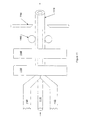
- FIG. 11 illustrates a manufacturing process of producing neutral displacement wicks in accordance with some embodiments of the invention.
- NDW neutral displacement wick
- a multi-component NDW wick 10 may comprise at least four (4) non-discrete (i.e., overlapping) portions: an immersion section 110 , an non-immersion section 120 , a displacement portion 130 , and a wicking portion 140 .
- the immersion section 110 and the non-immersion section 120 divide the wick laterally, while the displacement portion 130 and wicking portion 140 provide radial divisions in the wick 10 .
- the immersion section 110 is the section of the multi-component wick that is initially in the fluid.
- the non-immersion section 120 is the section of the multi-component wick that is initially outside of the fluid.
- the displacement portion 130 may run the entire length of the wick, or may be primarily disposed in the immersion section 110 .
- the displacement portion 130 may possess some wicking characteristics, its primary purpose is to initially displace a specified amount of fluid.
- the wicking portion 140 may also run the entire length of the wick, although it is also contemplated to have the majority of the wicking portion 140 in the non-immersion section 120 of the wick.
- the surface area of the wicking portion 140 in the non-immersion section 120 will determine the dissemination rate of the evaporated fluid.
- a NDW 20 may be configured in a cylindrical shape, and may comprise a displacement portion 210 and a wicking portion 220 .
- the displacement portion 210 is shown as being radially-internal to the wicking portion 220 . In this manner, the displacement portion 210 may not only be generally hidden, but the wicking portion 220 may be fully exposed to the ambient environment, thereby allowing for optimal evaporation, and thus, fragrance dissemination.
- a NDW 30 may again be comprised in a cylindrical shape and may comprise a first wicking portion 310 , and a second wicking portion 320 .
- the NDW 30 may also comprise an impervious membrane 340 and a void area 350 . It is contemplated that the void area 350 may be used similar to the displacement portion in FIGS. 1 and 2 to displace a desired amount of fluid.
- the first wicking portion 310 may be designed to wick a specific material (e.g., it may be hydrophilic) while the second wicking portion 320 may be designed to wick a different specific material (e.g., it may be oleophilic), providing for multiple scents emitting from the NDW 30 .
- the first and second wicking portions 310 , 320 may wick the same materials at different rates, or either the first or the second wicking portion 310 , 320 may have aromas embedded therein.
- a NDW 40 may be rectangular in cross-section, and may comprise a displacement portion 410 and a wicking portion 420 .
- a NDW 50 may comprise at least three (3) portions: a first wicking portion 510 , a second wicking portion 520 , and a displacement portion 530 .
- the NDW 50 may comprise a wicking portion and a displacement portion separated by an impervious membrane.
- cross sections may be a wicking core and a non-wicking sheath, or any other configurations that would be obvious to one skilled in the art.
- wicking portion of the NDW wick may be self-sustaining porous bonded fiber elements that are well known to be able to be engineered to wick a variety of liquids and act as air freshener wick materials.
- examples of such materials may include bonded bicomponent polyolefin sheath fibers, bonded bicomponent polyester sheath fibers, bonded bicomponent nylon sheath fibers and bonded pneumatic nylon and pneumatic cellulose acetate.
- porous, non-bonded, wicking fiber elements may be stiffened by adhesives or otherwise made structurally sound to enable consistent wicking behavior.
- Woven, knitted or non-woven fabrics may be used, as well as natural fibrous or non-fibrous products (such as cotton or wool).
- open cell foams may be used (as long as they are of sufficient surface energy to allow wetting and wicking of the target fluid).
- porous plastics such as self-sustaining porous sintered plastic elements, may be used.
- Various other materials that provide adequate wicking and evaporation will be readily apparent to one skilled in the art.
- the non-wicking portion may be any material as long as it is so configured so that the target fluid will substantially not penetrate this portion and thus be displaced by the non-wicking portion.
- the non-wicking portion of the NDW wick may be impervious, and may be a closed cell foam material, such as a rod-shaped chemically resistant polyethylene or polyurethane foam, a solid rod, such as a variety of plastic or elastomeric rods, or even rods of wood or metal.
- the non-wicking portion may also be bonded or non-bonded fiber structures, or natural product structures, with the surface energy being such that the material would not wet out or wick the target fluid, even under elevated pressure conditions that may be experienced in a container.
- the wicking portion may be tight up against the non-wicking displacement portion to prevent voids from forming. Unsealed voids are unwanted because upon filling with the fragrant liquid, the volume of the container may appear to be less.
- the wicking portion and the non-wicking displacement portion may be arranged so as to prevent unwanted delamination or separation of the two portions.
- the wicking portion and the non-wicking displacement portion may be combined into a single unit by interference fit, or may be adhered together. Such adherence may be the result of fibers of the wicking portion bonding to the non-wicking displacement portion, or may result from the use of adhesives applied to the components.
- the wick may be sized to achieve the following objectives:
- FIGS. 6-10 illustrate the proper sizing for a NDW where the immersion section displaces an amount of fluid approximately equal to the amount fluid wicked into the wicking portion of the non-immersion section (note that the fluid level remains the same throughout).
- FIGS. 6 and 7 illustrate the undesirable effect of initial liquid drop in a fluid reservoir when a standard, non-NDW wick is used. It is desirable to properly size or configure an NDW wick to prevent similar fluid drops.
- FIGS. 8-9 illustrate a properly sized NDW wick that displaces an equal amount of liquid as it initially absorbs, maintaining the initial fluid level at approximately the top of the bottle.
- FIG. 10 illustrates an improperly sized wick that displaces more fluid than it absorbs, resulting in fluid overflow upon insertion.
- the ratio of the volume of liquid displaced by the immersion section (including the displacement portion) to the volume of liquid initially wicked into the wicking portion in the non-immersion section must be designed for each particular application, and must take into account the volume of the container, the size of the NDW and the desired liquid height inside the container before and after the insertion of the NDW. Ratios may range from 0.2 to 4.0. When a particular fluid level prior to NDW insertion is desired to be maintained after NDW insertion, ratios may range from 0.95 to 1.05. Design considerations include, but are not limited to, the desired evaporation rate of the liquid, the surface tension of the liquid that is to be wicked, the density of the wicking portion, the overall dimensions of the wicking portion, and the overall dimensions of the container.
- NDW may also be made in many different ways, including bonded fiber processes of many types, non-woven wrapping technologies, textile technologies, and a variety of forming technologies. NDW may be produced by separately manufacturing the porous, wicking portion and the non-wicking portion, and combining the portions into a final unit. As noted above, this combination may utilize an interference fit, may be thermally bonded together as part of the forming process or may utilize additional adhesives.
- the wicking portion may be formed integral to the displacement portion.
- the wicking portion may be formed around and integral to, the displacement portion, or, in the case of FIG. 3 , around a sealed void that provides the desired displacement.
- the displacement portion 1110 may be already formed.
- the displacement portion 1110 may comprise any material that does not wick or wet out with the intended liquid.
- the displacement portion 1110 may be a solid, a closed cell foam such as a chemically resistant polyethylene or polyurethane foam.
- the geographic arrangement of the displacement portion 1110 is illustrated in FIG. 11 as being cylindrical, it may take any desired cross-section.
- the wicking portion 1120 may be formed from a fibrous sheet into a three dimensional, self-sustaining structure around the displacement portion 1110 . Sheets or webs of fibrous material 1120 may be fed around the displacement portion 1110 to wrap or encase it.
- the encased combination of the fibrous material 1120 and the displacement portion 1110 may be fed into a heated die 1130 .
- the die 1130 may be heated by any variety of means (e.g., steam, induction, convection, etc.) and may maintain a temperature above the softening temperature of the fibers of the wicking portion 1120 .
- the wicking portion 1120 is comprised of bicomponent fibers (e.g., sheath-core or side-by-side bicomponent fibers) the die 1130 may be maintained at a temperature above the softening temperature of the lowest softening (or melting) temperature component.
- the softening temperature of the sheath will be exceeded by the temperature of the die 1130 .
- the heat from the die 1130 may cause the fibers to bond to each other at various points of contact.
- the wicking portion may be formed into the desired three dimensional, self-sustaining, porous fiber structure.
- the inner dimensions of the die may form the combined wicking portion 1120 and displacement portion 1110 into a desired cross section.
- a cooling die 1140 may be used to quicken the cooling of the heated fibers. Additionally, the cooling die 1140 may provide additional shaping of the cross section of the final product.
- the NDW 1170 is formed. The combined NDW 1170 may be pulled through the process by element 1160 , and may be cut to desired length by element 1150 .
- FIG. 11 depicts an NDW 1170 in a cylindrical shape with a circular cross section of both the wicking portion and the displacement portion, it is anticipated that any desired cross section may be obtained.
- FIG. 11 illustrates a single method for the manufacture of a NDW. Multiple other manufacturing methods may be used to produce, either separately or integrally, the wicking portion and displacement portion of the NDW.
Abstract
Description
-
- 1. The proper surface area (as determined by the circumference of the wick, the amount of wick exposed in the non-immersion section, and the vapor pressure of the target fluid). A proper surface area may allow a vapor release rate appropriate to the application in question.
- 2. Appropriate volume of liquid wicked up into the wick by capillary action (determined by the cross sectional area of the wicking portion, plus the capillary draw and porosity of the porous element).
- 3. The amount of liquid displaced (determined by (2) above plus the displacement of the displacement portion).
- 4. A desired relationship between the immersion section and the non-immersion section. For example, in some circumstances, it may be desirable to maintain a fluid level at the same height once a wick is inserted. In this situation, the initial volume of the immersion section (comprising the volume of both the displacement portion and the fiber volume of the wicking portion) should be approximately equal to the initial volume of fluid wicked by the wicking portion located in the non-immersion section. In other circumstances, it may be desirable to cause the fluid level to rise or drop once a wick is inserted. In such circumstances, the volume of the immersion section may initially be more or less, respectively, than the volume of fluid initially wicked by the wicking portion in the non-immersion section.
Claims (20)
Priority Applications (2)
| Application Number | Priority Date | Filing Date | Title |
|---|---|---|---|
| US12/795,403 US8047453B2 (en) | 2006-06-22 | 2010-06-07 | Neutral displacement wick |
| US12/978,907 US20110108630A1 (en) | 2006-06-22 | 2010-12-27 | Bonded Fiber Wick |
Applications Claiming Priority (3)
| Application Number | Priority Date | Filing Date | Title |
|---|---|---|---|
| US81582206P | 2006-06-22 | 2006-06-22 | |
| US11/765,538 US7731102B2 (en) | 2006-06-22 | 2007-06-20 | Neutral displacement wick |
| US12/795,403 US8047453B2 (en) | 2006-06-22 | 2010-06-07 | Neutral displacement wick |
Related Parent Applications (1)
| Application Number | Title | Priority Date | Filing Date |
|---|---|---|---|
| US11/765,538 Continuation US7731102B2 (en) | 2006-06-22 | 2007-06-20 | Neutral displacement wick |
Related Child Applications (1)
| Application Number | Title | Priority Date | Filing Date |
|---|---|---|---|
| US12/978,907 Continuation US20110108630A1 (en) | 2006-06-22 | 2010-12-27 | Bonded Fiber Wick |
Publications (2)
| Publication Number | Publication Date |
|---|---|
| US20100243755A1 US20100243755A1 (en) | 2010-09-30 |
| US8047453B2 true US8047453B2 (en) | 2011-11-01 |
Family
ID=38834380
Family Applications (3)
| Application Number | Title | Priority Date | Filing Date |
|---|---|---|---|
| US11/765,538 Expired - Fee Related US7731102B2 (en) | 2006-06-22 | 2007-06-20 | Neutral displacement wick |
| US12/795,403 Expired - Fee Related US8047453B2 (en) | 2006-06-22 | 2010-06-07 | Neutral displacement wick |
| US12/978,907 Abandoned US20110108630A1 (en) | 2006-06-22 | 2010-12-27 | Bonded Fiber Wick |
Family Applications Before (1)
| Application Number | Title | Priority Date | Filing Date |
|---|---|---|---|
| US11/765,538 Expired - Fee Related US7731102B2 (en) | 2006-06-22 | 2007-06-20 | Neutral displacement wick |
Family Applications After (1)
| Application Number | Title | Priority Date | Filing Date |
|---|---|---|---|
| US12/978,907 Abandoned US20110108630A1 (en) | 2006-06-22 | 2010-12-27 | Bonded Fiber Wick |
Country Status (4)
| Country | Link |
|---|---|
| US (3) | US7731102B2 (en) |
| EP (1) | EP2038039B1 (en) |
| ES (1) | ES2376008T3 (en) |
| WO (1) | WO2007149966A2 (en) |
Families Citing this family (7)
| Publication number | Priority date | Publication date | Assignee | Title |
|---|---|---|---|---|
| US7731102B2 (en) * | 2006-06-22 | 2010-06-08 | Filtrona Richmond, Inc. | Neutral displacement wick |
| US20080251599A1 (en) * | 2007-04-11 | 2008-10-16 | Ward Bennett C | Vapor Emitting Device |
| US20100176210A1 (en) * | 2009-01-09 | 2010-07-15 | Porex Corporation | Hydrophilic Porous Wicks for Vaporizable Materials |
| US9649400B2 (en) | 2012-08-17 | 2017-05-16 | S.C. Johnson & Son, Inc. | Method and system for dispensing a composition |
| GB201407056D0 (en) * | 2014-04-22 | 2014-06-04 | Essentra Filter Products Dev Co Pte Ltd | Smoking article |
| US10377556B2 (en) | 2015-02-04 | 2019-08-13 | S.C. Johnson & Son, Inc. | Retaining apparatus |
| EP3562519A1 (en) * | 2016-12-29 | 2019-11-06 | Airparfum Timeless, S.L. | Perfume testers |
Citations (11)
| Publication number | Priority date | Publication date | Assignee | Title |
|---|---|---|---|---|
| US1129897A (en) | 1914-05-16 | 1915-03-02 | George B Owen Jr | Air-moistening device. |
| US2277377A (en) | 1939-04-04 | 1942-03-24 | Joshua B Warner | Absorbing agent |
| US4739928A (en) | 1985-10-15 | 1988-04-26 | The Drackett Company | Air freshener dispenser |
| US5863196A (en) | 1996-08-30 | 1999-01-26 | Fil-Tec | Fray-resistant wick and method of manufacturing same |
| US6250511B1 (en) | 1999-11-05 | 2001-06-26 | Albert R. Kelly | Recharge insert for cleaning, sanitizing or disinfectant fluid spray system |
| US20040041285A1 (en) | 2002-06-20 | 2004-03-04 | Jian Xiang | Multi-component flow regulator wicks and methods of making multi-component flow regulator wicks |
| US6786427B2 (en) * | 2002-12-19 | 2004-09-07 | S. C. Johnson & Son, Inc. | Liquid sealing arrangements for replaceable liquid reservoirs |
| US6899280B2 (en) | 2002-10-08 | 2005-05-31 | S. C. Johnson & Son, Inc. | Wick-based delivery system with wick having sections of varying porosities |
| WO2006004902A1 (en) | 2004-06-30 | 2006-01-12 | S. C. Johnson & Son, Inc. | Improved wick to reduce liquid flooding and control release rate |
| US7055764B1 (en) * | 2004-12-21 | 2006-06-06 | Zobele Espana, S.A. | Two-phase evaporator device |
| US7731102B2 (en) * | 2006-06-22 | 2010-06-08 | Filtrona Richmond, Inc. | Neutral displacement wick |
Family Cites Families (7)
| Publication number | Priority date | Publication date | Assignee | Title |
|---|---|---|---|---|
| ATE164493T1 (en) * | 1993-11-29 | 1998-04-15 | Courtaulds Fibres Holdings Ltd | CIGARETTE FILTERING |
| WO2002031413A2 (en) * | 2000-10-09 | 2002-04-18 | The Dial Corporation | Method and apparatus for fastening a fluid transport mechanism to a container |
| US7888275B2 (en) | 2005-01-21 | 2011-02-15 | Filtrona Porous Technologies Corp. | Porous composite materials comprising a plurality of bonded fiber component structures |
| US20020193030A1 (en) * | 2001-04-20 | 2002-12-19 | Li Yao | Functional fibers and fibrous materials |
| US7007863B2 (en) * | 2002-10-08 | 2006-03-07 | S.C. Johnson & Son, Inc. | Wick-based delivery system with wick made of different composite materials |
| US7524463B2 (en) * | 2006-02-03 | 2009-04-28 | S.C. Johnson & Son, Inc. | Heated volatile dispensing device with dye-based use-up indicator |
| US20100176210A1 (en) * | 2009-01-09 | 2010-07-15 | Porex Corporation | Hydrophilic Porous Wicks for Vaporizable Materials |
-
2007
- 2007-06-20 US US11/765,538 patent/US7731102B2/en not_active Expired - Fee Related
- 2007-06-21 ES ES07784504T patent/ES2376008T3/en active Active
- 2007-06-21 WO PCT/US2007/071756 patent/WO2007149966A2/en active Application Filing
- 2007-06-21 EP EP07784504A patent/EP2038039B1/en not_active Expired - Fee Related
-
2010
- 2010-06-07 US US12/795,403 patent/US8047453B2/en not_active Expired - Fee Related
- 2010-12-27 US US12/978,907 patent/US20110108630A1/en not_active Abandoned
Patent Citations (12)
| Publication number | Priority date | Publication date | Assignee | Title |
|---|---|---|---|---|
| US1129897A (en) | 1914-05-16 | 1915-03-02 | George B Owen Jr | Air-moistening device. |
| US2277377A (en) | 1939-04-04 | 1942-03-24 | Joshua B Warner | Absorbing agent |
| US4739928A (en) | 1985-10-15 | 1988-04-26 | The Drackett Company | Air freshener dispenser |
| US5863196A (en) | 1996-08-30 | 1999-01-26 | Fil-Tec | Fray-resistant wick and method of manufacturing same |
| US6250511B1 (en) | 1999-11-05 | 2001-06-26 | Albert R. Kelly | Recharge insert for cleaning, sanitizing or disinfectant fluid spray system |
| US20040041285A1 (en) | 2002-06-20 | 2004-03-04 | Jian Xiang | Multi-component flow regulator wicks and methods of making multi-component flow regulator wicks |
| US6899280B2 (en) | 2002-10-08 | 2005-05-31 | S. C. Johnson & Son, Inc. | Wick-based delivery system with wick having sections of varying porosities |
| US6786427B2 (en) * | 2002-12-19 | 2004-09-07 | S. C. Johnson & Son, Inc. | Liquid sealing arrangements for replaceable liquid reservoirs |
| WO2006004902A1 (en) | 2004-06-30 | 2006-01-12 | S. C. Johnson & Son, Inc. | Improved wick to reduce liquid flooding and control release rate |
| US20060011733A1 (en) | 2004-06-30 | 2006-01-19 | Varanasi Padma P | Wick to reduce liquid flooding and control release rate |
| US7055764B1 (en) * | 2004-12-21 | 2006-06-06 | Zobele Espana, S.A. | Two-phase evaporator device |
| US7731102B2 (en) * | 2006-06-22 | 2010-06-08 | Filtrona Richmond, Inc. | Neutral displacement wick |
Also Published As
| Publication number | Publication date |
|---|---|
| EP2038039A2 (en) | 2009-03-25 |
| WO2007149966A2 (en) | 2007-12-27 |
| US7731102B2 (en) | 2010-06-08 |
| EP2038039B1 (en) | 2011-12-07 |
| US20100243755A1 (en) | 2010-09-30 |
| ES2376008T3 (en) | 2012-03-08 |
| US20110108630A1 (en) | 2011-05-12 |
| US20070295831A1 (en) | 2007-12-27 |
| EP2038039A4 (en) | 2010-06-23 |
| WO2007149966A3 (en) | 2009-04-16 |
Similar Documents
| Publication | Publication Date | Title |
|---|---|---|
| US8047453B2 (en) | Neutral displacement wick | |
| US6708897B1 (en) | Unit for the transfer and distribution of a liquid and method of manufacturing the same | |
| US5124200A (en) | Fray resistant and absorbent liquid transfer wick | |
| US20090308947A1 (en) | Methods and apparatus for a low-cost vapor-dispersing device | |
| EP1765424B1 (en) | Volatile dispenser with oriented fibrous emanator | |
| US20080251599A1 (en) | Vapor Emitting Device | |
| MX2007000903A (en) | Vapor dispersing device and method. | |
| WO2010014996A2 (en) | Wicks for dispensers of vaporizable materials | |
| CN113490428A (en) | Tubular element comprising porous medium for use with an aerosol-generating article | |
| CN211631799U (en) | Aerosol bomb with gas-liquid channel | |
| CA2580434C (en) | Container of active substances | |
| US9056144B1 (en) | Non-clogging, non-dripping and spillage and leakage-proof air-scenting method and device | |
| JP2008523938A (en) | Two-phase evaporator | |
| US8517283B1 (en) | Non-clogging, non-dripping and spillage and leakage-proof air-scenting method and device | |
| US9114558B1 (en) | Method of making a non-clogging porous fibrous mass for air scenting | |
| US8464965B1 (en) | Non-dripping and spillage and leakage-proof air-scenting method and device | |
| US20160346420A1 (en) | Fragrance and chemical dispensers and methods for using the same | |
| EP2911505A1 (en) | Volatile material dispenser and dispensing screen therefor | |
| RU2811971C2 (en) | Aerosol-generating article, method of its manufacture and aerosol-generating device containing such product | |
| JP2011063914A (en) | Fiber molding, method for producing the same, writing utensil and liquid-feeding tool | |
| JP3153493U (en) | Suction volatilization member for liquid volatilizer | |
| EP3323434A1 (en) | Dispensing device having an anti-dripping system | |
| JP2002000157A (en) | Liquid absorbing wick | |
| JP2006306479A (en) | Aromatic container for artificial flower and its mounting structure | |
| JP2003144536A (en) | Volatile medicine gradually discharging member and air conditioner using it |
Legal Events
| Date | Code | Title | Description |
|---|---|---|---|
| AS | Assignment |
Owner name: FILTRONA POROUS TECHNOLOGIES CORP., VIRGINIA Free format text: ASSIGNMENT OF ASSIGNORS INTEREST;ASSIGNOR:FILTRONA RICHMOND, INC.;REEL/FRAME:025544/0202 Effective date: 20101210 |
|
| STCF | Information on status: patent grant |
Free format text: PATENTED CASE |
|
| AS | Assignment |
Owner name: ESSENTRA POROUS TECHNOLOGIES CORP., VIRGINIA Free format text: CHANGE OF NAME;ASSIGNOR:FILTRONA POROUS TECHNOLOGIES CORP.;REEL/FRAME:031409/0011 Effective date: 20131014 |
|
| FPAY | Fee payment |
Year of fee payment: 4 |
|
| AS | Assignment |
Owner name: GOLDMAN SACHS BANK USA, AS COLLATERAL AGENT, NEW J Free format text: SECURITY INTEREST;ASSIGNOR:POREX TECHNOLOGIES CORPORATION, F/K/A, ESSENTRA POROUS TECHNOLOGIES CORP.;REEL/FRAME:042461/0917 Effective date: 20170406 Owner name: POREX TECHNOLOGIES CORPORATION, VIRGINIA Free format text: CHANGE OF NAME;ASSIGNOR:ESSENTRA POROUS TECHNOLOGIES CORP.;REEL/FRAME:042528/0180 Effective date: 20170306 |
|
| AS | Assignment |
Owner name: GOLDMAN SACHS BANK USA, AS COLLATERAL AGENT, NEW JERSEY Free format text: SECURITY INTEREST;ASSIGNORS:AG INDUSTRIES LLC;AIR SYSTEM PRODUCTS LLC;CHEMCO MANUFACTURING CO., INC.;AND OTHERS;REEL/FRAME:045768/0001 Effective date: 20180329 Owner name: GOLDMAN SACHS BANK USA, AS COLLATERAL AGENT, NEW J Free format text: SECURITY INTEREST;ASSIGNORS:AG INDUSTRIES LLC;AIR SYSTEM PRODUCTS LLC;CHEMCO MANUFACTURING CO., INC.;AND OTHERS;REEL/FRAME:045768/0001 Effective date: 20180329 |
|
| AS | Assignment |
Owner name: POREX TECHNOLOGIES CORPORATION F/K/A ESSENTRA PORO Free format text: RELEASE BY SECURED PARTY;ASSIGNOR:GOLDMAN SACHS BANK USA, AS COLLATERAL AGENT;REEL/FRAME:045393/0092 Effective date: 20180329 |
|
| FEPP | Fee payment procedure |
Free format text: MAINTENANCE FEE REMINDER MAILED (ORIGINAL EVENT CODE: REM.); ENTITY STATUS OF PATENT OWNER: LARGE ENTITY |
|
| LAPS | Lapse for failure to pay maintenance fees |
Free format text: PATENT EXPIRED FOR FAILURE TO PAY MAINTENANCE FEES (ORIGINAL EVENT CODE: EXP.); ENTITY STATUS OF PATENT OWNER: LARGE ENTITY |
|
| STCH | Information on status: patent discontinuation |
Free format text: PATENT EXPIRED DUE TO NONPAYMENT OF MAINTENANCE FEES UNDER 37 CFR 1.362 |
|
| FP | Expired due to failure to pay maintenance fee |
Effective date: 20191101 |