US9155861B2 - Neural drug delivery system with fluidic threads - Google Patents
Neural drug delivery system with fluidic threads Download PDFInfo
- Publication number
- US9155861B2 US9155861B2 US13/236,973 US201113236973A US9155861B2 US 9155861 B2 US9155861 B2 US 9155861B2 US 201113236973 A US201113236973 A US 201113236973A US 9155861 B2 US9155861 B2 US 9155861B2
- Authority
- US
- United States
- Prior art keywords
- port
- fluid
- drug delivery
- fluid delivery
- delivery system
- Prior art date
- Legal status (The legal status is an assumption and is not a legal conclusion. Google has not performed a legal analysis and makes no representation as to the accuracy of the status listed.)
- Active, expires
Links
Images


Classifications
-
- A—HUMAN NECESSITIES
- A61—MEDICAL OR VETERINARY SCIENCE; HYGIENE
- A61M—DEVICES FOR INTRODUCING MEDIA INTO, OR ONTO, THE BODY; DEVICES FOR TRANSDUCING BODY MEDIA OR FOR TAKING MEDIA FROM THE BODY; DEVICES FOR PRODUCING OR ENDING SLEEP OR STUPOR
- A61M25/00—Catheters; Hollow probes
- A61M25/0067—Catheters; Hollow probes characterised by the distal end, e.g. tips
- A61M25/0068—Static characteristics of the catheter tip, e.g. shape, atraumatic tip, curved tip or tip structure
- A61M25/007—Side holes, e.g. their profiles or arrangements; Provisions to keep side holes unblocked
-
- A—HUMAN NECESSITIES
- A61—MEDICAL OR VETERINARY SCIENCE; HYGIENE
- A61M—DEVICES FOR INTRODUCING MEDIA INTO, OR ONTO, THE BODY; DEVICES FOR TRANSDUCING BODY MEDIA OR FOR TAKING MEDIA FROM THE BODY; DEVICES FOR PRODUCING OR ENDING SLEEP OR STUPOR
- A61M25/00—Catheters; Hollow probes
- A61M25/0043—Catheters; Hollow probes characterised by structural features
- A61M2025/0058—Catheters; Hollow probes characterised by structural features having an electroactive polymer material, e.g. for steering purposes, for control of flexibility, for locking, for opening or closing
-
- A—HUMAN NECESSITIES
- A61—MEDICAL OR VETERINARY SCIENCE; HYGIENE
- A61M—DEVICES FOR INTRODUCING MEDIA INTO, OR ONTO, THE BODY; DEVICES FOR TRANSDUCING BODY MEDIA OR FOR TAKING MEDIA FROM THE BODY; DEVICES FOR PRODUCING OR ENDING SLEEP OR STUPOR
- A61M2210/00—Anatomical parts of the body
- A61M2210/10—Trunk
- A61M2210/1003—Spinal column
Definitions
- This invention relates generally to the medical field, and more specifically to an improved neural drug delivery system in the oncology field.
- GBM glioblastoma multiforme
- the objective is to deliver the right therapeutic agent (e.g., conventional small molecule chemotherapy drug, large molecule biologic drug, nanoparticle, or perhaps even virus vector) to the correct brain region, at the most efficacious times and at the most efficacious dosage, all while not damaging normal brain tissue and maintaining patient safety and quality of life.
- the right therapeutic agent e.g., conventional small molecule chemotherapy drug, large molecule biologic drug, nanoparticle, or perhaps even virus vector
- This is a difficult, largely unsolved problem due to the critical intrinsic complexities of the tumor-brain system and interfacing with it, including complex and highly variable tumor morphology, composition, and mass transport, and complex technologies required for sophisticated implantable drug delivery devices.
- CED convection-enhanced delivery
- This invention provides such an improved neural drug delivery system.
- FIGS. 1A-1D and 2 are schematics of the neural drug delivery system of a preferred embodiment implanted in tissue;
- FIGS. 3A-3C are variations of the fluid delivery conduits in the neural drug delivery system of a preferred embodiment
- FIGS. 4A-4C are schematics of the relative conductive signal input, overall view, and detailed view, respectively, of the port gate in the closed mode in the neural drug delivery system of a preferred embodiment
- FIGS. 5A-5C are schematics of the relative conductive signal input, overall view, and detailed view, respectively, of the port gate in a gradient open mode in the neural drug delivery system of a preferred embodiment
- FIGS. 6A-6C are schematics of the relative conductive signal input, overall view, and detailed view, respectively, of the port gate in the open mode in the neural drug delivery system of a preferred embodiment
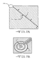
- FIGS. 7A and 7B are schematics of the interconnect network, ports, and sensor and electrode array of the neural drug delivery system of a preferred embodiment
- FIGS. 8A-8D are variations of the interconnect network of the neural drug delivery system of a preferred embodiment
- FIG. 9 is a table of example specifications of the neural drug delivery system of a preferred embodiment.
- FIGS. 10A-10E are schematics of fabrication of a port gate in the neural drug delivery system of a preferred embodiment.
- the neural drug delivery system 100 of a preferred embodiment includes: a plurality of elongated fluid delivery conduits 110 , or “fluidic threads”, that are implantable into tissue and configured to transport fluid 106 in which each of at least a portion of the conduits defines an array of fluid delivery ports 116 through which fluid is selectively released to the tissue; a plurality of port gates 120 each including a thin-film mesh structure 122 that is coupled to a corresponding fluid delivery port 116 and at least partially coated with an electroactive polymer 124 , in which each port gate is selectively operable between a closed mode and an open mode in response of the electroactive polymer 124 to a conductive signal; a voltage source 140 that provides the conductive signal to the plurality of port gates 120 ; and an interconnect network 150 , coupled to the voltage source and to the plurality of port gates, that carries the conductive signal from the voltage source to each of the plurality of port gates.
- the plurality of port gates 120 preferably includes a first portion of port gates that is operable between the closed and open modes independently of a second portion of port gates. At least a portion of the fluidic threads may further include an array of electrode sites suitable for recording, stimulation, and/or impedance measurements, such as for enabling feedback control of drug delivery and relative localization of drug to the targeted tissue, or other applications.
- the neural drug delivery system 100 with fluidic threads preferably provides highly adjustable pressure-driven drug infusion at selectable discrete locations, particularly for the treatment of cancer.
- a coarse level of drug coverage control is preferably achieved by determining the number of fluidic threads implanted in the tissue and their position in and around a tumor.
- An additional, finer level of drug coverage control is preferably achieved by adjusting infusion pressure amplitude and waveform, and/or by selectively operating a desired portion of port gates 120 between their closed and open modes. Further control of drug delivery to tissue may be achieved by selectively operating the port gates 120 in one or more gradient open modes, that allow transfer of the fluid through its corresponding port at any one of a range of flow rates (i.e., gates are partway open).
- the fine control of drug delivery is useful, for example, to optimize drug delivery and treatment to unique terrain of a particular tumor while avoiding drug delivery to non-cancerous tissue and reducing adverse effects on healthy tissue.
- the neural drug delivery system may include stimulation electrode sites, and additionally and/or alternatively be used for electrochemotherapy, which uses electric fields to enhance the cytotoxicity level of standard chemotherapeutic treatment of tumors. Applying an electric field to tissue increases cell permeability in a process called electroporation, thereby increasing the efficacy of chemotherapy treatment.
- the neural drug delivery system 100 enables a means for precise, scalable, and programmable direct delivery of chemotherapeutic agents to brain tumors over time.
- the neural drug delivery system preferably supports clinical therapy for brain tumors, but may be used for any suitable type of fluid delivery in other neural tissue, or any suitable body tissue or other substance.
- the actuation system of the port gates may be used in other applications that employ gating of a small fluidic port, in other drug delivery devices (e.g., any suitable type of catheter) or other suitable applications that require precise microfluidic flow control.
- the neural drug delivery system is innovative in terms of, for example, (1) achieving individually addressable gradient flow control across an array of fluid ports 116 to improve controlled drug delivery; (2) integrated sensing of relative location and local tissue properties using neural recording and measuring local tissue impedance; (3) use of clinical-grade materials and components to increase clinical and commercial feasibility.
- the plurality of fluid delivery conduits 110 function to transport a fluid such as chemotherapy drug treatment or any suitable fluid within the system.
- a fluid such as chemotherapy drug treatment or any suitable fluid within the system.
- distal portions of the plurality of fluidic threads 110 are preferably implanted into a particular targeted location such as in a brain tumor or any suitable tissue.
- the fluidic threads are preferably flexible, but a fluidic thread may include at least a portion that has any suitable amount of rigidity.
- Proximal portions of the fluidic threads are preferably externalized outside the cranium and connected to an external controllable infusion pump, drug reservoir, and/or control instrumentation or other device.
- the proximal portions of the fluidic threads are preferably clustered, but alternatively each fluidic thread may be individually connected to a corresponding infusion pump, drug reservoir, and/or control instrumentation or other device. All of the fluidic threads may transport the same fluid, or different fluidic threads may be coupled to different devices and transport different fluids.
- the fluidic threads 110 each preferably includes at least one lumen 112 such that the .fluidic threads transport the fluid with the lumen
- a fluidic thread may include multiple lumens 112 that transport multiple fluids.
- a fluidic thread may include two lumens each transporting a different fluid, where a first lumen carrying a first fluid is in fluidic communication with a first portion of the ports 116 and a second lumen carrying a second fluid is in fluidic communication with a second portion of the ports 116 .
- the lumen 112 is preferably arcuate such that it extends at least partially circumferentially along a side wall of the fluidic thread, but may be lune-shaped, elliptical, circular, or any suitable shape.
- the lumen 112 may be pressurized by an infusion pump 170 or other source to help facilitate fluid flow through a port 116 when its corresponding port gate 120 is in the open mode.
- the internal pressure of the fluidic thread may be set or modulated between approximately 2-15 psi, but may alternatively be set or modulated to any suitable pressure level.
- the fluidic threads may additionally and/or alternatively include receptacles that are pre-filled with the fluid prior to implantation of the fluidic threads, with each receptacle being coupled to a corresponding port gate.
- some or all of the fluidic threads may be impregnated with a drug or another substance that is released into and absorbed by tissue over time. Any one fluidic thread may also have a combination of one or more lumens that transport a fluid from an external device, one or more fluid receptacles, and/or be impregnated with a time-released substance.
- the fluidic threads may be solid, and the receptacles and/or impregnations may or may not be coupled to a corresponding port that regulates transfer of the fluid to the target tissue.
- the fluidic threads 110 may include a passageway that receives a removable, steerable stylet 114 .
- the fluidic threads are preferably positioned in targeted tissue by inserting the stylet 114 into a lumen or other passageway 112 ′ of a fluidic thread, manipulating the stylet 114 to control the position of the fluidic thread, and removing the stylet 114 from the passageway of the fluidic thread.
- the stylet 114 may be flexible and/or jointed, and steerable through manual manipulation, cables, or any suitable control system.
- the stylet may couple to the fluidic thread in any suitable manner, and/or the stylet may be resorabable into the body after the fluidic thread is positioned.
- the fluidic threads may be strategically positioned and manipulated to avoid nontargeted tissue as much as possible, such as to reduce unnecessary tissue damage.
- At least a portion of the fluidic threads 110 preferably defines an array of fluid.
- delivery ports 116 through which transfer of the fluid from the fluidic thread to the target tissue is facilitated.
- the fluid delivery ports 116 are preferably distributed along the length of the fluidic thread, and may be additionally and/or alternatively located on a tip of the fluidic thread.
- the array of ports may be distributed longitudinally along and/or circumferentially around the fluidic thread.
- the array of ports may be arranged in a regular pattern (e.g., rectangular or triangular) or in an irregular pattern.
- the ports are preferably elliptical (including circular), but may be rectangular, square, or any suitable shape.
- each fluidic thread 110 includes eight fluid delivery ports, but may alternatively include any suitable number of ports.
- the number and size of the ports may vary depending on the application (e.g., type of surrounding tissue) or the type of fluid (e.g., viscosity).
- the fluidic threads 110 may include an array of sensors and/or electrode sites 160 along their length or tip.
- the array of sensors and/or electrode sites (e.g. recording or stimulation electrode sites) is preferably arranged near one or more fluid delivery ports 116 .
- the sensors and/or electrode sites 160 may be annular structures positioned around the perimeter of a fluid delivery port, and/or integrated with the fluid delivery port to produce a multimodal, multichannel array capable of simultaneous drug delivery and recording, stimulation, and/or impedance setting.
- the sensors and/or electrode sites may be any suitable shape.
- the sensors and/or electrode sites may alternatively be separate structures independent of the ports and/or fluidic threads.
- the array of sensors and/or electrode sites preferably facilitate local neural recording and/or tissue impedance sensing that enable feedback control of fluid delivery and relative localization.
- stimulation electrode sites may be used to apply a high voltage electric field as part of electrochemotherapy treatment.
- the fluidic threads of the neural drug delivery system may include stimulation electrodes that can be used to apply an electric field to target tissue that is deeper and less accessible, where the electric field is highly customizable and adjustable based on the tissue environment.
- each fluidic thread 110 includes eight electrode sites, but may alternatively include any suitable number of sensors or electrode sites.
- each port gate 120 of the neural delivery system function as controllable valves that provide control over when and where the fluid is administered to neighboring tissue, by selectively regulating the transfer of the fluid through some or all of the ports.
- each port gate is preferably coupled to a corresponding port, and is selectively operable between a closed mode 126 and an open mode 128 and in some embodiments, one or more gradient open modes 127 .
- the closed mode 126 the port gate prevents transfer of the fluid through its corresponding port to the surrounding tissue.
- the open mode 128 the port gates 120 allow transfer of the fluid through its corresponding port to the surrounding tissue.
- the port gates may further operate in gradient open modes 127 that allow any of a range of flow rates of fluid through the port.
- the gradient open modes are preferably provided by opening the port gate in partially open (or partially closed) configurations.
- some or all of the fluid delivery ports 116 may be “active ” or “inactive” based on the activity of their corresponding port gates 120 .
- An “active” port 116 a may be considered to be a port whose corresponding port gate 120 a is operated in the open mode at least some of the time.
- an “inactive” port. 116 i may be considered to be a port whose corresponding port gate 120 i is never operated in the open mode, and is always in the closed mode As shown in FIG.
- the ports on the first portion of the fluidic threads may be active ports 116 a since it is desirable to have fluid administered to target issue 102 at least some of the time, while the ports on the second portion of the fluidic threads may be inactive ports 116 i since it is desirable to avoid adverse effects of the fluid administered. to nontargeted tissue 104 .
- each port gate preferably includes a mesh structure 122 coupled to a corresponding port and an electroactive polymer coating 124 on the mesh structure that is manipulated with a conductive signal to induce the closed and open modes of the port gate.
- the mesh structure 122 is preferably a microfabricated thin-film metal mesh, and more preferably a gold mesh, although the mesh may alternatively include any suitable material.
- the mesh dimensions, including crossbar dimensions, mesh size, and number of gaps per mesh structure, may depend on the application and properties of the electroactive polymer.
- each mesh structure has between 150 and 600 gaps or mesh holes 123 . Dimensions and quantities may be chosen, for example, to show a reproducible 35% increase in thickness in the closed mode compared to the open mode.
- the mesh structure may have any suitable specifications, including but not limited to those shown in FIG. 9 of exemplary embodiments.
- the electroactive polymer coating 124 on the mesh structure 122 is preferably a conjugated polymer that undergoes volume expansion or contraction when its oxidation or doping level is changed, thereby occluding or opening the mesh structure and inducing the closed or open modes, respectively.
- the doping level is preferably modulated by applying varying levels of conductive signal (e.g. voltage).
- the polymer coating is a material that is stable in an expanded (mesh-occluding) state, so that the port gate is in its closed mode by default, without requiring power to maintain the port gate in the closed mode.
- the coating 124 is an anion-transporting variation of polypyrrole (PPy).
- PPy polypyrrole
- An anion-transporting variation of PPy may be developed by electropolymerizing the PPy in the presence of small anions, ClO 4 , BF 4 , or PF 6 , or any suitable anion, as one ordinarily skilled in the art will know.
- the PPy coating 124 is stable in its oxidized and expanded state, meaning that a voltage must be actively applied to the PPy to retain the reduced and contracted state (this is due to oxygen doping and the polymer's electrochemical redox peak positions). Therefore, in this embodiment, as shown in FIG. 4 , the port gates 120 preferably operate in the closed mode by default (e.g.
- a voltage is preferably applied to the PPy coating 124 to cause the coating 124 to become reduced and contracted, thereby opening the mesh structure and allowing fluid transfer through the port. As shown in FIG. 6 , to induce the open mode 128 of the port gates 120 , a voltage is preferably applied to the PPy coating 124 to cause the coating 124 to become reduced and contracted, thereby opening the mesh structure and allowing fluid transfer through the port. As shown in FIG. 6
- one of a range of voltages is preferably applied to the PPy coating 124 to cause the coating 124 to reduce and contract by a particular discrete amount dependent on the applied voltage amount, thereby partially opening the mesh structure by an amount corresponding to the applied voltage amount.
- the port gates may be bimodal and operate between a closed mode 126 and solely one open mode; in other embodiments, the port gates may operate among a closed mode 126 and any suitable number of gradient open modes 127 .
- the anion-transporting PPy coating 124 may be one of three varieties of PPy: (1) PPy(Cl) gels, (2) PPy(ClO 4 ) gels reaching approximately 43% strain, (3) the PPy(CF 3 SO 3 ) gels reaching approximately 19% strain, and (4) the PPy(PF 6 ) reaching approximately 15% strain, or any variation reaching any suitable strain.
- the polymer properties of the coating on the port gates 120 may be tailored by adjusting the polymerization temperature, electrolyte concentration, and applied potential, among other parameters.
- one possible set of requirements for the port gates is that they exhibit leakage less than 1 nanoliter/minute in the closed mode, allow fluid flow of approximately 0.5 to 10 microliters/minute in the open mode (at least partially depending on applied fluidic pressure within the fluidic thread), and remain stable in physiological conditions (e.g., 37° C.).
- the polymer coating 124 may alternatively be a cation-transporting type of PPy such as PPy(DBS), or any suitable kind of electroactive polymer that enables selective volume expansion or contraction to induce closed and open modes of the port gates. All the port gates preferably have the same kind of coating applied in an identical manner, but may alternatively have different coatings.
- the voltage source 140 of the neural drug delivery system functions to provide a conductive signal that actuates the port gates 120 between the closed, open, and/or gradient open modes.
- the neural drug delivery system may include one voltage source, or multiple voltage sources.
- the voltage source 140 may be a battery, but may be any suitable kind of power source.
- the voltage source may be modulated to provide discrete levels of a conductive signal (e.g. 0.25 V, 0.5 V, 10 V), or may be modulated to provide any level of conductive signal along a continuous range (e.g., between 0.0 V and 2.0 V).
- the voltage source is preferably configured to be located external to the body when the fluidic threads 110 are implanted in tissue, but may additionally and/or alternatively be configured to be located within the body when the fluidic threads are implanted in tissue.
- the interconnect network 150 of the neural drug delivery system functions to carry conductive signals to and from the port gates 120 .
- the interconnect network 150 may additionally function to carry conductive signals to and from the array of sensors and/or electrodes, although the neural drug delivery system may include multiple interconnect networks, each for carrying different kinds of signals.
- the interconnect network 150 is preferably a thin-film network that includes interconnect leads (such as a flexible ribbon cable) arranged along the fluidic threads and a bond pad region 156 preferably located on a proximal portion of the interconnect network, more preferably external to the cranium. As shown in FIGS.
- the interconnect network 150 preferably includes a central spine 152 that carries interconnect leads along a fluidic thread, between the port gates 120 and/or electrode sites and the bond pad region.
- the central spine 152 may extend axially along the fluidic thread, but may travel along the fluidic thread in a curved or any suitable manner.
- the interconnect network preferably includes branches 154 that extend from the central spine 152 to one or more respective port gates 120 , and these branches 154 may include one branching stage ( FIGS. 7 and 8A ) or multiple branching stages ( FIG. 8B ).
- the network may also include a spine and/or branches that wrap circumferentially around the fluidic thread, including helically ( FIG. 8C ).
- the ports and port gates are coupled to the branches on the network, preferably on the termination of the branch as in FIG. 8A , but alternatively and/or additionally on any length along a branch as in FIG. 8D .
- the network may have any suitable configuration that distributes the port and port gates for fluid transfer.
- different portions of the port gates 120 are preferably operable independently of one another.
- a first portion of port gates may be actuated between the closed mode 126 and open mode 128 independently of a second portion of port gates.
- actuation of the first portion of port gates into the open mode does not necessarily result in actuation of the second portion of port gates into the open mode.
- some of the port gates may be functionally grouped (e.g. multiple port gates along a single interconnect network branch) to have coupled actuation between the closed and open modes.
- the neural drug delivery system preferably further includes one or more connector assemblies 130 that couples the fluidic thread 110 to a fluidic source 170 and/or the voltage source 140 , and/or to additional electronic subsystems.
- the additional electronic subsystems may include a printed circuit board (PCB) and connector pins that may be coupled to a control system, or may include a multiplexer and/or other suitable control instrumentation or electrical components for communicating with a control system.
- the system may include multiple connector assemblies, each coupled to a respective fluidic thread, or may include fewer connector assemblies than fluidic threads such that at least a portion of the connector assemblies couple to multiple fluidic threads.
- Some embodiments of the neural drug delivery system may include internal gates located within the fluidic threads 110 that further regulate flow of drugs or other fluid within the fluidic threads.
- Such internal gates may be identical and operate similarly to the port gates, and/or may include any suitable kind of valve.
- such internal gates may be useful in a fluidic thread having ports located along multiple branching stages, such that internal gates enable fluid delivery within the conduit 110 to only a portion of the ports.
- the neural drug delivery system may include features to reduce or eliminate reflux (backflow of the fluid into the fluidic threads), such as a step design cannula that is known by one ordinarily skilled in the art, or any suitable reflux-reducing feature.
- the components of the neural drug delivery system 100 are preferably procured and/or fabricated separately before assembly. Particular specifications of the various components may be similar to those shown in FIG. 9 of exemplary embodiments, but the components may have any suitable specifications such as material type, compositions, and dimensions.
- the fluidic thread 110 is an extruded tube, such as an extruded tube made from a thermoplastic copolymer (e.g. CarboSil®, DSM PTG), or any material that provides suitable flexibility, biocompatibility, biostability, processability, and robustness or other suitable material.
- a thermoplastic copolymer e.g. CarboSil®, DSM PTG
- the extruded tubing has a diameter of approximately 600 ⁇ m and a length that allows for an insertable length (configured to be implanted in tissue) of at least 3 cm (more preferably 6 cm), but the tubing may have any suitable length and diameter.
- the extruded tube may be a polyimide tube, such as a polyimide tube having an outer diameter of 1 millimeter, or any suitable size. The tube is preferably prepared for assembly by sealing the distal end with epoxy and drilling one or more ports 116 in the side walls of the tube, but may be prepared in any suitable manner.
- fabrication of the port gate 120 begins with a silicon wafer as a substrate for the mesh structure. After a sacrificial layer has been deposited, approximately 3-5 ⁇ m of polyimide will be spun on, patterned, and etched ( FIG. 10A ). A Cr/Au seed layer will be deposited ( FIG. 10B ) and the Au mesh and interconnect layer will be electroplated to the chosen thickness through a patterned photoresist mask ( FIG. 10C ). After the photoresist is stripped and the Au seed layer is removed in the mesh structure gap areas, polyimide will be spun on (to a thickness of approximately 3-5 ⁇ m) and patterned to insulate the Au interconnect ( FIG. 10D ).
- the mesh structures 122 are then released by dissolving the sacrificial layer ( FIG. 10E ).
- the process requires at least 3 masks/lithography steps, and may incorporate any additional and/or alternative suitable materials in any step.
- suitable materials may be used for the substrate and/or dielectric layers, including but not limited to parylene and various combinations of polyimide and silicon carbide (SiC).
- the PPy or other polymer coating 124 on the mesh structure may be electrochemically deposited on the Au mesh using a potentiostat, and a variety of coating thicknesses may be used based on their ability to close the mesh gaps in the mesh structure.
- the coating may additionally and/or alternatively be deposited in any suitable process, such as spin coating directly from the coating solution, spin coating from a precursor or monomer, chemical vapor deposition (CVD), or electrochemical deposition. For example, assuming a reversible 35% strain, PPy may be deposited to a thickness equivalent to 2 ⁇ 3 of half the gap width. The coating thickness depends linearly on the polymerization time, and can be readily adjusted as needed.
- the mesh structure may be designed with metal coating the entire 3D structure that allows the polymer coating to wrap completely around. This design may greatly reduce or eliminate the risk of PPy delamination during actuation in physiological fluid.
- the electroplating process in fabrication of the mesh structure may leave an inherently rough surface that may reduce or eliminate delamination issues, and the surface and be further roughed using surface modification techniques such as plasma treatment, to further enhance adhesion of the polymer coating to the mesh structure.
- the interconnect network 150 is preferably a thin-film structure that is fabricated in the same process as the port gate such that the interconnect network is integrally joined to the port gate.
- the interconnect network may be separately fabricated using a similar manufacturing process, and then joined to the port gate.
- the interconnect network and the plurality of port gates may be separate until they are attached to the fluidic thread, essentially becoming joined only during assembly of the overall neural drug delivery system.
- Sensors or electrode sites 160 may be created using any suitable manufacturing process, such as those described in U.S. Patent Application 2006/0282014 entitled “Flexible polymer microelectrodes with delivery capability and methods for making same” or U.S. Patent Application 2008/0208283 entitled “Neural interface system”, which are both incorporated in their entirety by this reference, or any other suitable electrode site manufacturing process.
- the sensors or electrode sites 160 may include gold, platinum, PPy, or any suitable material.
- the electrode sites 160 may be patterned directly onto the fluidic thread, onto the interconnect network, and/or separately and later coupled to the fluidic thread and/or interconnect network.
- the bond pads of the interconnect network are preferably ultrasonically bonded to the connector assembly.
- the rest of the interconnect network, including the branches, and port gates are preferably attached to the fluidic threads 110 with epoxy or other adhesive, preferably a medical-grade, UV-curable epoxy that is capable of being cured through polyimide, such as Dymax 204-CTH.
- the interconnect network 150 and port gates 120 it is important to accurately place and adhere the interconnect network 150 and port gates 120 to the fluidic thread.
- An assembly jig may be used to handle and align the components (e.g. align the sensor or electrode sites, port gates, and/or the ports of the fluidic thread) during this step.
- a variety of epoxies with different viscosities may also be used to adhere the interconnect network, port gates and/or sensor or electrode array to the fluidic thread.
- the mesh structure of the port gates should be well adhered to the fluidic threads and clear of epoxy.
Abstract
Description
Claims (27)
Priority Applications (1)
| Application Number | Priority Date | Filing Date | Title |
|---|---|---|---|
| US13/236,973 US9155861B2 (en) | 2010-09-20 | 2011-09-20 | Neural drug delivery system with fluidic threads |
Applications Claiming Priority (2)
| Application Number | Priority Date | Filing Date | Title |
|---|---|---|---|
| US38446610P | 2010-09-20 | 2010-09-20 | |
| US13/236,973 US9155861B2 (en) | 2010-09-20 | 2011-09-20 | Neural drug delivery system with fluidic threads |
Publications (2)
| Publication Number | Publication Date |
|---|---|
| US20120078188A1 US20120078188A1 (en) | 2012-03-29 |
| US9155861B2 true US9155861B2 (en) | 2015-10-13 |
Family
ID=45871354
Family Applications (1)
| Application Number | Title | Priority Date | Filing Date |
|---|---|---|---|
| US13/236,973 Active 2034-05-18 US9155861B2 (en) | 2010-09-20 | 2011-09-20 | Neural drug delivery system with fluidic threads |
Country Status (1)
| Country | Link |
|---|---|
| US (1) | US9155861B2 (en) |
Cited By (3)
| Publication number | Priority date | Publication date | Assignee | Title |
|---|---|---|---|---|
| CN110072623A (en) * | 2016-12-13 | 2019-07-30 | 皇家飞利浦有限公司 | Flow control apparatus |
| US10933218B2 (en) | 2013-07-30 | 2021-03-02 | Massachusetts Institute Of Technology | Systems and methods for delivering chemical and electrical stimulation across one or more neural circuits |
| US11433423B2 (en) | 2017-12-15 | 2022-09-06 | Board Of Regents, The University Of Texas System | Electroactive materials comprising a piezoelectric polymer and a conducting polymer |
Families Citing this family (7)
| Publication number | Priority date | Publication date | Assignee | Title |
|---|---|---|---|---|
| US11273287B2 (en) * | 2013-03-08 | 2022-03-15 | Endobar Solutions Llc | Selectively delivering particles into the distal portion of the left gastric artery |
| CA2936830C (en) * | 2014-01-17 | 2022-06-07 | Endobar Solutions, LLC | Selectively delivering particles into the distal portion of the left gastric artery |
| WO2015195625A1 (en) * | 2014-06-17 | 2015-12-23 | Endobar Solutions Llc | Selectively delivering particles into the distal portion of the left gastric artery |
| FR3031041B1 (en) * | 2014-12-26 | 2020-11-06 | Commissariat Energie Atomique | IMPLANTABLE OPTICAL BRAIN STIMULATION DEVICE INCLUDING A MULTI-CHANNEL CATHETER |
| CN108671370A (en) * | 2018-06-20 | 2018-10-19 | 南京林业大学 | The insulin closed loop controlled release mechanisms of biological fuel cell driving |
| CN112494741B (en) * | 2020-11-30 | 2021-09-24 | 牡丹江医学院 | Visual intestinal lavage device for children |
| DE102022115568A1 (en) | 2022-06-22 | 2023-12-28 | Rheinisch-Westfälische Technische Hochschule Aachen, Körperschaft des öffentlichen Rechts | Catheter for local treatment of tumor tissue in intravascular and intraluminal spaces |
Citations (111)
| Publication number | Priority date | Publication date | Assignee | Title |
|---|---|---|---|---|
| US3847687A (en) | 1972-11-15 | 1974-11-12 | Motorola Inc | Methods of forming self aligned transistor structure having polycrystalline contacts |
| US3921916A (en) | 1974-12-31 | 1975-11-25 | Ibm | Nozzles formed in monocrystalline silicon |
| US4141365A (en) | 1977-02-24 | 1979-02-27 | The Johns Hopkins University | Epidural lead electrode and insertion needle |
| US4166469A (en) | 1977-12-13 | 1979-09-04 | Littleford Philip O | Apparatus and method for inserting an electrode |
| US4306562A (en) | 1978-12-01 | 1981-12-22 | Cook, Inc. | Tear apart cannula |
| US4455192A (en) | 1981-05-07 | 1984-06-19 | Fuji Xerox Company, Ltd. | Formation of a multi-nozzle ink jet |
| US4461304A (en) | 1979-11-05 | 1984-07-24 | Massachusetts Institute Of Technology | Microelectrode and assembly for parallel recording of neurol groups |
| US4465482A (en) | 1979-03-07 | 1984-08-14 | Gerhard Hug Gmbh | Suction drainage tube |
| US4762135A (en) | 1985-08-30 | 1988-08-09 | Puije P D V D | Cochlea implant |
| US4886065A (en) | 1988-08-08 | 1989-12-12 | California Institute Of Technology | In vivo electrode implanting system |
| US4904237A (en) | 1988-05-16 | 1990-02-27 | Janese Woodrow W | Apparatus for the exchange of cerebrospinal fluid and a method of treating brain and spinal cord injuries |
| US5108819A (en) | 1990-02-14 | 1992-04-28 | Eli Lilly And Company | Thin film electrical component |
| US5180376A (en) | 1990-05-01 | 1993-01-19 | Cathco, Inc. | Non-buckling thin-walled sheath for the percutaneous insertion of intraluminal catheters |
| US5207709A (en) | 1991-11-13 | 1993-05-04 | Picha George J | Implant with textured surface |
| US5215088A (en) | 1989-11-07 | 1993-06-01 | The University Of Utah | Three-dimensional electrode device |
| US5308442A (en) | 1993-01-25 | 1994-05-03 | Hewlett-Packard Company | Anisotropically etched ink fill slots in silicon |
| US5322064A (en) | 1991-02-15 | 1994-06-21 | Lundquist Ingemar H | Torquable catheter and method |
| US5385635A (en) | 1993-11-01 | 1995-01-31 | Xerox Corporation | Process for fabricating silicon channel structures with variable cross-sectional areas |
| US5390671A (en) | 1994-03-15 | 1995-02-21 | Minimed Inc. | Transcutaneous sensor insertion set |
| US5409469A (en) | 1993-11-04 | 1995-04-25 | Medtronic, Inc. | Introducer system having kink resistant splittable sheath |
| US5496360A (en) | 1994-04-12 | 1996-03-05 | Ventritex, Inc. | Implantable cardiac electrode with rate controlled drug delivery |
| US5515848A (en) | 1991-10-22 | 1996-05-14 | Pi Medical Corporation | Implantable microelectrode |
| US5573520A (en) | 1991-09-05 | 1996-11-12 | Mayo Foundation For Medical Education And Research | Flexible tubular device for use in medical applications |
| US5585827A (en) | 1993-10-29 | 1996-12-17 | Sony Corporation | Printer head |
| US5588597A (en) | 1993-09-03 | 1996-12-31 | Microparts Gmbh | Nozzle plate for a liquid jet print head |
| US5720099A (en) | 1996-01-31 | 1998-02-24 | Cochlear Limited | Thin film fabrication technique for implantable electrodes |
| US5744958A (en) | 1995-11-07 | 1998-04-28 | Iti Medical Technologies, Inc. | Instrument having ultra-thin conductive coating and method for magnetic resonance imaging of such instrument |
| US5800535A (en) | 1994-02-09 | 1998-09-01 | The University Of Iowa Research Foundation | Wireless prosthetic electrode for the brain |
| US5843150A (en) | 1997-10-08 | 1998-12-01 | Medtronic, Inc. | System and method for providing electrical and/or fluid treatment within a patient's brain |
| US5927277A (en) | 1995-04-28 | 1999-07-27 | Medtronic, Inc. | Method and apparatus for securing probes within a burr hole |
| US5938694A (en) | 1993-11-10 | 1999-08-17 | Medtronic Cardiorhythm | Electrode array catheter |
| US5975085A (en) | 1997-05-01 | 1999-11-02 | Medtronic, Inc. | Method of treating schizophrenia by brain stimulation and drug infusion |
| US5989445A (en) | 1995-06-09 | 1999-11-23 | The Regents Of The University Of Michigan | Microchannel system for fluid delivery |
| US6006124A (en) | 1998-05-01 | 1999-12-21 | Neuropace, Inc. | Means and method for the placement of brain electrodes |
| US6016449A (en) | 1997-10-27 | 2000-01-18 | Neuropace, Inc. | System for treatment of neurological disorders |
| US6044304A (en) | 1998-04-29 | 2000-03-28 | Medtronic, Inc. | Burr ring with integral lead/catheter fixation device |
| US6132456A (en) | 1998-03-10 | 2000-10-17 | Medtronic, Inc. | Arrangement for implanting an endocardial cardiac lead |
| US6181569B1 (en) | 1999-06-07 | 2001-01-30 | Kishore K. Chakravorty | Low cost chip size package and method of fabricating the same |
| WO2001012115A1 (en) | 1999-08-18 | 2001-02-22 | Epic Biosonics Inc. | Modiolar hugging electrode array |
| US6205361B1 (en) | 1998-02-10 | 2001-03-20 | Advanced Bionics Corporation | Implantable expandable multicontact electrodes |
| US6228111B1 (en) | 1995-09-27 | 2001-05-08 | Bionx Implants Oy | Biodegradable implant manufactured of polymer-based material and a method for manufacturing the same |
| US6324433B1 (en) | 2000-01-20 | 2001-11-27 | Electrocare Technologies, Llc | Electrode-lead coupling skull mounted port assembly |
| US6325797B1 (en) | 1999-04-05 | 2001-12-04 | Medtronic, Inc. | Ablation catheter and method for isolating a pulmonary vein |
| US20010049499A1 (en) | 1999-12-30 | 2001-12-06 | Lui Chun Kee | Splittable medical valve |
| US20020052610A1 (en) | 2000-04-07 | 2002-05-02 | Skakoon James G. | Deep organ access device and method |
| WO2002036002A1 (en) | 2000-11-01 | 2002-05-10 | 3M Innovative Properties Company | Electrical sensing and/or signal application device |
| WO2002041666A1 (en) | 2000-11-14 | 2002-05-23 | Cochlear Limited | Apparatus for delivery of pharmaceuticals to the cochlea |
| US6430443B1 (en) | 2000-03-21 | 2002-08-06 | Manuel L. Karell | Method and apparatus for treating auditory hallucinations |
| US20020111601A1 (en) * | 2001-02-12 | 2002-08-15 | Medtronic, Inc | Drug delivery device |
| US20020183817A1 (en) | 2000-12-07 | 2002-12-05 | Paul Van Venrooij | Directional brain stimulation and recording leads |
| US20020198446A1 (en) | 2001-06-21 | 2002-12-26 | Hill Norman M. | Multi-channel structurally robust brain probe and method of making the same |
| US20030093129A1 (en) | 2001-10-29 | 2003-05-15 | Nicolelis Miguel A.L. | Closed loop brain machine interface |
| US20030100823A1 (en) | 2000-03-29 | 2003-05-29 | Daryl Kipke | Device for creating a neural interface and method for making same |
| US20030114906A1 (en) | 2001-12-17 | 2003-06-19 | Theracardia, Inc. | Apparatus and methods for deploying cardiac electrodes |
| US6600231B2 (en) | 2000-05-11 | 2003-07-29 | Mitutoyo Corporation | Functional device unit and method of producing the same |
| US6618623B1 (en) | 2000-11-28 | 2003-09-09 | Neuropace, Inc. | Ferrule for cranial implant |
| US20030187461A1 (en) | 1999-08-10 | 2003-10-02 | Chin Albert K. | Releasable guide and method for endoscopic cardiac lead placement |
| WO2002096482A3 (en) | 2001-05-30 | 2003-10-16 | Innersea Technology | Implantable devices having a liquid crystal polymer substrate |
| US20040006264A1 (en) | 2001-11-20 | 2004-01-08 | Mojarradi Mohammad M. | Neural prosthetic micro system |
| US20040102828A1 (en) | 2002-11-27 | 2004-05-27 | Lowry David Warren | Methods and systems employing intracranial electrodes for neurostimulation and/or electroencephalography |
| US20040106169A1 (en) | 2002-12-02 | 2004-06-03 | Evans Daron G. | System and method for metabolyte neuronal network analysis |
| US20040199235A1 (en) | 2001-09-30 | 2004-10-07 | Imad Younis | Electrode system for neural applications |
| US6834200B2 (en) | 2000-10-19 | 2004-12-21 | Philadelphia, Health & Education Corporation | Ceramic based multi-site electrode arrays and methods for their production |
| US20050004627A1 (en) | 2001-10-26 | 2005-01-06 | Peter Gibson | Auditory midbrain implant |
| US20050021116A1 (en) | 2003-07-21 | 2005-01-27 | Jiping He | Electrode for implant in live tissue with flexible region to accommodate micro-movement |
| US20050021117A1 (en) | 2003-07-21 | 2005-01-27 | Jiping He | Flexible integrated head-stage for neural interface |
| US6878643B2 (en) | 2002-12-18 | 2005-04-12 | The Regents Of The University Of California | Electronic unit integrated into a flexible polymer body |
| US20050137647A1 (en) | 2003-12-22 | 2005-06-23 | Scimed Life Systems, Inc. | Method of intravascularly delivering stimulation leads into direct contact with tissue |
| US20050222647A1 (en) | 2004-03-30 | 2005-10-06 | Wahlstrand Carl D | Lead electrode for use in an MRI-safe implantable medical device |
| US7006859B1 (en) | 2002-07-20 | 2006-02-28 | Flint Hills Scientific, L.L.C. | Unitized electrode with three-dimensional multi-site, multi-modal capabilities for detection and control of brain state changes |
| US7004948B1 (en) | 2001-01-31 | 2006-02-28 | Advanced Bionics Corporation | Cranial sealing plug |
| US7010356B2 (en) | 2001-10-31 | 2006-03-07 | London Health Sciences Centre Research Inc. | Multichannel electrode and methods of using same |
| US7011680B2 (en) | 2001-05-02 | 2006-03-14 | Inflow Dynamics Inc. | Stent device and method |
| US20060122677A1 (en) | 2004-10-21 | 2006-06-08 | Vardiman Arnold B | Various apparatus and methods for deep brain stimulating electrodes |
| US20060138371A1 (en) | 2003-07-10 | 2006-06-29 | Francis Garnier | Electrically-driven valve comprising a microporous membrane |
| US20060173263A1 (en) | 2003-02-04 | 2006-08-03 | Jiping He | Neural interface assembly and method for making and implanting the same |
| US7089059B1 (en) | 2000-11-03 | 2006-08-08 | Pless Benjamin D | Predicting susceptibility to neurological dysfunction based on measured neural electrophysiology |
| US20060247749A1 (en) | 2005-05-02 | 2006-11-02 | Advanced Bionics Corporation | Compliant stimulating electrodes and leads and methods of manufacture and use |
| US20060258951A1 (en) | 2005-05-16 | 2006-11-16 | Baxano, Inc. | Spinal Access and Neural Localization |
| US20060276866A1 (en) | 2005-06-02 | 2006-12-07 | Mccreery Douglas B | Microelectrode array for chronic deep-brain microstimulation for recording |
| US20060282014A1 (en) | 2005-06-14 | 2006-12-14 | The Regents Of The University Of Michigan | Flexible polymer microelectrode with fluid delivery capability and methods for making same |
| US7181288B1 (en) | 2002-06-24 | 2007-02-20 | The Cleveland Clinic Foundation | Neuromodulation device and method of using the same |
| US20070073130A1 (en) | 2003-11-06 | 2007-03-29 | Dudley Finch | Shape-memory polymer coated electrodes |
| WO2007042999A2 (en) | 2005-10-07 | 2007-04-19 | Neuronexus Technologies | Modular multichannel microelectrode array and methods of making same |
| US20070135885A1 (en) | 2005-12-08 | 2007-06-14 | Cochlear Limited | Flexible electrode assembly having variable pitch electrodes for a stimulating medical device |
| WO2008011721A1 (en) | 2006-07-28 | 2008-01-31 | Med-El Elektro-Medizinische Geräte Gesellschaft M.B.H. | Layered electrode array and cable |
| US7343205B1 (en) | 2002-08-20 | 2008-03-11 | Boston Scientific Neuromodulation Corp. | System and method for insertion of a device into the brain |
| WO2008038208A2 (en) | 2006-09-26 | 2008-04-03 | Koninklijke Philips Electronics, N.V. | Tissue stimulation method and apparatus |
| WO2007089738A3 (en) | 2006-01-26 | 2008-04-10 | Univ Michigan | Microelectrode with laterally extending platform for reduction of tissue encapsulation |
| US20080132970A1 (en) | 2006-12-05 | 2008-06-05 | Giancarlo Barolat | Method and system for treatment of intractable scrotal and/or testicular pain |
| WO2008072125A1 (en) | 2006-12-13 | 2008-06-19 | Koninklijke Philips Electronics, N.V. | First time right placement of a dbs lead |
| US20080208283A1 (en) | 2007-02-26 | 2008-08-28 | Rio Vetter | Neural Interface System |
| US20080255439A1 (en) | 2004-06-01 | 2008-10-16 | California Institute Of Technology | Microfabricated Neural Probes and Methods of Making Same |
| US20080262584A1 (en) | 2007-03-19 | 2008-10-23 | Bottomley Paul A | Methods and apparatus for fabricating leads with conductors and related flexible lead configurations |
| US20090099555A1 (en) | 2007-10-11 | 2009-04-16 | Ingmar Viohl | Reduction of rf induced tissue heating using conductive surface pattern |
| WO2009052425A1 (en) | 2007-10-17 | 2009-04-23 | Neuronexus Technologies | Implantable device including a resorbable carrier |
| WO2009052423A1 (en) | 2007-10-17 | 2009-04-23 | Neuronexus Technologies | Three-dimensional system of electrode leads |
| US20090102068A1 (en) | 2007-10-17 | 2009-04-23 | Pellinen David S | System and method to manufacture an implantable electrode |
| US20090149934A1 (en) | 2007-12-06 | 2009-06-11 | Cardiac Pacemakers, Inc. | Implantable lead with shielding |
| US7548775B2 (en) | 2003-10-21 | 2009-06-16 | The Regents Of The University Of Michigan | Intracranial neural interface system |
| US20090171421A1 (en) | 2005-10-21 | 2009-07-02 | Ergin Atalar | Mri-safe high impedance lead systems |
| US20090187196A1 (en) | 2007-10-17 | 2009-07-23 | Vetter Rio J | Guide tube for an implantable device system |
| US20090234426A1 (en) | 2008-02-29 | 2009-09-17 | Pellinen David S | Implantable electrode and method of making the same |
| US20090240314A1 (en) | 2008-03-24 | 2009-09-24 | Kong K C | Implantable electrode lead system with a three dimensional arrangement and method of making the same |
| US20090248118A1 (en) | 2001-12-04 | 2009-10-01 | Boston Scientific Neuromodulation Corporation | Apparatus and method for determining the relative position and orientation of neurostimulation leads |
| US20090312770A1 (en) | 2008-06-12 | 2009-12-17 | Takashi Daniel Yoshida Kozai | Probe insertion device for implanting a probe into tissue |
| WO2010057095A2 (en) | 2008-11-14 | 2010-05-20 | The Regents Of The University Of Michigan | Method for manufacturing an implantable electronic device |
| US7871707B2 (en) | 2005-11-10 | 2011-01-18 | Second Sight Medical Products, Inc. | Polymer comprising silicone and metal trace |
| WO2011010257A1 (en) | 2009-07-24 | 2011-01-27 | Koninklijke Philips Electronics N.V. | Medical device for electrical stimulation |
| US7914842B1 (en) | 2006-02-10 | 2011-03-29 | Second Sight Medical Products, Inc | Method of manufacturing a flexible circuit electrode array |
| US20110093052A1 (en) | 2009-10-16 | 2011-04-21 | Anderson David J | Neural interface system |
-
2011
- 2011-09-20 US US13/236,973 patent/US9155861B2/en active Active
Patent Citations (128)
| Publication number | Priority date | Publication date | Assignee | Title |
|---|---|---|---|---|
| US3847687A (en) | 1972-11-15 | 1974-11-12 | Motorola Inc | Methods of forming self aligned transistor structure having polycrystalline contacts |
| US3921916A (en) | 1974-12-31 | 1975-11-25 | Ibm | Nozzles formed in monocrystalline silicon |
| US4141365A (en) | 1977-02-24 | 1979-02-27 | The Johns Hopkins University | Epidural lead electrode and insertion needle |
| US4166469A (en) | 1977-12-13 | 1979-09-04 | Littleford Philip O | Apparatus and method for inserting an electrode |
| US4306562A (en) | 1978-12-01 | 1981-12-22 | Cook, Inc. | Tear apart cannula |
| US4465482A (en) | 1979-03-07 | 1984-08-14 | Gerhard Hug Gmbh | Suction drainage tube |
| US4461304A (en) | 1979-11-05 | 1984-07-24 | Massachusetts Institute Of Technology | Microelectrode and assembly for parallel recording of neurol groups |
| US4455192A (en) | 1981-05-07 | 1984-06-19 | Fuji Xerox Company, Ltd. | Formation of a multi-nozzle ink jet |
| US4762135A (en) | 1985-08-30 | 1988-08-09 | Puije P D V D | Cochlea implant |
| US4904237A (en) | 1988-05-16 | 1990-02-27 | Janese Woodrow W | Apparatus for the exchange of cerebrospinal fluid and a method of treating brain and spinal cord injuries |
| US4886065A (en) | 1988-08-08 | 1989-12-12 | California Institute Of Technology | In vivo electrode implanting system |
| US5215088A (en) | 1989-11-07 | 1993-06-01 | The University Of Utah | Three-dimensional electrode device |
| US5108819A (en) | 1990-02-14 | 1992-04-28 | Eli Lilly And Company | Thin film electrical component |
| US5180376A (en) | 1990-05-01 | 1993-01-19 | Cathco, Inc. | Non-buckling thin-walled sheath for the percutaneous insertion of intraluminal catheters |
| US5322064A (en) | 1991-02-15 | 1994-06-21 | Lundquist Ingemar H | Torquable catheter and method |
| US5573520A (en) | 1991-09-05 | 1996-11-12 | Mayo Foundation For Medical Education And Research | Flexible tubular device for use in medical applications |
| US5515848A (en) | 1991-10-22 | 1996-05-14 | Pi Medical Corporation | Implantable microelectrode |
| US5524338A (en) | 1991-10-22 | 1996-06-11 | Pi Medical Corporation | Method of making implantable microelectrode |
| US5207709A (en) | 1991-11-13 | 1993-05-04 | Picha George J | Implant with textured surface |
| US5308442A (en) | 1993-01-25 | 1994-05-03 | Hewlett-Packard Company | Anisotropically etched ink fill slots in silicon |
| US5588597A (en) | 1993-09-03 | 1996-12-31 | Microparts Gmbh | Nozzle plate for a liquid jet print head |
| US5585827A (en) | 1993-10-29 | 1996-12-17 | Sony Corporation | Printer head |
| US5385635A (en) | 1993-11-01 | 1995-01-31 | Xerox Corporation | Process for fabricating silicon channel structures with variable cross-sectional areas |
| US5409469A (en) | 1993-11-04 | 1995-04-25 | Medtronic, Inc. | Introducer system having kink resistant splittable sheath |
| US5938694A (en) | 1993-11-10 | 1999-08-17 | Medtronic Cardiorhythm | Electrode array catheter |
| US5800535A (en) | 1994-02-09 | 1998-09-01 | The University Of Iowa Research Foundation | Wireless prosthetic electrode for the brain |
| US5390671A (en) | 1994-03-15 | 1995-02-21 | Minimed Inc. | Transcutaneous sensor insertion set |
| US5496360A (en) | 1994-04-12 | 1996-03-05 | Ventritex, Inc. | Implantable cardiac electrode with rate controlled drug delivery |
| US5927277A (en) | 1995-04-28 | 1999-07-27 | Medtronic, Inc. | Method and apparatus for securing probes within a burr hole |
| US5989445A (en) | 1995-06-09 | 1999-11-23 | The Regents Of The University Of Michigan | Microchannel system for fluid delivery |
| US5992769A (en) | 1995-06-09 | 1999-11-30 | The Regents Of The University Of Michigan | Microchannel system for fluid delivery |
| US6228111B1 (en) | 1995-09-27 | 2001-05-08 | Bionx Implants Oy | Biodegradable implant manufactured of polymer-based material and a method for manufacturing the same |
| US5744958A (en) | 1995-11-07 | 1998-04-28 | Iti Medical Technologies, Inc. | Instrument having ultra-thin conductive coating and method for magnetic resonance imaging of such instrument |
| US5720099A (en) | 1996-01-31 | 1998-02-24 | Cochlear Limited | Thin film fabrication technique for implantable electrodes |
| US5975085A (en) | 1997-05-01 | 1999-11-02 | Medtronic, Inc. | Method of treating schizophrenia by brain stimulation and drug infusion |
| US5843150A (en) | 1997-10-08 | 1998-12-01 | Medtronic, Inc. | System and method for providing electrical and/or fluid treatment within a patient's brain |
| US6016449A (en) | 1997-10-27 | 2000-01-18 | Neuropace, Inc. | System for treatment of neurological disorders |
| US6205361B1 (en) | 1998-02-10 | 2001-03-20 | Advanced Bionics Corporation | Implantable expandable multicontact electrodes |
| US6132456A (en) | 1998-03-10 | 2000-10-17 | Medtronic, Inc. | Arrangement for implanting an endocardial cardiac lead |
| US6044304A (en) | 1998-04-29 | 2000-03-28 | Medtronic, Inc. | Burr ring with integral lead/catheter fixation device |
| US6006124A (en) | 1998-05-01 | 1999-12-21 | Neuropace, Inc. | Means and method for the placement of brain electrodes |
| US6325797B1 (en) | 1999-04-05 | 2001-12-04 | Medtronic, Inc. | Ablation catheter and method for isolating a pulmonary vein |
| US6181569B1 (en) | 1999-06-07 | 2001-01-30 | Kishore K. Chakravorty | Low cost chip size package and method of fabricating the same |
| US20030187461A1 (en) | 1999-08-10 | 2003-10-02 | Chin Albert K. | Releasable guide and method for endoscopic cardiac lead placement |
| US6374143B1 (en) | 1999-08-18 | 2002-04-16 | Epic Biosonics, Inc. | Modiolar hugging electrode array |
| WO2001012115A1 (en) | 1999-08-18 | 2001-02-22 | Epic Biosonics Inc. | Modiolar hugging electrode array |
| US20010049499A1 (en) | 1999-12-30 | 2001-12-06 | Lui Chun Kee | Splittable medical valve |
| US6324433B1 (en) | 2000-01-20 | 2001-11-27 | Electrocare Technologies, Llc | Electrode-lead coupling skull mounted port assembly |
| US6430443B1 (en) | 2000-03-21 | 2002-08-06 | Manuel L. Karell | Method and apparatus for treating auditory hallucinations |
| US6829498B2 (en) | 2000-03-29 | 2004-12-07 | Arizona Board Of Regents | Device for creating a neural interface and method for making same |
| US20030100823A1 (en) | 2000-03-29 | 2003-05-29 | Daryl Kipke | Device for creating a neural interface and method for making same |
| US20020052610A1 (en) | 2000-04-07 | 2002-05-02 | Skakoon James G. | Deep organ access device and method |
| US6600231B2 (en) | 2000-05-11 | 2003-07-29 | Mitutoyo Corporation | Functional device unit and method of producing the same |
| US6834200B2 (en) | 2000-10-19 | 2004-12-21 | Philadelphia, Health & Education Corporation | Ceramic based multi-site electrode arrays and methods for their production |
| WO2002036002A1 (en) | 2000-11-01 | 2002-05-10 | 3M Innovative Properties Company | Electrical sensing and/or signal application device |
| US7089059B1 (en) | 2000-11-03 | 2006-08-08 | Pless Benjamin D | Predicting susceptibility to neurological dysfunction based on measured neural electrophysiology |
| WO2002041666A1 (en) | 2000-11-14 | 2002-05-23 | Cochlear Limited | Apparatus for delivery of pharmaceuticals to the cochlea |
| US6618623B1 (en) | 2000-11-28 | 2003-09-09 | Neuropace, Inc. | Ferrule for cranial implant |
| US20020183817A1 (en) | 2000-12-07 | 2002-12-05 | Paul Van Venrooij | Directional brain stimulation and recording leads |
| US7004948B1 (en) | 2001-01-31 | 2006-02-28 | Advanced Bionics Corporation | Cranial sealing plug |
| US20020111601A1 (en) * | 2001-02-12 | 2002-08-15 | Medtronic, Inc | Drug delivery device |
| US7011680B2 (en) | 2001-05-02 | 2006-03-14 | Inflow Dynamics Inc. | Stent device and method |
| WO2002096482A3 (en) | 2001-05-30 | 2003-10-16 | Innersea Technology | Implantable devices having a liquid crystal polymer substrate |
| US20020198446A1 (en) | 2001-06-21 | 2002-12-26 | Hill Norman M. | Multi-channel structurally robust brain probe and method of making the same |
| US20040199235A1 (en) | 2001-09-30 | 2004-10-07 | Imad Younis | Electrode system for neural applications |
| US20050004627A1 (en) | 2001-10-26 | 2005-01-06 | Peter Gibson | Auditory midbrain implant |
| US20030093129A1 (en) | 2001-10-29 | 2003-05-15 | Nicolelis Miguel A.L. | Closed loop brain machine interface |
| US7010356B2 (en) | 2001-10-31 | 2006-03-07 | London Health Sciences Centre Research Inc. | Multichannel electrode and methods of using same |
| US20040006264A1 (en) | 2001-11-20 | 2004-01-08 | Mojarradi Mohammad M. | Neural prosthetic micro system |
| US20090248118A1 (en) | 2001-12-04 | 2009-10-01 | Boston Scientific Neuromodulation Corporation | Apparatus and method for determining the relative position and orientation of neurostimulation leads |
| US20030114906A1 (en) | 2001-12-17 | 2003-06-19 | Theracardia, Inc. | Apparatus and methods for deploying cardiac electrodes |
| US7181288B1 (en) | 2002-06-24 | 2007-02-20 | The Cleveland Clinic Foundation | Neuromodulation device and method of using the same |
| US7006859B1 (en) | 2002-07-20 | 2006-02-28 | Flint Hills Scientific, L.L.C. | Unitized electrode with three-dimensional multi-site, multi-modal capabilities for detection and control of brain state changes |
| US7343205B1 (en) | 2002-08-20 | 2008-03-11 | Boston Scientific Neuromodulation Corp. | System and method for insertion of a device into the brain |
| US20040102828A1 (en) | 2002-11-27 | 2004-05-27 | Lowry David Warren | Methods and systems employing intracranial electrodes for neurostimulation and/or electroencephalography |
| US20040106169A1 (en) | 2002-12-02 | 2004-06-03 | Evans Daron G. | System and method for metabolyte neuronal network analysis |
| US6878643B2 (en) | 2002-12-18 | 2005-04-12 | The Regents Of The University Of California | Electronic unit integrated into a flexible polymer body |
| US20100145216A1 (en) | 2003-02-04 | 2010-06-10 | Arizona Board Of Regents For And On Behalf Of Arizona State University | Neural Interface Assembly and Method For Making and Implanting The Same |
| US20060173263A1 (en) | 2003-02-04 | 2006-08-03 | Jiping He | Neural interface assembly and method for making and implanting the same |
| US20060138371A1 (en) | 2003-07-10 | 2006-06-29 | Francis Garnier | Electrically-driven valve comprising a microporous membrane |
| US20050021116A1 (en) | 2003-07-21 | 2005-01-27 | Jiping He | Electrode for implant in live tissue with flexible region to accommodate micro-movement |
| US20050021117A1 (en) | 2003-07-21 | 2005-01-27 | Jiping He | Flexible integrated head-stage for neural interface |
| US20090253977A1 (en) | 2003-10-21 | 2009-10-08 | Kipke Daryl R | Intracranial neural interface system |
| US7548775B2 (en) | 2003-10-21 | 2009-06-16 | The Regents Of The University Of Michigan | Intracranial neural interface system |
| US20070073130A1 (en) | 2003-11-06 | 2007-03-29 | Dudley Finch | Shape-memory polymer coated electrodes |
| US20050137647A1 (en) | 2003-12-22 | 2005-06-23 | Scimed Life Systems, Inc. | Method of intravascularly delivering stimulation leads into direct contact with tissue |
| US20050222647A1 (en) | 2004-03-30 | 2005-10-06 | Wahlstrand Carl D | Lead electrode for use in an MRI-safe implantable medical device |
| US20080255439A1 (en) | 2004-06-01 | 2008-10-16 | California Institute Of Technology | Microfabricated Neural Probes and Methods of Making Same |
| US20060122677A1 (en) | 2004-10-21 | 2006-06-08 | Vardiman Arnold B | Various apparatus and methods for deep brain stimulating electrodes |
| US20060247749A1 (en) | 2005-05-02 | 2006-11-02 | Advanced Bionics Corporation | Compliant stimulating electrodes and leads and methods of manufacture and use |
| US20060258951A1 (en) | 2005-05-16 | 2006-11-16 | Baxano, Inc. | Spinal Access and Neural Localization |
| US20060276866A1 (en) | 2005-06-02 | 2006-12-07 | Mccreery Douglas B | Microelectrode array for chronic deep-brain microstimulation for recording |
| US20060282014A1 (en) | 2005-06-14 | 2006-12-14 | The Regents Of The University Of Michigan | Flexible polymer microelectrode with fluid delivery capability and methods for making same |
| WO2006138358A3 (en) | 2005-06-14 | 2007-10-04 | Univ Michigan Technology Man O | Flexible polymer microelectrode with fluid delivery capability and methods for making same |
| US20070123765A1 (en) | 2005-10-07 | 2007-05-31 | Hetke Jamille F | Modular multichannel microelectrode array and methods of making same |
| US20110154655A1 (en) | 2005-10-07 | 2011-06-30 | Hetke Jamille F | Modular multichannel microelectrode array and methods of making same |
| US7941202B2 (en) | 2005-10-07 | 2011-05-10 | Neuronexus Technologies | Modular multichannel microelectrode array and methods of making same |
| WO2007042999A2 (en) | 2005-10-07 | 2007-04-19 | Neuronexus Technologies | Modular multichannel microelectrode array and methods of making same |
| US20090171421A1 (en) | 2005-10-21 | 2009-07-02 | Ergin Atalar | Mri-safe high impedance lead systems |
| US7871707B2 (en) | 2005-11-10 | 2011-01-18 | Second Sight Medical Products, Inc. | Polymer comprising silicone and metal trace |
| US20070135885A1 (en) | 2005-12-08 | 2007-06-14 | Cochlear Limited | Flexible electrode assembly having variable pitch electrodes for a stimulating medical device |
| WO2007089738A3 (en) | 2006-01-26 | 2008-04-10 | Univ Michigan | Microelectrode with laterally extending platform for reduction of tissue encapsulation |
| US20090299167A1 (en) | 2006-01-26 | 2009-12-03 | Seymour John P | Microelectrode with laterally extending platform for reduction of tissue encapsulation |
| US7914842B1 (en) | 2006-02-10 | 2011-03-29 | Second Sight Medical Products, Inc | Method of manufacturing a flexible circuit electrode array |
| WO2008011721A1 (en) | 2006-07-28 | 2008-01-31 | Med-El Elektro-Medizinische Geräte Gesellschaft M.B.H. | Layered electrode array and cable |
| WO2008038208A2 (en) | 2006-09-26 | 2008-04-03 | Koninklijke Philips Electronics, N.V. | Tissue stimulation method and apparatus |
| US20100030298A1 (en) | 2006-09-26 | 2010-02-04 | Koninklijke Philips Electronics N.V. | Tissue stimulation method and apparatus |
| US20080132970A1 (en) | 2006-12-05 | 2008-06-05 | Giancarlo Barolat | Method and system for treatment of intractable scrotal and/or testicular pain |
| WO2008072125A1 (en) | 2006-12-13 | 2008-06-19 | Koninklijke Philips Electronics, N.V. | First time right placement of a dbs lead |
| US20080208283A1 (en) | 2007-02-26 | 2008-08-28 | Rio Vetter | Neural Interface System |
| WO2008109298A2 (en) | 2007-02-26 | 2008-09-12 | Neuronexus Technologies, Inc. | Neural interface system |
| US20080262584A1 (en) | 2007-03-19 | 2008-10-23 | Bottomley Paul A | Methods and apparatus for fabricating leads with conductors and related flexible lead configurations |
| US20090099555A1 (en) | 2007-10-11 | 2009-04-16 | Ingmar Viohl | Reduction of rf induced tissue heating using conductive surface pattern |
| US20090118806A1 (en) | 2007-10-17 | 2009-05-07 | Vetter Rio J | Three-dimensional system of electrode leads |
| US20090102068A1 (en) | 2007-10-17 | 2009-04-23 | Pellinen David S | System and method to manufacture an implantable electrode |
| WO2009052423A1 (en) | 2007-10-17 | 2009-04-23 | Neuronexus Technologies | Three-dimensional system of electrode leads |
| US20090132042A1 (en) | 2007-10-17 | 2009-05-21 | Hetke Jamille F | Implantable device including a resorbable carrier |
| WO2009052425A1 (en) | 2007-10-17 | 2009-04-23 | Neuronexus Technologies | Implantable device including a resorbable carrier |
| US20090187196A1 (en) | 2007-10-17 | 2009-07-23 | Vetter Rio J | Guide tube for an implantable device system |
| US20090149934A1 (en) | 2007-12-06 | 2009-06-11 | Cardiac Pacemakers, Inc. | Implantable lead with shielding |
| US20090234426A1 (en) | 2008-02-29 | 2009-09-17 | Pellinen David S | Implantable electrode and method of making the same |
| US20090240314A1 (en) | 2008-03-24 | 2009-09-24 | Kong K C | Implantable electrode lead system with a three dimensional arrangement and method of making the same |
| US20090312770A1 (en) | 2008-06-12 | 2009-12-17 | Takashi Daniel Yoshida Kozai | Probe insertion device for implanting a probe into tissue |
| US20100145422A1 (en) | 2008-11-14 | 2010-06-10 | The Regents Of The University Of Michigan | Method for manufacturing an implantable electronic device |
| WO2010057095A2 (en) | 2008-11-14 | 2010-05-20 | The Regents Of The University Of Michigan | Method for manufacturing an implantable electronic device |
| WO2011010257A1 (en) | 2009-07-24 | 2011-01-27 | Koninklijke Philips Electronics N.V. | Medical device for electrical stimulation |
| US20110093052A1 (en) | 2009-10-16 | 2011-04-21 | Anderson David J | Neural interface system |
| WO2011046665A1 (en) | 2009-10-16 | 2011-04-21 | Neuronexus Technologies | Neural interface system |
Non-Patent Citations (14)
| Title |
|---|
| Application No. PCT/IB06/53700, International Search Report mailed Nov. 21, 2008. |
| Application No. PCT/IB10/53250, International Search Report mailed Oct. 4, 2010. |
| Application No. PCT/US04/35030, International Search Report mailed Feb. 21, 2005. |
| Application No. PCT/US06/23139, International Search Report mailed Aug. 2, 2007. |
| Application No. PCT/US07/02465, International Search Report mailed Feb. 13, 2008. |
| Application No. PCT/US08/55025, International Search Report and Written Opinion mailed Oct. 27, 2008. |
| Application No. PCT/US08/80364, International Search Report and Written Opinion mailed Dec. 16, 2008. |
| Application No. PCT/US08/80366, International Search Report and Written Opinion mailed Dec. 10, 2008. |
| Application No. PCT/US09/64591, International Search Report and Written Opinion mailed Jul. 21, 2010. |
| Application No. PCT/US10/44167, International Search Report and Written Opinion mailed Sep. 27, 2010. |
| Kaplan et al., "A Novel Fabrication Method of Capillary Tubes on Quartz for Chemical Analysis Applications," IEEE Proc., Micro Electro Mech Systems, Jan. 25-28, 1994. |
| Lin et al., "Silicon Processed Microneedles," IEEE J. Micro. Electro. Mech. Sys, vol. 8, No. 1 (1999) 78-84 (7 pages). |
| Seymour et al., "Neural probe design for reduced tissue encapsulation in CNS," Biomaterials 28 (2007) 3594-3607, Apr. 5, 2007 (14 pages). |
| Seymour et al., "The insulation performance of reactive parylene films in electronic devices," Biomaterials (2009) 6158-6167, Aug. 22, 2009 (10 pages). |
Cited By (5)
| Publication number | Priority date | Publication date | Assignee | Title |
|---|---|---|---|---|
| US10933218B2 (en) | 2013-07-30 | 2021-03-02 | Massachusetts Institute Of Technology | Systems and methods for delivering chemical and electrical stimulation across one or more neural circuits |
| CN110072623A (en) * | 2016-12-13 | 2019-07-30 | 皇家飞利浦有限公司 | Flow control apparatus |
| CN110072623B (en) * | 2016-12-13 | 2021-07-30 | 皇家飞利浦有限公司 | Flow control apparatus |
| US11433394B2 (en) | 2016-12-13 | 2022-09-06 | Koninklijke Philips N.V. | Flow control device |
| US11433423B2 (en) | 2017-12-15 | 2022-09-06 | Board Of Regents, The University Of Texas System | Electroactive materials comprising a piezoelectric polymer and a conducting polymer |
Also Published As
| Publication number | Publication date |
|---|---|
| US20120078188A1 (en) | 2012-03-29 |
Similar Documents
| Publication | Publication Date | Title |
|---|---|---|
| US9155861B2 (en) | Neural drug delivery system with fluidic threads | |
| US11324945B2 (en) | Neural interface system | |
| US5588961A (en) | Electro-osmotic infusion catheter | |
| US11534592B2 (en) | Systems and methods for drug delivery, treatment, and monitoring | |
| EP1931419B1 (en) | Modular multichannel microelectrode array | |
| AU2019201722A1 (en) | Microfluidic drug delivery devices | |
| CN101374566B (en) | Anti-microbial catheter | |
| RU2303468C2 (en) | Catheter for carrying out uniform liquid supply over the whole anatomical region | |
| EP1727592B1 (en) | Apparatus for prophylaxis or treatment of tissue | |
| US20030045861A1 (en) | Convection enhanced delivery catheter to treat brain and other tumors | |
| US20100125238A1 (en) | Iontophoretic Therapeutic Agent Delivery System | |
| US20080228168A1 (en) | Catheter with changing material properties | |
| US8083720B2 (en) | Device and method for delivering therapeutic agents to an area of the body | |
| CA2992612C (en) | Stimulating catheter | |
| US10933218B2 (en) | Systems and methods for delivering chemical and electrical stimulation across one or more neural circuits | |
| Kipke et al. | Advanced neural implants using thin-film polymers | |
| Kipke et al. | Department of Biomedical Engineering, University of Michigan, Ann Arbor MI 48109-2125 |
Legal Events
| Date | Code | Title | Description |
|---|---|---|---|
| AS | Assignment |
Owner name: NEURONEXUS TECHNOLOGIES, MICHIGAN Free format text: ASSIGNMENT OF ASSIGNORS INTEREST;ASSIGNORS:HETKE, JAMILLE F.;KIPKE, DARYL R.;VETTER, RIO J.;REEL/FRAME:027327/0944 Effective date: 20111205 |
|
| AS | Assignment |
Owner name: MANUFACTURERS AND TRADERS TRUST COMPANY, NEW YORK Free format text: GRANT OF SECURITY INTEREST;ASSIGNOR:NEURONEXUS TECHNOLOGIES, INC.;REEL/FRAME:028274/0763 Effective date: 20120216 |
|
| AS | Assignment |
Owner name: NEURONEXUS TECHNOLOGIES, INC., MICHIGAN Free format text: ASSIGNMENT OF ASSIGNORS INTEREST;ASSIGNOR:NEURONEXUS TECHNOLOGIES;REEL/FRAME:035261/0043 Effective date: 20150325 |
|
| STCF | Information on status: patent grant |
Free format text: PATENTED CASE |
|
| AS | Assignment |
Owner name: GREATBATCH LTD., NEW YORK Free format text: ASSIGNMENT OF ASSIGNORS INTEREST;ASSIGNOR:NEURONEXUS TECHNOLOGIES, INC.;REEL/FRAME:036701/0156 Effective date: 20151001 |
|
| AS | Assignment |
Owner name: MANUFACTURERS AND TRADERS TRUST COMPANY, NEW YORK Free format text: SECURITY INTEREST;ASSIGNORS:GREATBATCH, INC.;GREATBATCH LTD.;ELECTROCHEM SOLUTIONS, INC.;AND OTHERS;REEL/FRAME:036980/0482 Effective date: 20151027 |
|
| AS | Assignment |
Owner name: NEURONEXUS TECHNOLOGIES, INC., MICHIGAN Free format text: ASSIGNMENT OF ASSIGNORS INTEREST;ASSIGNOR:GREATBATCH, LTD.;REEL/FRAME:037435/0512 Effective date: 20160108 |
|
| AS | Assignment |
Owner name: NEURONEXUS TECHNOLOGIES, INC., MICHIGAN Free format text: CORRECTIVE ASSIGNMENT TO CORRECT THE ASSIGNORS NAME PREVIOUSLY RECORDED ON REEL 037435 FRAME 0512. ASSIGNOR(S) HEREBY CONFIRMS THE ASSIGNMENT;ASSIGNOR:GREATBATCH LTD.;REEL/FRAME:037579/0177 Effective date: 20160108 |
|
| CC | Certificate of correction | ||
| AS | Assignment |
Owner name: ELECTROCHEM SOLUTIONS, INC., NEW YORK Free format text: RELEASE BY SECURED PARTY;ASSIGNOR:MANUFACTURERS AND TRADERS TRUST COMPANY;REEL/FRAME:039132/0773 Effective date: 20160418 Owner name: QIG GROUP LLC, TEXAS Free format text: RELEASE BY SECURED PARTY;ASSIGNOR:MANUFACTURERS AND TRADERS TRUST COMPANY;REEL/FRAME:039132/0773 Effective date: 20160418 Owner name: GREATBATCH LTD., NEW YORK Free format text: RELEASE BY SECURED PARTY;ASSIGNOR:MANUFACTURERS AND TRADERS TRUST COMPANY;REEL/FRAME:039132/0773 Effective date: 20160418 Owner name: NEURONEXUS TECHNOLOGIES, INC., MICHIGAN Free format text: RELEASE BY SECURED PARTY;ASSIGNOR:MANUFACTURERS AND TRADERS TRUST COMPANY;REEL/FRAME:039132/0773 Effective date: 20160418 Owner name: MICRO POWER ELECTRONICS, INC., OREGON Free format text: RELEASE BY SECURED PARTY;ASSIGNOR:MANUFACTURERS AND TRADERS TRUST COMPANY;REEL/FRAME:039132/0773 Effective date: 20160418 Owner name: GREATBATCH INC., NEW YORK Free format text: RELEASE BY SECURED PARTY;ASSIGNOR:MANUFACTURERS AND TRADERS TRUST COMPANY;REEL/FRAME:039132/0773 Effective date: 20160418 |
|
| MAFP | Maintenance fee payment |
Free format text: PAYMENT OF MAINTENANCE FEE, 4TH YEAR, LARGE ENTITY (ORIGINAL EVENT CODE: M1551); ENTITY STATUS OF PATENT OWNER: LARGE ENTITY Year of fee payment: 4 |
|
| AS | Assignment |
Owner name: MICRO POWER ELECTRONICS, INC., NEW YORK Free format text: RELEASE BY SECURED PARTY;ASSIGNOR:MANUFACTURERS AND TRADERS TRUST COMPANY (AS ADMINISTRATIVE AGENT);REEL/FRAME:060938/0069 Effective date: 20210903 Owner name: PRECIMED INC., NEW YORK Free format text: RELEASE BY SECURED PARTY;ASSIGNOR:MANUFACTURERS AND TRADERS TRUST COMPANY (AS ADMINISTRATIVE AGENT);REEL/FRAME:060938/0069 Effective date: 20210903 Owner name: GREATBATCH-GLOBE TOOL, INC., NEW YORK Free format text: RELEASE BY SECURED PARTY;ASSIGNOR:MANUFACTURERS AND TRADERS TRUST COMPANY (AS ADMINISTRATIVE AGENT);REEL/FRAME:060938/0069 Effective date: 20210903 Owner name: NEURONEXUS TECHNOLOGIES, INC., NEW YORK Free format text: RELEASE BY SECURED PARTY;ASSIGNOR:MANUFACTURERS AND TRADERS TRUST COMPANY (AS ADMINISTRATIVE AGENT);REEL/FRAME:060938/0069 Effective date: 20210903 Owner name: ELECTROCHEM SOLUTIONS, INC., NEW YORK Free format text: RELEASE BY SECURED PARTY;ASSIGNOR:MANUFACTURERS AND TRADERS TRUST COMPANY (AS ADMINISTRATIVE AGENT);REEL/FRAME:060938/0069 Effective date: 20210903 Owner name: GREATBATCH LTD., NEW YORK Free format text: RELEASE BY SECURED PARTY;ASSIGNOR:MANUFACTURERS AND TRADERS TRUST COMPANY (AS ADMINISTRATIVE AGENT);REEL/FRAME:060938/0069 Effective date: 20210903 Owner name: GREATBATCH, INC., NEW YORK Free format text: RELEASE BY SECURED PARTY;ASSIGNOR:MANUFACTURERS AND TRADERS TRUST COMPANY (AS ADMINISTRATIVE AGENT);REEL/FRAME:060938/0069 Effective date: 20210903 |
|
| AS | Assignment |
Owner name: MICRO POWER ELECTRONICS, INC., NEW YORK Free format text: RELEASE BY SECURED PARTY;ASSIGNOR:MANUFACTURERS AND TRADERS TRUST COMPANY (AS ADMINISTRATIVE AGENT);REEL/FRAME:061659/0858 Effective date: 20210903 Owner name: PRECIMED INC., NEW YORK Free format text: RELEASE BY SECURED PARTY;ASSIGNOR:MANUFACTURERS AND TRADERS TRUST COMPANY (AS ADMINISTRATIVE AGENT);REEL/FRAME:061659/0858 Effective date: 20210903 Owner name: GREATBATCH-GLOBE TOOL, INC., NEW YORK Free format text: RELEASE BY SECURED PARTY;ASSIGNOR:MANUFACTURERS AND TRADERS TRUST COMPANY (AS ADMINISTRATIVE AGENT);REEL/FRAME:061659/0858 Effective date: 20210903 Owner name: NEURONEXUS TECHNOLOGIES, INC., NEW YORK Free format text: RELEASE BY SECURED PARTY;ASSIGNOR:MANUFACTURERS AND TRADERS TRUST COMPANY (AS ADMINISTRATIVE AGENT);REEL/FRAME:061659/0858 Effective date: 20210903 Owner name: ELECTROCHEM SOLUTIONS, INC., NEW YORK Free format text: RELEASE BY SECURED PARTY;ASSIGNOR:MANUFACTURERS AND TRADERS TRUST COMPANY (AS ADMINISTRATIVE AGENT);REEL/FRAME:061659/0858 Effective date: 20210903 Owner name: GREATBATCH LTD., NEW YORK Free format text: RELEASE BY SECURED PARTY;ASSIGNOR:MANUFACTURERS AND TRADERS TRUST COMPANY (AS ADMINISTRATIVE AGENT);REEL/FRAME:061659/0858 Effective date: 20210903 Owner name: GREATBATCH, INC., NEW YORK Free format text: RELEASE BY SECURED PARTY;ASSIGNOR:MANUFACTURERS AND TRADERS TRUST COMPANY (AS ADMINISTRATIVE AGENT);REEL/FRAME:061659/0858 Effective date: 20210903 |
|
| MAFP | Maintenance fee payment |
Free format text: PAYMENT OF MAINTENANCE FEE, 8TH YEAR, LARGE ENTITY (ORIGINAL EVENT CODE: M1552); ENTITY STATUS OF PATENT OWNER: LARGE ENTITY Year of fee payment: 8 |