WO2011096285A1 - 口腔ケア装置 - Google Patents
口腔ケア装置 Download PDFInfo
- Publication number
- WO2011096285A1 WO2011096285A1 PCT/JP2011/051095 JP2011051095W WO2011096285A1 WO 2011096285 A1 WO2011096285 A1 WO 2011096285A1 JP 2011051095 W JP2011051095 W JP 2011051095W WO 2011096285 A1 WO2011096285 A1 WO 2011096285A1
- Authority
- WO
- WIPO (PCT)
- Prior art keywords
- frequency
- brush
- brushing
- unit
- detected
- Prior art date
Links
Images


Classifications
-
- A—HUMAN NECESSITIES
- A61—MEDICAL OR VETERINARY SCIENCE; HYGIENE
- A61C—DENTISTRY; APPARATUS OR METHODS FOR ORAL OR DENTAL HYGIENE
- A61C17/00—Devices for cleaning, polishing, rinsing or drying teeth, teeth cavities or prostheses; Saliva removers; Dental appliances for receiving spittle
- A61C17/16—Power-driven cleaning or polishing devices
- A61C17/22—Power-driven cleaning or polishing devices with brushes, cushions, cups, or the like
- A61C17/32—Power-driven cleaning or polishing devices with brushes, cushions, cups, or the like reciprocating or oscillating
- A61C17/34—Power-driven cleaning or polishing devices with brushes, cushions, cups, or the like reciprocating or oscillating driven by electric motor
- A61C17/3409—Power-driven cleaning or polishing devices with brushes, cushions, cups, or the like reciprocating or oscillating driven by electric motor characterized by the movement of the brush body
- A61C17/3481—Vibrating brush body, e.g. by using eccentric weights
-
- A—HUMAN NECESSITIES
- A61—MEDICAL OR VETERINARY SCIENCE; HYGIENE
- A61C—DENTISTRY; APPARATUS OR METHODS FOR ORAL OR DENTAL HYGIENE
- A61C17/00—Devices for cleaning, polishing, rinsing or drying teeth, teeth cavities or prostheses; Saliva removers; Dental appliances for receiving spittle
- A61C17/16—Power-driven cleaning or polishing devices
- A61C17/22—Power-driven cleaning or polishing devices with brushes, cushions, cups, or the like
- A61C17/221—Control arrangements therefor
Definitions
- This invention relates to an oral care device, and relates to an oral care device having a function of detecting a vibration frequency by an acceleration sensor.
- An example of an oral care device is an electric toothbrush.
- brush pressure In brushing using an electric toothbrush, in order to remove plaque effectively, control of the load acting on the brush when the brush is in contact with the teeth (hereinafter referred to as brush pressure) Is known to be important.
- the brush pressure on the teeth of the brush can generally be detected based on the current consumption of the motor (Patent Document 1 (Japanese Patent Laid-Open No. 2005-152217)).
- detection can be performed using a strain gauge (Japanese Patent Laid-Open No. 10-108734).
- the motor heats up as the operating time elapses, and the current consumption changes accordingly even if the motor operates at a constant frequency, so the detection accuracy is not sufficient. It was.
- an object of the present invention is to provide an oral care device that can obtain a reference value (standard value) for estimating a load acting on an oral care member with a simple configuration.
- the frequency detection unit detects the frequency based on the waveform of the output signal of the acceleration sensor.
- the oral care device detects a member pressure indicating a load acting on the care member based on the frequency detected by the frequency detection unit.
- the drive unit is a motor
- the frequency detection unit detects the member pressure based on the difference between the frequency due to rotation of the motor when there is no load and the frequency detected by the frequency detection unit.
- the drive unit is a motor
- the oral care device further includes a consumption current detection unit that detects a consumption current of the motor.
- the frequency detection unit further detects the frequency based on the current consumption detected by the current consumption detection unit.
- the oral care device is supplied to the drive unit based on a power source that supplies power to each unit of the device, a power detection unit that detects power output from the power source, and a value of power detected by the power detection unit. And a power compensation unit that compensates for the power to be generated.
- the power compensation unit changes the duty ratio of the pulse signal given to the drive unit for driving based on the value of the power detected by the power detection unit.
- the oral care device notifies the detected member pressure.
- the oral care device displays the detected frequency.
- the frequency that is a reference value (standard value) for estimating the member pressure of the oral care member can be obtained with a simple configuration using an acceleration sensor.
- an electric toothbrush having a brush implanted on the surface of a housing will be described as an example of an oral care device.
- the configuration of the embodiment is used for oral care (tooth cleaning, brushing, gum massage, etc.). It can be applied to any device that can.
- a material used for oral care it can be applied to a device using an oral care member in which a resin component such as sponge, rubber, elastomer or the like and a brush and these resin components are combined instead of a toothbrush.
- the brush pressure described above corresponds to “member pressure” indicating a load acting on the care member.
- FIG. 1 is a block diagram of a display system including an electric toothbrush
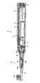
- FIG. 2 is a cross-sectional view illustrating an internal configuration example of the electric toothbrush
- FIG. 3 is a perspective view illustrating an external appearance example of a display system including the electric toothbrush. It is.
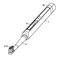
- the electric toothbrush 1 includes a main body 2 (hereinafter also simply referred to as “main body 2”) in which a motor 10 that is a driving source is incorporated, and a vibration member 5 that vibrates when the motor 10 is driven. Therefore, the vibration member 5 is regarded as an electric toothbrush main body, and the rotation speed of the motor 10 corresponds to the vibration frequency of the electric toothbrush main body.
- the main body 2 has a generally cylindrical shape, and also serves as a handle portion for the user to hold with his / her hand when brushing his / her teeth.
- the electric toothbrush 1 of the present embodiment includes a charger 100 for charging the electric toothbrush 1 on which the main body 2 is mounted, and a display 110 for outputting a brushing result.
- the main body 2 is provided with a switch S for turning on / off the power source and switching an operation mode of the motor 10 described later. Further, inside the main body 2, there are a motor 10 (for example, a direct current motor) that is a driving source, a driving circuit 12, a rechargeable battery 13 that is a power source with a rated output of 2.4V for supplying power to each part, and a coil for charging. 14 etc. are provided. When charging the rechargeable battery 13, the main body 2 is simply placed on the charger 100 and can be charged in a non-contact manner by electromagnetic induction.
- a motor 10 for example, a direct current motor
- a driving circuit 12 for example, a driving circuit 12
- a rechargeable battery 13 that is a power source with a rated output of 2.4V for supplying power to each part
- the drive circuit 12 stores a CPU (Central Processing Unit) 120 that executes various operations and controls, a program, various setting values, and a memory 121 that stores tables TB1 to TB5 (described later), a timer 122, data A transmission unit 123 and the like are included.
- the data transmission unit 123 performs wireless communication with the data reception unit 112 of the display device 110.
- the display device 110 includes a display 111 for outputting data such as a brushing result received by the data receiving unit 112.
- the main body 2 is integrally provided with a display unit 16 for displaying the brushing result.
- a display unit 16 for displaying the brushing result.
- FIG. 3 the appearance of the electric toothbrush 1 attached to the charger 100 is shown in association with the display device 110.
- a multi-axis (here, x, y, z three-axis) acceleration sensor 15 is provided in the main body 2, in order to detect the posture of the electric toothbrush 1, for example.
- the acceleration sensor 15 is installed so that the x-axis is parallel to the brush surface, the y-axis is coincident with the longitudinal direction of the main body 2, and the z-axis is perpendicular to the brush surface. Is done. That is, when the main body 2 is placed on the charger 100, the gravitational acceleration vector is parallel to the y-axis, and when the brush surface is directed upward, the gravitational acceleration vector is parallel to the z-axis.
- each axis of the acceleration sensor 15 is input to the CPU 120 and used to detect the three-dimensional posture of the brush.
- a piezoresistive type, a capacitance type, or a heat detection type MEMS (Micro Electro Mechanical Systems) sensor can be preferably used. This is because the MEMS sensor is very small and can be easily incorporated into the body 2.
- the form of the acceleration sensor 15 is not limited to this, and an electrodynamic sensor, a strain gauge sensor, a piezoelectric sensor, or the like may be used.
- a band pass filter (low pass filter) for removing dynamic acceleration components and noise may be provided. Further, noise may be reduced by smoothing the output waveform of the acceleration sensor.
- the vibrating member 5 includes a stem portion 20 fixed to the main body 2 side and a brush component 21 attached to the stem portion 20.
- a brush 210 is planted at the tip of the brush component 21. Since the brush part 21 is a consumable part, it is configured to be detachable from the stem portion 20 so that it can be replaced with a new one.
- the brush component 21 of the vibration member 5 includes a brush portion where the brush 210 is disposed and a handle portion located on the main body 2 side.
- the configuration in which the brush part 21 including a relatively long handle portion is replaced is shown.
- the brush component alone or the brush component including the brush portion and the short handle portion may be replaced. Good. That is, all or part of the handle may be included in the main body.
- the stem portion 20 is made of a resin material.
- the stem portion 20 is attached to the main body 2 via an elastic member 202 made of an elastomer.
- the stem portion 20 is a cylindrical member whose tip (brush side end) is closed, and has a bearing 203 at the tip inside the tube.
- the tip of the eccentric shaft 30 connected to the rotating shaft 11 of the motor 10 is inserted into the bearing 203 of the stem portion 20.
- the eccentric shaft 30 has a weight 300 in the vicinity of the bearing 203, and the center of gravity of the eccentric shaft 30 is deviated from the center of rotation. A minute clearance is provided between the tip of the eccentric shaft 30 and the bearing 203.
- the electric toothbrush 1 further includes an electrode-type contact detection unit 50 for detecting the presence or absence of contact or approach.
- the contact detection unit 50 detects contact or proximity to a living body, that is, the buccal mucosa and the tongue, during brushing.
- the contact detection unit 50 includes an electrode unit 52 and a detection unit 54 for detecting impedance from the electrode unit 52.
- the detection unit 54 may be mounted in the drive circuit 12.
- the detection unit 54 in the drive circuit 12 can detect the impedance by detecting the current flowing through the electric circuit of the electrode unit 52.
- Contact or proximity to the buccal mucosa and tongue is detected by the impedance value.
- the CPU 120 supplies a drive signal (for example, PWM ((Pulse Width Modulation) signal)) according to the operation mode to the motor 10 to rotate the rotating shaft 11 of the motor 10.
- the eccentric shaft 30 also rotates with the rotation of the rotating shaft 11.
- the eccentric shaft 30 moves so as to turn around the center of rotation because the center of gravity is shifted, so that the tip of the eccentric shaft 30 repeatedly collides with the inner wall of the bearing 203, and the stem portion 20 and
- the motor 10 vibrates (moves) at high speed with the mounted brush component 21. That is, the motor 10 serves as a drive unit that vibrates (moves) the brush, and the eccentric shaft 30 vibrates the output (rotation) of the motor 10. It plays the role of a motion transmission mechanism (motion conversion mechanism) that converts the vibration into the member 5.
- a motion transmission mechanism motion conversion mechanism
- the user can perform brushing by holding the main body 2 by hand and applying a brush 210 that vibrates at high speed to the teeth.
- the CPU 120 monitors the continuous operation time using the timer 122, and automatically stops the vibration of the brush when a predetermined time (for example, 2 minutes) elapses.
- the eccentric shaft 30 that is a motion transmission mechanism is included in the vibration member 5, and in particular, the weight 300 is disposed in the vicinity of the brush 210. Therefore, the portion of the brush 210 can be vibrated efficiently.
- the vibration member 5 stem part 20
- the vibration of the vibration member 5 is difficult to be transmitted to the main body 2. Therefore, the vibration of the main body 2 and the hand when brushing teeth can be reduced, and the usability can be improved.
- the electric toothbrush 1 accurately estimates the brushing region based on the brush posture (posture information) detected by the acceleration sensor 15 and the detection result of the contact detection unit 50, thereby Each brushing evaluation is realized.
- Various evaluation items are conceivable, but here, three items of brushing time, brush angle, and brush pressure are evaluated.
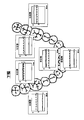
- the upper and lower dentitions are represented by “maxillary anterior cheek side”, “maxillary anterior tongue side”, “maxillary left cheek side”, “maxillary left tongue side”, “maxillary right cheek side”, “maxillary right tongue” 12 parts of “side”, “mandibular anterior cheek side”, “mandibular anterior tongue side”, “mandibular left cheek side”, “mandibular left lingual side”, “mandibular right cheek side”, “mandibular right lingual side” Divide into
- the division of the dentition is not limited to this, and may be a broader division or a finer division.
- upper, lower, left and right meshing surfaces may be considered.
- FIG. 4 is a flowchart of the main routine
- FIGS. 5 to 7 and FIG. 21 are flowcharts showing details of each process of the main routine. Note that the processing described below is processing executed by the CPU 120 according to a program stored in the memory 121 unless otherwise specified.
- step S (hereinafter simply referred to as S) 5).
- the posture (tilt) of the brush is detected based on the output of the acceleration sensor 15 (S10).
- the CPU 120 estimates a brushing part based on at least the posture detected in S10 (S20).
- the CPU 120 performs brushing time measurement (S30), brush angle estimation (S40), and brush pressure detection (S50). These pieces of information are recorded in the memory 121 for each part (see FIG. 10) and output (S55).
- the processes of S10 to S55 are repeatedly executed at regular time intervals.
- the CPU 120 determines, for each part, based on the brushing information (brushing time, brush angle, brush pressure) recorded in the memory 121.
- the brushing result is evaluated, and the evaluation result is output to the display 110 (S60).
- the brushing information in the memory 121 is cleared each time the electric toothbrush 1 is turned on.
- FIG. 5 is a flowchart of the posture detection process (S10).
- CPU 120 obtains the respective outputs Ax, Ay, Az of x, y, z from the acceleration sensor 15 (S100).
- Ax represents an acceleration component in the x direction
- Ay represents an acceleration component in the y direction
- Az represents an acceleration component in the z direction.
- A (Ax, Ay, Az) is called an attitude vector.
- the CPU 120 determines whether the brushing part is the upper jaw or the lower jaw based on the output Az of the acceleration sensor in the z direction (S700).
- the determination is focused on the fact that the brush surface is upward rather than a little, and when brushing the lower jaw, the brush surface is not less than downward.
- Az> 0 is established, the lower jaw (S801) is determined, and when Az ⁇ 0, the upper jaw (S701) is determined.
- the CPU 120 determines whether or not the brushing part is an anterior tooth based on the output Ay of the acceleration sensor in the y direction (S702).
- the toothbrush main body 2 is relatively horizontal when brushing the front teeth, but the determination is focused on the fact that the toothbrush main body 2 must be inclined because of interference with the lips when brushing the molars.
- Ay ⁇ threshold a it is determined that the upper jaw is an anterior tooth (S703).
- the CPU 120 determines whether the brushing part is the buccal side or the tongue side based on the output Ax of the acceleration sensor in the x direction (S704). This determination is focused on the fact that the direction of the brush is reversed between the cheek side and the tongue side. When Ax> 0 is established, it is determined as “upper maxillary cheek side” (S705), and when Ax ⁇ 0 is established, it is determined as “upper maxillary tongue side” (S706).
- the CPU 120 determines the direction of the brush based on the output Ax of the acceleration sensor in the x direction (S707).
- the brushing part is determined as “upper right cheek side or upper left tongue side” (S708), and when Ax ⁇ 0 is satisfied, it is determined as “upper left cheek side or upper maxillary right tongue side”. (S712).
- the CPU 120 narrows down the parts based on the brushing part determined in the previous process (process one clock before) (S709, S713).
- the previous brushing part is any one of “upper front cheek side, upper right cheek side, upper maxillary tongue side, lower maxillary front cheek side, lower jaw right cheek side, lower jaw right tongue side”
- the current brushing site is estimated to be “maxillary right cheek side” (S710), and the previous brushing site is “maxillary anterior tongue side, maxillary left cheek side, maxillary left lingual side, mandibular anterior tongue side, mandibular left cheek. If it is one of the left side and the lower left lingual side, it is estimated that the current brushing site is the upper left lingual side (S711).
- the previous brushing site is any one of “maxillary anterior cheek side, maxillary left cheek side, maxillary left lingual side, mandibular anterior cheek side, mandibular left cheek side, mandibular left lingual side” It is estimated that the part is “upper left cheek side” (S714), and the previous brushing part is “upper maxillary tongue side, maxillary right cheek side, maxillary right tongue side, mandibular anterior tongue side, mandibular right cheek side, mandibular right If it is one of “lingual side”, it is estimated that the current brushing site is “maxillary right lingual side” (S715). The reason for this estimation is that there is a high probability that the brushing part is moved so that the amount of movement and the direction change of the brush are minimized.
- the CPU 120 determines whether or not it is an anterior tooth based on the output Ay of the acceleration sensor 15 in the y direction (S802).
- the toothbrush main body 2 is relatively horizontal when brushing the front teeth, but the determination is focused on the fact that the toothbrush main body 2 must be inclined because of interference with the lips when brushing the molars. If Ay ⁇ threshold value b holds, the brushing part is determined to be the lower anterior tooth (S803).
- the CPU 120 determines whether the brushing part is the buccal side or the tongue side based on the output Ax of the acceleration sensor in the x direction (S804). This determination is focused on the fact that the direction of the brush is reversed between the cheek side and the tongue side.
- Ax ⁇ 0 is established, it is determined as “mandibular anterior cheek side” (S805), and when Ax ⁇ 0 is established, it is determined as “mandibular anterior tongue side” (S806).
- the CPU 120 determines the direction of the brush based on the output Ax of the acceleration sensor in the x direction (S807).
- Ax> 0 it is determined as “mandibular right cheek side or mandibular left tongue side” (S808), and when Ax ⁇ 0 is established, it is determined as “mandibular left cheek side or mandibular right tongue side” ( S812).
- the previous brushing part is any one of “mandibular anterior cheek side, mandibular right cheek side, mandibular right tongue side, mandibular anterior cheek side, maxillary right cheek side, maxillary right tongue side” Is estimated to be “mandibular right buccal side” (S810), and the previous brushing site is “mandibular anterior tongue side, mandibular left cheek side, mandibular left tongue side, maxillary anterior tongue side, maxillary left buccal side, maxillary left tongue If it is “side”, it is estimated that the current brushing part is “the lower left lingual side” (S811).
- the previous brushing site is any of “mandibular anterior cheek side, mandibular left cheek side, mandibular left lingual side, maxillary anterior cheek side, maxillary left cheek side, maxillary left lingual side” It is estimated that the region is “mandibular left cheek side” (S814), and the previous brushing region is “mandibular anterior tongue side, mandibular right cheek side, mandibular right tongue side, maxillary anterior tongue side, maxillary right cheek side, maxillary right If it is either “lingual side”, the current brushing site is estimated to be “mandibular right lingual side” (S815).
- the current brushing sites are “maxillary anterior cheek side” (S705), “maxillary anterior tongue side” (S706), “maxillary right cheek side” (S710), and “maxillary left lingual side” (S711).
- the above determination algorithm is merely an example, and any determination algorithm may be used as long as the brushing part can be specified from the outputs Ax, Ay, and Az of the acceleration sensor 15.
- secondary variables obtained by appropriately combining Ax, Ay, and Az may be used for determination.
- the secondary variable for example, Ay / Az, Ax ⁇ Ax + Ay ⁇ Ay, Az ⁇ Ax, and the like can be arbitrarily set.
- the brushing part may be determined.
- the x-axis angle with respect to the gravitational acceleration direction is defined as a roll angle ⁇
- the y-axis angle with respect to the gravitational acceleration direction is defined as a pitch angle ⁇
- the z-axis angle with respect to the gravitational acceleration direction is defined as a yaw angle ⁇ .
- the threshold used for determination can be determined from the results of clinical experiments or the like.
- FIG. 10 shows an example of brushing information recorded in the memory 121.
- FIG. 10 is an example of a state where the lower jaw left cheek side is brushed. Before the lower jaw left cheek side, the upper jaw cheek side is brushed for 7.5 seconds, and the upper jaw left cheek side is brushed for 12.2 seconds. Note that “-” indicates that no data is recorded, that is, the portion has not been brushed yet.
- the CPU 120 counts up the brushing time of the brushing part (in the example of FIG. 10, lower left cheek side) estimated in S20. For example, if the processing of S10 to S50 in FIG. 4 is executed once every 0.1 second, the brushing time on the lower jaw left cheek side is counted up by +0.1 to 2.1 seconds.
- the cumulative value of the brushing time is recorded. That is, for example, when the brushing part moves to the upper left cheek side again, the stored brushing time is not reset, but the brushing time is added to the stored value of 12.2 seconds.
- the CPU 120 estimates the brush angle based on the posture (output of the acceleration sensor 15) detected in S10, and determines the brush angle of the current brushing part (the lower jaw left cheek side in the example of FIG. 9). Update the value. At this time, it is preferable that the CPU 120 calculates and records the average value of the brush angle from the stored brush angle value and the current estimated value.
- the brush angle is the contact angle of the brush with respect to the tooth axis (axis along the tooth head and root).
- the brush angle is preferably in the range of 35 to 55 degrees.
- the brush angle can be estimated from, for example, the acceleration component Az in the z direction. As shown in FIG. 12, when the brush angle is about 90 degrees, Az is almost 0, and as the brush angle becomes smaller, the value of Az increases. Thus, the value of Az changes significantly according to the brush angle. Because it does. Since the acceleration component Ax in the x direction also changes according to the brush angle, the brush angle is estimated from Ax instead of Az, or the brush angle is calculated from both Ax and Az (the direction of the combined vector of Ax and Az). It is also preferable to estimate.
- the brush angle may be calculated as a continuous amount or may be a rough estimate such as “less than 35 degrees”, “35 degrees to 55 degrees”, or “55 degrees or more”.
- the CPU 120 estimates (detects) the brush pressure based on the output of the acceleration sensor 15, and updates the brush pressure value of the current brushing site (in the example of FIG. 10, the lower jaw left cheek side). At this time, the CPU 120 preferably calculates and records the average value of the brush pressure from the value of the brush pressure stored in the memory 121 and the current detected value.
- the brush pressure of the electric toothbrush 1 may be lower than that of an ordinary toothbrush, it is said that most people who have started using the electric toothbrush 1 tend to exceed the brush pressure.
- the optimum value of the brush pressure is about 100 to 200 g.
- the CPU 120 evaluates the brushing result for each part based on the brushing information recorded in the memory 121 in S55 or S60 of FIG. 4, and outputs the evaluation result to the display 110 (display 111).
- FIG. 13 is an output example of the evaluation result of the brushing time.
- the CPU 120 reads the brushing time of each part from the memory 121 and evaluates, for example, “insufficient” for less than 7 seconds, “good” for 7 to 15 seconds, and “excess” for more than 15 seconds.
- the evaluation result is transmitted to the display device 110.
- a tooth row is drawn on the display 111 of the display device 110, and the corresponding part in the tooth row is a color corresponding to the evaluation result (“insufficient” is white, “good” is yellow, “excess” is red, etc.) Lights on. By confirming such a display, the user can intuitively grasp which part of the dentition is insufficient (or excessive).
- FIG. 14 is an example of output of brush angle evaluation results.
- the evaluation is made in three stages, “less than 35 degrees”, “35 degrees to 55 degrees”, and “55 degrees or more”, and each part in the dentition is lit in a color according to the evaluation result.
- the plaque removing power is inferior to the optimal brush angle, so that the desired brushing effect may not be obtained or the brushing may take time. If the evaluation of the brush angle for each part is output as shown in FIG. 14, the user can be made aware of brushing by the correct brush angle.
- FIG. 15 is an output example of the evaluation result of the brush pressure. For example, if it is less than 100 g, it is evaluated as “insufficient”, 100 g to 200 g as “good”, and more than 200 g as “excessive”, and each part in the dentition is lit in a color corresponding to the evaluation result.
- the brush pressure is not appropriate, problems such as a decrease in plaque removal power, a decrease in brush life, and an increase in burden on the gums may occur. However, it is difficult for the user to understand how much force is applied to achieve the optimum brush pressure.
- the evaluation of the brush pressure for each part is output as shown in FIG. 15, the user can be taught the appropriate brush pressure and can be made aware of the brushing by the correct brush pressure.
- FIG. 16 is an output example of the evaluation result of the brushing index.
- the brushing index is an index for comprehensively evaluating a plurality of evaluation items (brushing time, brush angle, brush pressure), and represents the achievement level of brushing.
- the formula for calculating the brushing index may be defined in any way.
- the brushing time and the brush pressure are each set to a maximum of 35 points
- the brush angle is set to a maximum of 30 points
- the total of these values maximum of 100 points
- the brushing index is evaluated in three stages of “excellent”, “good”, and “impossible”.
- 80 or more brushing indexes are evaluated as “excellent”, 60 to 80 points as “good”, and less than 60 points as “impossible”.
- the initial state before brushing is shown on the left side of FIG. 16, and the evaluation after brushing is shown in association with each part of the dentition of the jaw shown schematically on the right side.
- the posture of the electric toothbrush 1 and the brushing part can be identified with high accuracy by using the output of the acceleration sensor 15. Therefore, it is possible to evaluate the brushing result with fine divisions (parts), and to provide a user with a useful and reliable evaluation guideline. Moreover, since the acceleration sensor 15 is small, there is an advantage that it can be easily incorporated into the body of the electric toothbrush 1.
- evaluation results in FIGS. 13 to 16 may be displayed on the display 111 simultaneously or sequentially. In the latter case, display switching may be performed automatically or by a user's button operation.
- the result is automatically displayed when the electric toothbrush 1 is turned off.
- toothbrushing is performed at a location different from the installation location of the display device 110, for example, when the user presses a button provided on the display device 110 or the toothbrush body 2, the display is performed from the toothbrush body 2.
- the brushing information and evaluation results stored in the memory 121 may be printed.
- a printer (not shown) may be mounted on the charger or display, or print data may be transmitted from the toothbrush body, charger or display to an external printer.
- a function of transferring brushing information and evaluation result data to an external device (not shown) (such as a personal computer, a mobile phone, or a PDA (Portable Digital Assistant)) by wireless communication or wired communication is also preferable.
- a memory card slot (not shown) may be provided in the toothbrush main body, charger, display, etc. so that brushing information and evaluation result data can be recorded in an external memory card.
- optimum values target values
- a brush angle of 35 ° to 55 ° is preferable in order to effectively scrape food residue and plaque from the periodontal pockets and teeth between the brush tips.
- a larger angle for example, 55 to 90 degrees
- the brush angle is preferably about 0 degree with respect to the mating surface of the molar.
- the optimal brushing time, brush angle, and brush pressure can be determined not from the viewpoint of the brushing effect but from the viewpoint of avoiding damage to tissues such as gums. Thus, if an optimum value is set for each part and evaluation is performed, a more useful and reliable evaluation guideline can be provided.
- the brush pressure is detected (estimated) using any one of Ax, Ay, and Az that are voltage signals output from the acceleration sensor 15.
- FIG. 17 shows a functional configuration for brush pressure estimation according to the embodiment.
- Each unit in FIG. 17 is realized by a combination of a program and a circuit whose execution is controlled by the CPU 120. These programs are stored in advance in a predetermined area of the memory 121.
- the CPU 120 reads out the program from the memory 121 and executes the instruction code of the read program, thereby realizing the functions of the respective units.
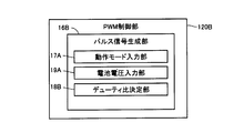
- the CPU 120 includes a brush pressure estimation unit 1201 for estimating the brush pressure and a PWM control unit 120A for driving the motor 10 according to the PWM control.
- the brush pressure estimation unit 1201 consumes the dynamic acceleration component processing unit 153, the static acceleration component processing unit 155, and the motor 10 that process the dynamic acceleration component and static acceleration component signals of the electric toothbrush 1 among the output signals of the acceleration sensor 15.
- the output signal of the current detection unit 104 indicating current (supply current) is input, the consumption current detection unit 156 that detects the consumption current of the motor 10 based on the input signal, the table TB1 of the memory 121 are searched, and the search result is output.
- a table search unit 157 is included.
- the PWM control unit 120A includes a pulse signal generation unit 16A that generates a pulse signal for controlling driving of the motor 10.
- the pulse signal generation unit 16A generates a pulse signal using a pulse signal generation circuit (not shown).
- the pulse signal generation unit 16A includes an operation mode input unit 17A that inputs an operation mode instructed by the user operating the switch S, and a duty ratio determination unit 18A that determines the duty ratio of the pulse signal based on the input operation mode.
- Have The pulse signal generation unit 16A generates and outputs a pulse signal having the determined duty ratio.
- the output pulse signal is given to the motor 10 as a drive signal.
- FIG. 18 schematically shows the acceleration sensor 15 and its peripheral circuits.
- the filter unit 103 is connected to the output stage of the acceleration sensor 15.
- the filter unit 103 receives an output signal from the acceleration sensor 15 and passes only a signal in a predetermined frequency band.
- a BPF (Band Pass Filter) 151 and an HPF (High Pass Filter) connected in parallel to the output stage of the BPF 151.
- a dynamic acceleration component processing unit 153 is connected to the output stage of the HPF 152, and a static acceleration component processing unit 155 is connected to the output stage of the LPF 154.
- the HPF 152 passes only a signal having a frequency equal to or higher than a predetermined cutoff frequency (for example, 90 Hz) from the input signal from the BPF 151 and outputs the signal.
- the LPF 154 passes and outputs only a signal having a frequency equal to or lower than a predetermined cutoff frequency (for example, several Hz) among the input signals from the BPF 151.
- the dynamic acceleration component processing unit 153 receives and processes the signal 10D output from the HPF 152, thereby detecting the frequency of the electric toothbrush 1 body accompanying the rotation operation of the motor 10.
- the signal 10D output from the HPF 152 corresponds to a signal having a frequency (for example, a frequency band of 100 Hz to 300 Hz) caused by the rotation (vibration) of the motor 10.
- the static acceleration component processing unit 155 receives and processes the signal 10S output from the LPF 154.
- the input signal 10S corresponds to a signal having a frequency (for example, a frequency band of several Hz) resulting from an operation of changing the posture of the brush, such as a user who is brushing teeth twists the electric toothbrush 1. Therefore, the signal 10S corresponds to a signal of a posture information component of the electric toothbrush 1 main body.
- FIG. 19A shows an example of the waveform of the output signal of the BPF 151 shown in FIG. 18 as time elapses.
- a vibration component caused by a rotational operation of the motor 10 which is a high frequency component of 100 Hz to 300 Hz is added to a signal 10S which is a low frequency component of several Hz or less (indicated by a thick solid line in the figure).
- the signal 10D (indicated by a thin solid line in the figure) is superimposed, but the signals 10D and 10S can be separated and output by passing through the filter unit 103 described above.
- FIG. 19B the signal 10D in a certain time zone shown in FIG. 19A is extracted and enlarged.
- the dynamic acceleration component processing unit 153 receives the signal 10D, and detects the slope of the waveform for each predetermined period T (hereinafter referred to as sampling period T) with respect to the waveform of the input signal 10D. This inclination can be detected by differentiating the waveform.
- the dynamic acceleration component processing unit 153 detects the slope (positive slope or negative slope) of the waveform indicated by the signal 10D for each sampling period T, and the length of the period in which the positive slope continues or the negative slope is detected. The length of the continuous period and the timing of switching from a positive slope to a negative slope (or from a negative slope to a positive slope) are detected. Based on the detection result, the frequency of the signal 10D, that is, the frequency of the electric toothbrush 1 is detected. The detected frequency is output to the table search unit 157.
- the frequency detection method is not limited to the method shown in FIG.
- extreme values maximum value and minimum value
- the frequency of the signal 10D that is, the frequency of vibration
- the frequency of the signal 10D is determined based on the number of maximum values and minimum values detected in a predetermined time period. May be detected.
- the graph of FIG. 20 shows the correlation between the frequency and the load (here, brush pressure).
- the graph in FIG. 20 indicates data based on the experiment results of the inventors.
- the vertical axis represents the frequency (Hz)
- the horizontal axis represents the load (gram: g) applied to the motor 10.
- the motor 10 rotates at the fastest speed when there is no load (no load) in a state where the same drive signal is given from the PWM control unit 120A, and the rotation speed decreases as the load increases.
- the frequency of the electric toothbrush 1 due to the rotation of the motor 10 indicates the maximum frequency V1
- the brush 210 is pressed against the teeth so that the entire brush 210 is loaded.
- the brush pressure increases.
- the load applied to the motor 10 increases, the rotational speed of the motor 10 decreases, and the frequency decreases.
- the frequency of the motor 10 is detected in the range of the appropriate frequency V2 to V3.
- an excessive load of 500 g is applied to the entire brush 210, for example, when the brush 210 is strongly pressed against the teeth, an excessive load is applied to the motor 10, and the frequency is the frequency at the time of excessive pressure. It changes in the range of V4-0.
- the brush pressure can be uniquely determined (detected) based on the frequency of the signal 10D, that is, based on the frequency.
- the frequency data indicated by the characteristics of the graph of FIG. 20 and the corresponding brush pressure data are associated and stored in advance in the table TB1.
- the table search unit 157 searches the table TB1 based on the vibration frequency output from the dynamic acceleration component processing unit 153, and reads the brush pressure corresponding to the vibration frequency from the table TB1 based on the search result.
- the brush pressure estimation unit 1201 can detect (estimate) the brush pressure.
- FIG. 21 shows a schematic flowchart of brush pressure detection (estimation) processing according to the present embodiment.
- the brush pressure estimation unit 1201 inputs the output signal of the acceleration sensor 15 via the filter unit 103 (step SS (hereinafter simply referred to as SS) 3).
- the dynamic acceleration component processing unit 153 detects the vibration frequency according to the above-described procedure (detection of vibration frequency) (SS5).
- the table search unit 157 searches the table according to the above-described procedure (detection of brush pressure based on frequency) (SS7), and detects the brush pressure ( SS9). Thereby, the brush pressure is determined (estimated).
- the brush pressure estimation unit 1201 estimates the brush pressure based only on the vibration frequency of the motor 10 in the above-described procedure, but may detect the vibration frequency based on the current supplied to the motor 10.
- FIG. 22 shows a graph of load characteristics of the motor 10 according to the present embodiment.
- the vertical axis of the graph of FIG. 22 shows the rotation speed (rpm) of the motor 10 and the supply current to the motor 10 (that is, the consumption current of the motor 10) (unit: A).
- the torque (load) applied to the motor 10 is shown on the horizontal axis.
- This torque corresponds to the brush pressure described above.
- a straight line SA in FIG. 22 represents an ideal characteristic that the current supplied to the motor 10 increases as the torque (load) increases.
- the straight line RA represents the characteristic that the rotational speed of the motor 10 decreases as the torque (load) increases.
- the supply current data pointed to by the straight line SA and the corresponding torque data are detected in advance by experiments and are associated with each other and stored in the table TB2.
- the supply current to the motor 10 is detected by the current consumption detector 156 using the current detector 104.
- the current detection unit 104 corresponds to a resistance element connected to the input stage of the drive signal of the motor 10.
- the consumption current detection unit 156 detects the current supplied to the motor 10 by measuring the voltage applied to the resistance element and dividing the measured voltage by the resistance value of the resistance element. Note that detection using a current sensor may be used instead of detection using a resistance value.
- the supply current to the motor 10 increases as the torque increases from 0, but the motor 10 generates heat as the supply current increases. That is, when the torque indicates the predetermined value TH (> 0), if the current of the value SA1 is supplied to the motor 10, if the torque exceeds the predetermined value TH, the supply current (> SA1) to the motor 10 ), The current consumed for heat generation increases, and the straight line SA does not show the ideal correlation as shown in FIG.
- the brush 10 is based on the supply current of the motor 10 according to the relationship between the supply current of the motor 10 and the torque indicated by the straight line SA. It is possible to detect the pressure.
- the table TB1 is searched based on the frequency as described above, not the current consumption. Detect brush pressure.
- the current value SA1 is detected in advance by experiment and stored in the memory 121.
- the brush pressure estimation unit 1201 compares the current value detected by the current consumption detection unit 156 with the current value SA1 read from the memory 121, and controls the table search unit 157 based on the comparison result.
- the table search unit 157 performs the table TB2 based on the current consumption value of the motor 10 detected by the current consumption detection unit 156. Control to search.
- the table search unit 157 reads the corresponding torque (brush pressure) from the table TB2 based on the search result.
- the table search unit 157 is controlled to search the table TB1 based on the frequency as described above.
- the table search unit 157 reads the corresponding brush pressure from the table TB1 based on the search result.
- the brush pressure estimation unit 1201 can accurately estimate the brush pressure based on one or both of the current consumption and the vibration frequency of the motor 10.
- FIG. 23 schematically shows the change with time of the output voltage of the rechargeable battery 13.
- the output voltage indicates the remaining battery level of the rechargeable battery 13.
- the graph of FIG. 23 shows the characteristics obtained by experiments.
- the vertical axis represents the output voltage (unit: V) of the battery, and the horizontal axis represents the elapsed time t.
- a nickel metal hydride battery is generally used as the rechargeable battery 13.
- the rated output of the rechargeable battery 13 is assumed to be 2.4 V, for example.
- the output voltage can be maintained at the rated output (2.4V), but the output voltage decreases as the usage time elapses.
- the output voltage is maintained at the rated voltage (2.4V) until the end of the battery life (time t1).
- time t1 When the time t1 is reached, the output voltage becomes zero.
- typical batteries do not exhibit such ideal characteristics. That is, as shown by the broken line in FIG.
- the rechargeable battery 13 cannot gradually maintain the rated voltage (2.4 V), and the elapsed time from the start of use becomes time t2 ( ⁇ t1). When the output voltage becomes 2.0 V, it rapidly decreases thereafter. When the output voltage of the rechargeable battery 13 is 2.0 V or less, the electric toothbrush 1 cannot exhibit a sufficient operating capability and cannot obtain a sufficient frequency.
- the CPU 120 includes a PWM control unit 120B in FIG. 24 instead of the PWM control unit 120A in FIG.
- PWM control unit 120B includes a pulse signal generation unit 16B that generates a pulse signal for controlling driving of motor 10.
- the pulse signal generator 16B generates a pulse signal using a pulse signal generation circuit (not shown).
- the pulse signal generation unit 16B receives an operation mode input unit 17A for inputting an operation mode instructed by the user by operating the switch S, and a detection signal of the voltage monitor 102.
- the pulse signal generator 16B Based on the input detection signal, the pulse signal generator 16B The battery voltage input unit 19A that detects the output voltage and the duty ratio determination unit 18B that determines the duty ratio of the pulse signal based on the operation mode and the output voltage of the rechargeable battery 13 are included. The pulse signal generation unit 16B generates and outputs a pulse signal having the determined duty ratio. The pulse signal is given to the motor 10 as a drive signal.
- the duty ratio refers to the length of a period in which the voltage level with respect to the length of one cycle is ON when the length of one cycle of the pulse signal is 100%.
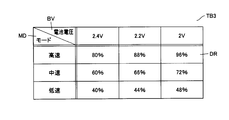
- FIG. 26 shows an example of a table TB3 referred to by the duty ratio determination unit 18B in order to change the duty ratio.
- the table TB3 stores the duty ratio DR for making the electric power supplied to the motor 10 constant corresponding to each set of the operation mode type MD of the electric toothbrush 1 and the output voltage value BV of the rechargeable battery 13. Is done.
- the data of the table TB3 is acquired in advance by experiments.
- 2.4 V, 2.2 V, and 2 V are stored as the output voltage value BV
- the operation mode type MD is “high-speed” mode that vibrates at high speed, and “medium-speed” mode that vibrates at a lower speed than that.
- three types of “low speed” modes that vibrate at a lower speed are stored. Note that the number of types of output voltage values BV and the number of types of operation modes MD to be stored are not limited thereto.
- the operation mode input unit 17A inputs the type of operation mode specified by the user operating the switch S, and the battery voltage input unit 19A detects the output voltage of the rechargeable battery 13.
- the duty ratio determination unit 18B searches the table TB3 in FIG. 26 based on the set of the input operation mode type and the detected output voltage. Based on the search result, the duty ratio DR corresponding to the set is read from the table TB3.
- the pulse signal generation unit 16B generates and outputs a pulse signal having the read duty ratio DR. The output pulse signal is given to the motor 10 as a drive signal.
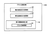
- FIG. 27 shows a functional configuration of a brush pressure estimation unit 1202 having a brush pressure search function.
- a brush pressure estimation unit 1202 may be used instead of the brush pressure estimation unit 1201 of FIG.
- the brush pressure estimation unit 1202 includes a dynamic acceleration component processing unit 153, a static acceleration component processing unit 155, and a differential frequency detection unit 158 including a brush pressure search unit 159.
- the rest of the configuration excluding the differential frequency detection unit 158 of the brush pressure estimation unit 1202 is the same as that of the brush pressure estimation unit 1201, and the description thereof will be omitted.
- the difference frequency detection unit 158 receives the frequency (Hz) output from the dynamic acceleration component processing unit 153, and detects the difference between the input frequency and the no-load frequency. Then, the brush pressure is detected based on the detected difference. Thereby, the brush pressure is estimated.
- the tables TB4 and TB5 of FIGS. 28 and 29 are searched by the brush pressure search unit 159.
- the table TB4 of FIG. 28 when the load applied to the motor 10 is 0 (no load) corresponding to each set of the type of the operation mode MD of the electric toothbrush 1 and the output voltage BV of the rechargeable battery 13.
- the frequency (Hz) DV is stored in advance.
- the number of types of operation mode MD and the type of output voltage BV stored in the table TB4 are not limited to this.
- the brush pressure PR is stored in advance corresponding to the difference DF between the frequency DV read from the table TB4, the frequency detected by the dynamic acceleration component processing unit 153, and the difference DF. Is done. Data in the tables TB4 and TB5 are detected in advance by experiments.
- step S ⁇ b> 5 the difference frequency detection unit 158 receives a signal indicating the output voltage value of the rechargeable battery 13 from the voltage monitor 102.
- the brush pressure search unit 159 of the differential frequency detection unit 158 searches the table TB4 based on the type of operation mode instructed by the user input from the switch S and the voltage value indicated by the input signal from the voltage monitor 102. To do. Based on the search result, the frequency DV corresponding to the set of the voltage value and the operation mode is read from the table TB4.
- the difference frequency detection unit 158 stores the no-load frequency DV read from the table TB4 in a predetermined area of the memory 121.
- step S5 When the initialization process (step S5) is completed, brush pressure is generated by brushing, and the torque of the motor 10 increases. Accordingly, the frequency of the motor 10 detected by the dynamic acceleration component processing unit 153 also increases.
- the differential frequency detection unit 158 detects the frequency sequentially detected by the dynamic acceleration component processing unit 153 and the frequency DV read from a predetermined area of the memory 121. Is detected (calculated). Then, the brush pressure search unit 159 searches the table TB5 of the memory 121 based on the detected difference. Based on the search result, the brush pressure PR corresponding to the difference DF that matches the detected difference is read from the table TB5. Thereby, the brush pressure (brush pressure PR) is detected (estimated).
- the difference between the unloaded frequency corresponding to the output voltage (remaining battery level) of the rechargeable battery 13 and the frequency when the load is applied corresponds to the magnitude of the load, that is, the brush pressure.
- the magnitude of the load that is, the brush pressure
- the magnitude of the load can be estimated based on the difference between the vibration frequency when the motor 10 is unloaded and the vibration frequency when there is a load.
- the brush pressure can be displayed on the display unit 110 in FIG. 3, but can also be displayed on the display unit 16.
- the display unit 16 includes a light emitting unit such as an LED (Light Emitting Diode), and is provided at the end of the main body 2 so that the user can easily confirm at the time of brushing.
- the display unit 16 is arranged so as to go around the housing of the substantially cylindrical main body 2. When placed at the end, it can be confirmed by mirror reflection.
- the display unit 16 may be provided at the end of the main body 2 on the brush 210 side.
- the lighting state of the LED of the display unit 16 is changed according to the detected brush pressure. For example, the LED blinks at a higher speed or the brightness of the LED is increased as the brush pressure is evaluated to be higher. Alternatively, the light may be lit in red when the brush pressure is evaluated as high, and may be lighted in green when the brush pressure is evaluated as low.
- the detected frequency may be notified by displaying via the display 110 or the display unit 16.
- the manner of reporting the brush pressure and the vibration frequency is not limited to that using the display unit 16 and may be an output using sound or voice.
- the DC motor 10 may not be used as the drive source.
- an actuator using a solenoid, a piezoelectric element, an ultrasonic vibrator, an artificial muscle, or the like may be used.
Abstract
ケア部材を用いて口腔をケアする口腔ケア装置(1)は、加速度センサ(15)と、ケア部材を振動させるための駆動部(10)と、ケア部材の振動数を検出するための振動数検出部と、を備える。振動数検出部は、加速度センサの出力信号の波形に基づき、振動数を検出する。
Description
この発明は口腔ケア装置に関し、加速度センサにより振動数を検出する機能を有する口腔ケア装置に関する。
口腔ケア装置の1例として電動歯ブラシがある。電動歯ブラシを用いたブラッシングにおいて、効果的にプラーク(歯垢)を除去するためには、歯に対してブラシが接触している場合などにおけるブラシに作用する荷重(以下、ブラシ圧という)の制御が重要であることが知られている。
電動歯ブラシにおいて、ブラシの歯に対するブラシ圧は、一般的にはモータの消費電流に基づいて検知することができる(特許文献1(特開2005-152217号公報))。他の方法として、歪ゲージを用いて検知することができる(特許文献2(特開平10-108734号公報))。
上述のモータの消費電流を検知する方法の場合、モータは動作時間の経過とともにモータが加熱し、それに伴い一定の振動数で動作していても消費電流が変化するため、検知精度が十分ではなかった。
歪ゲージを用いた方法の場合、ブラシの歯に対する傾き角度が変化すると歪みゲージでは正確な測定ができない。また、ブラシヘッドに歪ゲージを配置する必要があり、そのための配線が電動歯ブラシの振動で断線するおそれがあった。また、歯ブラシを交換可能な電動歯ブラシでは、歯ブラシと本体との接点部で配線同士の接触不良または水分侵入のおそれがあり、これを防止するための構造的改良が必要とされる。
それゆえに、この発明の目的は、単純な構成で、口腔ケア部材に作用する荷重を推定するための参照値(基準値)を得ることのできる口腔ケア装置を提供することである。
この発明のある局面に従う、ケア部材を用いて口腔をケアする口腔ケア装置は、加速度センサと、ケア部材を振動させるための駆動部と、ケア部材の振動数を検出するための振動数検出部と、を備える。振動数検出部は、加速度センサの出力信号の波形に基づき、振動数を検出する。
好ましくは、口腔ケア装置は、振動数検出部が検出した振動数に基づき、ケア部材に作用する荷重を指す部材圧を検出する。
好ましくは、駆動部はモータであり、振動数検出部は、無負荷時のモータの回転による振動数と、振動数検出部が検出する振動数との差分に基づき、部材圧を検出する。
好ましくは、駆動部はモータであり、口腔ケア装置はモータの消費電流を検出する消費電流検出部をさらに備える。振動数検出部は、さらに、消費電流検出部が検出する消費電流に基づき振動数を検出する。
好ましくは、口腔ケア装置は、当該装置の各部に電力を供給する電源と、電源が出力する電力を検出する電力検出部と、電力検出部が検出する電力の値に基づき、駆動部に供給される電力を補う電力補償部と、をさらに備える。
好ましくは、電力補償部は、電力検出部が検出する電力の値に基づき、駆動するために駆動部に与えられるパルス信号のデューティ比を変更する。
好ましくは、口腔ケア装置は検出される部材圧を報知する。
好ましくは、口腔ケア装置は検出される振動数を表示する。
好ましくは、口腔ケア装置は検出される振動数を表示する。
本発明によれば、加速度センサを用いるという単純な構成で、口腔ケア部材の部材圧を推定するための参照値(基準値)である振動数を得ることができる。
本発明の実施の形態について図面を参照しながら詳細に説明する。なお、図中同一または相当部分には同一符号を付してその説明は繰返さない。
実施の形態では、口腔ケア装置の一例として筐体表面に植毛されたブラシを有する電動歯ブラシを説明するが、実施の形態の構成は、口腔ケア(歯の洗浄・ブラッシング・歯茎マッサージなど)に用いることが可能な装置一般に適用することができる。具体的には、口腔ケアに用いる材料として、歯ブラシに代替してスポンジ、ゴム、エラストマなどの樹脂部品またはブラシとこれら樹脂部品が複合された口腔ケア部材を用いた装置に適用することができる。口腔ケア装置においては、上述のブラシ圧は、ケア部材に作用する荷重を指す“部材圧”に相当する。
<構成について>
図1~図3を参照して、電動歯ブラシの構成を説明する。
図1~図3を参照して、電動歯ブラシの構成を説明する。
図1は、電動歯ブラシを含む表示システムのブロック図であり、図2は、電動歯ブラシの内部構成例を示す断面図であり、図3は、電動歯ブラシを含む表示システムの外観例を示す斜視図である。
電動歯ブラシ1は、駆動源であるモータ10を内蔵する本体部2(以下、単に「本体2」ともいう。)と、モータ10の駆動により振動する振動部材5とを備えている。したがって、振動部材5を電動歯ブラシ本体と見なして、モータ10の回転数は、電動歯ブラシ本体の振動数に対応する。本体2は、概ね円筒形状を呈しており、歯を磨く際に使用者が手で握るためのハンドル部を兼ねている。
さらに、本実施形態の電動歯ブラシ1は、本体2が載置され、且つ電動歯ブラシ1を充電するための充電器100と、ブラッシング結果を出力するための表示器110とを備えている。
本体2には、電源のオン/オフおよび後述のモータ10の動作モードの切替えを行なうためのスイッチSが設けられている。また本体2の内部には、駆動源であるモータ10(たとえば、直流モータ)、駆動回路12、各部に電力を供給するための定格出力2.4Vの電源である充電池13、充電用のコイル14などが設けられている。充電池13を充電する際には、充電器100に本体2を載置するだけで、電磁誘導により非接触で充電可能である。駆動回路12は、各種演算および制御を実行するCPU(Central Processing Unit)120、プログラム、各種設定値が格納されるとともに、テーブルTB1~TB5(後述する)を予め格納するメモリ121、タイマ122、データ送信部123などを有している。データ送信部123は、表示器110のデータ受信部112との間で無線通信を行なう。表示器110は、データ受信部112で受信したブラッシング結果などのデータを出力するためのディスプレイ111を備えている。
充電池13の出力電圧(電池残量)を検出するための電圧モニタ102、加速度センサ15の出力信号をフィルタ処理するフィルタ部103、モータ10への供給電流(すなわちモータ10の消費電流)を検出するための電流検出部104をさらに備える。
また、本体2は、ブラッシング結果を表示するための表示部16を一体的に備える。
図3には、充電器100に装着された状態の電動歯ブラシ1の外観が、表示器110と関連付けて示される。
図3には、充電器100に装着された状態の電動歯ブラシ1の外観が、表示器110と関連付けて示される。
本体2の内部には、電動歯ブラシ1の姿勢を検知するために、たとえば、多軸(ここではx,y,zの三軸)の加速度センサ15が設けられる。加速度センサ15は、図3に示すように、x軸がブラシ面に対して平行になり、y軸が本体2の長手方向に一致し、z軸がブラシ面に対して垂直になるように設置される。つまり、本体2が充電器100に載置されるときに、重力加速度ベクトルがy軸に平行になり、ブラシ面を上に向けたときに、重力加速度ベクトルがz軸に平行になり、本体2を水平にしてブラシ面を横に向けたときに、重力加速度ベクトルがx軸に平行になる。加速度センサ15の各軸の出力はCPU120に入力され、ブラシの三次元姿勢を検出するために利用される。
加速度センサ15としては、ピエゾ抵抗タイプ、静電容量タイプ、もしくは熱検知タイプのMEMS(Micro Electro Mechanical Systems)センサを好ましく利用できる。MEMSセンサは非常に小型であるため、本体2の内部への組み込みが容易だからである。ただし、加速度センサ15の形式はこれに限らず、動電式、歪みゲージ式、圧電式などのセンサを利用しても構わない。また特に図示しないが、各軸のセンサの感度のバランス、感度の温度特性、温度ドリフトなどを補正するための補正回路を設けるとよい。また、動加速度成分やノイズを除去するためのバンドパスフィルタ(ローパスフィルタ)を設けてもよい。また、加速度センサの出力波形を平滑化することによりノイズを低減してもよい。
振動部材5は、本体2側に固定されているステム部20と、このステム部20に装着されるブラシ部品21とを備える。ブラシ部品21の先端にはブラシ210が植毛されている。ブラシ部品21は消耗部品ゆえ、新品に交換できるよう、ステム部20に対して着脱自在な構成となっている。
振動部材5のブラシ部品21は、ブラシ210が配置されたブラシ部、および、本体2側に位置する柄部を含む。なお、本実施形態では、比較的長い柄部を含むブラシ部品21が取り替えられる構成を示したが、ブラシ部のみ、あるいは、ブラシ部および短い柄部を含むブラシ部品が取り替えられる構成であってもよい。つまり、柄部の全てまたは一部は、本体に含まれる構成であってもよい。
ステム部20は、樹脂材からなる。ステム部20は、エラストマからなる弾性部材202を介して本体2に取り付けられている。ステム部20は、先端(ブラシ側の端部)が閉じた筒状の部材であり、筒の内部の先端に軸受203を有している。モータ10の回転軸11に連結された偏心軸30の先端が、ステム部20の軸受203に挿入される。この偏心軸30は、軸受203の近傍に重り300を有しており、偏心軸30の重心はその回転中心からずれている。なお、偏心軸30の先端と軸受203の間には微小なクリアランスが設けられている。
電動歯ブラシ1は、さらに、接触または接近の有無を検知するための、電極方式の接触検知部50を備える。接触検知部50は、ブラッシングの際に、生体すなわち頬粘膜および舌との接触または近接を検知する。具体的には、接触検知部50は、電極部52、および、電極部52からのインピーダンスを検出するための検出部54を含む。検出部54は、駆動回路12内に搭載されてよい。駆動回路12内の検出部54は、電極部52の電気回路を流れている電流を検出することで、インピーダンスを検出することができる。インピーダンス値により頬粘膜および舌との接触または近接を検知する。
<電動歯ブラシの駆動原理>
CPU120が動作モードに応じた駆動信号(たとえばPWM((Pulse Width Modulation)信号)をモータ10に供給し、モータ10の回転軸11を回転させる。回転軸11の回転に伴って偏心軸30も回転するが、偏心軸30は重心がずれているために回転中心の回りに旋回するように運動する。よって、偏心軸30の先端が軸受203の内壁に対して衝突を繰り返し、ステム部20とそれに装着されたブラシ部品21とは高速に振動(運動)する。つまり、モータ10が、ブラシを振動(運動)させる駆動部の役割を担い、偏心軸30が、モータ10の出力(回転)を振動部材5の振動に変換する運動伝達機構(運動変換機構)の役割を担う。
CPU120が動作モードに応じた駆動信号(たとえばPWM((Pulse Width Modulation)信号)をモータ10に供給し、モータ10の回転軸11を回転させる。回転軸11の回転に伴って偏心軸30も回転するが、偏心軸30は重心がずれているために回転中心の回りに旋回するように運動する。よって、偏心軸30の先端が軸受203の内壁に対して衝突を繰り返し、ステム部20とそれに装着されたブラシ部品21とは高速に振動(運動)する。つまり、モータ10が、ブラシを振動(運動)させる駆動部の役割を担い、偏心軸30が、モータ10の出力(回転)を振動部材5の振動に変換する運動伝達機構(運動変換機構)の役割を担う。
使用者は、本体2を手で持ち、高速に振動するブラシ210を歯に当てることで、ブラッシングを行なうことができる。なお、CPU120はタイマ122を用いて継続動作時間を監視しており、所定時間(たとえば2分間)が経過したら自動的にブラシの振動を停止させる。
本実施形態の電動歯ブラシ1では、運動伝達機構である偏心軸30が振動部材5に内包され、特に重り300がブラシ210の近傍に配置されている。よって、ブラシ210の部分を効率的に振動させることができる。その一方で、振動部材5(ステム部20)が弾性部材202を介して本体2に取り付けられているので、振動部材5の振動が本体2に伝わり難くなっている。よって、歯を磨く際の本体2および手の振動を低減でき、使用感の向上を図ることができる。
<電動歯ブラシの動作>
歯の種類(上顎/下顎、臼歯/切歯など)や部分(舌側/頬側、歯面/噛み合わせ面など)によって、食物残渣や歯垢の付き方が異なる。よって、たとえばブラシの当て方(ブラシ角やブラシ圧)、動かし方、スピード、ブラッシング時間など、歯列の部位ごとに効果的なブラッシング動作に違いがある。それゆえ、適切なブラッシングが行われているかどうかの評価は、部位ごとに行なうことが望ましい。
歯の種類(上顎/下顎、臼歯/切歯など)や部分(舌側/頬側、歯面/噛み合わせ面など)によって、食物残渣や歯垢の付き方が異なる。よって、たとえばブラシの当て方(ブラシ角やブラシ圧)、動かし方、スピード、ブラッシング時間など、歯列の部位ごとに効果的なブラッシング動作に違いがある。それゆえ、適切なブラッシングが行われているかどうかの評価は、部位ごとに行なうことが望ましい。
そこで、本実施形態の電動歯ブラシ1は、加速度センサ15で検出されたブラシの姿勢(姿勢情報)、および、接触検知部50の検知結果に基づいて、ブラッシング部位を精度よく推定することにより、部位ごとのブラッシング評価を実現する。評価項目は種々考えられるが、ここではブラッシング時間、ブラシ角、ブラシ圧の3項目についての評価を行なう。
本実施形態では、上下の歯列を、「上顎前頬側」、「上顎前舌側」、「上顎左頬側」、「上顎左舌側」、「上顎右頬側」、「上顎右舌側」、「下顎前頬側」、「下顎前舌側」、「下顎左頬側」、「下顎左舌側」、「下顎右頬側」、「下顎右舌側」、の12箇所の部位に区分する。ただし、歯列の区分はこれに限らず、もっと大まかな区分でもよいし、より細かい区分でもよい。たとえば、上下左右の噛み合わせ面を考慮してもよい。
なお、上顎には舌がないため、「上顎前舌側」、「上顎左舌側」および「上顎右舌側」との部位名は、正確にはそれぞれ、「上顎前口蓋側」、「上顎左口蓋側」および「上顎右口蓋側」という。同様に、前顎には頬がないため、「上顎前頬側」および「下顎前頬側」との部位名は、正確にはそれぞれ「上顎前唇側」および「下顎前唇側」という。
図4~図7のフローチャートを参照して、ブラッシング評価のフローを具体的に説明する。図4はメインルーチンのフローチャートであり、図5~図7、図21はメインルーチンの各処理の詳細を示すフローチャートである。なお、以下に説明する処理は、特にことわりのない限り、CPU120がメモリ121に格納されているプログラムに従って実行する処理である。
電動歯ブラシ1の電源がONになると、CPU120は、各部を初期化する初期化処理を行う(ステップS(以下、単にSと略す)5)。その後、加速度センサ15の出力に基づきブラシの姿勢(傾き)を検出する(S10)。次に、CPU120は、少なくともS10で検出された姿勢に基づいてブラッシング部位を推定する(S20)。次に、CPU120は、ブラッシング時間の計測(S30)、ブラシ角の推定(S40)、ブラシ圧の検知(S50)を行なう。これらの情報は、部位別にメモリ121に記録され(図10参照)、出力される(S55)。S10~S55の処理は一定時間ごとに繰り返し実行される。電源がOFFになるか、継続動作時間が所定時間(たとえば2分間)に達すると、CPU120は、メモリ121に記録されたブラッシング情報(ブラッシング時間、ブラシ角、ブラシ圧)に基づいて、部位ごとのブラッシング結果を評価し、その評価結果を表示器110に出力する(S60)。なお、メモリ121内のブラッシング情報は、電動歯ブラシ1の電源がONになるたびにクリアされる。
本実施形態では、ブラッシングが終了した時点で、ブラッシング結果を出力するとともに、ブラッシングが継続している間に、ブラッシングの途中経過を出力している。
以下、図4の各処理を詳しく説明する。
(姿勢の検出)
図5は姿勢検出処理(S10)のフローチャートである。
(姿勢の検出)
図5は姿勢検出処理(S10)のフローチャートである。
CPU120は、加速度センサ15からx、y、zそれぞれの出力Ax、Ay、Azを取得する(S100)。Axはx方向の加速度成分、Ayはy方向の加速度成分、Azはz方向の加速度成分を表す。電動歯ブラシ1が静止状態にあるとき(加速度センサ15に動加速度が作用していないとき)は、Ax、Ay、Azの合成ベクトルAが重力加速度に相当する。ここでは、A=(Ax、Ay、Az)を姿勢ベクトルとよぶ。
ここで、姿勢ベクトルA=(Ax、Ay、Az)の大きさが1.2g(gは重力加速度)より大きい場合は(S101;YES)、エラーを返す(S102)。加速度センサ出力に動加速度成分が多く含まれていると、重力加速度の方向(つまりブラシの三次元姿勢)を正確に特定するのが難しくなるからである。なお、S102のようにエラーを返すのではなく、合成ベクトルの大きさが1.2g以下となる加速度センサ出力Ax、Ay、Azが得られるまでS100とS101の処理を繰返すようにしてもよい。なお、エラー判定のしきい値は1.2gに限らず、他の値でもよい。
(ブラッシング部位の推定)
図6、図7はブラッシング部位推定処理(S20)のフローチャートである。また図8、図9は、ブラッシング部位ごとの加速度センサ出力Ax、Ay、Azの一例を示す図である。
図6、図7はブラッシング部位推定処理(S20)のフローチャートである。また図8、図9は、ブラッシング部位ごとの加速度センサ出力Ax、Ay、Azの一例を示す図である。
まずCPU120は、z方向の加速度センサの出力Azに基づき、ブラッシング部位は上顎か下顎かを判定する(S700)。上顎の歯列をブラッシングするときはブラシ面が少なからず上向きになり、下顎の歯列をブラッシングするときはブラシ面が少なからず下向きになることに着目した判定である。Az>0が成立する場合は下顎(S801)、Az≦0の場合は上顎(S701)と判定される。
(1)上顎の場合
CPU120は、y方向の加速度センサの出力Ayに基づいて、ブラッシング部位は前歯か否かを判定する(S702)。前歯をブラッシングするときは歯ブラシ本体2が比較的水平になるが、臼歯をブラッシングするときは唇との干渉があるため歯ブラシ本体2が斜めにならざるをえないことに着目した判定である。Ay≦閾値aが成立する場合は上顎前歯と判定される(S703)。
(1)上顎の場合
CPU120は、y方向の加速度センサの出力Ayに基づいて、ブラッシング部位は前歯か否かを判定する(S702)。前歯をブラッシングするときは歯ブラシ本体2が比較的水平になるが、臼歯をブラッシングするときは唇との干渉があるため歯ブラシ本体2が斜めにならざるをえないことに着目した判定である。Ay≦閾値aが成立する場合は上顎前歯と判定される(S703)。
上顎前歯と判定した場合、CPU120は、x方向の加速度センサの出力Axに基づいて、ブラッシング部位は頬側か舌側かを判定する(S704)。頬側と舌側とではブラシの向きが反転することに着目した判定である。Ax>0が成立する場合は「上顎前頬側」と判定され(S705)、Ax≦0が成立する場合は「上顎前舌側」と判定される(S706)。
一方、S702で上顎前歯でないと判定された場合、CPU120は、x方向の加速度センサの出力Axに基づいてブラシの向きを判定する(S707)。Ax>0が成立する場合はブラッシング部位は「上顎右頬側または上顎左舌側」と判定され(S708)、Ax≦0が成立する場合は「上顎左頬側または上顎右舌側」と判定される(S712)。
加速度センサ15の出力のみでは、上顎右頬側と上顎左舌側の区別、および、上顎左頬側と上顎右舌側の区別は難しい。そこでCPU120は、前回の処理(1クロック前の処理)で判定されたブラッシング部位に基づき、部位の絞り込みを行う(S709、S713)。具体的には、S709において、前回のブラッシング部位が「上顎前頬側、上顎右頬側、上顎右舌側、下顎前頬側、下顎右頬側、下顎右舌側」のいずれかであれば、現在のブラッシング部位は「上顎右頬側」であると推定し(S710)、前回のブラッシング部位が「上顎前舌側、上顎左頬側、上顎左舌側、下顎前舌側、下顎左頬側、下顎左舌側」のいずれかであれば、現在のブラッシング部位は「上顎左舌側」であると推定する(S711)。S713においては、前回のブラッシング部位が「上顎前頬側、上顎左頬側、上顎左舌側、下顎前頬側、下顎左頬側、下顎左舌側」のいずれかの場合は、現在のブラッシング部位が「上顎左頬側」であると推定し(S714)、前回のブラッシング部位が「上顎前舌側、上顎右頬側、上顎右舌側、下顎前舌側、下顎右頬側、下顎右舌側」のいずれかであれば、現在のブラッシング部位は「上顎右舌側」であると推定する(S715)。このような推定が成り立つのは、ブラシの移動量や向き変更がなるべく少なくなるようにブラッシング部位の移動が行われる蓋然性が高いからである。
(2)下顎の場合
CPU120は、y方向の加速度センサ15の出力Ayに基づいて前歯か否かを判定する(S802)。前歯をブラッシングするときは歯ブラシ本体2が比較的水平になるが、臼歯をブラッシングするときは唇との干渉があるため歯ブラシ本体2が斜めにならざるをえないことに着目した判定である。Ay≦閾値bが成立する場合はブラッシング部位は下顎前歯と判定される(S803)。
CPU120は、y方向の加速度センサ15の出力Ayに基づいて前歯か否かを判定する(S802)。前歯をブラッシングするときは歯ブラシ本体2が比較的水平になるが、臼歯をブラッシングするときは唇との干渉があるため歯ブラシ本体2が斜めにならざるをえないことに着目した判定である。Ay≦閾値bが成立する場合はブラッシング部位は下顎前歯と判定される(S803)。
下顎前歯と判定された場合、CPU120は、x方向の加速度センサの出力Axに基づいてブラッシング部位が頬側か舌側かを判定する(S804)。頬側と舌側とではブラシの向きが反転することに着目した判定である。Ax<0が成立する場合は「下顎前頬側」と判定され(S805)、Ax≧0が成立する場合は「下顎前舌側」と判定される(S806)。
一方、S802で下顎前歯でないと判定した場合、CPU120は、x方向の加速度センサの出力Axに基づいてブラシの向きを判定する(S807)。Ax>0が成立する場合は「下顎右頬側または下顎左舌側」と判定され(S808)、Ax≦0が成立する場合は「下顎左頬側または下顎右舌側」と判定される(S812)。
S809において、前回のブラッシング部位が「下顎前頬側、下顎右頬側、下顎右舌側、下顎前頬側、上顎右頬側、上顎右舌側」のいずれかであれば、現在のブラッシング部位は「下顎右頬側」であると推定され(S810)、前回のブラッシング部位が「下顎前舌側、下顎左頬側、下顎左舌側、上顎前舌側、上顎左頬側、上顎左舌側」のいずれかであれば、現在のブラッシング部位は「下顎左舌側」であると推定される(S811)。S813においては、前回のブラッシング部位が「下顎前頬側、下顎左頬側、下顎左舌側、上顎前頬側、上顎左頬側、上顎左舌側」のいずれかの場合は、現在のブラッシング部位が「下顎左頬側」であると推定され(S814)、前回のブラッシング部位が「下顎前舌側、下顎右頬側、下顎右舌側、上顎前舌側、上顎右頬側、上顎右舌側」のいずれかであれば、現在のブラッシング部位は「下顎右舌側」であると推定される(S815)。
以上の処理によって、現在のブラッシング部位が、「上顎前頬側」(S705)、「上顎前舌側」(S706)、「上顎右頬側」(S710)、「上顎左舌側」(S711)、「上顎左頬側」(S714)、「上顎右舌側」(S715)、「下顎前頬側」(S805)、「下顎前舌側」(S806)、「下顎右頬側」(S810)、「下顎左舌側」(S811)、「下顎左頬側」(S814)、「下顎右舌側」(S815)のいずれかに特定される。
なお、上記判定アルゴリズムはあくまでも一例を示したものにすぎず、加速度センサ15の出力Ax、Ay、Azからブラッシング部位を特定できるのであればどのような判定アルゴリズムでも構わない。たとえばAx、Ay、Azの値をそのまま判定の変数として用いるのでなく、Ax、Ay、Azを適宜組合わせることで得られる2次変数を判定に用いてもよい。2次変数としては、たとえば、Ay/Az、Ax・Ax+Ay・Ay、Az-Axなどを任意に設定できる。あるいは、各軸の加速度情報Ax、Ay、Azを、角度情報(姿勢角)α、β、γに変換した後で、ブラッシング部位を判定してもよい。重力加速度方向に対するx軸の角度をロール角α、重力加速度方向に対するy軸の角度をピッチ角β、重力加速度方向に対するz軸の角度をヨー角γのように定義している。判定に用いる閾値は臨床実験等の結果から決定することができる。
(ブラッシング時間の計測)
図10は、メモリ121に記録されているブラッシング情報の一例を示している。図10は、下顎左頬側をブラッシングしている状態の例である。下顎左頬側よりも前に、上顎前頬側が7.5秒間ブラッシングされ、上顎左頬側が12.2秒間ブラッシングされている。なお「-」はデータが記録されていないこと、つまりその部位がまだブラッシングされていないことを表している。
図10は、メモリ121に記録されているブラッシング情報の一例を示している。図10は、下顎左頬側をブラッシングしている状態の例である。下顎左頬側よりも前に、上顎前頬側が7.5秒間ブラッシングされ、上顎左頬側が12.2秒間ブラッシングされている。なお「-」はデータが記録されていないこと、つまりその部位がまだブラッシングされていないことを表している。
図4に示したS30において、CPU120は、S20で推定されたブラッシング部位(図10の例では下顎左頬側)のブラッシング時間をカウントアップする。たとえば、図4のS10~S50の処理が0.1秒に1回実行されるのであれば、下顎左頬側のブラッシング時間が+0.1だけカウントアップされ、2.1秒となる。
なおブラッシング情報としては、ブラッシング時間の累積値が記録される。すなわち、たとえばブラッシング部位が再び上顎左頬側に移った場合には、メモリされているブラッシング時間がリセットされるのではなく、メモリされている値12.2秒にブラッシング時間が加算されていく。
(ブラシ角の推定)
図4のS40において、CPU120は、S10で検出された姿勢(加速度センサ15の出力)に基づいてブラシ角を推定し、現在のブラッシング部位(図9の例では下顎左頬側)のブラシ角の値を更新する。このとき、CPU120はメモリされているブラシ角の値と今回の推定値とから、ブラシ角の平均値を算出して記録することが好ましい。
図4のS40において、CPU120は、S10で検出された姿勢(加速度センサ15の出力)に基づいてブラシ角を推定し、現在のブラッシング部位(図9の例では下顎左頬側)のブラシ角の値を更新する。このとき、CPU120はメモリされているブラシ角の値と今回の推定値とから、ブラシ角の平均値を算出して記録することが好ましい。
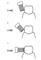
ブラシ角とは、歯軸(歯の頭と根に沿った軸)に対するブラシの当たり角である。図11の(A)がブラシ角=15度の状態、(B)がブラシ角=45度の状態、(C)がブラシ角=90度の状態を示している。歯周ポケットや歯間から食物残渣や歯垢を効果的に掻き出すには、ブラシの毛先が歯周ポケットや歯間に入り込むようにブラシを動かすとよい。したがって、ブラシ角は35度~55度の範囲が好ましい。
ブラシ角は、たとえば、z方向の加速度成分Azから推定可能である。図12に示すように、ブラシ角が約90度の場合はAzはほとんど0を示し、ブラシ角が小さくなるほどAzの値が大きくなる、というようにブラシ角に応じてAzの値が有意に変化するからである。なお、ブラシ角に応じてx方向の加速度成分Axも変化するため、Azの代わりにAxからブラシ角を推定したり、AxとAzの両方(AxとAzの合成ベクトルの方向)からブラシ角を推定することも好ましい。ブラシ角は連続量で算出してもよいし、「35度未満」「35度~55度」「55度以上」のような大まかな推定でもよい。
(ブラシ圧の検知)
図4のS50において、CPU120は、加速度センサ15の出力に基づいてブラシ圧を推定(検出)し、現在のブラッシング部位(図10の例では下顎左頬側)のブラシ圧の値を更新する。このとき、CPU120はメモリ121に記憶されているブラシ圧の値と今回の検出値とから、ブラシ圧の平均値を算出して記録することが好ましい。
図4のS50において、CPU120は、加速度センサ15の出力に基づいてブラシ圧を推定(検出)し、現在のブラッシング部位(図10の例では下顎左頬側)のブラシ圧の値を更新する。このとき、CPU120はメモリ121に記憶されているブラシ圧の値と今回の検出値とから、ブラシ圧の平均値を算出して記録することが好ましい。
ブラシ圧が低すぎると歯垢除去力が低下し、逆に高すぎるとブラシ寿命の低下や歯肉への負担増などの問題が生じる可能性がある。電動歯ブラシ1のブラシ圧は普通の歯ブラシの場合よりも低くてよいことから、電動歯ブラシ1を使いはじめたほとんどの人はブラシ圧超過の傾向にあるといわれている。ブラシ圧の最適値は100g~200g程度である。
本実施の形態に係るブラシ圧の推定の詳細は後述する。
(ブラッシング結果の評価・出力)
CPU120は、図4のS55またはS60においてメモリ121に記録されたブラッシング情報に基づいて、部位ごとのブラッシング結果を評価し、その評価結果を表示器110(ディスプレイ111)に出力する。
(ブラッシング結果の評価・出力)
CPU120は、図4のS55またはS60においてメモリ121に記録されたブラッシング情報に基づいて、部位ごとのブラッシング結果を評価し、その評価結果を表示器110(ディスプレイ111)に出力する。
図13は、ブラッシング時間の評価結果の出力例である。CPU120は、メモリ121から各部位のブラッシング時間を読み込み、たとえば、7秒未満を「不足」、7秒~15秒を「良好」、15秒超を「過剰」と評価する。その評価結果は表示器110に送信される。表示器110のディスプレイ111には歯列が描画されており、その歯列中の該当部位が評価結果に応じた色(「不足」は白色、「良好」は黄色、「過剰」は赤色など)で点灯される。このような表示を確認することで、使用者は歯列中のどの部位のブラッシングが不足しているか(あるいは過剰であったか)を直感的に把握できる。
図14は、ブラシ角の評価結果の出力例である。たとえば、「35度未満」、「35度~55度」、「55度以上」の三段階で評価され、歯列中の各部位が評価結果に応じた色で点灯する。適切でないブラシ角でブラッシングを行った場合、最適なブラシ角に比べて歯垢除去力が劣るため、所期のブラッシング効果が得られなかったり、ブラッシングに時間がかかったりする可能性がある。図14のように部位別にブラシ角の評価を出力すれば、使用者に対して正しいブラシ角によるブラッシングを意識させることができる。
図15は、ブラシ圧の評価結果の出力例である。たとえば、100g未満は「不足」、100g~200gは「良好」、200g超は「過大」と評価され、歯列中の各部位が評価結果に応じた色で点灯する。上述のようにブラシ圧が適切でないと、歯垢除去力の低下、ブラシ寿命の低下、歯肉への負担増などの問題が生じる可能性がある。とはいえ、使用者にとっては、どれくらいの力を加えたときに最適なブラシ圧なのかを理解するのは難しい。その点、図15のように部位別にブラシ圧の評価を出力すれば、使用者に対して適切なブラシ圧を教示できるとともに、正しいブラシ圧によるブラッシングを意識させることができる。
図16は、ブラッシング指標の評価結果の出力例である。ブラッシング指標とは、複数の評価項目(ブラッシング時間、ブラシ角、ブラシ圧)を総合的に評価するための指標であり、ブラッシングの達成度を表すものである。ブラッシング指標の算出式はどのように定義してもよい。本実施形態では、ブラッシング時間とブラシ圧をそれぞれ35点満点とし、ブラシ角を30点満点として、それらの値の合計(100点満点)をブラッシング指標として用いる。そして、ブラッシング指標(点数)を、「優」、「良」、「不可」の3段階で評価する。ここでは、ブラッシング指標の80点以上を「優」、60点~80点を「良」、60点未満を「不可」と評価している。
図16の左側にはブラッシング前の初期状態が示されて、右側にはブラッシング後の評価が、模式的に示される顎の歯列の各部位と関連付けて示される。このような総合評価を出力することで、使用者に対して、ブラッシングに関するより有益な指針を与えることができる。
以上述べたように、加速度センサ15の出力を利用することにより、高精度に電動歯ブラシ1の姿勢、および、ブラッシング部位の同定が可能となる。したがって、細かい区分(部位)でブラッシング結果を評価でき、有用かつ信頼性の高い評価指針を使用者に提供することが可能となる。しかも加速度センサ15は小型ゆえ、電動歯ブラシ1本体への組み込みも容易であるという利点もある。
なお、図13~図16の評価結果は、ディスプレイ111上に同時に表示してもよいし、順番に表示してもよい。後者の場合、表示の切替えは自動で行われてもよいし、使用者のボタン操作により行われてもよい。
また上記実施形態では、電動歯ブラシ1の電源がオフになると自動的に結果が表示される。しかし、表示器110の設置場所とは異なる場所で歯磨きが行われることも想定されるため、たとえば、使用者が表示器110または歯ブラシ本体2に設けられたボタンを押すと、歯ブラシ本体2から表示器110にブラッシング情報が送信され、表示器110に結果が表示されるような機能を設けることも好ましい。
メモリ121に蓄積されたブラッシング情報や評価結果を印刷できるとよい。たとえば充電器や表示器にプリンタ(図示せず)を搭載してもよいし、歯ブラシ本体や充電器や表示器から外部のプリンタに印刷データを送信できるようにしてもよい。またブラッシング情報や評価結果のデータを無線通信もしくは有線通信により図示しない外部機器(パーソナルコンピュータ、携帯電話、PDA(Portable Digital Assistant)など)に転送する機能も好ましい。また歯ブラシ本体、充電器、表示器などにメモリカードスロット(図示せず)を設け、ブラッシング情報や評価結果のデータを外部メモリカードに記録できるようにしてもよい。
また、ブラッシング時間、ブラシ角、ブラシ圧の最適値(目標値)を部位ごとに異なる値を設定できるようにしてもよい。たとえば、臼歯の歯面(側面)では、ブラシの毛先で歯周ポケットや歯間から食物残渣や歯垢を効果的に掻き出すために、35度~55度のブラシ角が好ましいが、歯面が比較的大きい前歯ではそれよりも大きい角度(たとえば55度~90度)が好ましい。また臼歯の噛み合わせ面に対しては、ブラシ角は約0度がよい。さらに、刷掃効果の観点からではなく、歯肉などの組織にダメージを与えることを避けるという観点から、最適なブラッシング時間、ブラシ角、ブラシ圧を決定することもできる。このように部位ごとに最適値を設定し、評価を行なえば、より有用かつ信頼性の高い評価指針の提供が可能となる。
(ブラシ圧の推定)
電動歯ブラシ1では、モータ10に同一の駆動信号が与えられるとしても、モータ10への負荷に応じて、すなわちブラシ圧に応じて振動数が変動することに着目して、ブラシ圧が推定される。ブラシ圧の増大とともに振動数は低下し、ブラシ圧が低いほど振動数は大きくなる。
電動歯ブラシ1では、モータ10に同一の駆動信号が与えられるとしても、モータ10への負荷に応じて、すなわちブラシ圧に応じて振動数が変動することに着目して、ブラシ圧が推定される。ブラシ圧の増大とともに振動数は低下し、ブラシ圧が低いほど振動数は大きくなる。
図4のS50では、ブラシ圧は、加速度センサ15から出力される電圧信号であるAx、AyおよびAzのいずれかを用いて検知(推定)される。
図17には、実施の形態に係るブラシ圧推定の為の機能構成が示される。図17の各部は、CPU120が実行を制御するプログラムと回路の組合わせにより実現される。これらプログラムは、メモリ121の所定領域に予め格納される。CPU120により、メモリ121からプログラムが読出され、読出されたプログラムの命令コードを実行することにより、各部の機能が実現される。
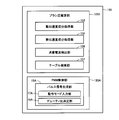
図17を参照して、CPU120は、ブラシ圧を推定するためのブラシ圧推定部1201およびモータ10をPWM制御に従って駆動するためのPWM制御部120Aを備える。
ブラシ圧推定部1201は、加速度センサ15の出力信号のうち、電動歯ブラシ1の動加速度成分および静加速度成分の信号を処理する動加速度成分処理部153および静加速度成分処理部155、モータ10の消費電流(供給電流)を指す電流検出部104の出力信号を入力し、入力信号に基づきモータ10の消費電流を検出する消費電流検出部156、メモリ121のテーブルTB1を検索し、検索結果を出力するテーブル検索部157を含む。
PWM制御部120Aは、モータ10の駆動を制御するためのパルス信号を生成するパルス信号生成部16Aを含む。パルス信号生成部16Aは、図示のないパルス信号発生回路を用いてパルス信号を生成する。パルス信号生成部16Aは、使用者がスイッチSを操作することにより指示した動作モードを入力する動作モード入力部17A、および入力した動作モードに基づきパルス信号のデューティ比を決定するデューティ比決定部18Aを有する。パルス信号生成部16Aは、決定されたデューティ比を有するパルス信号を生成して出力する。出力されるパルス信号は駆動信号としてモータ10に与えられる。
図18には、加速度センサ15とその周辺回路が概略的に示される。図18を参照して、加速度センサ15の出力段にはフィルタ部103が接続される。フィルタ部103は、加速度センサ15からの出力信号を入力し、所定周波数帯域の信号のみを通過させるBPF(Band Pass Filter)151と、BPF151の出力段に並列接続される、HPF(High Pass Filter)152およびLPF(Low Pass Filter)154とを有する。HPF152の出力段には動加速度成分処理部153が接続され、LPF154の出力段には静加速度成分処理部155が接続される。
HPF152は、BPF151からの入力信号のうち所定の遮断周波数(たとえば、90Hz)以上の周波数の信号だけを通過させて、出力する。LPF154は、BPF151からの入力信号のうち所定の遮断周波数(たとえば数Hz)以下の周波数の信号だけを通過させ、出力する。
動加速度成分処理部153は、HPF152から出力される信号10Dを入力し処理することにより、モータ10の回転動作に伴う電動歯ブラシ1本体の振動数を検出する。HPF152から出力される信号10Dは、モータ10の回転(振動)に起因した振動数(たとえば、100Hz~300Hzの周波数帯域)の信号に相当する。静加速度成分処理部155は、LPF154から出力される信号10Sを入力し処理する。この入力信号10Sは、歯磨き中の使用者が電動歯ブラシ1をひねるなどのブラシの姿勢を変える動作に起因する振動数(たとえば、数Hzの周波数帯域)の信号に相当する。したがって、信号10Sは、電動歯ブラシ1本体の姿勢情報成分の信号に相当する。
(振動数の検出)
図19の(A)には、図18のBPF151の出力信号の波形の一例が時間経過に従って示される。図19の(A)においては、数Hz以下の低周波成分である信号10S(図中は、太い実線で示す)に、100Hz~300Hzの高周波成分であるモータ10の回転動作に起因した振動成分の信号10D(図中は、細い実線で示す)が重畳しているが、上述のフィルタ部103を通過させることにより信号10Dと10Sを分離して出力することができる。図19の(B)においては、図19の(A)のある時間帯の信号10Dが抽出されて拡大して示される。
図19の(A)には、図18のBPF151の出力信号の波形の一例が時間経過に従って示される。図19の(A)においては、数Hz以下の低周波成分である信号10S(図中は、太い実線で示す)に、100Hz~300Hzの高周波成分であるモータ10の回転動作に起因した振動成分の信号10D(図中は、細い実線で示す)が重畳しているが、上述のフィルタ部103を通過させることにより信号10Dと10Sを分離して出力することができる。図19の(B)においては、図19の(A)のある時間帯の信号10Dが抽出されて拡大して示される。
図19の(B)を参照して、振動数を検出する手順を説明する。動加速度成分処理部153は、信号10Dを入力し、入力した信号10Dの波形について、所定周期T(以下、サンプリング周期Tという)毎に波形の傾きを検出する。この傾きは、波形を微分処理などすることにより検出することができる。動加速度成分処理部153は、サンプリング周期T毎に、信号10Dが示す波形の傾き(正の傾き、または負の傾き)を検出し、正の傾きが連続する期間の長さまたは負の傾きが連続する期間の長さ、および正の傾きから負の傾きへ(または負の傾きから正の傾きへ)の切換わるタイミングを検出する。検出結果に基づき信号10Dの周波数、すなわち電動歯ブラシ1の振動数を検出する。検出された振動数は、テーブル検索部157に出力される。
振動数の検出方法は、図19の(B)に示される方法に限定されない。たとえば、信号10Dの波形を微分処理することによって極値(極大値と極小値)を検出し、所定時間期間において検出される極大値と極小値の個数に基づき、信号10Dの周波数、すなわち振動数を検出するようにしてもよい。
(振動数に基づくブラシ圧の検出)
図20のグラフは、振動数と負荷(ここでは、ブラシ圧)の相関関係を示す。図20のグラフは発明者の実験結果に基づくデータを指す。グラフでは、縦軸に振動数(Hz)をとり、横軸にはモータ10にかかる負荷(グラム:g)の大きさをとる。
図20のグラフは、振動数と負荷(ここでは、ブラシ圧)の相関関係を示す。図20のグラフは発明者の実験結果に基づくデータを指す。グラフでは、縦軸に振動数(Hz)をとり、横軸にはモータ10にかかる負荷(グラム:g)の大きさをとる。
モータ10は、PWM制御部120Aから同一の駆動信号が与えられた状態において、無負荷(負荷が無い)のときに最も速い速度で回転し、負荷が増加するに従って回転速度は低下する。
具体的には、無負荷状態では、モータ10の回転による電動歯ブラシ1の振動数は最大振動数V1を指示し、ブラシ210が歯に押し当てられるなどして、ブラシ210全体に荷重がかかるようになると、ブラシ圧が増加する。これに伴いモータ10にかかる負荷は増加し、モータ10の回転速度は低下し、振動数は減少する。たとえば、ブラシ圧が100~200g(適圧)の場合には、モータ10の振動数は適圧時振動数V2~V3の範囲で検出される。さらに、ブラシ210が歯に強く押し当てられるなどして、たとえば500gの過大な荷重がブラシ210全体にかかると、モータ10に過大の負荷がかかった状態となり、振動数は、過大圧時振動数V4~0の範囲で推移する。
図20の相関関係に従えば、信号10Dの周波数に基づいて、すなわち振動数に基づいてブラシ圧を一意に決定(検出)することができる。
本実施の形態では、図20のグラフの特性で示される振動数のデータと、対応するブラシ圧のデータは、関連付けられてテーブルTB1に予め格納される。テーブル検索部157は、動加速度成分処理部153から出力された振動数に基づき、当該テーブルTB1を検索し、検索結果に基づき、当該振動数に対応のブラシ圧をテーブルTB1から読出す。これにより、ブラシ圧推定部1201は、ブラシ圧を検出(推定)することができる。
(ブラシ圧推定の概略処理)
図21には、本実施の形態によるブラシ圧検知(推定)処理の概略フローチャートが示される。
図21には、本実施の形態によるブラシ圧検知(推定)処理の概略フローチャートが示される。
図21を参照して、ブラシ圧推定部1201は、加速度センサ15の出力信号をフィルタ部103を介して入力する(ステップSS(以下、単にSSと称する)3)。動加速度成分処理部153は、上述の(振動数の検出)の手順に従い振動数を検出する(SS5)。続いて、テーブル検索部157は、ステップSS5において検出された振動数に基づき、上述の(振動数に基づくブラシ圧の検出)の手順に従って、テーブルを検索し(SS7)、ブラシ圧を検出する(SS9)。これにより、ブラシ圧が決定(推定)される。
(ブラシ圧推定の他の方法)
ブラシ圧推定部1201は、上述した手順ではモータ10の振動数のみに基づきブラシ圧を推定したが、モータ10への供給電流に基づき振動数を検出するようしてもよい。
ブラシ圧推定部1201は、上述した手順ではモータ10の振動数のみに基づきブラシ圧を推定したが、モータ10への供給電流に基づき振動数を検出するようしてもよい。
図22には、本実施の形態に係るモータ10の負荷特性のグラフが示される。図22のグラフの縦軸にはモータ10の回転数(rpm)とモータ10への供給電流(すなわちモータ10の消費電流)(単位:A)が示される。横軸には、モータ10にかかるトルク(負荷)が示される。このトルクは、前述したブラシ圧に相当する。図22の直線SAは、モータ10への供給電流は、トルク(負荷)が大きくなるほど増大するという理想的な特性を表わしている。直線RAは、モータ10の回転数は、トルク(負荷)が増加するほど、減少することの特性を表す。ここでは、直線SAが指す供給電流のデータと、対応するトルクのデータとは実験により予め検出されて、関連付けされてテーブルTB2に格納される。
モータ10への供給電流は、消費電流検出部156が、電流検出部104を用いて検出する。電流検出部104は、モータ10の駆動信号の入力段に接続された抵抗素子に相当する。消費電流検出部156は、当該抵抗素子にかかる電圧を測り、測定された電圧を抵抗素子の抵抗値で除することにより、モータ10に供給される電流を検出する。なお、抵抗値を用いた検出に代替して、電流センサを用いた検出であってもよい。
モータ10に適用される直流モータは、直線SAに示すように、トルクが0から増加するにつれてモータ10への供給電流は増加するが、供給電流の増加につれてモータ10は発熱する。つまり、トルクが所定値TH(>0)を指示するとき、モータ10には値SA1の電流が供給されるとすれば、トルクが所定値THを超えると、モータ10への供給電流(>SA1)のうち発熱のために消費される電流が多くなり、直線SAは、図22のような理想的な相関関係を示さなくなる。
したがって、トルクが比較的小さい期間は、たとえばトルクが0~THに対応する電流の供給期間は、直線SAが示すモータ10の供給電流とトルクの関係に従えば、モータ10の供給電流に基づきブラシ圧を検出することが可能である。トルクが所定値THよりも大きくなるような期間においては、すなわち電流値SA1よりも大きい電流が供給される期間においては、消費電流ではなく、上述したように振動数に基づきテーブルTB1を検索してブラシ圧を検出する。なお、電流値SA1は実験により予め検出されて、メモリ121に格納される。
動作において、ブラシ圧推定部1201は、消費電流検出部156が検出する電流値と、メモリ121から読出す電流値SA1とを比較し、比較結果に基づき、テーブル検索部157を制御する。
つまり、比較結果に基づき、電流値SA1以下の電流が供給されると判定する期間においては、テーブル検索部157を、消費電流検出部156が検出するモータ10の消費電流値に基づき、テーブルTB2を検索するように制御する。テーブル検索部157は、検索結果に基づき、対応するトルク(ブラシ圧)をテーブルTB2から読出す。一方、比較結果に基づき、電流値SA1よりも大きい電流が供給されると判定する期間においては、テーブル検索部157を、上述したように振動数に基づきテーブルTB1を検索するように制御する。テーブル検索部157は、検索結果に基づき、対応するブラシ圧をテーブルTB1から読出す。これにより、ブラシ圧推定部1201は、モータ10の消費電流および振動数の一方、または両方に基づきブラシ圧を精度良く推定することができる。
(モータ10への供給電力の補償)
発明者は、ブラシ圧をより正確に推定するためには、振動数の検出精度を上げる必要があるとの動機付けのもと、モータ10の回転数すなわち振動数が低下する要因には、負荷の増加(ブラシ圧増加)および電池寿命が含まれるとの知見を得た。
発明者は、ブラシ圧をより正確に推定するためには、振動数の検出精度を上げる必要があるとの動機付けのもと、モータ10の回転数すなわち振動数が低下する要因には、負荷の増加(ブラシ圧増加)および電池寿命が含まれるとの知見を得た。
そこで、本実施の形態では、充電池13からモータ10に供給される電力を一定とするように補償する。これにより、電池寿命に起因する振動数の低下要因を排除することができる。
図23には、充電池13の出力電圧の経時変化が模式的に示される。ここでは、出力電圧は、充電池13の電池残量を指す。図23のグラフは実験により得られた特性を示し、縦軸には、電池の出力電圧(単位:V)がとられ、横軸には、経過時間tがとられている。
電動歯ブラシ1には、充電池13として一般的にニッケル水素電池が用いられる。充電池13の定格出力は、たとえば2.4Vであるとする。充電済みの充電池13の使用開始時は、出力電圧は定格出力(2.4V)を維持できるけれども、使用時間が経過するにつれ、出力電圧は低下する。余分な放電のない理想的な電池を想定した場合、図22の実線で示されるように、出力電圧は、電池の寿命が尽きるとき(時間t1)まで定格電圧(2.4V)を維持し、時間t1になったときに、出力電圧が0となる。しかしながら、一般的な電池は、このような理想的特性を示さない。つまり充電池13は、図22の破線で示されるように、徐々に定格電圧(2.4V)を維持することができなくなり、使用開始時からの経過時間が時間t2(<t1)になったとき、出力電圧は2.0Vとなり以降急激に低下する。充電池13の出力電圧が2.0V以下になると、電動歯ブラシ1は十分な動作能力を奏しえなくなり、十分な振動数を得られない。
そこで、CPU120は、図17のPWM制御部120Aに代替して、図24のPWM制御部120Bを備える。図24を参照して、PWM制御部120Bは、モータ10の駆動を制御するためのパルス信号を生成するパルス信号生成部16Bを含む。パルス信号生成部16Bは、図示のないパルス信号発生回路を用いてパルス信号を生成する。パルス信号生成部16Bは、使用者がスイッチSを操作することにより指示した動作モードを入力する動作モード入力部17A、電圧モニタ102の検出信号を入力し、入力した検出信号に基づき充電池13の出力電圧を検知する電池電圧入力部19A、および動作モードと充電池13の出力電圧とに基づき、パルス信号のデューティ比を決定するデューティ比決定部18Bを有する。パルス信号生成部16Bは、決定されたデューティ比を有するパルス信号を生成して出力する。パルス信号は、駆動信号としてモータ10に与えられる。
図25を参照して、PWM制御に用いられるパルス信号のデューティ比の変更について説明する。図25には横軸に時間がとられ、縦軸にパルス信号のON/OFFレベル(電圧)がとられている。モータ10への供給電力は、図25の斜線部に示すように、パルス信号のON期間の長さとONに対応する電圧との積(=電圧×時間)で決定される。そこで、本実施の形態では、デューティ比決定部18Bは、モータ10への供給電力(=電圧×時間)を一定とするようにパルス信号のデューティ比を変更する。ここで、デューティ比とは、パルス信号の1周期の長さを100%とした場合に、1周期の長さに対する電圧レベルがONである期間の長さを指す。デューティ比を変更するにより、充電池13の出力電圧が下がっても、モータ10に供給される電力を一定とすることができて、振動数を維持することができる。
図26には、デューティ比を変更するためにデューティ比決定部18Bにより参照されるテーブルTB3の一例が示される。テーブルTB3には、電動歯ブラシ1の動作モードの種類MDと充電池13の出力電圧値BVの組のそれぞれに対応して、モータ10に供給される電力を一定とするためのデューティ比DRが格納される。テーブルTB3のデータは、予め実験により取得される。ここでは、出力電圧値BVとして2.4V,2.2Vおよび2Vが格納され、動作モードの種類MDとしては高速に振動する“高速”モード、それよりも低い速度で振動する“中速”モードおよびさらに低い速度で振動する“低速”モードの3種類が格納される。なお、格納される出力電圧値BVの種類および動作モードの種類MDの数は、これに限定されるものではない。
動作において、動作モード入力部17Aは、使用者がスイッチSを操作することにより指定している動作モードの種類を入力し、電池電圧入力部19Aは充電池13の出力電圧を検知する。デューティ比決定部18Bは、入力された動作モードの種類と、検知された出力電圧との組に基づき、図26のテーブルTB3を検索する。検索結果に基づき、当該組に対応するデューティ比DRを、テーブルTB3から読出す。パルス信号生成部16Bは、読出されたデューティ比DRを有するパルス信号を生成して出力する。出力されるパルス信号は、駆動信号としてモータ10に与えられる。
このようにデューティ比DRを変更することにより、充電池13の出力電圧(電池残量)低下という振動数の低下要因を排除できて、正確なブラシ圧の検出が可能となる。
(ブラシ圧の検出)
前述したモータ10への供給電力の補償を行なわずとも、振動数に基づき、ブラシ圧を正確に検出する例を示す。
前述したモータ10への供給電力の補償を行なわずとも、振動数に基づき、ブラシ圧を正確に検出する例を示す。
図27には、ブラシ圧の検索機能を備えるブラシ圧推定部1202の機能構成が示される。図17のブラシ圧推定部1201に代替してブラシ圧推定部1202を用いてもよい。ブラシ圧推定部1202は、動加速度成分処理部153、静加速度成分処理部155および、ブラシ圧検索部159を含む差分振動数検出部158を備える。ブラシ圧推定部1202の差分振動数検出部158を除く他の構成は、ブラシ圧推定部1201と同様であるから説明は略す。
差分振動数検出部158は、動加速度成分処理部153から出力される振動数(Hz)を入力し、入力した振動数と無負荷時の振動数との差分を検出する。そして、検出した差分に基づきブラシ圧を検出する。これにより、ブラシ圧が推定される。
ブラシ圧検出のために、図28および図29のテーブルTB4およびTB5が、ブラシ圧検索部159により検索される。図28のテーブルTB4には、電動歯ブラシ1の動作モードMDの種類と、充電池13の出力電圧BVとの組のそれぞれに対応して、モータ10にかかる負荷が0(無負荷)のときの振動数(Hz)DVが予め格納される。テーブルTB4に格納される動作モードMDの種類数および出力電圧BVの種類は、これに限定されない。
図29のテーブルTB5には、テーブルTB4から読出された振動数DVと、動加速度成分処理部153が検出する振動数との差分DFと、差分DFのそれぞれに対応してブラシ圧PRが予め格納される。テーブルTB4とTB5のデータは、実験により予め検出される。
電動歯ブラシ1が電源ONされて実行される図4の初期化処理(S5)では、モータ10は無負荷状態である。ステップS5において、差分振動数検出部158は、電圧モニタ102から充電池13の出力電圧値を指す信号を入力する。
差分振動数検出部158のブラシ圧検索部159は、スイッチSから入力する使用者が指示する動作モードの種類と、電圧モニタ102からの入力信号が指す電圧値の組に基づき、テーブルTB4を検索する。検索結果に基づき、当該電圧値と動作モードの組に対応する振動数DVを、テーブルTB4から読出す。差分振動数検出部158は、テーブルTB4から読出された無負荷時の振動数DVをメモリ121の所定領域に記憶する。
初期化処理(ステップS5)が終了すると、ブラッシングによりブラシ圧が生じて、モータ10のトルクは増加する。これに伴い、動加速度成分処理部153が検出するモータ10の振動数も増加する。
初期化処理終了後のブラシ圧検知処理(S50)では、差分振動数検出部158は、動加速度成分処理部153が順次に検出する振動数と、メモリ121の所定領域から読出した振動数DVとの差分を検出(算出)する。そして、ブラシ圧検索部159は、検出された差分に基づき、メモリ121のテーブルTB5を検索する。検索結果に基づき、検出した差分に一致する差分DFに対応するブラシ圧PRをテーブルTB5から読出す。これにより、ブラシ圧(ブラシ圧PR)が検出(推定)される。
このように充電池13の出力電圧(電池残量)に応じた無負荷時の振動数と、負荷がかかっている場合の振動数の差分は、負荷すなわちブラシ圧の大きさに相当することから、上述のようにモータ10の無負荷時の振動数と、負荷が有るときの振動数との差分に基づき、負荷の大きさすなわちブラシ圧を推定することができる。
(ブラシ圧の報知)
図30では、検知されたブラシ圧を報知するための表示部16が一体的に取り付けられた電動歯ブラシ1の外観が示される。
図30では、検知されたブラシ圧を報知するための表示部16が一体的に取り付けられた電動歯ブラシ1の外観が示される。
ブラシ圧は、図3の表示器110で表示することもできるが、表示部16により表示することもできる。表示部16は、LED(Light Emitting Diode)などの発光部からなり、ブラッシング時に使用者が確認し易いように本体2の端に設けられる。表示部16は、略円筒状の本体2のハウジング周囲を一周するように配置される。端部に配置すると、鏡に映して確認することも可能である。なお、表示部16は、本体2のブラシ210側の端に設けてもよい。
表示態様として、検出されるブラシ圧に応じて、表示部16のLEDの点灯状態を変化させる。たとえば、ブラシ圧が高いと評価されるほど高速にLEDを点滅させ、またはLEDの輝度を上げる。または、ブラシ圧が高いと評価されると赤色で点灯し、低いと評価されると緑色で点灯するようにしてもよい。
検出された振動数は、表示器110または表示部16を介して表示することで報知してもよい。
ブラシ圧および振動数の報知の態様は、表示部16を用いたものに特定されず、音や音声を用いた出力であってもよい。
なお、駆動源としては、直流モータ10でなくても良い。たとえば、ソレノイド、圧電素子、超音波振動子、人工筋肉などを利用したアクチュエータであってもよい。
このように、今回開示した上記実施の形態はすべての点で例示であって、制限的なものではない。本発明の技術的範囲は請求の範囲によって画定され、また請求の範囲の記載と均等の意味および範囲内でのすべての変更を含むものである。
1 電動歯ブラシ、15 加速度センサ、16A,16B パルス信号生成部、17A 動作モード入力部、18A,18B デューティ比決定部、19A 電池電圧入力部、103 フィルタ部、120 CPU、120A,120B PWM制御部、153 動加速度成分処理部、155 静加速度成分処理部、156 消費電流検出部、157 テーブル検索部、158 差分振動数検出部、159 ブラシ圧検索部、1201,1202 ブラシ圧推定部、TB1~TB5 テーブル。
Claims (8)
- ケア部材を用いて口腔をケアする口腔ケア装置(1)であって、
加速度センサ(15)と、
前記ケア部材を振動させるための駆動部(10)と、
前記ケア部材の振動数を検出するための振動数検出部と、を備え、
前記振動数検出部は、前記加速度センサの出力信号の波形に基づき、前記振動数を検出する、口腔ケア装置。 - 前記振動数検出部が検出した前記振動数に基づき、前記ケア部材に作用する荷重を指す部材圧を検出する、請求項1に記載の口腔ケア装置。
- 前記駆動部はモータであり、
前記振動数検出部は、
無負荷時の前記モータの回転による前記振動数と、前記振動数検出部が検出する前記振動数との差分に基づき、前記部材圧を検出する、請求項2に記載の口腔ケア装置。 - 前記駆動部はモータであり、
前記モータの消費電流を検出する消費電流検出部、をさらに備え、
前記振動数検出部は、さらに、前記消費電流検出部が検出する前記消費電流に基づき、前記振動数を検出する、請求項1に記載の口腔ケア装置。 - 前記口腔ケア装置の各部に電力を供給する電源(13)と、
前記電源が出力する電力を検出する電力検出部と、
前記電力検出部が検出する前記電力の値に基づき、前記駆動部に供給される電力を補う電力補償部と、をさらに備える、請求項1に記載の口腔ケア装置。 - 前記電力補償部は、
前記電力検出部が検出する前記電力の値に基づき、駆動するために前記駆動部に与えられるパルス信号のデューティ比を変更する、請求項5に記載の口腔ケア装置。 - 検出される前記部材圧を報知する、請求項2に記載の口腔ケア装置。
- 検出される前記振動数を表示する、請求項1に記載の口腔ケア装置。
Priority Applications (3)
| Application Number | Priority Date | Filing Date | Title |
|---|---|---|---|
| CN201180007937.6A CN102740732B (zh) | 2010-02-02 | 2011-01-21 | 口腔护理装置 |
| EP11739634.1A EP2532270B1 (en) | 2010-02-02 | 2011-01-21 | Oral care apparatus |
| US13/491,032 US8863343B2 (en) | 2010-02-02 | 2012-06-07 | Oral care apparatus |
Applications Claiming Priority (2)
| Application Number | Priority Date | Filing Date | Title |
|---|---|---|---|
| JP2010021097A JP5526825B2 (ja) | 2010-02-02 | 2010-02-02 | 口腔ケア装置 |
| JP2010-021097 | 2010-02-02 |
Related Child Applications (1)
| Application Number | Title | Priority Date | Filing Date |
|---|---|---|---|
| US13/491,032 Continuation US8863343B2 (en) | 2010-02-02 | 2012-06-07 | Oral care apparatus |
Publications (1)
| Publication Number | Publication Date |
|---|---|
| WO2011096285A1 true WO2011096285A1 (ja) | 2011-08-11 |
Family
ID=44355287
Family Applications (1)
| Application Number | Title | Priority Date | Filing Date |
|---|---|---|---|
| PCT/JP2011/051095 WO2011096285A1 (ja) | 2010-02-02 | 2011-01-21 | 口腔ケア装置 |
Country Status (5)
| Country | Link |
|---|---|
| US (1) | US8863343B2 (ja) |
| EP (1) | EP2532270B1 (ja) |
| JP (1) | JP5526825B2 (ja) |
| CN (1) | CN102740732B (ja) |
| WO (1) | WO2011096285A1 (ja) |
Cited By (5)
| Publication number | Priority date | Publication date | Assignee | Title |
|---|---|---|---|---|
| WO2013027462A1 (ja) * | 2011-08-24 | 2013-02-28 | オムロンヘルスケア株式会社 | 歯の歯垢除去に適用される口腔ケア装置 |
| JP2015527162A (ja) * | 2012-09-07 | 2015-09-17 | コーニンクレッカ フィリップス エヌ ヴェ | ホール効果センサを用いる感圧機能を有する共振駆動電動歯ブラシ |
| CN107432775A (zh) * | 2016-05-27 | 2017-12-05 | 深圳减字科技有限公司 | 一种电动牙刷的振动强度控制方法及系统 |
| CN108594640A (zh) * | 2018-03-28 | 2018-09-28 | 郭剑东 | 一种智能电动变频牙刷、控制系统及方法 |
| CN111212585A (zh) * | 2017-10-13 | 2020-05-29 | 皇家飞利浦有限公司 | 具有高压指示器的个人护理设备 |
Families Citing this family (45)
| Publication number | Priority date | Publication date | Assignee | Title |
|---|---|---|---|---|
| CN103906480B (zh) * | 2011-10-24 | 2016-07-06 | 皇家飞利浦有限公司 | 用于确定电动牙刷刷头在嘴中的幅度的系统 |
| US9223903B2 (en) | 2012-04-19 | 2015-12-29 | International Business Machines Corporation | Analyzing data from a sensor-enabled device |
| RU2654771C2 (ru) * | 2012-12-21 | 2018-05-22 | Конинклейке Филипс Н.В. | Адаптивная система для изменения пользовательского процесса чистки зубов |
| US20130132388A1 (en) | 2013-01-22 | 2013-05-23 | Ashtel Studios, Inc. | Apparatus for capturing brushing habits |
| US9498053B2 (en) * | 2013-01-22 | 2016-11-22 | Ashtel Studios, Inc. | Apparatus for capturing brushing habits |
| US9060595B2 (en) * | 2013-06-13 | 2015-06-23 | L'oreal | Performance regulation for a personal care appliance |
| WO2014202438A1 (de) | 2013-06-19 | 2014-12-24 | Benjamin Ohmer | Verfahren zur bestimmung von bewegungsmustern bei einer zahnbehandlung |
| US10349733B2 (en) * | 2013-06-19 | 2019-07-16 | Kolibree | Toothbrush system with sensors for a dental hygiene monitoring system |
| CN103565101A (zh) * | 2013-11-20 | 2014-02-12 | 江南大学 | 一种加速度和压力传感器在牙刷上的安装方法 |
| CN103565102A (zh) * | 2013-11-20 | 2014-02-12 | 江南大学 | 一种能判断刷牙动作和持续时间的牙刷 |
| CA2932133C (en) * | 2013-12-24 | 2018-07-24 | Braun Gmbh | Position detection of an oral care implement |
| US9041321B1 (en) * | 2014-06-30 | 2015-05-26 | Case-Mate, Inc. | PWM control of vibration motors for mobile electronic devices |
| US10201398B2 (en) | 2015-03-20 | 2019-02-12 | Kaltenbach & Voigt Gmbh | Dispensing material from a dental handpiece |
| CA2985287C (en) | 2015-05-13 | 2021-11-02 | Kolibree | Toothbrush system with magnetometer for dental hygiene monitoring |
| JP6599656B2 (ja) * | 2015-06-18 | 2019-10-30 | オムロンヘルスケア株式会社 | 電動歯ブラシ及びブラッシング部位推定方法 |
| WO2016205055A1 (en) | 2015-06-18 | 2016-12-22 | Colgate-Palmolive Company | Electric toothbrush device and method |
| CN104957877A (zh) * | 2015-07-30 | 2015-10-07 | 洛阳创知电子科技有限公司 | 一种智能牙刷 |
| EP3156001B1 (en) * | 2015-10-16 | 2019-01-09 | Braun GmbH | Personal hygiene device and method of controlling the personal hygiene device |
| WO2017109633A1 (en) | 2015-12-22 | 2017-06-29 | Koninklijke Philips N.V. | Systems, methods, and devices for providing guidance and feedback based on location and performance |
| RU2724672C2 (ru) * | 2016-01-26 | 2020-06-25 | Конинклейке Филипс Н.В. | Устройство обратной связи и способ ее предоставления для пользователей устройств для ухода за полостью рта, прикладывающих давление при использовании |
| CN108778052A (zh) * | 2016-02-25 | 2018-11-09 | 皇家飞利浦有限公司 | 用于通过反馈的手段实现最优口腔卫生的方法和系统 |
| EP3410891B1 (en) | 2016-03-14 | 2021-08-11 | Kolibree | Oral hygiene system with visual recognition for compliance monitoring |
| JP6706103B2 (ja) | 2016-03-15 | 2020-06-03 | オムロンヘルスケア株式会社 | グリップ部分とブラシ部分のとの間を強固に接続した電動歯ブラシ |
| JP6679355B2 (ja) | 2016-03-15 | 2020-04-15 | オムロンヘルスケア株式会社 | 照明リングを備えた電動歯ブラシ |
| CN106175961A (zh) * | 2016-08-05 | 2016-12-07 | 深圳易加仁技术有限公司 | 连接件及口腔清洁装置 |
| WO2018037318A1 (en) | 2016-08-22 | 2018-03-01 | Kolibree SAS | Oral hygiene system for compliance monitoring and tele-dentistry system |
| US11043141B2 (en) | 2016-11-14 | 2021-06-22 | Colgate-Palmolive Company | Oral care system and method |
| US11213120B2 (en) | 2016-11-14 | 2022-01-04 | Colgate-Palmolive Company | Oral care system and method |
| US10582764B2 (en) | 2016-11-14 | 2020-03-10 | Colgate-Palmolive Company | Oral care system and method |
| US10835028B2 (en) * | 2016-11-14 | 2020-11-17 | Colgate-Palmolive Company | Oral care system and method |
| US11361672B2 (en) | 2016-11-14 | 2022-06-14 | Colgate-Palmolive Company | Oral care system and method |
| JP7121006B2 (ja) * | 2016-12-01 | 2022-08-17 | コーニンクレッカ フィリップス エヌ ヴェ | 口腔洗浄装置の校正方法及びシステム |
| US10610008B2 (en) * | 2016-12-15 | 2020-04-07 | Water Pik, Inc. | Brushing device with illumination features |
| CN106723937A (zh) * | 2016-12-28 | 2017-05-31 | 北京小牙兽健康科技有限公司 | 刷牙系统及方法 |
| GB201713034D0 (en) * | 2017-08-14 | 2017-09-27 | Playbrush Ltd | Toothbrush coaching system |
| ES2795030T3 (es) * | 2017-09-22 | 2020-11-20 | Braun Gmbh | Dispositivo de higiene personal |
| WO2019137831A1 (en) | 2018-01-10 | 2019-07-18 | Koninklijke Philips N.V. | A light guiding unit |
| EP4327776A2 (en) | 2018-01-31 | 2024-02-28 | Quip NYC Inc. | A toothbrush system |
| CN108451155B (zh) * | 2018-04-13 | 2020-09-08 | 深圳市力博得科技有限公司 | 智能牙刷的控制电路、智能牙刷及刷牙行为的监控方法 |
| CN108903982B (zh) * | 2018-04-26 | 2020-07-21 | 北京奇禹科技有限公司 | 一种牙套式牙齿清洁方法 |
| GB201808555D0 (en) * | 2018-05-24 | 2018-07-11 | Playbrush Ltd | Electric toothbrush system |
| CN108852546B (zh) * | 2018-07-30 | 2021-03-12 | 广东小天才科技有限公司 | 一种基于压力检测控制刷牙强度的方法及电动牙刷 |
| DE102019120648A1 (de) * | 2018-08-02 | 2020-02-20 | Ranir, Llc | Drucksensorsystem und Verfahren für eine elektrische Zahnbürste |
| JP7303417B2 (ja) * | 2018-12-28 | 2023-07-05 | サンスター株式会社 | 口腔衛生装置及び口腔衛生支援システム |
| CN112674898B (zh) * | 2020-12-21 | 2021-08-31 | 深圳市力博得科技有限公司 | 基于压力调节振动频率的控制方法、控制系统及存储介质 |
Citations (6)
| Publication number | Priority date | Publication date | Assignee | Title |
|---|---|---|---|---|
| JPH10108734A (ja) | 1996-10-07 | 1998-04-28 | Lion Corp | 歯磨き圧指示器 |
| JP2005152217A (ja) | 2003-11-25 | 2005-06-16 | Sunstar Inc | ブラッシング方法学習用支援装置及びそれを用いた口腔内衛生装置 |
| WO2006137648A1 (en) * | 2005-06-20 | 2006-12-28 | Jin-Sang Hwang | Tooth brushing pattern analyzing/modifying device, method and system for interactively modifying tooth brushing behavior |
| WO2009113491A1 (ja) * | 2008-03-14 | 2009-09-17 | オムロンヘルスケア株式会社 | 電動歯ブラシ |
| WO2009148018A1 (ja) * | 2008-06-02 | 2009-12-10 | オムロンヘルスケア株式会社 | 電動歯ブラシ |
| WO2010106850A1 (ja) * | 2009-03-17 | 2010-09-23 | オムロンヘルスケア株式会社 | 電動歯ブラシ |
Family Cites Families (43)
| Publication number | Priority date | Publication date | Assignee | Title |
|---|---|---|---|---|
| US1803458A (en) * | 1928-03-08 | 1931-05-05 | Robert C Berry | Clutch |
| US3685080A (en) * | 1969-08-28 | 1972-08-22 | Huebner Otto | Mechanically powered toothbrush |
| US4591748A (en) * | 1983-04-11 | 1986-05-27 | Greer John W | Electronically powered apparatus for imparting vibratory forces on a tree |
| US4716614A (en) * | 1985-11-07 | 1988-01-05 | Jones Arthur R | Device for monitoring the process of toothbrushing |
| JPS63140963A (ja) * | 1986-12-02 | 1988-06-13 | Mitsubishi Electric Corp | 交流回転機の回転速度検出装置 |
| DE3911303C1 (ja) * | 1989-04-07 | 1990-08-23 | Braun Ag, 6000 Frankfurt, De | |
| GB2234037A (en) * | 1989-05-30 | 1991-01-23 | Kramatorsk Ind I | Unbalance vibrator |
| US5493747A (en) * | 1993-07-27 | 1996-02-27 | Matsushita Electric Works, Ltd. | Electric toothbrush |
| US5561881A (en) * | 1994-03-22 | 1996-10-08 | U.S. Philips Corporation | Electric toothbrush |
| DE29515288U1 (de) * | 1995-09-23 | 1995-11-23 | Rowenta Werke Gmbh | Elektrische Zahnbürste |
| US5850659A (en) * | 1996-03-26 | 1998-12-22 | The Smart Brush Corporation | Toothbrush with bendable head |
| US5749381A (en) * | 1996-03-26 | 1998-05-12 | Butler; C. P. | Toothbrush for implementing the bass brushing technique |
| DE19654319C1 (de) * | 1996-12-24 | 1998-08-06 | Rowenta Werke Gmbh | Elektrische Zahnbürste |
| US6564940B2 (en) * | 1998-09-30 | 2003-05-20 | The Procter & Gamble Company | Electric toothbrush |
| DE19916161B4 (de) * | 1999-04-11 | 2008-06-05 | Dürr Dental GmbH & Co. KG | Einrichtung zur Erzeugung hochfrequenter mechanischer Schwingungen für ein dentales Handstück |
| US6611780B2 (en) * | 1999-06-09 | 2003-08-26 | Koninklijke Philips Electronics N.V. | System for communicating operational data between an electric toothbrush and a separate control unit |
| DE29913406U1 (de) * | 1999-07-31 | 1999-11-25 | Rowenta Werke Gmbh | Zubehörträger für eine elektrische Zahnbürste |
| US6536068B1 (en) * | 1999-12-29 | 2003-03-25 | Gillette Canada Company | Toothbrushing technique monitoring |
| JP2002073990A (ja) * | 2000-06-15 | 2002-03-12 | Matsushita Electric Ind Co Ltd | 保険内容調整システム |
| DE10159395B4 (de) * | 2001-12-04 | 2010-11-11 | Braun Gmbh | Vorrichtung zur Zahnreinigung |
| GB0109444D0 (en) * | 2001-04-17 | 2001-06-06 | Unilever Plc | Toothbrush usage monitoring system |
| CN2506225Y (zh) * | 2001-04-27 | 2002-08-21 | 陈谭余 | 双杠杆传动电动牙刷 |
| KR20030025801A (ko) * | 2001-09-21 | 2003-03-29 | 로오젠스타즈가부시키가이샤 | 고속진동칫솔 |
| US6739012B2 (en) * | 2001-12-20 | 2004-05-25 | Koninklijke Philips Electronics N.V. | Power toothbrush with brushing pressure feedback |
| JP2008532619A (ja) * | 2005-03-09 | 2008-08-21 | ザ プロクター アンド ギャンブル カンパニー | センサー反応型電動歯ブラシ及びその使用法 |
| US7310844B1 (en) * | 2005-07-13 | 2007-12-25 | Rehco Llc | Toothbrush with manual powered movable brush head |
| US7691106B2 (en) * | 2005-09-23 | 2010-04-06 | Synvasive Technology, Inc. | Transverse acting surgical saw blade |
| US7464430B2 (en) * | 2006-01-03 | 2008-12-16 | Ehsan Filsouf | Electric toothbrush |
| DE102006004146A1 (de) * | 2006-01-27 | 2007-08-02 | Braun Gmbh | Elektrische Zahnbürste |
| US8758022B2 (en) * | 2006-02-16 | 2014-06-24 | Youngjoo Elaine Kim | Instructional toothbrushing |
| EP1834605A1 (de) * | 2006-03-17 | 2007-09-19 | Trisa Holding AG | Elektrisch betriebenes, kontinuierlich einstellbares Körperpflegegerät |
| JP5222284B2 (ja) * | 2006-04-20 | 2013-06-26 | コーニンクレッカ フィリップス エレクトロニクス エヌ ヴィ | 電気歯ブラシの動作モードに関するシステム |
| GB0612398D0 (en) * | 2006-06-22 | 2006-08-02 | Wong S Springs Ind Ltd | Electric toothbrush with skewed neck |
| CN200956893Y (zh) * | 2006-09-08 | 2007-10-10 | 蔡铺建 | 牙刷 |
| KR101401831B1 (ko) * | 2006-12-12 | 2014-05-29 | 오므론 헬스캐어 가부시키가이샤 | 전동 칫솔 및 그 제어방법 |
| JP5277580B2 (ja) * | 2007-07-27 | 2013-08-28 | オムロンヘルスケア株式会社 | 電動歯ブラシ |
| JP5194904B2 (ja) * | 2008-03-13 | 2013-05-08 | オムロンヘルスケア株式会社 | 電動歯ブラシ |
| JP5359210B2 (ja) * | 2008-03-14 | 2013-12-04 | オムロンヘルスケア株式会社 | 電動歯ブラシ |
| JP5130971B2 (ja) * | 2008-03-18 | 2013-01-30 | オムロンヘルスケア株式会社 | 電動歯ブラシ |
| JP2009291316A (ja) * | 2008-06-03 | 2009-12-17 | Omron Healthcare Co Ltd | 電動歯ブラシ |
| GB2466472B (en) * | 2008-09-18 | 2012-08-29 | Wrc Plc | Electric motor power sensor |
| JP5482209B2 (ja) * | 2010-01-08 | 2014-05-07 | オムロンヘルスケア株式会社 | 電動歯ブラシ |
| CA2737498C (en) * | 2010-04-15 | 2018-06-19 | Simon Fraser University | Intelligent dental handpiece control system |
-
2010
- 2010-02-02 JP JP2010021097A patent/JP5526825B2/ja active Active
-
2011
- 2011-01-21 EP EP11739634.1A patent/EP2532270B1/en active Active
- 2011-01-21 CN CN201180007937.6A patent/CN102740732B/zh active Active
- 2011-01-21 WO PCT/JP2011/051095 patent/WO2011096285A1/ja active Application Filing
-
2012
- 2012-06-07 US US13/491,032 patent/US8863343B2/en active Active
Patent Citations (6)
| Publication number | Priority date | Publication date | Assignee | Title |
|---|---|---|---|---|
| JPH10108734A (ja) | 1996-10-07 | 1998-04-28 | Lion Corp | 歯磨き圧指示器 |
| JP2005152217A (ja) | 2003-11-25 | 2005-06-16 | Sunstar Inc | ブラッシング方法学習用支援装置及びそれを用いた口腔内衛生装置 |
| WO2006137648A1 (en) * | 2005-06-20 | 2006-12-28 | Jin-Sang Hwang | Tooth brushing pattern analyzing/modifying device, method and system for interactively modifying tooth brushing behavior |
| WO2009113491A1 (ja) * | 2008-03-14 | 2009-09-17 | オムロンヘルスケア株式会社 | 電動歯ブラシ |
| WO2009148018A1 (ja) * | 2008-06-02 | 2009-12-10 | オムロンヘルスケア株式会社 | 電動歯ブラシ |
| WO2010106850A1 (ja) * | 2009-03-17 | 2010-09-23 | オムロンヘルスケア株式会社 | 電動歯ブラシ |
Cited By (9)
| Publication number | Priority date | Publication date | Assignee | Title |
|---|---|---|---|---|
| WO2013027462A1 (ja) * | 2011-08-24 | 2013-02-28 | オムロンヘルスケア株式会社 | 歯の歯垢除去に適用される口腔ケア装置 |
| JP2013042906A (ja) * | 2011-08-24 | 2013-03-04 | Omron Healthcare Co Ltd | 口腔ケア装置 |
| CN103764063A (zh) * | 2011-08-24 | 2014-04-30 | 欧姆龙健康医疗事业株式会社 | 用于去除牙齿牙垢的口腔护理装置 |
| US8839476B2 (en) | 2011-08-24 | 2014-09-23 | Omron Healthcare Co., Ltd. | Oral care apparatus applied to the removal of dental plaque |
| JP2015527162A (ja) * | 2012-09-07 | 2015-09-17 | コーニンクレッカ フィリップス エヌ ヴェ | ホール効果センサを用いる感圧機能を有する共振駆動電動歯ブラシ |
| CN107432775A (zh) * | 2016-05-27 | 2017-12-05 | 深圳减字科技有限公司 | 一种电动牙刷的振动强度控制方法及系统 |
| CN107432775B (zh) * | 2016-05-27 | 2020-06-26 | 深圳减字科技有限公司 | 一种电动牙刷的振动强度控制方法及系统 |
| CN111212585A (zh) * | 2017-10-13 | 2020-05-29 | 皇家飞利浦有限公司 | 具有高压指示器的个人护理设备 |
| CN108594640A (zh) * | 2018-03-28 | 2018-09-28 | 郭剑东 | 一种智能电动变频牙刷、控制系统及方法 |
Also Published As
| Publication number | Publication date |
|---|---|
| EP2532270A4 (en) | 2015-10-07 |
| US20120251975A1 (en) | 2012-10-04 |
| JP2011156204A (ja) | 2011-08-18 |
| CN102740732A (zh) | 2012-10-17 |
| EP2532270A1 (en) | 2012-12-12 |
| US8863343B2 (en) | 2014-10-21 |
| CN102740732B (zh) | 2014-07-30 |
| EP2532270B1 (en) | 2020-08-26 |
| JP5526825B2 (ja) | 2014-06-18 |
Similar Documents
| Publication | Publication Date | Title |
|---|---|---|
| JP5526825B2 (ja) | 口腔ケア装置 | |
| JP5482209B2 (ja) | 電動歯ブラシ | |
| JP5251265B2 (ja) | 電動歯ブラシ | |
| JP5359210B2 (ja) | 電動歯ブラシ | |
| US8839476B2 (en) | Oral care apparatus applied to the removal of dental plaque | |
| JP5983860B2 (ja) | 電動歯ブラシ | |
| WO2008072871A1 (en) | Electric toothbrush and method for controlling thereof | |
| WO2013061214A1 (en) | System for determining amplitude of a power toothbrush brushhead in the mouth | |
| JP2010213908A (ja) | 電動歯ブラシ | |
| CN110612044B (zh) | 电动牙刷、系统、刷牙部位检测方法和存储介质 | |
| JP2009291316A (ja) | 電動歯ブラシ | |
| JP2017006338A (ja) | 電動歯ブラシ装置 |
Legal Events
| Date | Code | Title | Description |
|---|---|---|---|
| WWE | Wipo information: entry into national phase |
Ref document number: 201180007937.6 Country of ref document: CN |
|
| 121 | Ep: the epo has been informed by wipo that ep was designated in this application |
Ref document number: 11739634 Country of ref document: EP Kind code of ref document: A1 |
|
| WWE | Wipo information: entry into national phase |
Ref document number: 2011739634 Country of ref document: EP |
|
| NENP | Non-entry into the national phase |
Ref country code: DE |