WO2013086169A1 - Device and method of improving the perceptual luminance nonlinearity - based image data exchange across different display capabilities - Google Patents
Device and method of improving the perceptual luminance nonlinearity - based image data exchange across different display capabilities Download PDFInfo
- Publication number
- WO2013086169A1 WO2013086169A1 PCT/US2012/068212 US2012068212W WO2013086169A1 WO 2013086169 A1 WO2013086169 A1 WO 2013086169A1 US 2012068212 W US2012068212 W US 2012068212W WO 2013086169 A1 WO2013086169 A1 WO 2013086169A1
- Authority
- WO
- WIPO (PCT)
- Prior art keywords
- specific
- values
- image data
- code values
- gsdf
- Prior art date
Links
Classifications
-
- G—PHYSICS
- G09—EDUCATION; CRYPTOGRAPHY; DISPLAY; ADVERTISING; SEALS
- G09G—ARRANGEMENTS OR CIRCUITS FOR CONTROL OF INDICATING DEVICES USING STATIC MEANS TO PRESENT VARIABLE INFORMATION
- G09G5/00—Control arrangements or circuits for visual indicators common to cathode-ray tube indicators and other visual indicators
- G09G5/10—Intensity circuits
-
- G—PHYSICS
- G06—COMPUTING; CALCULATING OR COUNTING
- G06F—ELECTRIC DIGITAL DATA PROCESSING
- G06F3/00—Input arrangements for transferring data to be processed into a form capable of being handled by the computer; Output arrangements for transferring data from processing unit to output unit, e.g. interface arrangements
- G06F3/14—Digital output to display device ; Cooperation and interconnection of the display device with other functional units
- G06F3/153—Digital output to display device ; Cooperation and interconnection of the display device with other functional units using cathode-ray tubes
-
- G—PHYSICS
- G06—COMPUTING; CALCULATING OR COUNTING
- G06T—IMAGE DATA PROCESSING OR GENERATION, IN GENERAL
- G06T5/00—Image enhancement or restoration
-
- G—PHYSICS
- G09—EDUCATION; CRYPTOGRAPHY; DISPLAY; ADVERTISING; SEALS
- G09G—ARRANGEMENTS OR CIRCUITS FOR CONTROL OF INDICATING DEVICES USING STATIC MEANS TO PRESENT VARIABLE INFORMATION
- G09G5/00—Control arrangements or circuits for visual indicators common to cathode-ray tube indicators and other visual indicators
- G09G5/003—Details of a display terminal, the details relating to the control arrangement of the display terminal and to the interfaces thereto
- G09G5/005—Adapting incoming signals to the display format of the display terminal
-
- G—PHYSICS
- G09—EDUCATION; CRYPTOGRAPHY; DISPLAY; ADVERTISING; SEALS
- G09G—ARRANGEMENTS OR CIRCUITS FOR CONTROL OF INDICATING DEVICES USING STATIC MEANS TO PRESENT VARIABLE INFORMATION
- G09G5/00—Control arrangements or circuits for visual indicators common to cathode-ray tube indicators and other visual indicators
- G09G5/02—Control arrangements or circuits for visual indicators common to cathode-ray tube indicators and other visual indicators characterised by the way in which colour is displayed
-
- H—ELECTRICITY
- H04—ELECTRIC COMMUNICATION TECHNIQUE
- H04N—PICTORIAL COMMUNICATION, e.g. TELEVISION
- H04N19/00—Methods or arrangements for coding, decoding, compressing or decompressing digital video signals
- H04N19/40—Methods or arrangements for coding, decoding, compressing or decompressing digital video signals using video transcoding, i.e. partial or full decoding of a coded input stream followed by re-encoding of the decoded output stream
-
- G—PHYSICS
- G09—EDUCATION; CRYPTOGRAPHY; DISPLAY; ADVERTISING; SEALS
- G09G—ARRANGEMENTS OR CIRCUITS FOR CONTROL OF INDICATING DEVICES USING STATIC MEANS TO PRESENT VARIABLE INFORMATION
- G09G2320/00—Control of display operating conditions
- G09G2320/02—Improving the quality of display appearance
- G09G2320/0271—Adjustment of the gradation levels within the range of the gradation scale, e.g. by redistribution or clipping
- G09G2320/0276—Adjustment of the gradation levels within the range of the gradation scale, e.g. by redistribution or clipping for the purpose of adaptation to the characteristics of a display device, i.e. gamma correction
-
- G—PHYSICS
- G09—EDUCATION; CRYPTOGRAPHY; DISPLAY; ADVERTISING; SEALS
- G09G—ARRANGEMENTS OR CIRCUITS FOR CONTROL OF INDICATING DEVICES USING STATIC MEANS TO PRESENT VARIABLE INFORMATION
- G09G2320/00—Control of display operating conditions
- G09G2320/02—Improving the quality of display appearance
- G09G2320/0285—Improving the quality of display appearance using tables for spatial correction of display data
-
- G—PHYSICS
- G09—EDUCATION; CRYPTOGRAPHY; DISPLAY; ADVERTISING; SEALS
- G09G—ARRANGEMENTS OR CIRCUITS FOR CONTROL OF INDICATING DEVICES USING STATIC MEANS TO PRESENT VARIABLE INFORMATION
- G09G2320/00—Control of display operating conditions
- G09G2320/04—Maintaining the quality of display appearance
-
- G—PHYSICS
- G09—EDUCATION; CRYPTOGRAPHY; DISPLAY; ADVERTISING; SEALS
- G09G—ARRANGEMENTS OR CIRCUITS FOR CONTROL OF INDICATING DEVICES USING STATIC MEANS TO PRESENT VARIABLE INFORMATION
- G09G2340/00—Aspects of display data processing
- G09G2340/04—Changes in size, position or resolution of an image
- G09G2340/0407—Resolution change, inclusive of the use of different resolutions for different screen areas
- G09G2340/0428—Gradation resolution change
-
- G—PHYSICS
- G09—EDUCATION; CRYPTOGRAPHY; DISPLAY; ADVERTISING; SEALS
- G09G—ARRANGEMENTS OR CIRCUITS FOR CONTROL OF INDICATING DEVICES USING STATIC MEANS TO PRESENT VARIABLE INFORMATION
- G09G2340/00—Aspects of display data processing
- G09G2340/04—Changes in size, position or resolution of an image
- G09G2340/0407—Resolution change, inclusive of the use of different resolutions for different screen areas
- G09G2340/0435—Change or adaptation of the frame rate of the video stream
-
- G—PHYSICS
- G09—EDUCATION; CRYPTOGRAPHY; DISPLAY; ADVERTISING; SEALS
- G09G—ARRANGEMENTS OR CIRCUITS FOR CONTROL OF INDICATING DEVICES USING STATIC MEANS TO PRESENT VARIABLE INFORMATION
- G09G2340/00—Aspects of display data processing
- G09G2340/06—Colour space transformation
-
- G—PHYSICS
- G09—EDUCATION; CRYPTOGRAPHY; DISPLAY; ADVERTISING; SEALS
- G09G—ARRANGEMENTS OR CIRCUITS FOR CONTROL OF INDICATING DEVICES USING STATIC MEANS TO PRESENT VARIABLE INFORMATION
- G09G2340/00—Aspects of display data processing
- G09G2340/14—Solving problems related to the presentation of information to be displayed
-
- G—PHYSICS
- G09—EDUCATION; CRYPTOGRAPHY; DISPLAY; ADVERTISING; SEALS
- G09G—ARRANGEMENTS OR CIRCUITS FOR CONTROL OF INDICATING DEVICES USING STATIC MEANS TO PRESENT VARIABLE INFORMATION
- G09G2370/00—Aspects of data communication
- G09G2370/04—Exchange of auxiliary data, i.e. other than image data, between monitor and graphics controller
-
- G—PHYSICS
- G09—EDUCATION; CRYPTOGRAPHY; DISPLAY; ADVERTISING; SEALS
- G09G—ARRANGEMENTS OR CIRCUITS FOR CONTROL OF INDICATING DEVICES USING STATIC MEANS TO PRESENT VARIABLE INFORMATION
- G09G2370/00—Aspects of data communication
- G09G2370/08—Details of image data interface between the display device controller and the data line driver circuit
-
- G—PHYSICS
- G09—EDUCATION; CRYPTOGRAPHY; DISPLAY; ADVERTISING; SEALS
- G09G—ARRANGEMENTS OR CIRCUITS FOR CONTROL OF INDICATING DEVICES USING STATIC MEANS TO PRESENT VARIABLE INFORMATION
- G09G2380/00—Specific applications
- G09G2380/08—Biomedical applications
Definitions
- the present invention relates generally to image data. More particularly, an embodiment of the present invention relates to perceptual nonlinearity-based image data exchange across different display capabilities.
- liquid crystal displays have a light unit (a backlight unit, a side light unit, etc.) that provides a light field in which individual portions may be modulated separately from modulation of the liquid crystal alignment states of the active LCD elements.
- This dual modulation approach is extensible (e.g., to N-raodulation layers wherein N comprises an integer greater than two), such as with controllable intervening layers (e.g., multiple layers of individually controllable LCD layers) in an electro-optical configuration of a display.
- DR dynamic range
- HDR high dynamic range
- Images captured by HDR cameras may have a scene-referred HDR that is significantly greater than dynamic ranges of most if not all display devices.
- Scene-referred HDR images may [0007] comprise large amounts of data, and may be converted into post-production formats (e.g., ⁇ video signals with 8 bit RGB, YCbCr, or deep color options; 1.5 Gbps SDi video signals with a 10 bit 4:2:2 sampling rate: 3 Gbps SDI with a 12 bit 4:4:4 or 10 bit 4:2:2 sampling rate; and other video or image formats) for facilitating transmission and storage.
- Post-production images may comprise a much smaller dynamic range than that of scene-referred HDR images.
- device-specific and/or manufacturer-specific image transformations occur along the way, causing large amounts of visually noticeable errors in rendered images in comparison with the original scene-referred HDR images.
- FIG. 1 illustrates an example family of contrast sensitivity function curves that span across a plurality of light adaptation levels, according to an example embodiment of the present invention
- FIG. 2 illustrates an example integration path, according to an example embodiment of the present invention
- FIG. 3 illustrates an example gray scale display function, in accordance with an example embodiment of the present invention
- FIG. 4 illustrates a curve depicting Weber fractions, according to an example embodiment of the present in vention
- FIG. 5 illustrates an example framework of exchange image data with de vices of different GSDFs, according to an example embodimen t of the present invention
- FIG. 6 illustrates an example conversion unit, according to an example embodiment of the present invention:
- FIG. 7 illustrate an example SDR display, according to an example embodiment of the present invention
- FIG. 8A and FIG. 8B illustrate example process flows, according to an example embodiment of the present invention
- FIG, 9 illustrates an example hardware platform on which a computer or a computing device as described herein may be implemented, according an example embodiment of the present invention
- FIG. 10A illustrates maximums for code errors in units of J Ds in a plurality of code spaces each with a different one of one of one or more different bit lengths, according to some example embodiments:
- FIG. 10B through FIG. 10E illustrate distributions of code errors, according to some example embodiments:
- FIG. 1 1 illustrates values of parameters in a functional model, according to an example embodiment.
- Example embodiments which relate to perceptual luminance nonlinearity-based image data exchange across displays of different capabilities, are described herein.
- numerous specific details are set forth in order to provide a thorough understanding of the present invention. It will be apparent, however, that the present invention may be practiced without these specific details, in other instances, well-known structures and devices are not described in exhaustive detail, in order to avoid unnecessarily occluding, obscuring, or obfuscating the present invention.
- Human vision may not perceive a difference between two luminance values if the two luminance values are not sufficiently different from each other. Instead, human vision only perceives a difference if the luminance value differ no less than a just noticeable difference (JND).
- JND just noticeable difference
- the amounts of individual JNDs are not uniformly sized or scaled across a range of light levels, but rather vary with different individual light levels.
- the amounts of individual JNDs are not uniformly sized or sealed across a range of spatial frequencies at a particular light level, but rather vary with different spatial frequencies below a cut-off spatial frequency.
- Encoded image data with luminance quantization steps of equal sizes or linearly sealed sizes does not match with perceptual nonlinearity of human vision.
- Encoded image data with luminance quantization steps at a fixed spatial frequency also does not match with perceptual nonlinearity of human vision.
- code words when code words are assigned to represent quantized luminance values, too many code words may be distributed in a particular region (e.g., the bright region) of the range of light levels, while too few code words may be distributed in a different region (e.g., the dark region) of the range of light levels.
- a contrast sensitivity function (CSF) model may be used to determine JNDs across a wide range (e.g., 0 to 12,000 cd/m 2 ) of light levels, in an example embodiment, the peak JND as a function of spatial frequency at a particular light level is selected to represent a quantum of human perception at the particular light level.
- the selection of peak JNDs is in accord with the behaviors of human vision that adapts to a heightened level of visual perceptibility when a background of close but different luminance values is being viewed, which is sometimes referred to in video and image display fields as a crispentng effect and/or Whittle's Crispening effect and may be described herein as such.
- a light adaption level may be used to refer to a light level at which a (e.g., peak) JND is selected/determined, assuming that human vision is adapted to the light level. Peak JNDs as described herein vary over spatial frequency at different light adaptation levels.
- spatial frequency may refer to a rate of spatial modulation variation in images (wherein rate is computed in relation to or over spatial distance, in contrast to computing rate in relation to time).
- rate is computed in relation to or over spatial distance, in contrast to computing rate in relation to time.
- the spatial frequency as described herein may vary, for example, in or over a range, in some embodiments, peak JNDs may be limited within a particular spatial frequency range (e.g., 0.1 to 5.0, 0.01 to 8.0 cycles/degrees, or a smaller or larger range).
- a reference gray scale display function may be generated based on the CSF model.
- the GSDF refers to a set of reference digital code values (or reference code words), a set of reference gray levels (or reference luminance values), and a mapping between the two sets.
- each reference digital code value corresponds to a quantum of human perception, as represented by a JND (e.g., a peak JND at a light adaptation level), in an example embodiment, an equal number of reference digital code values may correspond to a quantum of human perception.
- the GSDF may be obtained by accumulating JNDs from an initial value.
- a middle code word value (e.g., 2048 for a 12 -bit code space) is given as an initial value to a reference digital code.
- the initial value of the reference digital code may- correspond to an initial reference gray level (e.g., 100 ed/m 2 ).
- Other reference gray levels for other values of the reference digital code may be obtained by positively accumulating (adding) JNDs as the reference digital code is incremented one by one, and by negatively accumulating (subtracting) JNDs as the reference digital code is decremented one by one.
- quantities such as contrast thresholds may be used in computing reference values in the GSDF, in place of JNDs.
- These quantities actually used in computation of a GSDF may ⁇ be defined as unitless ratios and may differ from corresponding JNDs only by known or determinable multipliers, dividing factors and/or offsets.
- a code space may be selected to include all reference digital code values in the GSDF.
- the code space in which all the reference digital code values reside may be one of a 10-bit code space, an 1 1-bit code space, a 12-bit code space, a 13-bit code space, a 14-bit code space, a 15-bit code space, or a iarger or smaller code space.
- the most efficient code space (e.g., 10 bits, 12 bits, etc.) is used to host all reference digital code values generated in a reference GSDF.
- the reference GSDF may be used to encode image data, for example, captured or generated by HDR cameras, studio systems, or otfier systems with a scene-referred HDR that is significantly greater than dynamic ranges of most if not all display de vices.
- the encoded image data may be provided to downstream devices in a wide variety of distribution or transmission methods (e.g., HDMI video signals with 8 bit RGB, YCbCr, or deep color options; 1.5 Gbps SDI video signals with a 10 bit 4:2:2 sampling rate; 3 Gbps SD1 with a 2 bit 4:4:4 or 10 bit 4:2:2 sampling rate; and other video or image formats).
- references digital code values in the reference GSDF correspond to gray levels that are within a J D
- details for which human vision is capable of distinguishing may be completely or substantially preserved in the image data encoded based on the reference GSDF.
- a display that folly supports the reference GSDF may possibly render images with no banding or contour distortion artifacts.
- Image data encoded based on the reference GSDF may be used to support a wide variety of less capable displays that may not fully support all reference luminance values in the reference GSDF. Because the reference encoded image data comprises all the perceptual details in the supported luminance range (which may be designed to be a superset of what displays support), reference digital code values may be optimally and efficiently transcoded to display-specific digital code values in a way to preserve as much details as a specific display is capable of supporting and to cause as few visually noticeable errors as possible. Additionally and/or optionally, decontouring and dithering may be performed in conjunction with, or as a past of, transcoding from reference digital code values to display-specific digital code values to further improve image or video quality.
- Techniques as described herein are not color-space dependent. They may be used in a RGB color space, a YCbCr color space, or a different color space.
- techniques that derive reference values e.g., reference digital code values and reference gray levels
- JNDs which vary with spatial frequency
- a different channel e.g., one of red, green, and blue channels
- reference blue values may be derived in place of reference gray levels using JNDs which are applicable to the blue color channel.
- gray scale may be substituted for color.
- different CSF models may also be used instead of Barten's model. So may different model parameters be used for the same CSF model.
- mechanisms as described herein form a part of a media processing system, including, but not limited to: a handheld device, game machine, television, laptop computer, netbook computer, cellular radiotelephone, electronic book reader, point of sale terminal, desktop computer, computer workstation, computer kiosk, or various other kinds of terminals and media processing units.
- contrast sensitivity functions which describe contrast sensitivity as functions of spatial frequency (or rate of spatial modulation/variation in images as perceived by a human observer).
- contrast sensitivity, S may be considered as a gain in human visual neural signal processing
- contrast thresholds, Cx may be determined from the inverse of the contrast sensitivity, for example:
- contrast threshold may refer to, or relate to, a lowest value (e.g., a just-noticeable difference) of (relative) contrast necessary for human eyes to perceive a difference in contrast; in some embodiments, contrast thresholds may also be depicted as a function of the just-noticeable difference divided by the light adaptation level across a range of luminance values.
- contrast thresholds may be directly measured in experiments, without use of any CSF model. In some other embodiments, however, contrast thresholds may be determined based on a CSF model.
- a CSF model may be built with a number of model parameters and may be used to derive a GSDF whose quantization steps in gray levels depend on and vary with Sight levels characterized by luminance values and spatial frequency.
- An example embodiment may be implemented based on one or more of a variety of CSF models such as those described in Peter G. J.
- contrast thresholds used to generate a reference grayscale display function may be derived experimentally, theoretically, with a CSF model, or a corabinatson thereof.
- a GSDF may refer to a mapping of a plurality of digital code values (e.g., 1, 2, 3, . . . , N) to a plurality of gray levels (Lj, L2, L 3 , - - -, LN), * n which the digital code values represent index values of contrast thresholds and the gray levels correspond to the contrast thresholds, as shown in TABLE I .
- digital code values e.g., 1, 2, 3, . . . , N
- gray levels Lj, L2, L 3 , - - -, LN
- a gray level corresponding to a digital code value (e.g., i) and an adjacent gray level (e.g.. Lj + i) may be computed in relation to a contrast (e.g., C(i)) as follows:
- C(i) represents a contrast for a luminance range that is bounded between L; and L i+i .
- Lmean(i, i+1) comprise an arithmetic average or mean of the two adjacent gray levels Lj and Lj + t .
- the contrast C(i) is arithmetically related to a Weber fraction AL/L by a factor of two.
- ⁇ . ⁇ represents (L M - Li)
- L represents one of Lj, Lj + i, or an intermediate value between Lj and j .
- a GSDF generator may set the contrast C(i) to a value equal, or otherwise proportional, to a contrast threshold (e.g., Cx(i)) at a luminance level L between L; and Lj+i, inclusive, as follows:
- C(i) k C] i) expression (3) wherein k represents a multiplicative constant.
- other descriptive statistics/definitions e.g., geometric mean, medium, mode, variance, or standard deviation
- scaling x2, x3, divided or multiplied by a scaling factor, etc.
- offsetting +1 , +2, - 1 , -2, subtracted or added by an offset, etc.
- weighting e.g., assigning the two adjacent gray levels with the same or different weight factors
- contrasts or contrast thresholds may comprise a relative value, and may thus comprise a unitless quantity (e.g., so S may also be unitless).
- a CSF model may be built up from basic contrast threshold measurements or computations based on a CSF that depicts the CSF model.
- Human vision is unfortunately complex, adaptive and nonlinear, so that the there is no single CSF curve that describes the human vision. Instead, a family of CSF curves may be generated based on a CSF model. Even with the same CSF model, different values of model parameters produce different plots for the family of CSF curves.
- FIG. 1 illustrates an example family of CSF curves that span across a plurality of light adaptation levels.
- the highest CSF curve depicted in FIG. 1 is for a light adaptation level at a luminance value of 1000 candelas per square meter (cd/m 2 or 'nits'), and the other decreasing heigh curves are for light adaptation levels at decreasing luminance values with successive factors of 10 reductions.
- Notable features readable from the CSF curves are that with increasing luminance (increasing light adaptation levels), the overall contrast sensitivity including the maximum (or peak) contrast sensitivity increases.
- the peak spatial frequency at which the contrast sensitivity peaks on the CSF curves in FIG. 1 shifts to higher spatial frequencies.
- the max perceptible spatial frequency (cut-off frequency) on the CSF curves which is the interception of the CSF curves with the horizontal (spatial frequency) axis, also increases.
- a CSF function that gives rise to a family of CSF curves as illustrated in FIG. 1 may be derived with the Barten ' s CSF model, which takes into account a number of key effects relating to human perception.
- An example CSF, S(u), (or the inverse of the corresponding contrast threshold, m t ,) under the Barten's CSF model may be computed as shown in Expression (4), below.
- o 2 (the numeric factor) corresponds to binocular vision (4 if monocular);
- o k represents a signal/noise ratio, for example, 3.0;
- o T represents an integration time of the eye, for example, 0.1 second;
- o X ⁇ represents an angular size of object (e.g., in a square shape);
- o max represents a maximum angular size of the integration area of the eye (e.g., 12degrees);
- o Nmax represents a maximum number of cycles that are accumulated via
- o ⁇ represents a quantum efficiency of the eye, e.g., .03;
- o p represents a photon conversion factor
- o E represents a retinal illuminance, for example, in Troland units
- o ⁇ represents a spectral density of neural noise, e.g., 3xl0 "8 second * degrees 2 ;
- o uo represents a maximum spatial frequency for lateral inhibition, e.g., 7
- optical modulation transfer function M opt
- ⁇ represents a model parameter related to pupil and/or light level.
- Barten's CSF model as discussed above may be used to describe perceptual nonlinearity relative to luminance.
- Other CSF models may also be used to describe perceptual nonlinearity.
- Barten's CSF model does not account for the effect of
- This lowering effect due to accommodation may be expressed as a function of decreasing viewing distance.
- the maximum cutoff spatial frequency as depicted by Batten's CSF model may be achieved, without affecting the effectiveness of Barten's model as an appropriate model to describe perceptual nonlinearity.
- the effect of accommodation starts to become significant, reducing the accuracy of Barten's model.
- Barten's CSF model may not be optimally tuned.
- Daly's CSF model which takes into account the accommodation effect, may be used.
- Daly's CSF model may be constructed in part based on Barten's CSF, S(u), in expression (4) above, for example, by modifying the optical modulation transfer function, M oph in expression (5).
- a GSDF as illustrated in TABLE I maps perceptual nonlinearity using the digital code values to represent gray levels tied to contrast thresholds in human vision.
- the gray levels which comprise all the mapped luminance values may be distributed in such a way that they are optimally spaced to match the perceptual nonlinearity of human vision.
- digital code values in the GSDF may be used in a way to achieve the lowest number (e.g., below a total of 4096 digital code values) of gray levels without causing the visibility of the gray level step transition (e.g., visible as a false contour or band in an image; or a color shift in dark regions of an image).
- a limited number of digital code values may still be used to represent a wide dynamic range of gray levels.
- the GSDF may still be used in a way to achieve the lowest number (e.g., below a total of 256 digital code values) of gray levels to reduce or minimize the visibility of the gray level step transition.
- amounts/degrees of perceptible errors/artifacts of the step transition may be evenly distributed throughout the hierarchy of a relatively low number of gray levels in the GSDF.
- grayscale level or “gray level” may be used Interchangeably, and may refer to a represented luminance value (a quantized luminance value represented in a GSDF).
- Gray levels in a GSDF may be derived by stacking or integrating contrast thresholds across light adaptation levels (at different luminance values).
- quantization steps between gray levels may be so chosen that a quantization step between any two adjacent gray levels lands within a JND,
- a contrast threshold at a particular light adaptation le vel (or luminance value) may be no more than the just-noticeable difference (JND) at that particular adaptation level.
- Gray levels may be derived by integrating or stacking fractions of contrast thresholds (or J Ds).
- the number of digital code values is more than sufficient to represent ail the JNDs in the represented dynamic range of luminance.
- Contrast thresholds or inversely contrast sensitivities, that are used to compute grayscale levels may be selected from a CSF curve at a different spatial frequency other than a fixed spatial frequency for a particular light adaptation level (or luminance value).
- each of the contrast thresholds is selected from a CSF curve at a spatial frequency that corresponds to a peak contrast sensitivity (e.g., due to Whittle's crispening effect) for a light adaptation level.
- contrast thresholds may be selected from CSF curves at different spatial frequencies for different light adaptation levels.
- L min may he the lowest luminance value in all the mapped gray levels.
- L inin may comprise a value of zero
- L min may comprise a non-zero value (e.g., a certain dark black level, 10 "s nit, 1G "7 nit, etc., which may be lower than what display devices are generally able to achieve)
- L m j turn may be replaced with other than a minimum initial value, such as an intermediate value, or a maximum value, which allows stacking computations with subtraction or negative addition.
- stacking of the JNDs to derive gray levels in a GSDF is performed by summation, for example, as shown in expression (6).
- an integral may be used in place of the discrete summation.
- the integral may integrate along an integration path determined from a CSF (e.g., expression (4)).
- the integration path may comprise peak contrast sensitivities (e.g., different peak sensitivities corresponding to different spatial frequencies) for all light adaptation levels in a (reference) dynamic range for the CSF.
- an integration path may refer to a visible dynamic range (VDR) curve used to represent human perceptual nonlinearity and to establish a mapping between a set of digital code values and a set of reference gray levels (quantized luminance values).
- VDR visible dynamic range
- the mapping may be required to meet the criteria that each quantization step (e.g., the luminance difference of two adjacent gray levels in TABLE 1) be less than the JNDs above or below a corresponding light adaptation level (luminance value).
- the instantaneous derivative (in units of nit/spatial -cycle) of the integration path at a particular light adaptation level (luminance value) is proportional to the J D at the particular adaptation level.
- VDR visual dynamic range
- VDR visual dynamic range
- VDR may refer a dynamic range wider than a standard dynamic range, and may include, but is not limited to, a wide dynamic range up to the instantaneously perceivable dynamic range and color gamut which human vision can perceive at an instant.
- a reference GSDF that is independent of any specific displays or image processing devices may be developed.
- one or more model parameters other than light adaptation level (luminance), spatial frequency, and angular size may be set to constant (or fixed) values.
- the CSF model is constructed with conservative model parameter values that cover a broad range of display devices.
- the use of the conservative model parameter values provides smaller JNDs than existing standard GSDFs.
- the reference GSDF under the techniques described herein is capable of supporting luminance values with a high precision that exceeds the requirements of these display devices.
- model parameters as described herein include a field-of- vision (FOV) parameter.
- the FOV parameter may be set to a value of 45 degrees, 40 degrees, 35 degrees, 30 degrees, 25 degrees, or another larger or smaller value that supports a wide range of display devices and viewing scenarios including those used in studios, theaters or high-end entertainment systems.
- Model parameters as described herein may include an angular size parameter, which may relate for example to a field of view.
- the angular size parameter may be set to a value of 45 degrees x 45 degrees, 40 degrees x 40 degrees, 35 degrees x 35 degrees, 30 degrees x 30 degrees, 25 degrees x 25 degrees, or another larger or smaller value that supports a wide range of display devices and viewing scenarios.
- the angular size parameter used in part to derive the reference GSDF is set to n degrees x m degrees, where either of n and m may be a numeric value between 30 and 40, and n and m may or may not be [0066]
- a larger angular size e.g., 40 degrees x 40 degrees
- the GSDF may be used to support a wide range of viewing and/or displaying scenarios (e.g., large screen video displays) which may require a wide viewing angle of -30 to 40 degrees.
- the GSDF having an increased sensitivity due to the selection of large angular size may also be used to support highly variable viewing and/or displaying scenarios (e.g., cinemas). It is possible to select even larger angular sizes; however, raising the angular size significantly above a certain angular size (e.g., 40 degrees) may produce relatively limited marginal benefits.
- a certain angular size e.g. 40 degrees
- a reference GSDF model covers a large luminance range.
- gray levels, or quantized l minance values, that are represented by the reference GSDF model ranges from 0 or approximately 0 (e.g., 10 "7 cd/m 2 ) to 12,000 cd/m 2 .
- the lower bound of the represented luminance values in the reference GSDF model may be HT 7 cd/m 2 , or a lower or higher value (e.g., 0, 10 " , 10 "8 , 10 '9 cd m 2 , etc.).
- the GSDF may be used to support a wide range of viewing and/or displaying scenarios with different ambient light levels.
- the GSDF may be used to support a wide range of display devices with different dark black levels (in theaters, indoor, or outdoor).
- the upper bound of the represented luminance values in the reference GSDF model may be 12,000 cd/m 2 , or a lower or higher value (e.g., 6000-8000, 8000 0000, 10000-12000, 12000-15000 cd/m 2 , etc.).
- the GSDF may be used to support a wide range of viewing arid/or displaying scenarios with high dynamic ranges.
- the GSDF may be used to support a wide range of display devices with different maximum luminance levels (HDR TVs, SDR displays, laptops, tablets, handheld devices, etc.).
- FIG, 2 illustrates an example integration path (denoted as VDR) that may be used as an integration path for obtaining gray levels in a reference GSDF as described herein, in accordance with an example embodiment of the present invention.
- VDR integration path
- the VDR curve is used to accurately capture the peak contrast sensitivity of human vision over a high dynamic range of luminance values.
- the VDR curve varies with the spatial frequency and accurately captures the peak contrast sensitivities of human vision at a plurality of light adaptation levels.
- the VDR curve properly takes into account the crispening effect due to human vision's adaptability to a wide range of light adaptation levels, and helps generate a high-precision reference GSDF.
- the term "high-precision" means that perceptual errors due to quantization of luminance values are removed or substantially reduced based on a reference GSDF that best and most efficiently captures human visual nonlinearity within the constraint of a fixed size code space (e.g., one of 10 bits, 12 bits, etc.).
- a computation process may be used to calculate gray levels in the reference GSDF (e.g., TABLE 1). in an example embodiment, the computation process is iterative or recursive, repeatedly determines the contrast thresholds (or modulation; threshold, for example, m t in expression 4) from the VDR curve, and applies the contrast thresholds to obtain successive gray levels in the reference GSDF.
- This computation process may be implemented with the following expressions (7):
- L lltax and L m i respectively respectfully represent maximum luminance value and minimum luminance value across a JND or a fraction of a JND. Using a JND or a fraction thereof maintains the high precision of the reference GSDF.
- the contrast threshold m t associated with the JND may be defined as a relative quantity, e.g., a difference between L m(!X and L min , as divided by a particular luminance value of or L m j household, or in between L m ⁇ X and L mifS (e.g., an average of L mvc and L m ,- n ).
- m t may be alternatively defined as the difference between L niax and L min , as divided by a multiplier (e.g., 2) of a particular luminance value of either L max or L min , or in between L max and /,,, font, ⁇ whatsoever.
- Lmax a d L mifl may refer to adjacent gray levels in the plurality of gray levels.
- Lj may be related to Z,-. / and L i+ j through m t , respectively, as shown in expression (7).
- non-linear expression may be used to relate JNDs or contrast thresholds with gray levels.
- an alternative expression based on the standard deviation divided by the mean may be used in place of a simple ratio for the contrast threshold as illustrated.
- a reference GSDF covers a range of 0 to 12,000 cd/rn 2 with digital code values represented as 12-hit integer value. To further improve the precision of the reference GSDF, m t may be multiplied with a fraction value/.
- a center digital value 12048 (note that the digital code values are at least limited to 0 and 4096 as in a 12-bit code space that is compatible with SDI) may be mapped to lOOcd/m 2 .
- Expression (7) may yield the following expressions (8):
- the fraction value / is set to 0.918177.
- the minimum allowed value for the digital codes is set to code word (or integer value) 16 is set to 0 (cd/m 2 ).
- the second lowest digital code value 17 ends up at 5.27x 0" cd/m 2
- the digital code value 4076 ends up at 12,000 cd/m 2 .
- FIG. 3 illustrates an example GSDF that maps between a plurality of gray levels (in logarithmic luminance values) and a plurality of digital code values in a 12-bit code space, in accordance with an example embodiment of the present invention
- FIG. 4 illustrates a curve depicting Weber fractions (Delta L/L, or AL/L) based on gray levels of the example GSDF of FIG. 3.
- Perceptual nonlinearity of human vision as illustrated by FIG, 4 is represented as a function of luminance values on a logarithmic luminance axis. Comparable visual differences (e.g., JNDs) of human vision correspond to larger Delta L/L values at lower luminance values.
- the curve of Weber fractions asymptotes to a constant value for high luminance values (e.g.. a Weber fraction of 0.002 where W3 ⁇ 4ber's law is met at higher luminance values).
- One or more analytical functions may be used to obtain a mapping between digital code values and gray levels in a GSDF (reference GSDF or device-specific GSDF) as described herein.
- the one or more analytical functions may be proprietary, standard-based, or extensions from standard-based functions, in some embodiments, a GSDF 1 generator (e.g., 504 of FIG. 5) may generate a GSDF in the form of one or more forward look-up tables (LUTs) and or one or more inverse LUTs based on the one or more analytical functions (or formulas). At least some of these LUTs may be provided to a variety of image data codecs (e.g., 506 of FIG.
- analytical functions as described herein comprise a forward, function that may be used to predict a digital code value based on a corresponding gray level, as follow expression (9)
- D represents a (e.g., 12 bit) value of digital code
- L represents a luminance value or gray level in nits
- n may represent a slope in a middle section of a logD/ gL curve as given by expression (9)
- m may represent the sharpness of the knee of the logD/hgL curve
- el ,c2 and c3 may define the end and middle points of the logD/logL curve.
- the analytical functions comprise an inverse function that corresponds to the forward function in expression (9) and may be used to predict a luminance value b ng digital code value, as follows: expression (10)
- Digital code values predicted based on a plurality of luminance values using expression (9) may be compared with observed digital code values.
- the observed digital code values may be, but are not limited only to any of, numeric calculation based on a CSF model as previously discussed, in an embodiment, a deviation between the predicted digital code values and the observed digital code values may be computed and minimized to derive optimal values of the parameters n, m, cj, i3 ⁇ 4 and cj in expression (9).
- luminance values predicted based on a plurality of digital code values using expression (10) may be compared with observed luminance values.
- the observed luminance values may, but are not limited to, be generated using numeric computations based on a CSF model as previously discussed, or using human visual experimentation data.
- the deviation between the predicted luminance values and the observed luminance values may be derived as a function of the parameters n, m, cj, ⁇ 3 ⁇ 4 and cs and minimized to derive optimal values of the parameters n, m, Cj, ⁇ 3 ⁇ 4 and cj in expression (10).
- a set of optimal values of the parameters n, m, a, e 3 ⁇ 4 and ⁇ 3 ⁇ 4 as determined with expression (9) may or may not be the same as a set of optimal values of the parameters n, m, ci, C2, and c.5 as determined with expression (10).
- one or both of the two sets may be used to generate a mapping between digital code values and luminance values.
- the two sets of optimal values of the parameters «, m, Ci, t'2, and cs if different, may be harmonized, for example, based on minimization of round trip errors, which are introduced by performing both forward and inverse coding operations with both expressions (9) and (10).
- multiple round trips may be made to study resultant errors in digital code values and/or in luminance values or gray levels
- selection of the parameters in expressions (9) and (10) may be based at least in part on a criterion that no significant error occurs in one, two, or more round trips. Examples of no significant round trip errors may include, but are not limited only to any of, errors smaller than 0.0001%, 0.001%, 0.01%, 0.1%, !%, 2%, or other configurable values.
- Embodiments include using a code space of one of one or more different bit lengths to represent digital control values.
- Optimized values of the parameters in expressions (9) and (10) may be obtained for each of a plurality of code spaces each with a different one of one of one or more different bit lengths.
- distributions of code errors e.g., forward transformation errors, inverse transformation errors or round trip errors in digital code values based on expressions (9) and (10)
- a numeric difference of one (1) in two digital code values corresponds to a contrast threshold (or corresponds to a JND) at a light level between two luminance values represented by the two digital code values.
- 10A illustrates maximums for code errors in units of JMDs in a plurality of code spaces each with a different one of one of one or more different precisions (with different bit lengths), according to some example embodiments.
- the maximum code error for a code space of infinite or unlimited bit length is 11.252.
- the maximum code error for a code space of a 12 bi t length (or 4096) is 11.298. This indicates that a code space of a 12 bit length for digital code values is an excellent choice with a functional model as represented by expressions (9) and (10).
- FIG. 10B illustrates a distribution of code errors for a code space of the 12 bit length (or 4096) with a forward transformation (from luminance values to digital code values) as specified by expression (9), according to an example embodiment.
- FIG. IOC illustrates a distribution of code errors for a code space of the 12 bit length (or 4096) with a backward transformation (from digital code values to luminance values) as specified by expression (10), according to an example embodiment. Both FIG. 10B and FIG. IOC indicate maximum code errors of less than 12.5.
- FIG. 1 1 illustrates values of parameters that may be used in expressions (9) and (10), according to an example embodiment.
- integer-based formulas may be used to represent/ approximate these non-integer values in a specific implementation of a functional model as described herein
- fixed point, floating point values with one of one or more precisions e.g., 14- ⁇ , 16-, or 32 bits
- 14- ⁇ , 16-, or 32 bits may be used to represent these non-integer values in a specific implementation of a functional model as described herein.
- Embodiments include using a functional model with formulas other than those (which may be tone-mapping curves) given in expressions (9) and (10).
- a cone mode! with a Naka-Rushton formula as follows may be used by a functional model as described herein: jmax - ⁇ ; expression
- FIG. 10D illustrates a distribution of code errors for a code space of the 12 bit length (or 4096) with a forward transformation (from luminance values to digital code values) as specified by expression (11), according to an example embodiment.
- the maximum code error as illustrated in FIG. 10D is 25 JNDs.
- a functional model may be generated with a Raised mu formula as follows:
- FIG. 10E illustrates a distribution of code errors for a code space of the 12 bit length (or 4096) with a forward transformation (from luminance values to digital code values) as specified by expression (12), according to an example embodiment.
- the maximum code error as illustrated in FIG. 10D is 17 JNDs.
- a functional model may be used to predict code values from luminance values or predict luminance values from code values.
- Formulas used by the functional model may be invertibie. Same or similar processing logic may be implemented to perform forward and inverse transformation between these values.
- model parameters including but not limited only to any of exponents may be represented by fixed-point values or integer-based formulas. Thus, at least a part of the processing logic may be efficiently implemented in hardware only, software only, or a combination of hardware and software.
- LUTs generated with the functional model or model formulas may be efficiently implemented in hardware only, software only, or a combination of hardware and software (including ASIC or FPGA).
- one, two. or more functional models may be implemented in a single computing device, a configuration of multiple computing devices, a server, etc.
- errors in predicted code values may be within 14 code values of target or observed values over a full range of visible dynamic range of luminance values. In some embodiments, this holds true for both forward and inverse transformations. Same or different sets of model parameters may be used in forward and inverse
- Round-trip accuracy may be maximized with optimal values of the model parameters.
- Different code spaces may be used.
- a code space of 12 bit length (4096) may be used to host digital code values with minimal code errors across the full range of visible dynamic range.
- a reference GSDF may refer to a GSDF comprising reference digital code values and reference gray levels as related under a functional model (the model parameters of which may be determined with target or observed values under a CSF model), as determined with numeric computations (e.g., without determining any functional representation of a mapping between digital code values and luminance values) based on a CSF model, or as determined with data from human visual studies.
- a device GSDF may also comprise a mapping between digital code values and gray levels that may be analytically represented with a functional model as described herein.
- digital code values reside in a 12 bit code space.
- the present invention is not so limited.
- Digital code values with different code spaces e.g., different bit depths other than 12 bits
- 10 bit integer values may be used to represent digital codes.
- a digital code value 1019 may be mapped to the luminance value 12000 cd/m 2 in a 10-bit representation of digital codes.
- these and oilier variations in code spaces may be used for digital code values in a reference GSDF.
- the reference GSDF may be used to exchange image data across different GSDFs which may be indi vidually designed for each type of image acquisition device or image rendering device.
- a GSDF implemented with a specific type of image acquisition device or image rendering device may implicitly or explicitly depend on model parameters that do not match model parameters of a standard GSDF or a device-specific GSDF with another type of image acquisition device or image rendering device.
- a reference GSDF may correspond to curve shapes as depicted in FIG. 3 and FIG. 4.
- the shapes of GSDFs depend on parameters used to derive or design the GSDFs.
- a reference GSDF depends on a reference CSF model and reference mode! parameters used to generate the reference GSDF from the reference CSF model.
- the curve shape of a device-specific GSDF depends on the specific device, including display parameters and viewing conditions if the specific device is a display.
- a display whose supported range of luminance values is limited to less than 500 cd/m 2 may not experience the increase in slope at a. high luminance value region (which occurs when the human vision shifts to a logarithmic behavior for all frequencies) as shown in FIG. 3.
- Driving the display with a curve shape of FIG, 3 may lead to nonoptimal (e.g., suboptimal) allocation of gray levels, with too many gray levels allocated in the bright regions, and not enough allocated in the dark regions.
- a low contrast display is designed to be used outdoors in various daylight conditions.
- the display's luminance range may occur largely or almost entirely in the log behavior region of FIG. 3.
- Driving this low contrast display with a curve shape of FIG. 3 may also lead to nonoptimal (suboptimal) allocation of gray levels, with too many gray levels allocated in the dark regions, and not enough allocated in the bright regions.
- each display may use its specific GSDF (dependent on not only the display parameters, but also on the viewing conditions which, for example, affect the actual black level) to optimally support perceptual information in image data encoded with a reference GSDF.
- the reference GSDF is used by one or more upstream (e.g., encoding) devices for the overall encoding of image data to preserve perceptual details as much as possible.
- the image data encoded in the reference GSDF is then delivered to one or more downstream (e.g., decoding) devices.
- encoding of image data based on the reference GSDF is independent of specific devices that, are to subsequently decode and/or render the image data.
- Each device e.g., display
- the specific gray levels may be known to the maker of the display, or may have been specifically designed by the maker to support the device-specific GSDF (which may or may not be standard based).
- the line driver of the device may be implemented with quantized luminance values specific to the device. Optimization may be best done for the device based on the quantized luminance values specific to the device.
- the dark black level e.g., the lowest device-specific gray level
- the device's optical reflectivity which may he known to the maker).
- device-specific gray levels may be obtained or set by implicitly or explicitly accumulating (e.g., stacking/integrating) quantization steps in the line driver of the device.
- the derivation and/or adjustment of gray levels may or may not be done at runtime when the device is concurrently rendering images.
- embodiments of the present invention may include, but are not limited only to, encoding image data with a reference GSDF and decoding and rendering the image data with a display-specific GSDF.
- FIG. 5 illustrates an example framework (500) of exchange image data with devices of different GSDFs, in accordance with an example embodiment of the present invention.
- an adaptive CSF model (502) may be used to generate a reference GSDF (504).
- the term "adaptive” may refer to the adaptability of a CSF model to human visual nonlinearity and behaviors.
- the adaptive CSF model may be built based at least in part on a plurality of CSF parameters (or model parameters).
- the plurality of model parameters include, for example, light adaptation level, display area in degree width, noise level, accommodation (physical viewing distance), luminance or color modulation vector (which may be, for example, related to test images or image patterns used in the adaptive CSF model (502)).
- An upstream (e.g., encoding) device may receive image data to be encoded with the reference GSDF (504) before the image data or its derivative is transmitted or distributed to downstream (e.g., decoding) devices.
- the image data to be encoded may initially be in any of a plurality of formats (standard based, proprietary, extension thereof, etc.) and/or may be derived from any of a plurality of image sources (camera, image server, tangible media, etc.). Examples of image data to be encoded include, but are not limited only to, raw or other high bit-depth image(s) 530.
- the raw or other high bit-depth image(s) may come from a camera, a studio system, an art director system, another upstream image processing system, an image server, a content database, etc.
- the image data may include, but is not limited only to, that of digital photos, video image frames, 3D images, non-3D images, computer-generated graphics, etc.
- the image data may comprise scene-referred images, device-referred images, or images with various dynamic ranges. Examples of image data to be encoded may include a high-quality version of original images that are to be edited, down-sampled, and/or compressed, along with metadata, into a coded bi .stream for distribution to image recei ving systems (downstream image processing system such as displays of various makers).
- the raw or other high bit-depth image(s) may be of a high sampling rate used by a professional, an art studio, a broadcast company, a high-end media production entity, etc.
- image data to be encoded may also be in whole or in part computer generated, or may even be obtained based in whole or in part from existing image sources such as old movies and documentaries.
- image data to be encoded may refer to image data of one or more images; the image data to be encoded may comprise floating-point or fixed-point image data, and may be in any color space.
- the one or more images may in an RGB color space.
- the one or more images may be in a YUV color space.
- each pixel in an linage as described herein comprises floating-point pixel values for all channels (e.g., red, green, and blue color channels in the RGB color space) defined in the color space.
- each pixel in an image as described herein comprises fixed-point pixel values for all channels (e.g., 16 bits or higher/lower numbers of bits fixed-point pixel values for red, green, and blue color channels in the RGB color space) defined in the color space.
- Each pixel may optionally and/or alternatively comprise downsampled pixel values for one or more of the channels in the color space.
- an upstream device in the framework (500) maps luminance values as specified by or determined from the image data to reference digital code values in the reference GSDF, and generates, based on the image data to be encoded, reference encoded image data encoded with the reference digital code values.
- the mapping operation from the luminance values based on the image data to be encoded to the reference digital code values, may include selecting reference digital code values whose corresponding reference gray levels (e.g., as shown in TABLE 1) match, or approximate as closely as any other reference luminance values in the reference GSDF, the luminance values as specified by or detennined from the image data to be encoded and replacing the luminance values with the reference digital code values in the reference encoded image data.
- reference digital code values whose corresponding reference gray levels (e.g., as shown in TABLE 1) match, or approximate as closely as any other reference luminance values in the reference GSDF, the luminance values as specified by or detennined from the image data to be encoded and replacing the luminance values with the reference digital code values in the reference encoded image data.
- preprocessing and post processing steps may be performed as a part of generating the reference encoded image data.
- the framework (500) may comprise software and/or hardware components (e.g., an encode or format unit (506)) configured to encode and/or format the reference encoded image data into one or more coded bitstreams or image files.
- the coded bitstreams or image files may be in a standard-based format, a proprietasy format, or an extension format based at least in part on a standard-based format.
- the coded bitstreams or image files may comprise metadata containing one or more of related parameters (e.g., model parameters: minimum luminance value, maximum luminance value, minimum digital code value, maximum digital code value, etc., as illustrated in TABLE 1, FIG, 3 and F G. 4; an identifying field that identifies a CSF among a plurality of CSFs; reference viewing distance) related to the reference GSDF, pre-processing or post processing used to generate the reference encoded image data.
- related parameters e.g., model parameters: minimum luminance value, maximum luminance value, minimum digital code value, maximum digital code value
- the framework (500) may comprise one or more discrete upstream devices.
- at least one of the one or more upstream devices in the framework (500) may be configured to encode image data based on the reference GSDF.
- the upstream devices may comprise software and/or hardware components configured to perform the functionality related to 502, 504, and 506, of FIG. 5.
- the coded bitstreams or image files may be outputted by the upstream devices (502, 504, and 506, of FIG. 5) through network connections, digital interfaces, tangible storage media, etc., and delivered in an image data flow (508) to other image processing devices for processing or rendering.
- the framework (500) further comprises one or more downstream devices as one or more discrete devices.
- the downstream devices may be configured to receive/access, from the image data flow (508), the coded bitstreams or image files outputted by the one or more upstream devices.
- the downstream devices may comprise software and/or hardware components (e.g., a decode or reformat unit (510)) configured to decode and/or reformat the coded bitstreams and image files, and
- the downstream devices may comprise a diverse set of display devices.
- a display device (not shown) may be designed and/or implemented to support the reference GSDF.
- High-precision HDR image rendering may be provided if the display device supports each and every gray level in the reference GSDF.
- the display device may render images at details at a finer level than, or at the same level as, what human vision may possibly detect.
- a display device's native digital code values (which may be implemented as digitized voltage values, e.g., digital drive levels or DDLs, in the display system) in a device-specific GSDF may correspond to device -specific gray levels (or luminance values) different from those in the reference GSDF.
- the device-specific gray levels may be designed to support sRGB, Rec. 709, or other specifications including those using representations related to complementary densities.
- the device -specific gray le vels may be based on the essential DAC characteristics of display driving.
- a display device A may be designed and/or implemented to support a device-specific GSDF A (514- A) of a visible dynamic range (VDR) display.
- GSDF A (514- A) may be based on a bit depth of 12 bits (a 12 bit code space) for device-specific digital code values, a 10,000: 1 contrast ratio (CR), and a >P3 gamut GSDF A (514-A) may support gray levels within a first sub-range (e.g., 0 to 5,000 cd m 2 ) in the entire range of the reference GSDF (504).
- GSDF A (514-A) may support the entire range (0 to 12,000 cd/m 2 , for example) in the reference GSDF (504) but may comprise fewer than ail the reference gray levels in the reference GSDF (504).
- a display device B may be designed and/or implemented to support a device-specific GSDF B (514-B) for a dynamic range narrower than the VDR.
- display device B may be a standard dynamic range (SDR) display.
- SDR standard dynamic range
- GSDF B may support a bit depth of 8 bits for device-specific digital code values, a 500-5,000:1 contrast ratio (CR), and a color gamut as defined in Rec. 709.
- GSDF B (514-B) may provide gray levels within a second sub-range (e.g., 0 to 2000 cd/m 2 ) of the reference GSDF (504),
- a display device C may be designed and/or implemented to support a device-specific GSDF C (514-C) for a dynamic range even narrower than the SDR.
- display device C may be a tablet display.
- GSDF C (514-C) may support a bit depth of 8 bits for device-specific digital code values, a 100-800: 1 contrast ratio (CR), and a color gamut smaller than that defined in Rec. 709,
- GSDF C (514-C) may support gray levels within a third sub-range (e.g., 0 to 1 ,200 cd/m 2 ) of the reference GSDF (504).
- a display device e.g., display device D (512-D)
- a device-specific GSDF e.g., GSDF D (514-D)
- display device D (512-D) may comprise an e-paper display.
- GSDF D (514-D) may support a bit depth of 6 bits or less for device-specific digital code values; a contrast ratio (CR) of 10:1 or less, and a color gamut much smaller than that defined in Rec, 709.
- GSDF D (514-D) may support gray levels within a fourth sub-range (e.g., 0 to 100 cd/m 2 ) of the reference GSDF (504).
- Precision in image rendering may be gracefully scaled down with each of display devices A through D (512-A through -D).
- the subset of gray levels in each of device specific GSDF A through D (514-A through -D) may be correlated with, or mapped to, supported reference gray levels in the reference GSDF (504) in such a way as to evenly distribute perceptually noticeable errors in the range of gray levels supported by that display device.
- a display device e.g., one of 512- A through -D
- a device-specific GSDF e.g., one of 514- A through -D
- the display device or a conversion unit (one of 5 6- A through -D) therein, maps reference digital code values as specified in the reference encoded image data, to device-specific digital code values that are native to the display device. This may be performed in one of several ways.
- mapping from the reference digital code values to the device-specific digital code values includes selecting device-specific gray levels (corresponding to the device-specific digital code values) thai match, or approximate as closely as any other device-specific gray levels, the reference gray levels (corresponding to the reference digital code values).
- mapping from the reference digital code values to the device-specific digital code values includes (1) determining tone-mapped luminance values based on the reference gray levels (corresponding to the reference digital code values) associated with the reference GSDF, and (2) selecting device-specific gray levels (corresponding to the device-specific digital code values) that match, or approximate as closely as any other device-specific gray levels, the tone-mapped luminance values.
- the display device or a driver chip (one of 518-A through -D) therein, may use the display-specific digital code values to render images with device-specific gray levels that con-espond to the display-specific code values.
- a reference GSDF may be based on a different CSF model than that on which a display-specific GSDF is based. Conversion/mapping between the reference GSDF and the device-specific GSDF is necessary. Even if the same CSF model is used to generate both the reference GSDF and a device-specific GSDF, different values of model parameters may be used in deriving the GSDFs. For the reference GSDF, model parameter values may be conservatively set to preserve details for a wide variety of downstream devices, while for the device-specific GSDF, model parameter values may reflect specific
- the viewing condition parameters may include those that impinge display quality (e.g., contrast ratio, etc.) and elevate the black level (e.g., the iowest gray level, etc.).
- Conversion/mapping between the reference GSDF and the device-specific GSDF under techniques as described herein improves quality in image rendering (e.g., improve the contrast ratio by increasing luminance values at high value regions, etc.).
- F G. 6 illustrates an example conversion unit (e.g., 516), in accordance with some embodiments of the present invention.
- the conversion unit (516) may, but is not limited only to, be one (e.g.. 516-A) of a plurality of conversion units (e.g., 516-A through— D) as illustrated in FIG. 5.
- the conversion unit (516) may receive first definition data for a reference GSDF (REF GSDF) and second definition data for a device-specific GSDF (e.g., GSDF-A (514-A of FIG. 5)),
- REF GSDF reference GSDF
- a device-specific GSDF e.g., GSDF-A (514-A of FIG. 514-A of FIG. 5
- display-specific may be used interchangeably, if the device is a display.
- the conversion unit (516) cascades the reference GSDF with display-specific GSDF to form a conversion lookup table (Conversion LUT). Cascading between the two GSDFs may include comparing gray levels in the two GSDFs, and based on the results of comparing gray levels, establishing a mapping between reference digital code values in the reference GSDF and display-specific digital code values in the display-specific GSDF.
- the reference gray level may be determined based on the reference GSDF.
- the reference gray level so determined may be used to locate a device-specific gray level in the display-specific GSDF.
- the device-specific gray level located may match, or approximate as closely as any other display-specific gray levels in the
- a tone-mapped luminance value may be obtained by a global or local tone-mapping operator acting on the reference gray level; the device-specific gray level located may match, or approximate as closely as any other display-specific gray levels in the display-specific GSDF, the tone-mapped luminance value.
- a corresponding display-specific digital code value may be identified from the display-specific GSDF.
- An entr may be added or defined in the conversion LUT, consisting of the reference digital code value and the display-specific code value.
- a conversion LUT may be pre-built and stored before image data whose processing is to be done based in part on the conversion LUT is received and processed.
- image data that is to be processed with a conversion LUT is analyzed. The results of the analysis may be used to set up or at least adjust correspondence relationships between the reference digital code values and the device-specific digital code values. For example, if the image data indicates a particular concentration or distribution of luminance values, the conversion LUT may be set up in a way to preserve a large amount of details in the concentrated region of luminance values.
- the conversion unit (516) comprises one or more software and/or hardware components (a comparison sub-unit (602)) configured to compare quantization steps (e.g., luminance value differences, or ALs, between adjacent digital code values) in both the reference GSDF and display-specific GSDF (514- A).
- quantization steps e.g., luminance value differences, or ALs, between adjacent digital code values
- the quantization step at a reference digital code value in the reference GSDF may be a reference luminance value difference (reference GSDF AL)
- the quantization step at a display-specific digital code value in the display-specific GSDF may be a display-specific luminance value difference (display-specific GSDF AL).
- the display-specific digital code value corresponds to (or forms a pair in the conversion LUT with) the reference digital code value
- the comparison sub-unit (602) compares these two luminance value differences. This operation is essentially a test which may be performed either based on AL values, or optionally and/or alternatively, based on the relative slopes of the two GSDF curves.
- Quantization steps for luminance values in the display—specific GSDF may typically exceed those of the reference GSDF, as one or more reference gray levels from the reference GSDF (e.g., corresponding to a high bit-depth domain, etc.) are merged into display-specific gray levels from the display-specific GSDF (e.g., corresponding to a low bit-depth domain, etc.).
- dithering s used to remove banding artifacts.
- dithering is also performed on local surrounding output pixels (in space and/or in time). In a sense, the human eye may be represented as a low-pass filter. At least in this sense, averaging local surrounding pixels as described herein thus creates desired output gray levels that reduce and/or remove banding visual artifacts, which otherwise could be present due to large quantization steps in the display-specific GSDF.
- quantization steps for luminance values for the reference GSDF may occasionally exceed those of the display-specific GSDF.
- a decontouring algorithm-based process is used, synthesizing an output gray level based on an input gray level, for example, by averaging neighboring input pixels.
- the reference GSDF AL is greater than the display-specific GSDF AL, which is the "Y" path in FIG. 6, then a decontour algorithm flag is set for an entry, in the conversion LUT, that comprises the reference digital code value and the display-specific digital code value.
- a dither algorithm flag is set for an entry, in the conversion LUT, that comprises the reference digital code value and the display-specific digital code value.
- Decontour and dither algorithm flags may be stored with entries in the conversion LUT, or may be stored in a related data structure outside, but operative! ⁇ ' finked with, the conversion LUT.
- the conversion unit (516) is configured to receive reference encoded image data, which may be in the form of high bit-depth or floating point input image, and to map reference digital code values specified in the reference GSDF to display-specific digital code values specified in the display-specific GSDF.
- the conversion unit (516) may be configured to perform decontouring or dithering based on the settings of algorithm flags (decontour algorithm flags or dithering algorithm flags) previously discussed,
- the reference GSDF likely contains a greater amount of details than a display-specific GSDF; thus, the "Y" path of FIG. 6 may not occur, or may occur less often. In some embodiments, the "Y" path and related processing may be omitted to simplify the implementation of a conversion unit.
- the conversion unit (516) looks up in the conversion LUT for a corresponding display-specific digital code value, and replaces the reference digital code value with the corresponding display-specific digital code value. Additionally and/or optionally, the conversion unit (516) detennines whether a decontour or dithering algorithm should be performed for the pixel, based on the existence/setting of an algorithm flag for an entry, in the conversion LUT, that comprises the reference digital code value and the display-specific digital code value.
- the conversion unit (516) may perform one or more decontour algorithms (Decontour Aigo). Performing the one or more decontour algorithms may include receiving image data of input local neighborhood pixels and inputting the image data of the local neighborhood pixels to the decontour algorithms.
- the conversion unit (516) may perform one or more dithering algorithms (Dithering Algo).
- the pixel may still be involved in decontour or dithering if the conversion unit (516) determines that decontour or dithering needs to be performed with respect to neighborhood pixels.
- the device-specific (output) gray level of the pixel may be used for dithering local neighborhood pixels.
- the reference (input) gray level of the pixel may be used for decontouring local neighborhood pixels.
- the conversion unit (516) outputs the processing results of the foregoing steps to downstream processing units or sub-units.
- the processing results comprise display-specific encoded image data in the format of display-specific bit-depth output image encoded with digital code values in the display-specific GSDF (e.g.. GSDF-A).
- FIG. 7 illustrates an example SDR display (700) which implements 8 bit image processing.
- the SDR display (700). or a VDR decode unit (702) therein receives an encoded input.
- the encoded input comprises reference coded image data in an image data container which may be in one of a plurality of image data container formats.
- the VDR decode unit (702) decodes the encoded input and determines/retrieves the reference encoded image data from therein.
- the reference encoded image data may comprise image data for individual pixels in a color space (e.g., a RGB color space, a YCbCr color space, etc.).
- the image data for individual pixels may be encoded with reference digital code values in a reference GSDF.
- the SDR display (700) comprises a display management unit (704) that maintains display parameters for the SDR display (700).
- the display parameters may at least in part define a display-specific GSDF (e.g., GSDF-B of FIG. 5) associated with the SDR display (700).
- the display parameters defining the display-specific GSDF may include maximum (max) and minimum (min) gray levels supported by the SDR display (700).
- the display parameters may also include color primaries (primaries) supported by the SDR display, display size (size), optical reflectivity of the SDR display's image rendering surface, ambient light level. Some of the display parameters may be preconfigured with fixed values.
- the display management unit (704) establishes/shapes perceptual non!inearity of the display-specific gray levels based on the reference GSDF, and may additionally and/or optionally perfomi tone mapping as a part of establishing/shaping the display-specific gray levels. For example, a conversion LUT as illustrated in FIG.
- 5 and/or other related meta data may be established by the display management unit (704) for the purpose of establishing/shaping perceptual nonlinearity of the display-specific gray levels in accordance with the reference GSDF.
- Cascading operations as previously discussed inay be implemented with the display management unit (704) to create the conversion LUT and/or other related metadata (712) relating to one or both of the reference GSDF and display-specific GSDF.
- the conversion LUT and/or other related metadata (712) may be accessed and used by other units or sub-units in the SDR display (700).
- inverting perceptual nonlinearity may include converting display-specific digital code values to display-specific digital driving levels (e.g., digitized voltage levels in the display device).
- the SDR display (700) includes a conversion unit (516) as illustrated in FIG. 5 and FIG. 6, and an 8 bit perceptual quantizer (706).
- the SDR display (700), or the conversion unit (516) and the 8 bit perceptual quantizer (706) therein converts the reference encoded image data into a display-specific bit-depth output image encoded with display-specific digital code values associated with the display-specific GSDF (e.g., GSDF-A or GSDF-B of FIG. 5), and quantizes the display-specific GSDF (e.g., GSDF-A or GSDF-B of FIG. 5), and quantizes the display-specific GSDF (e.g., GSDF-A or GSDF-B of FIG. 5), and quantizes the display-specific GSDF (e.g., GSDF-A or GSDF-B of FIG. 5), and quantizes the display-specific GSDF (e.g., GSDF-A or GSDF-B of
- perceptually encoded may refer to a type of encoding that is based on a human visual perceptual model, such as a CSF that gives rise to the reference GSDF.
- the SDR display (700) comprises a video post-processing unit (708) that may, but is not limited only to, perform zero, one, or snore of image processing operations on the perceptually encoded image data in an 8 bit luminance representation.
- image processing operations may include, but are not limited only to, compression, decompression, color space conversion, downsampling, upsampling, or color grading. The results of these operations may be outputted to other parts of the SDR display (700).
- the SDR display (700) comprises an 8 bit inverse perceptual quantizer (710) configured to convert display-specific digital code values in the results of image processing operations ⁇ display-specific digital driving levels (e.g., digitized voltage levels).
- the display-specific digital driving levels generated (or converted back from digital code values) by the inverse perceptual quantizer (710) may specifically support one of several types of luminance nonlinearities supportable in the SDR display (700).
- the inverse perceptual quantizer (710) converts display-specific digital code values to display-specific digital driving levels to support luminance nonlinearities associated with Rec. 709.
- the inverse perceptual quantizer (7 0) converts display-specific digital code values to display-specific digital driving levels to support luminance nonlinearities associated with a linear luminance domain or a log luminance domain (which may be relatively easy to be integrated with local dimming operations).
- the inverse perceptual quantizer (710) converts display-specific digital code values to display-specific digital driving levels to support a display-specific CSF (or its associated GSDF), with optimal placement of display-specific gray le vels for the specific display (700), and possibly adjusted for the viewing conditions specific to the display (700).
- FIG. 8A illustrates an example process flow according to an embodiment of the present invention
- one or more computing devices or components such as one or more computing devices in framework (500) may perform this process flow.
- a computing device receives image data to be encoded.
- the computing device encodes, based on a reference mapping between a set of reference digi tal code values and a set of reference gray levels, the image data to be encoded into reference encoded image data.
- luminance values in the image data to be encoded are represented by the set of reference digital code values
- a luminance difference between two reference gray levels represented by two adjacent reference digital code values in the set of reference digital code values may be inversely proportional to a peak contrast sensitivity of human vision adapted at a particular light level.
- the computing device outputs the reference encoded image data.
- the computing device determines a reference gray scale display function (GSDF) based on a contrast sensitivity function (CSF) model; the reference GSDF specifies the reference mapping between the set of reference digital code values and the set of reference gray levels.
- the CSF mode! comprises one or more model parameters, which may have an angular size that falls in a range comprising one or more of; between 25 degrees x 25 degrees and 30 degrees x 30 degrees, between 30 degrees x 30 degrees and 35 degrees x 35 degrees, between 35 degrees x 35 degrees and 40 degrees x 40 degrees, between 40 degrees x 40 degrees and 45 degrees x 45 degrees, or greater than 45 degrees x 45 degrees.
- the computing device assigns an intermediate luminance value, within a range of luminance values supported by the set of reference gray ievels, to an intermediate digital code value in a code space that hosts the set of reference digital code values, and derives, by performing one or more of stacking or integration computations, a plurality of sub-mappings, each sub-mapping maps a reference digital code value in the set of reference digital code values to a reference gray level in the set of reference gray levels.
- the intermediate luminance value may be selected within a range comprising one or more of: less than 50 nits, between 50 nits and 100 nits inclusive, between 100 and 500 nits inclusive, or no less than 500 nits.
- the set of reference gray levels covers a dynamic range with an upper limit having a value of: less than 500 nits, between 500 nits and 1000 nits inclusive, between 1000 and 5000 nits inclusive, between 5000 nits and 0000 nits inclusive, between 10000 nits and 15000 nits inclusive, or greater than 15000 nits.
- the peak contrast sensitivity is determined from a contrast sensitivity curve among a plurality of contrast sensitivity" curves determined based on a contrast sensiti vit function (CSF) model having model parameters comprising one or more of a luminance value variable, a spatial frequency variable, or one or more other variables.
- CSF contrast sensiti vit function
- At least two peak contrast sensitivities determined based on at ieast two contrast sensitivity curves in the plurality of contrast sensitivity curves occur at two different spatial frequency values.
- the computing device converts one or more input images represented, received, transmitted, or stored with the image data to be encoded from an input video signal into one or more output images represented, received, transmitted, or stored with the reference encoded image data contained in an output video signal.
- the image data to be encoded comprises image data encoded In one of a high-resolution high dynamic range (HDR) image format, a RGB color spaces associated with the Academy Color Encoding Specifscaiion (ACES) standard of the Academy of Motion Picture Arts and Sciences (AMPAS), a P3 color space standard of the Digital Cinema Initiative, a Reference Input Medium Metric Reference Output Medium Metric (RIMM/ROMM) standard, an sRGB color space, a RGB color space associated with the
- HDR high-resolution high dynamic range
- the luminance difference between the two reference gray levels represented by the two adjacent reference digital code values is less than a just noticeable difference threshold at the particular light level.
- the particular light level is a luminance value between the two luminance values, inclusive,
- the set of reference digital code va!ues comprises integer values in a code space with a bit depth of: less than 12 bits; between j 2 bits and 14 bits, inclusive; at least 14 bits; 14 bits or more.
- the set of reference gray levels may comprise a set of quantized luminance values
- FIG. 8B illustrates another example process flow according to an embodiment of the present invention, in some embodiments, one or more computing devices or components such as one or more computing devices in framework (500) may perform this process flow.
- a computing device determines a digital code mapping between a set of reference digital code values and a set of device-specific digital code values.
- the set of reference digital code values is mapped in a reference mapping to a set of reference gray levels
- the set of device-specific digital code values is mapped in a device-specific mapping to a set of device-specific gray levels.
- the computing device receives reference encoded image data encoded with the set of reference digital code values.
- Luminance values in the reference encoded image data are based on the set of reference digital code values,
- a l minance dsfference between two reference gray levels represented by two adjacent reference digital code values in the set of reference digital code values may be inversely proportional to a peak contrast sensitivity of human vision adapted at a particular light level.
- the computing device transcodes, based on the digital code mapping, the reference encoded image data encoded with the set of reference digital code values into device-specific image data encoded with the set of device-specific digital control codes.
- Luminance values in the device-specific image data are based on the set of device-specific digital code values.
- the computing device determines a set of correspondence relationships between the set of reference digital code values and the set of device-specific digital code values.
- a correspondence relationship in the set of correspondence relationship relates a reference digital code value in the set of reference digital code values to a device -specific digital code value.
- the computing device further compares a first luminance difference at the reference digital code value and a second luminance difference at the device -specific digital code value, and stores, based on comparing the first luminance difference and the second luminance difference, an algorithm flag as to whether dithering, decontouring, or no operation should be performed for the reference digital code value.
- the computing device determines a reference digital code value from the reference encoded image data for a pixel, and further determines whether an algorithm flag is set for the reference digital code value, in response to determining that an algorithm flag is set for deeontour, the computing device performs a decontour algorithm on the pixel. Alternatively, in response to determining that an algorithm flag is set for dithering, the computing device performs a dithering algorithm on the pixel.
- the computing device renders one or more images on a display based on the device-specific image data encoded with the set of device-specific digital control codes.
- the display may be, but is not limited only to, one of a visible dynamic range (VDR) display, a standard dynamic range (SDR) display, a tablet computer display, or a handheld device display,
- a device-specific gray scale display function specifies the device-specific mapping between the set of device-specific digital code values and the set of device-specific gray le vels.
- the device-specific mapping is derived based on one or more display parameters and zero or more viewing condition parameters.
- the set of device-specific gray levels covers a dynamic range with an upper limit having a value of: less than 100 nits, no less than 100 nits but less than 500 nits, between 500 nits and 1000 nits inclusive, between 1000 and 5000 nits inclusive, between 5000 nits and 10000 nits inclusive, or greater than 10000 nits.
- the computing device converts one or more input images represented, received, transmitted, or stored with the reference encoded image data from an input video signal into one or more output images represented, received, transmitted, or stored with the device-specific image data contained in an output video signal,
- the device-specific image data supports image rendering in one of a high-resolution high dynamic range (HDR) image format, a RGB color spaces associated with the Academy Color Encoding Specification (ACES) standard of the Academy of Motion Picture Arts and Sciences (AMPAS), a P3 color space standard of the Digital Cinema Initiative, a Reference Input Medium Metric/Reference Output Medium Metric
- HDR high-resolution high dynamic range
- AVS Academy Color Encoding Specification
- AMPAS Academy of Motion Picture Arts and Sciences
- P3 color space standard of the Digital Cinema Initiative a Reference Input Medium Metric/Reference Output Medium Metric
- the set of device-specific digital code values comprises integer values in a code space with a bit depth of: 8 bits; greater than 8 but iess than 12 bits; 12 bits or more.
- the set of device-specific gray levels may comprise a set of quantized luminance values.
- an encoder performs any or a part of the foregoing methods as described.
- the techniques described herein are implemented by one or more special-purpose computing devices.
- the special-purpose computing devices may be hard-wired to perform the techniques, or may include digital electronic devices such as one or more application-specific integrated circuits (ASICs) or field programmable gate arrays FPGAs) that are persistently programmed to perform the techniques, or may include one or more general purpose hardware processors programmed to perform the techniques pursuant to program instructions in firmware, memory, other storage, or a combination.
- ASICs application-specific integrated circuits
- FPGAs field programmable gate arrays
- Such special-purpose computing devices may also combine custom hard-wired logic, ASICs, or FPGAs with custom programming to accomplish the techniques.
- the special-purpose computing devices may be desktop computer systems, portable computer systems, handheld devices, networking devices or any other device that incorporates hard-wired and/or program logic to implement the techniques.
- FIG. 9 is a block diagram that illustrates a computer system 900 upon which an example embodiment of the invention may be implemented.
- Computer system 900 includes a bus 902 or other communication mechanism for communicating information, and a hardware processor 904 coupled with bus 902 for processing information.
- Hardware processor 904 may be, for example, a general purpose microprocessor.
- Computer system 900 also includes a main memory 906, such as a random access memory (RAM) or other dynamic storage device, coupled to bus 902 for storing information and instructions to be executed by processor 904.
- Main memory 906 also may be used for storing temporary variables or other intermediate information during execution of instructions to be executed by processor 904.
- Such instructions when stored in non-transitory storage media accessible to processor 904, render computer system 900 into a special-purpose machine that is customized to perform the operations specified in the instructions.
- Computer system 900 further includes a read only memory (ROM) 908 or other static storage device coupled to bus 902 for storing static information and instructions for processor 904.
- ROM read only memory
- a storage device 910 such as a magnetic disk or optical disk, is provided and coupled to bus 902 for storing information and instructions.
- Computer system 900 may be coupled via bus 902 to a display 912, such as a liquid crystal display, for displaying information to a computer user.
- a display 912 such as a liquid crystal display
- An input device 914 is coupled to bus 902 for communicating information and command selections to processor 904.
- cursor control 936 is Another type of user input device
- cursor control 936 such as a mouse, a trackball, or cursor direction keys for communicating direction information and command selections to processor 904 and for controlling cursor movement on display 912.
- This input device typically has two degrees of freedom in two axes, a first axis (e.g., x) and a second axis (e.g., y), that allows the device to specify positions in a plane.
- Computer system 900 may implement the techniques described herein using customized hard-wired logic, one or more ASICs or FPGAs, firmware and/or program logic which in combination with the computer system causes or programs computer system 900 to be a special-purpose machine. According to one embodiment, the techniques herein are performed by computer system 900 in response to processor 904 executing one or more sequences of one or more instructions contained in main memory 906. Such instructions may be read into main memory 906 from another storage medium, such as storage device 910. Execution of the sequences of instructions contained in main memory 906 causes processor 904 to perform the process steps described herein, in alternative embodiments, hard-wired circuitry may be used in place of or in combination with software instructions.
- Non-volatile media includes, for example, optical or magnetic disks, such as storage device 910.
- Volatile media includes dynamic memory, such as main memory 906.
- Common forms of storage media include, for example, a floppy disk, a flexible disk, hard disk, solid state drive, magnetic tape, or any other magnetic data storage medium, a CD-ROM, any other optical data storage medium, any physical medium with patterns of holes, a RAM, a PROM, and EPROM. a FLASH -EPROM, NVRAM, any other memory chip or cartridge.
- Storage media is distinct from hut may he used in conjunction with transmission media.
- Transmission media participates in transferring information between storage media.
- transmission media includes coaxial cables, copper wire and fiber optics, including the wires that comprise bus 902.
- transmission media can also take the form of acoustic or light waves, such as those generated during radio-wave and infra-red data communications.
- Various forms of media may be involved in carrying one or more sequences of one or more instructions to processor 904 for execution.
- the instructions may initially be carried on a magnetic disk or solid state drive of a remote computer.
- the remote computer can load the instructions into its dynamic memory and send the instructions over a telephone line using a modem.
- a modem local to computer system 900 can receive the data on the telephone line and use an infra-red transmitter to convert the data to an infra-red signal.
- An infra-red detector can receive the data carried in the infra-red signal and appropriate circuitry can place the data on bus 902.
- Bus 902 carries the data to main memory 906, from which processor 904 retrieves and executes the instructions.
- the instructions received by main memory 906 may optionally be stored on storage device 910 either before or after execution by processor 904.
- Computer system 900 also includes a communication interface 918 coupled to bus 902.
- Communication interface 918 provides a two-way data communication coupling to a network link 920 that is connected to a local network 922.
- communication interface 918 may be an integrated services digital network (ISDN) card, cable modem, satellite modem, or a modem to provide a data communication connection to a corresponding type of telephone line.
- ISDN integrated services digital network
- communication interface 918 may be a local area network (LAN) card to provide a data communication connection to a compatible LAN.
- LAN local area network
- Wireless links may also be implemented, in any such implementation, communication interface 918 sends and receives electrical, electromagnetic or optical signals that carry digital data streams representing various types of information.
- Network link 920 typically provides data communication through one or more networks to other data devices.
- network link 920 may provide a connection through local network 922 to a host computer 924 or to data equipment operated by an Internet Sendee Provider (ISP) 926.
- ISP 926 in turn provides data communication services through the world wide packet data communication network now commonly referred to as the "Internet" 928.
- Internet 928 uses electrical, electromagnetic or optical signals that carry digital data streams.
- the signals through the various networks and the signals on network link 920 and through communication snterface 918, which cany the digital data to and from computer system 900, are example forms of transmission media.
- Computer system 900 can send messages and receive data, including program code, through the network(s), network link 920 and communication interface 918.
- a server 930 might transmit a requested code for an application program through internet 928, ISP 926, local network 922 and communication interface 918.
- the received code may be executed by processor 904 as it is recei ved, and/or stored in storage device 910, or other non-volatile storage for later execution. 12, ENUMERATED EXAMPLE EMBODIMENTS, EQUIVALENTS, EXTENSIONS, ALTERNATIVES AND MISCELLANEOUS
- EAEs Enumerated example embodiments of the present invention have been described above in relation to perceptual luminance nonlinearity-based image data exchange across displays of different capabilities.
- an embodiment of the present invention may relate to one or more of the examples, enumerated in Table 2 below,
- HDR I dynamic range
- RGB coior space associated with the Academy Color Encoding Specification (ACES) standard of the Academy of Motion Picture Arts and Sc iences j (AMPAS), a P3 color space standard of the Digital Cinema initiative, a Reference input Medium Metric/Reference Output Medium Metric (RiMM ' ROMM) standard, an sRGB color
- I (EEE1 1 ,) The method as recited in enumerated example embodiment 1 , wherein the I luminance difference between the two reference gray levels represented by the two adjacent I reference digital code values is less than a just noticeable difference (J D) threshold at the ⁇ particular light level.
- J D just noticeable difference
- a method comprising the steps of: determining a digital code mapping between a set of reference digital code values and a set of device-specific digital code values, wherein j the set of reference digital code values is mapped in a reference mapping to a set of reference j gray levels, and wherein the set of device-specific digital code values is mapped in a j device-specific mapping to a set of device-specific gray levels; receiving reference encoded j i dynamic range (VDR) display, a standard dynamic range (SDR) display, a tablet computer display, or a handheld device display.
- VDR j i dynamic range
- SDR standard dynamic range
- AMPAS a P3 color space standard of the Digital Cinema Initiati ve
- RIMM/ROMM Reference input Medium Metric/Reference Output Medium Metric
- sRGB sRGB color space
- RGB RGB color space associated with the BT.709 Recommendation standard of the international Telecommunications Union
- a system comprising:
- an encoder which is configured to:
- the received image data into reference encoded image data, wherein luminance values in the image data to be encoded being are represented by the set of reference digital code values, wherein a luminance difference between two reference gray levels represented fay two adjacent reference digital code values in the set of reference digi tal jthe set of reference digital code values to a device-specific digital code value; j
- I luminance difference at the device -specific digital code value I luminance difference at the device -specific digital code value; and j store au algorithm flag, based on comparing the first luminance difference and the second j luminance difference, wherein the algorithm flag functions to flag whether dithering,
- I I j (EEE40.) The decoder as recited in enumerated example embodiment 38, wherein the I I I decoder is further configured to: determine a reference digital code value from the reference j j encoded image data for a pixel; and determine whether an algorithm flag is set for the reference j ⁇ digital code value.
- AMPAS a P3 color space standard of the Digital Cinema initiative, a Reference input Medium Metric/Reference Output Medium Metric (RIMM ROMM) standard, an sRGB color space, or a RGB color space associated with the BT.709 Recommendation standard of the international Telecommunications Union (ITU).
- ITU international Telecommunications Union
- - 4 / - functional model comprises one or more model parameters, and wherein values of the model parameters are optimized through minimizing deviations between predicted code values and target code values.
- a non-transitory computer readable storage medium comprising instructions that are encoded and stored therewith, which when executed with a computer or a processor thereof, cause, control or program the computer or the processor to execute, perform or control a process, the process for decoding an image, the image decoding process comprising the steps of:
- luminance values in the reference encoded image data are based on the set of reference digital code values, wherein a luminance difference between two reference gray levels represented by two adjacent reference digital code values in the set of reference digital code values is inversely proportional to a peak contrast sensitivity of human vision adapted at a particular light level;
- An image decoding system comprising:
- I values and a set of device-specific digital code values wherein the set of reference digital code values is mapped in a reference mapping to a set of reference gray levels, and wherein the set of device-specific digital code values is mapped in a device-specific mapping to a set of device-specific gray levels;
- image data encoded with the device-specific control codes includes:
- a imaging device comprising:
- a data receiver configured to receive reference encoded image data comprising reference code I values, the reference encoded image data being encoded by an external coding system, the I reference code values representing reference gray levels, the reference gray levels being ! selected using a reference grayscale display function based on perceptual non-linearity of human vision adapted at different light levels to spatial frequencies;
- a data converter confi ured to access a code mapping between the reference code values and device-specific code values of the imaging device, the device-specific code values configured i to produce device-specific gray levels configured for the imaging device, the data converter j being configured to transcode, based on the code mapping, the reference encoded image data ! into device-specific image data encoded with the device-specific code values,
- wherein the imaging device is at least one of a: game machine, television, laptop computer, j desktop computer, netbook computer, computer workstation, cellular radiotelephone, i electronic book reader, point of sale terminal, and computer kiosk.
- Table 3 describes the calculation of the Perceptual Curve EOTF for converting digital video code values into absolute linear luminance levels at the point of display. Also included is the inverse OETF calculation for converting absolute linear luminance into digital code values.
Abstract
Description


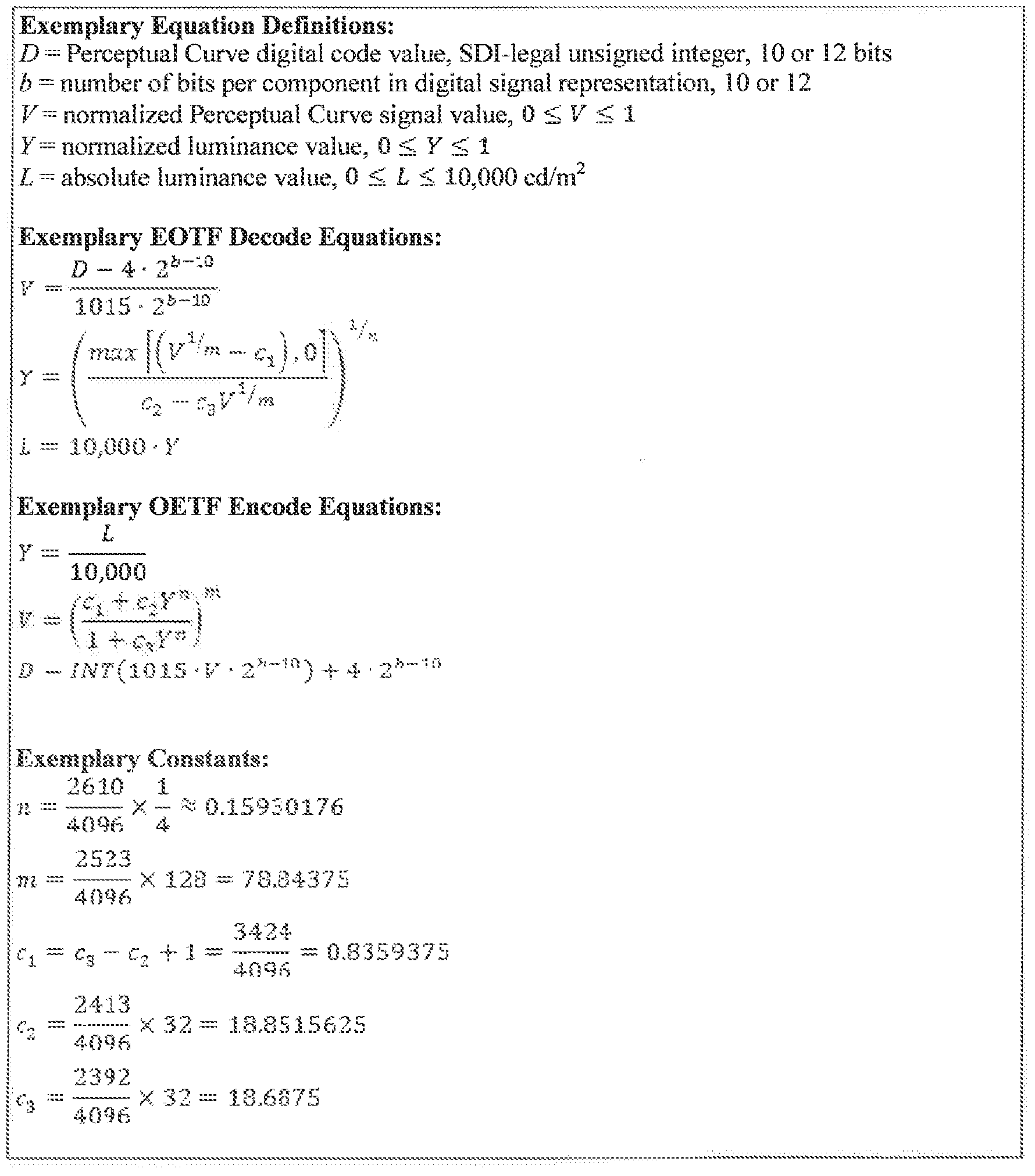


Claims
Priority Applications (64)
| Application Number | Priority Date | Filing Date | Title |
|---|---|---|---|
| KR1020217023802A KR102332475B1 (en) | 2011-12-06 | 2012-12-06 | Method of improving the perceptual luminance nonlinearity-based image data exchange across different display capabilities |
| PL19155297T PL3514677T3 (en) | 2011-12-06 | 2012-12-06 | Device and method of improving the perceptual luminance nonlinearity-based image data exchange across different display capabilities |
| MX2014006445A MX2014006445A (en) | 2011-12-06 | 2012-12-06 | Device and method of improving the perceptual luminance nonlinearity - based image data exchange across different display capabilities. |
| MX2020004850A MX2020004850A (en) | 2011-12-06 | 2012-12-06 | Device and method of improving the perceptual luminance nonlinearity - based image data exchange across different display capabilities. |
| CA2854071A CA2854071C (en) | 2011-12-06 | 2012-12-06 | Device and method of improving the perceptual luminance nonlinearity - based image data exchange across different display capabilities |
| EP22207638.2A EP4160385A1 (en) | 2011-12-06 | 2012-12-06 | Method of improving the perceptual luminance nonlinearity-based image data exchange across different display capabilities |
| KR1020147014175A KR101550592B1 (en) | 2011-12-06 | 2012-12-06 | Device and method of improving the perceptual luminance nonlinearity-based image data exchange across different display capabilities |
| EP16166823.1A EP3079055B1 (en) | 2011-12-06 | 2012-12-06 | Device and method of improving the perceptual luminance nonlinearity-based image data exchange across different display capabilities |
| KR1020217011320A KR102284891B1 (en) | 2011-12-06 | 2012-12-06 | Method of improving the perceptual luminance nonlinearity-based image data exchange across different display capabilities |
| SG11201401944XA SG11201401944XA (en) | 2011-12-06 | 2012-12-06 | Device and method of improving the perceptual luminance nonlinearity - based image data exchange across different display capabilities |
| EP21197681.6A EP3974956B1 (en) | 2011-12-06 | 2012-12-06 | Computer program improving the perceptual nonlinearity-based image data exchange across different display capabilities |
| KR1020197008788A KR102197273B1 (en) | 2011-12-06 | 2012-12-06 | Method of improving the perceptual luminance nonlinearity-based image data exchange across different display capabilities |
| MX2016013417A MX365964B (en) | 2011-12-06 | 2012-12-06 | Device and method of improving the perceptual luminance nonlinearity - based image data exchange across different display capabilities. |
| EP22199319.9A EP4137929A1 (en) | 2011-12-06 | 2012-12-06 | Method of improving the perceptual luminance nonlinearity-based image data exchange across different display capabilities |
| EP19155297.5A EP3514677B1 (en) | 2011-12-06 | 2012-12-06 | Device and method of improving the perceptual luminance nonlinearity-based image data exchange across different display capabilities |
| KR1020187015470A KR102105317B1 (en) | 2011-12-06 | 2012-12-06 | Method of improving the perceptual luminance nonlinearity-based image data exchange across different display capabilities |
| AU2012347820A AU2012347820B2 (en) | 2011-12-06 | 2012-12-06 | Device and method of improving the perceptual luminance nonlinearity - based image data exchange across different display capabilities |
| PL16166823T PL3079055T3 (en) | 2011-12-06 | 2012-12-06 | Device and method of improving the perceptual luminance nonlinearity-based image data exchange across different display capabilities |
| PL20203561T PL3800542T3 (en) | 2011-12-06 | 2012-12-06 | Device and method of improving the perceptual luminance nonlinearity-based image data exchange across different display capabilities |
| KR1020157003365A KR101768435B1 (en) | 2011-12-06 | 2012-12-06 | Device and method of improving the perceptual luminance nonlinearity-based image data exchange across different display capabilities |
| KR1020207008319A KR102197647B1 (en) | 2011-12-06 | 2012-12-06 | Method of improving the perceptual luminance nonlinearity-based image data exchange across different display capabilities |
| KR1020177019999A KR101865543B1 (en) | 2011-12-06 | 2012-12-06 | Device of improving the perceptual luminance nonlinearity-based image data exchange across different display capabilities |
| BR122021018508-5A BR122021018508B1 (en) | 2011-12-06 | 2012-12-06 | METHOD PERFORMED IN AN IMAGING DEVICE AND IMAGING DEVICE |
| EP12808594.1A EP2788855B1 (en) | 2011-12-06 | 2012-12-06 | Device and method of improving the perceptual luminance nonlinearity-based image data exchange across different display capabilities |
| KR1020227011212A KR102446482B1 (en) | 2011-12-06 | 2012-12-06 | Method of improving the perceptual luminance nonlinearity-based image data exchange across different display capabilities |
| KR1020217038376A KR102385015B1 (en) | 2011-12-06 | 2012-12-06 | Method of improving the perceptual luminance nonlinearity-based image data exchange across different display capabilities |
| EP22207637.4A EP4155898A1 (en) | 2011-12-06 | 2012-12-06 | Method of improving the perceptual luminance nonlinearity-based image data exchange across different display capabilities |
| KR1020207036860A KR102245919B1 (en) | 2011-12-06 | 2012-12-06 | Method of improving the perceptual luminance nonlinearity-based image data exchange across different display capabilities |
| KR1020177000411A KR101812469B1 (en) | 2011-12-06 | 2012-12-06 | Method of improving the perceptual luminance nonlinearity-based image data exchange across different display capabilities |
| JP2014546070A JP5735717B2 (en) | 2011-12-06 | 2012-12-06 | Apparatus and method for improving perceptual luminance nonlinearity based image data exchange between different display functions |
| BR112014012927A BR112014012927A2 (en) | 2011-12-06 | 2012-12-06 | device and method for enhancing image data exchange based on perceptual luminance non-linearity across different display capacities |
| MX2016013419A MX365965B (en) | 2011-12-06 | 2012-12-06 | Device and method of improving the perceptual luminance nonlinearity - based image data exchange across different display capabilities. |
| EP20203561.4A EP3800542B1 (en) | 2011-12-06 | 2012-12-06 | Device and method of improving the perceptual luminance nonlinearity-based image data exchange across different display capabilities |
| IN3871CHN2014 IN2014CN03871A (en) | 2011-12-06 | 2012-12-06 | |
| RU2014127489A RU2607618C2 (en) | 2011-12-06 | 2012-12-06 | Device and method of improving perceptual luminance nonlinearity-based image data exchange across different display capabilities |
| EP20203810.5A EP3800543B1 (en) | 2011-12-06 | 2012-12-06 | Computer program for and computer readable medium having stored a bitstream for improving the perceptual luminance nonlinearity-based image data exchange across different display capabilities |
| US14/363,129 US9077994B2 (en) | 2011-12-06 | 2012-12-06 | Device and method of improving the perceptual luminance nonlinearity-based image data exchange across different display capabilities |
| CN201280060408.7A CN103988165B (en) | 2011-12-06 | 2012-12-06 | For reference encoder view data being carried out to method and apparatus and the imaging device of transcoding |
| ES12808594.1T ES2584681T3 (en) | 2011-12-06 | 2012-12-06 | Device and procedure to improve the exchange of image data based on a nonlinearity of perceptual luminance through different display capabilities |
| HK14110936.0A HK1197471A1 (en) | 2011-12-06 | 2014-10-31 | Device and method of improving the perceptual luminance nonlinearity-based image data exchange across different display capabilities |
| HK15100277.7A HK1199955A1 (en) | 2011-12-06 | 2015-01-09 | Device and method of improving the perceptual luminance nonlinearity- based image data exchange across different display capabilities |
| US14/735,875 US9288499B2 (en) | 2011-12-06 | 2015-06-10 | Device and method of improving the perceptual luminance nonlinearity-based image data exchange across different display capabilities |
| US14/925,596 US9521419B2 (en) | 2011-12-06 | 2015-10-28 | Perceptual luminance nonlinearity-based image data exchange across different display capabilities |
| AU2016203103A AU2016203103B2 (en) | 2011-12-06 | 2016-05-12 | Device and Method of Improving the Perceptual Luminance Nonlinearity-Based Image Data Exchange Across Different Display Capabilities |
| AU2016204179A AU2016204179B2 (en) | 2011-12-06 | 2016-06-20 | Device and method of improving the perceptual luminance nonlinearity - based image data exchange across different display capabilities |
| AU2016204177A AU2016204177B2 (en) | 2011-12-06 | 2016-06-20 | Device and method of improving the perceptual luminance nonlinearity - based image data exchange across different display capabilities |
| US15/283,223 US9685139B2 (en) | 2011-12-06 | 2016-09-30 | Perceptual luminance nonlinearity-based image data exchange across different display capabilities |
| US15/283,237 US9697799B2 (en) | 2011-12-06 | 2016-09-30 | Perceptual luminance nonlinearity-based image data exchange across different display capabilities |
| US15/610,499 US9959837B2 (en) | 2011-12-06 | 2017-05-31 | Perceptual luminance nonlinearity-based image data exchange across different display capabilities |
| US15/960,303 US10242650B2 (en) | 2011-12-06 | 2018-04-23 | Perceptual luminance nonlinearity-based image data exchange across different display capabilities |
| AU2018206694A AU2018206694B2 (en) | 2011-12-06 | 2018-07-16 | Device and method of improving the perceptual luminance nonlinearity-based image data exchange across different display capabilities |
| US16/354,106 US10621952B2 (en) | 2011-12-06 | 2019-03-14 | Perceptual luminance nonlinearity-based image data exchange across different display capabilities |
| CY20191100524T CY1121636T1 (en) | 2011-12-06 | 2019-05-16 | APPARATUS AND METHOD FOR IMPROVING IMAGE DATA EXCHANGE BASED ON PERCEIVED BRIGHTNESS NONLINEARITY AT DIFFERENT PROJECTION POSSIBILITIES |
| AU2019264649A AU2019264649B2 (en) | 2011-12-06 | 2019-11-15 | Device and method of improving the perceptual luminance nonlinearity-based image data exchange across different display capabilities |
| US16/812,810 US10957283B2 (en) | 2011-12-06 | 2020-03-09 | Perceptual luminance nonlinearity-based image data exchange across different display capabilities |
| CY20201101132T CY1123605T1 (en) | 2011-12-06 | 2020-11-30 | APPARATUS AND METHOD FOR IMPROVING IMAGE DATA EXCHANGE BASED ON PERCEIVED BRIGHTNESS NONLINEARITY AT DIFFERENT PROJECTION POSSIBILITIES |
| US17/208,886 US11587529B2 (en) | 2011-12-06 | 2021-03-22 | Perceptual luminance nonlinearity-based image data exchange across different display capabilities |
| AU2021201806A AU2021201806B2 (en) | 2011-12-06 | 2021-03-23 | Device and method of improving the perceptual luminance nonlinearity-based image data exchange across different display capabilities |
| AU2022201261A AU2022201261B2 (en) | 2011-12-06 | 2022-02-24 | Device and method of improving the perceptual luminance nonlinearity-based image data exchange across different display capabilities |
| AU2022204421A AU2022204421B2 (en) | 2011-12-06 | 2022-06-23 | Device and method of improving the perceptual luminance nonlinearity-based image data exchange across different display capabilities |
| US17/892,473 US11600244B2 (en) | 2011-12-06 | 2022-08-22 | Perceptual luminance nonlinearity-based image data exchange across different display capabilities |
| US18/076,993 US11887560B2 (en) | 2011-12-06 | 2022-12-07 | Perceptual luminance nonlinearity-based image data exchange across different display capabilities |
| AU2022291562A AU2022291562B2 (en) | 2011-12-06 | 2022-12-22 | Device and method of improving the perceptual luminance nonlinearity-based image data exchange across different display capabilities |
| AU2023204114A AU2023204114A1 (en) | 2011-12-06 | 2023-06-28 | Device and method of improving the perceptual luminance nonlinearity-based image data exchange across different display capabilities |
Applications Claiming Priority (6)
| Application Number | Priority Date | Filing Date | Title |
|---|---|---|---|
| US201161567579P | 2011-12-06 | 2011-12-06 | |
| US61/567,579 | 2011-12-06 | ||
| US201261674503P | 2012-07-23 | 2012-07-23 | |
| US61/674,503 | 2012-07-23 | ||
| US201261703449P | 2012-09-20 | 2012-09-20 | |
| US61/703,449 | 2012-09-20 |
Related Child Applications (2)
| Application Number | Title | Priority Date | Filing Date |
|---|---|---|---|
| US14/363,129 A-371-Of-International US9077994B2 (en) | 2011-12-06 | 2012-12-06 | Device and method of improving the perceptual luminance nonlinearity-based image data exchange across different display capabilities |
| US14/735,875 Continuation US9288499B2 (en) | 2011-12-06 | 2015-06-10 | Device and method of improving the perceptual luminance nonlinearity-based image data exchange across different display capabilities |
Publications (1)
| Publication Number | Publication Date |
|---|---|
| WO2013086169A1 true WO2013086169A1 (en) | 2013-06-13 |
Family
ID=47459140
Family Applications (1)
| Application Number | Title | Priority Date | Filing Date |
|---|---|---|---|
| PCT/US2012/068212 WO2013086169A1 (en) | 2011-12-06 | 2012-12-06 | Device and method of improving the perceptual luminance nonlinearity - based image data exchange across different display capabilities |
Country Status (26)
| Country | Link |
|---|---|
| US (6) | US9077994B2 (en) |
| EP (9) | EP3514677B1 (en) |
| JP (12) | JP5735717B2 (en) |
| KR (12) | KR102105317B1 (en) |
| CN (9) | CN103988165B (en) |
| AU (12) | AU2012347820B2 (en) |
| BR (2) | BR112014012927A2 (en) |
| CA (9) | CA3219049A1 (en) |
| CY (2) | CY1121636T1 (en) |
| DK (5) | DK3514677T3 (en) |
| ES (6) | ES2940345T3 (en) |
| FI (2) | FI3800543T3 (en) |
| HK (2) | HK1197471A1 (en) |
| HR (5) | HRP20230252T1 (en) |
| HU (5) | HUE061490T2 (en) |
| IN (1) | IN2014CN03871A (en) |
| LT (2) | LT3079055T (en) |
| MX (6) | MX2020004850A (en) |
| MY (2) | MY193501A (en) |
| PL (5) | PL3974956T3 (en) |
| PT (5) | PT3800543T (en) |
| RS (5) | RS58774B1 (en) |
| RU (4) | RU2665211C1 (en) |
| SG (4) | SG11201401944XA (en) |
| SI (2) | SI3079055T1 (en) |
| WO (1) | WO2013086169A1 (en) |
Cited By (31)
| Publication number | Priority date | Publication date | Assignee | Title |
|---|---|---|---|---|
| EP2860693A1 (en) | 2013-10-09 | 2015-04-15 | Dolby Laboratories Licensing Corporation | Systems and methods to optimize conversions for wide gamut opponent color spaces |
| US9202438B2 (en) | 2011-09-26 | 2015-12-01 | Dolby Laboratories Licensing Corporation | Image formats and related methods and apparatuses |
| GB2528283A (en) * | 2014-07-16 | 2016-01-20 | Barco Nv | Image colour calibration with multiple colour scales |
| WO2016073285A1 (en) | 2014-11-05 | 2016-05-12 | Apple Inc. | Mapping image/video content to target display devices with variable brightness levels and/or viewing conditions |
| WO2016140954A1 (en) * | 2015-03-02 | 2016-09-09 | Dolby Laboratories Licensing Corporation | Content-adaptive perceptual quantizer for high dynamic range images |
| JP2016533072A (en) * | 2013-07-16 | 2016-10-20 | コーニンクレッカ フィリップス エヌ ヴェKoninklijke Philips N.V. | Method and apparatus for generating EOTF functions for generic code mapping for HDR images, and methods and processes using these images |
| WO2016172394A1 (en) * | 2015-04-21 | 2016-10-27 | Arris Enterprises Llc | Adaptive perceptual mapping and signaling for video coding |
| US20160345032A1 (en) | 2014-02-07 | 2016-11-24 | Sony Corporation | Transmission device, transmission method, reception device, reception method, display device, and display method |
| US9521419B2 (en) | 2011-12-06 | 2016-12-13 | Dolby Laboratories Licensing Corproation | Perceptual luminance nonlinearity-based image data exchange across different display capabilities |
| WO2016199409A1 (en) * | 2015-06-07 | 2016-12-15 | Sharp Kabushiki Kaisha | Systems and methods for optimizing video coding based on a luminance transfer function or video color component values |
| US9538155B2 (en) | 2013-12-04 | 2017-01-03 | Dolby Laboratories Licensing Corporation | Decoding and display of high dynamic range video |
| WO2017003525A1 (en) * | 2015-06-30 | 2017-01-05 | Dolby Laboratories Licensing Corporation | Real-time content-adaptive perceptual quantizer for high dynamic range images |
| US9554020B2 (en) | 2013-11-13 | 2017-01-24 | Dolby Laboratories Licensing Corporation | Workflow for content creation and guided display management of EDR video |
| US9584811B2 (en) | 2013-06-17 | 2017-02-28 | Dolby Laboratories Licensing Corporation | Adaptive reshaping for layered coding of enhanced dynamic range signals |
| WO2017053350A1 (en) * | 2015-09-21 | 2017-03-30 | Dolby Laboratories Licensing Corporation | Techniques for operating a display in the perceptual code space |
| US9648351B2 (en) | 2013-10-24 | 2017-05-09 | Dolby Laboratories Licensing Corporation | Error control in multi-stream EDR video codec |
| US9720231B2 (en) | 2012-09-26 | 2017-08-01 | Dolby Laboratories Licensing Corporation | Display, imaging system and controller for eyewear display device |
| KR20170107463A (en) * | 2015-01-27 | 2017-09-25 | 톰슨 라이센싱 | Methods, systems and apparatus for electro-optical and photo-electrical conversion of images and video |
| US9842385B2 (en) | 2012-09-12 | 2017-12-12 | Dolby Laboratories Licensing Corporation | Display management for images with enhanced dynamic range |
| JP2018046317A (en) * | 2016-09-12 | 2018-03-22 | オンキヨー株式会社 | Video processing apparatus |
| US10242650B2 (en) | 2011-12-06 | 2019-03-26 | Dolby Laboratories Licensing Corporation | Perceptual luminance nonlinearity-based image data exchange across different display capabilities |
| TWI668990B (en) * | 2013-12-19 | 2019-08-11 | 美商內數位Vc專利控股股份有限公司 | Method and device for encoding a high-dynamic range image |
| CN110213459A (en) * | 2014-06-10 | 2019-09-06 | 松下知识产权经营株式会社 | Display methods and display device |
| WO2019185935A1 (en) * | 2018-03-29 | 2019-10-03 | Barco N.V. | Driver for led display |
| CN112492316A (en) * | 2014-12-03 | 2021-03-12 | 松下知识产权经营株式会社 | Decoding device and decoding method |
| CN112492320A (en) * | 2014-12-03 | 2021-03-12 | 松下知识产权经营株式会社 | Decoding device and decoding method |
| JP2021532677A (en) * | 2018-07-31 | 2021-11-25 | エーティーアイ・テクノロジーズ・ユーエルシーAti Technologies Ulc | Effective electro-optical transfer function coding for displays with a limited luminance range |
| US11288781B2 (en) | 2017-06-16 | 2022-03-29 | Dolby Laboratories Licensing Corporation | Efficient end-to-end single layer inverse display management coding |
| US11445202B2 (en) | 2014-02-25 | 2022-09-13 | Apple Inc. | Adaptive transfer function for video encoding and decoding |
| US11711486B2 (en) | 2018-06-18 | 2023-07-25 | Dolby Laboratories Licensing Corporation | Image capture method and systems to preserve apparent contrast of an image |
| GB2600630B (en) * | 2019-07-09 | 2023-08-30 | Koninklijke Philips Nv | Adjustment of display optimization behaviour for HDR images |
Families Citing this family (71)
| Publication number | Priority date | Publication date | Assignee | Title |
|---|---|---|---|---|
| US9661296B2 (en) * | 2012-07-12 | 2017-05-23 | Samsung Electronics Co., Ltd. | Image processing apparatus and method |
| WO2014116715A1 (en) | 2013-01-25 | 2014-07-31 | Dolby Laboratories Licensing Corporation | Global display management based light modulation |
| EP2959682B1 (en) | 2013-02-21 | 2018-12-05 | Dolby Laboratories Licensing Corporation | Display management for high dynamic range video |
| US9712834B2 (en) * | 2013-10-01 | 2017-07-18 | Dolby Laboratories Licensing Corporation | Hardware efficient sparse FIR filtering in video codec |
| WO2015190044A1 (en) | 2014-06-10 | 2015-12-17 | パナソニックIpマネジメント株式会社 | Display system, display method, and display device |
| US9613407B2 (en) | 2014-07-03 | 2017-04-04 | Dolby Laboratories Licensing Corporation | Display management for high dynamic range video |
| US9911179B2 (en) * | 2014-07-18 | 2018-03-06 | Dolby Laboratories Licensing Corporation | Image decontouring in high dynamic range video processing |
| CN105469375B (en) * | 2014-08-28 | 2021-09-07 | 北京三星通信技术研究有限公司 | Method and device for processing high dynamic range panorama |
| CN109151253B (en) | 2014-09-22 | 2020-12-18 | 松下知识产权经营株式会社 | Display device, display method, and reproduction display system |
| JP6302600B2 (en) | 2014-09-26 | 2018-03-28 | ドルビー ラボラトリーズ ライセンシング コーポレイション | Coding and decoding perceptually quantized video content |
| JP6362793B2 (en) | 2015-01-19 | 2018-07-25 | ドルビー ラボラトリーズ ライセンシング コーポレイション | Display management for high dynamic range video |
| EP3051823A1 (en) | 2015-01-27 | 2016-08-03 | Thomson Licensing | Methods, systems and aparatus for electro-optical and opto-electrical conversion of images and video |
| JP6463179B2 (en) * | 2015-03-17 | 2019-01-30 | キヤノン株式会社 | Signal processing apparatus, signal processing method, and imaging apparatus |
| US10484684B2 (en) | 2015-04-22 | 2019-11-19 | Dolby Laboratories Licensing Corporation | Signal reshaping and coding in the IPT-PQ color space |
| JP6731722B2 (en) * | 2015-05-12 | 2020-07-29 | パナソニック インテレクチュアル プロパティ コーポレーション オブ アメリカPanasonic Intellectual Property Corporation of America | Display method and display device |
| JP6760274B2 (en) * | 2015-05-12 | 2020-09-23 | ソニー株式会社 | Image processing device, image processing method, and program |
| JP6663214B2 (en) * | 2015-05-26 | 2020-03-11 | パナソニック インテレクチュアル プロパティ コーポレーション オブ アメリカPanasonic Intellectual Property Corporation of America | Display method and display device |
| US10863202B2 (en) * | 2015-06-12 | 2020-12-08 | Shaoher Pan | Encoding data in a source image with watermark image codes |
| EP3320675A4 (en) * | 2015-07-10 | 2019-03-06 | Telefonaktiebolaget LM Ericsson (publ) | Pixel pre-processing and encoding |
| CN112040237A (en) | 2015-07-16 | 2020-12-04 | 杜比实验室特许公司 | Signal shaping and encoding for HDR and wide color gamut signals |
| US10575005B2 (en) | 2015-07-22 | 2020-02-25 | Dolby Laboratories Licensing Corporation | Video coding and delivery with both spatial and dynamic range scalability |
| JP6320440B2 (en) | 2015-08-04 | 2018-05-09 | ドルビー ラボラトリーズ ライセンシング コーポレイション | Signal reconstruction for high dynamic range signals |
| US10283032B2 (en) | 2015-10-07 | 2019-05-07 | Samsung Display Co., Ltd. | Integrated circuit for nonlinear data encoding |
| US10140953B2 (en) | 2015-10-22 | 2018-11-27 | Dolby Laboratories Licensing Corporation | Ambient-light-corrected display management for high dynamic range images |
| EP3364654B1 (en) | 2015-12-15 | 2021-03-03 | Huawei Technologies Co., Ltd. | High dynamic range image processing method and apparatus |
| WO2017107114A1 (en) | 2015-12-23 | 2017-06-29 | 华为技术有限公司 | Image signal conversion method and apparatus, and terminal device |
| JP6559803B2 (en) * | 2015-12-25 | 2019-08-14 | シャープ株式会社 | Display device, display device control method, control program, and recording medium |
| CN109074775B (en) * | 2016-01-29 | 2022-02-08 | 巴科股份有限公司 | Digital image processing chain and processing block and display comprising same |
| CN107027027B (en) * | 2016-01-31 | 2021-02-12 | 西安电子科技大学 | Image encoding method, image decoding method, image encoding device, image decoding device, and image encoding/decoding system |
| JP6757157B2 (en) * | 2016-03-29 | 2020-09-16 | キヤノン株式会社 | Projection device and its control method |
| US10397586B2 (en) | 2016-03-30 | 2019-08-27 | Dolby Laboratories Licensing Corporation | Chroma reshaping |
| EP3226563B1 (en) | 2016-03-30 | 2021-06-23 | Dolby Laboratories Licensing Corp. | Chroma reshaping |
| EP3745390B1 (en) | 2016-05-27 | 2023-10-04 | Dolby Laboratories Licensing Corporation | Transitioning between video priority and graphics priority |
| JP6912869B2 (en) * | 2016-06-15 | 2021-08-04 | オリンパス株式会社 | Image processing device, image processing program, image processing method |
| JP6729055B2 (en) * | 2016-06-23 | 2020-07-22 | セイコーエプソン株式会社 | Video processing device, display device, and video processing method |
| TWI631505B (en) * | 2016-08-26 | 2018-08-01 | 晨星半導體股份有限公司 | Image processing method applied to a display and associated circuit |
| FR3056872A1 (en) | 2016-09-23 | 2018-03-30 | Ymagis | DIGITAL IMAGE PROCESSING AND PROJECTION METHOD FOR HOME BROADCAST |
| US10296807B2 (en) | 2016-10-04 | 2019-05-21 | Canon Kabushiki Kaisha | Image processing apparatus and image processing method |
| EP3312798A1 (en) * | 2016-10-20 | 2018-04-25 | Thomson Licensing | Method and device for inverse tone mapping |
| JP2018081595A (en) * | 2016-11-17 | 2018-05-24 | キヤノン株式会社 | Image processing device and method and imaging device |
| WO2018160883A1 (en) | 2017-03-03 | 2018-09-07 | Dolby Laboratories Licensing Corporation | Color saturation adjustment in non-uniform color space |
| CN110383801B (en) | 2017-03-03 | 2021-08-10 | 杜比实验室特许公司 | Color saturation adjustment in non-uniform color spaces |
| WO2018160847A1 (en) | 2017-03-03 | 2018-09-07 | Dolby Laboratories Licensing Corporation | Color image modification with approximation function |
| EP3566429B1 (en) | 2017-03-03 | 2021-09-15 | Dolby Laboratories Licensing Corporation | Color image modification with approximation function |
| CN110447051B (en) | 2017-03-20 | 2023-10-31 | 杜比实验室特许公司 | Perceptually preserving contrast and chroma of a reference scene |
| US11252401B2 (en) * | 2017-08-07 | 2022-02-15 | Dolby Laboratories Licensing Corporation | Optically communicating display metadata |
| US10769817B2 (en) * | 2017-08-07 | 2020-09-08 | Samsung Display Co., Ltd. | Measures for image testing |
| US11336895B2 (en) | 2017-09-06 | 2022-05-17 | Dolby Laboratories Licensing Corporation | Tone-curve optimization method and associated video encoder and video decoder |
| US10600163B2 (en) | 2017-11-22 | 2020-03-24 | Interdigital Vc Holdings, Inc. | Method and device for reconstructing a display adapted HDR image |
| US10832613B2 (en) | 2018-03-07 | 2020-11-10 | At&T Intellectual Property I, L.P. | Image format conversion using luminance-adaptive dithering |
| US10931977B2 (en) | 2018-03-15 | 2021-02-23 | Comcast Cable Communications, Llc | Systems, methods, and apparatuses for processing video |
| CA3037026A1 (en) * | 2018-03-15 | 2019-09-15 | Comcast Cable Communications, Llc | Systems, methods, and apparatuses for processing video |
| KR102546990B1 (en) | 2018-03-16 | 2023-06-23 | 엘지전자 주식회사 | Signal processing device and image display apparatus including the same |
| KR20190114332A (en) * | 2018-03-29 | 2019-10-10 | 에스케이하이닉스 주식회사 | Image sensing device and method of operating the image sensing device |
| US10917583B2 (en) * | 2018-04-27 | 2021-02-09 | Apple Inc. | Standard and high dynamic range display systems and methods for high dynamic range displays |
| JP2020003704A (en) * | 2018-06-29 | 2020-01-09 | 株式会社デンソー | Information processing device |
| JP2020017079A (en) * | 2018-07-25 | 2020-01-30 | 株式会社朋栄 | Tone mapping processing, hdr video conversion method by automatic adjustment and update of tone mapping parameter, and device of the same |
| US10802795B2 (en) * | 2018-08-21 | 2020-10-13 | Semiconductor Components Industries, Llc | Systems and methods for image data compression |
| EP3672267A1 (en) * | 2018-12-20 | 2020-06-24 | InterDigital VC Holdings, Inc. | Methods for processing audio and/or video contents and corresponding signal, devices, electronic assembly, system, computer readable program products and computer readable storage media |
| WO2020232537A1 (en) * | 2019-05-17 | 2020-11-26 | Fenoto Technologies Inc. | Electronic paper display system |
| WO2020235109A1 (en) * | 2019-05-23 | 2020-11-26 | Eizo株式会社 | Image display device, image display system, image display method, and computer program |
| JP7370762B2 (en) | 2019-08-20 | 2023-10-30 | キヤノン株式会社 | Imaging device and its control method |
| CN110797038B (en) * | 2019-10-30 | 2020-11-06 | 腾讯科技(深圳)有限公司 | Audio processing method and device, computer equipment and storage medium |
| EP3873096A1 (en) | 2020-02-25 | 2021-09-01 | Koninklijke Philips N.V. | Improved hdr color processing for saturated colors |
| US11343495B2 (en) * | 2020-06-03 | 2022-05-24 | Tencent America LLC | Methods of simplification of temporal filtering |
| CN114449244B (en) * | 2020-10-31 | 2023-07-18 | 华为技术有限公司 | Image quality adjusting method and device |
| CN114822448B (en) * | 2021-01-22 | 2024-04-05 | 广州视创显示科技有限公司 | Image hybrid display method, device, equipment and storage medium |
| EP4341929A1 (en) | 2021-05-19 | 2024-03-27 | Dolby Laboratories Licensing Corporation | Display management with position-varying adaptivity to ambient light and/or non-display-originating surface light |
| KR20220165350A (en) | 2021-06-08 | 2022-12-15 | 대구가톨릭대학교산학협력단 | Reactive- group containing MXenes and Photocurable Resin Composition including the same |
| EP4220539A1 (en) | 2022-01-27 | 2023-08-02 | Koninklijke Philips N.V. | Automatic luminance adjustment for hdr video coding |
| CN116437162B (en) * | 2023-06-12 | 2023-08-22 | 美视信息科技(常州)有限公司 | Information transmission method and device, display and storage medium |
Citations (4)
| Publication number | Priority date | Publication date | Assignee | Title |
|---|---|---|---|---|
| EP0103488A2 (en) * | 1982-09-14 | 1984-03-21 | New York Institute Of Technology | Method and apparatus for encoding and decoding video |
| GB2311432A (en) * | 1996-03-20 | 1997-09-24 | Sony Uk Ltd | Processing an input image |
| JP2000188647A (en) * | 1998-12-21 | 2000-07-04 | Ricoh Co Ltd | Image evaluation method and image evaluation system |
| US20030174284A1 (en) * | 2002-03-12 | 2003-09-18 | Stewart Jeffrey L. | Method and apparatus for measuring contrast sensitivity |
Family Cites Families (112)
| Publication number | Priority date | Publication date | Assignee | Title |
|---|---|---|---|---|
| US5276779A (en) | 1991-04-01 | 1994-01-04 | Eastman Kodak Company | Method for the reproduction of color images based on viewer adaption |
| US6388648B1 (en) | 1996-11-05 | 2002-05-14 | Clarity Visual Systems, Inc. | Color gamut and luminance matching techniques for image display systems |
| JPH1188909A (en) * | 1997-09-11 | 1999-03-30 | Mitsubishi Electric Corp | Image compression transmitter |
| US6148006A (en) * | 1997-11-12 | 2000-11-14 | Nortel Networks Limited | Communication system architecture, exchange having a plurality of broadband modems and method of supporting broadband operation on a one to one basis |
| US6847376B2 (en) | 1998-11-13 | 2005-01-25 | Lightsurf Technologies, Inc. | Method and system for characterizing color display monitor output |
| JP4147655B2 (en) | 1998-12-07 | 2008-09-10 | ソニー株式会社 | Image processing apparatus and image processing method |
| US6370265B1 (en) | 1999-11-24 | 2002-04-09 | Direct Radiography Corp. | Method for generating gray scale transfer functions for use in displaying a digital radiogram |
| US7170477B2 (en) | 2000-04-13 | 2007-01-30 | Sharp Kabushiki Kaisha | Image reproducing method, image display apparatus and picture signal compensation device |
| JP3904841B2 (en) | 2000-05-15 | 2007-04-11 | シャープ株式会社 | Liquid crystal display device, electronic device using the same, and liquid crystal display method |
| JP4766288B2 (en) * | 2000-06-21 | 2011-09-07 | ソニー株式会社 | Information processing device |
| JP2002092655A (en) | 2000-09-20 | 2002-03-29 | Minolta Co Ltd | System and method for displaying three-dimensional virtual reality |
| FI110045B (en) | 2000-11-08 | 2002-11-15 | Antti Lahtinen | Method and apparatus for converting a grayscale image into a pseudo-grayscale image |
| JP3620443B2 (en) | 2000-12-05 | 2005-02-16 | 日産自動車株式会社 | Automotive display device |
| US6989859B2 (en) | 2000-12-22 | 2006-01-24 | Eastman Kodak Company | Camera having user interface ambient sensor viewer adaptation compensation and method |
| US6947079B2 (en) | 2000-12-22 | 2005-09-20 | Eastman Kodak Company | Camera having verification display with reverse white balanced viewer adaptation compensation and method |
| US7019763B2 (en) | 2001-01-09 | 2006-03-28 | Seiko Epson Corporation | Display device, driving method therefor, electro-optical device, driving method therefor, and electronic apparatus |
| US6831947B2 (en) * | 2001-03-23 | 2004-12-14 | Sharp Laboratories Of America, Inc. | Adaptive quantization based on bit rate prediction and prediction error energy |
| US7023580B2 (en) * | 2001-04-20 | 2006-04-04 | Agilent Technologies, Inc. | System and method for digital image tone mapping using an adaptive sigmoidal function based on perceptual preference guidelines |
| DE10300048B4 (en) * | 2002-01-05 | 2005-05-12 | Samsung Electronics Co., Ltd., Suwon | Image coding method for motion picture expert groups, involves image quantizing data in accordance with quantization parameter, and coding entropy of quantized image data using entropy coding unit |
| US7046400B2 (en) | 2002-01-31 | 2006-05-16 | Eastman Kodak Company | Adjusting the color, brightness, and tone scale of rendered digital images |
| JP2003244436A (en) | 2002-02-13 | 2003-08-29 | Konica Corp | Calibration apparatus, calibration method for image output device, program and storage medium |
| US7221807B2 (en) | 2002-03-29 | 2007-05-22 | Sharp Laboratories Of America, Inc. | Methods and systems for digital image characteristic adjustment using a neural network |
| US7609360B2 (en) | 2002-06-17 | 2009-10-27 | Fujifilm Corporation | Image display device |
| US7184057B2 (en) * | 2002-06-24 | 2007-02-27 | Microsoft Corpoartion | Systems and methods for providing color management |
| EP1391865A1 (en) * | 2002-08-23 | 2004-02-25 | Deutsche Thomson-Brandt Gmbh | Plasma display panel (PDP) - Reduction of dithering noise while displaying less video levels than required |
| US7043090B2 (en) | 2002-10-02 | 2006-05-09 | Eastman Kodak Company | Enhancing the tonal characteristics of digital images using expansive and compressive tone scale functions |
| JP4467877B2 (en) | 2002-11-08 | 2010-05-26 | 富士通マイクロエレクトロニクス株式会社 | Display device driving method and display device driving circuit |
| JP2004212598A (en) | 2002-12-27 | 2004-07-29 | Sharp Corp | Converting device, correcting circuit, driving device, display device, inspecting device, and display method |
| JP4410997B2 (en) | 2003-02-20 | 2010-02-10 | パナソニック株式会社 | Display panel drive device |
| JP4396107B2 (en) * | 2003-02-21 | 2010-01-13 | 凸版印刷株式会社 | Video display system |
| US7266229B2 (en) * | 2003-07-24 | 2007-09-04 | Carestream Health, Inc. | Method for rendering digital radiographic images for display based on independent control of fundamental image quality parameters |
| KR100508937B1 (en) | 2003-08-05 | 2005-08-17 | 삼성에스디아이 주식회사 | Method for displaying gray scale on high efficient plasma display panel and plasma display panel driving apparatus using the same |
| DE10338484B4 (en) | 2003-08-21 | 2008-10-16 | Eizo Gmbh | Method and arrangement for optimizing the course of a luminance characteristic |
| US7508387B2 (en) | 2003-09-30 | 2009-03-24 | International Business Machines Corporation | On demand calibration of imaging displays |
| US7412105B2 (en) | 2003-10-03 | 2008-08-12 | Adobe Systems Incorporated | Tone selective adjustment of images |
| JP2005117590A (en) | 2003-10-10 | 2005-04-28 | Konica Minolta Medical & Graphic Inc | Radioactive ray image photographing system and radioactive ray image sensing processor |
| EP1544837A1 (en) * | 2003-12-17 | 2005-06-22 | Deutsche Thomson-Brandt Gmbh | Method and device for reducing the effect of differences in scan line load |
| EP1544838A1 (en) * | 2003-12-17 | 2005-06-22 | Deutsche Thomson-Brandt Gmbh | Method and device for compensating effect of differences in subfield load |
| US7164284B2 (en) | 2003-12-18 | 2007-01-16 | Sharp Laboratories Of America, Inc. | Dynamic gamma for a liquid crystal display |
| US20050190836A1 (en) * | 2004-01-30 | 2005-09-01 | Jiuhuai Lu | Process for maximizing the effectiveness of quantization matrices in video codec systems |
| JP4632721B2 (en) * | 2004-03-18 | 2011-02-16 | メガビジョン株式会社 | Processing apparatus and gamma adjustment program |
| EP1587049A1 (en) | 2004-04-15 | 2005-10-19 | Barco N.V. | Method and device for improving conformance of a display panel to a display standard in the whole display area and for different viewing angles |
| US8218625B2 (en) * | 2004-04-23 | 2012-07-10 | Dolby Laboratories Licensing Corporation | Encoding, decoding and representing high dynamic range images |
| WO2006003602A1 (en) | 2004-06-30 | 2006-01-12 | Koninklijke Philips Electronics N.V. | Dominant color extraction for ambient light derived from video content mapped through unrendered color space |
| KR20070032992A (en) | 2004-07-13 | 2007-03-23 | 코닌클리케 필립스 일렉트로닉스 엔.브이. | Standardized digital image viewing with ambient light control |
| US7283654B2 (en) | 2004-08-26 | 2007-10-16 | Lumeniq, Inc. | Dynamic contrast visualization (DCV) |
| EP1650736A1 (en) | 2004-10-25 | 2006-04-26 | Barco NV | Backlight modulation for display |
| US7782405B2 (en) | 2004-12-02 | 2010-08-24 | Sharp Laboratories Of America, Inc. | Systems and methods for selecting a display source light illumination level |
| WO2006066380A1 (en) * | 2004-12-23 | 2006-06-29 | Dolby Canada Corporation | Wide color gamut displays |
| US7372507B2 (en) | 2005-02-08 | 2008-05-13 | Texas Instruments Incorporated | Real-time content based gamma adjustment for digital video display |
| US20060197968A1 (en) | 2005-03-01 | 2006-09-07 | Vannostrand S L | Dicom print driver |
| US7606429B2 (en) * | 2005-03-25 | 2009-10-20 | Ati Technologies Ulc | Block-based image compression method and apparatus |
| WO2007014681A1 (en) * | 2005-08-01 | 2007-02-08 | Barco N.V. | Method and device for improved display standard conformance |
| US7495679B2 (en) * | 2005-08-02 | 2009-02-24 | Kolorific, Inc. | Method and system for automatically calibrating a color display |
| JP4529888B2 (en) | 2005-12-07 | 2010-08-25 | ブラザー工業株式会社 | Image processing apparatus, image processing method, and image processing program |
| WO2008007301A2 (en) | 2006-07-10 | 2008-01-17 | Koninklijke Philips Electronics, N.V. | System and method for dicom compliant display of ultrasound images in varying ambient light |
| KR101243817B1 (en) | 2006-07-28 | 2013-03-18 | 엘지디스플레이 주식회사 | Flat panel display and data multi-modulation method thereof |
| US7990427B2 (en) | 2006-08-21 | 2011-08-02 | Micron Technology, Inc. | Method and apparatus for applying tonal correction to images |
| US20080170031A1 (en) | 2007-01-17 | 2008-07-17 | Chia-Hui Kuo | Method for performing chromatic adaptation while displaying image, and corresponding display circuit and device |
| US8026908B2 (en) | 2007-02-05 | 2011-09-27 | Dreamworks Animation Llc | Illuminated surround and method for operating same for video and other displays |
| KR100855472B1 (en) * | 2007-02-07 | 2008-09-01 | 삼성전자주식회사 | Apparatus and method for driving low-power |
| US7826681B2 (en) | 2007-02-28 | 2010-11-02 | Sharp Laboratories Of America, Inc. | Methods and systems for surround-specific display modeling |
| JP2008234315A (en) * | 2007-03-20 | 2008-10-02 | Toyota Motor Corp | Gradation compression method and gradation compression device for digital image |
| WO2009002316A1 (en) | 2007-06-27 | 2008-12-31 | Thomson Licensing | System and method for color correction between displays with and without average picture dependency |
| US8135230B2 (en) * | 2007-07-30 | 2012-03-13 | Dolby Laboratories Licensing Corporation | Enhancing dynamic ranges of images |
| EP2063647A1 (en) | 2007-11-24 | 2009-05-27 | Barco NV | Calibration of a 3-dimensional display |
| US20110129148A1 (en) | 2007-12-17 | 2011-06-02 | Pavel Kisilev | Image processing using target values |
| US8179363B2 (en) | 2007-12-26 | 2012-05-15 | Sharp Laboratories Of America, Inc. | Methods and systems for display source light management with histogram manipulation |
| CN101478687B (en) * | 2008-01-04 | 2010-12-08 | 华晶科技股份有限公司 | Correcting method for pseudo color pixel in digital image |
| US8199995B2 (en) | 2008-01-29 | 2012-06-12 | Carestream Health, Inc. | Sensitometric response mapping for radiological images |
| JP2009211048A (en) * | 2008-02-06 | 2009-09-17 | Canon Inc | Image signal processing apparatus and image signal processing method |
| US8593476B2 (en) | 2008-02-13 | 2013-11-26 | Gary Demos | System for accurately and precisely representing image color information |
| JP4334596B2 (en) * | 2008-02-27 | 2009-09-30 | 株式会社東芝 | Display device |
| WO2009125663A1 (en) | 2008-04-09 | 2009-10-15 | シャープ株式会社 | Display device and television receiver |
| US8531379B2 (en) | 2008-04-28 | 2013-09-10 | Sharp Laboratories Of America, Inc. | Methods and systems for image compensation for ambient conditions |
| JP4956488B2 (en) | 2008-06-10 | 2012-06-20 | 株式会社東芝 | Image processing apparatus and image display apparatus |
| JP5274908B2 (en) | 2008-06-20 | 2013-08-28 | 本田技研工業株式会社 | Fuel cell stack |
| TWI383228B (en) | 2008-07-02 | 2013-01-21 | Chunghwa Picture Tubes Ltd | Acitve device array substrate and liquid crystal display panel and driving method thereof |
| US8416179B2 (en) | 2008-07-10 | 2013-04-09 | Sharp Laboratories Of America, Inc. | Methods and systems for color preservation with a color-modulated backlight |
| US8610654B2 (en) * | 2008-07-18 | 2013-12-17 | Sharp Laboratories Of America, Inc. | Correction of visible mura distortions in displays using filtered mura reduction and backlight control |
| JP4901821B2 (en) * | 2008-07-24 | 2012-03-21 | 株式会社東芝 | Image processing apparatus and image processing method |
| EP2308375B1 (en) | 2008-07-28 | 2016-09-07 | NEC Display Solutions, Ltd. | Gray scale display device |
| JP5188334B2 (en) * | 2008-09-04 | 2013-04-24 | キヤノン株式会社 | Image processing apparatus, image processing method, and program |
| CA2736270C (en) * | 2008-09-30 | 2016-04-12 | Dolby Laboratories Licensing Corporation | Systems and methods for applying adaptive gamma in image processing for high brightness and high dynamic range displays |
| JP2012505460A (en) * | 2008-10-13 | 2012-03-01 | コーニンクレッカ フィリップス エレクトロニクス エヌ ヴィ | Image contrast enhancement |
| US8111307B2 (en) * | 2008-10-25 | 2012-02-07 | Omnivision Technologies, Inc. | Defective color and panchromatic CFA image |
| JP2010114839A (en) | 2008-11-10 | 2010-05-20 | Canon Inc | Image processing device and image processing method |
| GB0901825D0 (en) | 2009-02-05 | 2009-03-11 | Univ Cardiff | Displaying image data |
| US8290295B2 (en) | 2009-03-03 | 2012-10-16 | Microsoft Corporation | Multi-modal tone-mapping of images |
| EP2406943B1 (en) * | 2009-03-10 | 2016-06-15 | Dolby Laboratories Licensing Corporation | Extended dynamic range and extended dimensionality image signal conversion |
| US8390642B2 (en) | 2009-04-30 | 2013-03-05 | Hewlett-Packard Development Company, L.P. | System and method for color space setting adjustment |
| CN101620819B (en) * | 2009-06-25 | 2013-10-16 | 北京中星微电子有限公司 | Dynamic regulation method and dynamic regulation device for displaying image back light brightness, and moving display device |
| CN102667899A (en) | 2009-11-27 | 2012-09-12 | 佳能株式会社 | Image display apparatus |
| JP2011133877A (en) * | 2009-11-27 | 2011-07-07 | Canon Inc | Image display device, and image processing device |
| CN101710995B (en) * | 2009-12-10 | 2011-02-16 | 武汉大学 | Video coding system based on vision characteristic |
| CN101950528B (en) * | 2009-12-31 | 2012-06-27 | 四川虹欧显示器件有限公司 | Linear adjustment method of gray scales of PDP (Plasma Display Panel) |
| US8866837B2 (en) | 2010-02-02 | 2014-10-21 | Microsoft Corporation | Enhancement of images for display on liquid crystal displays |
| GB201002632D0 (en) * | 2010-02-16 | 2010-03-31 | Im Sense Ltd | Method and system for generating enhanced images |
| JP5899120B2 (en) * | 2010-03-03 | 2016-04-06 | コーニンクレッカ フィリップス エヌ ヴェKoninklijke Philips N.V. | Apparatus and method for defining a color regime |
| JP5484977B2 (en) * | 2010-03-23 | 2014-05-07 | オリンパス株式会社 | Fluorescence observation equipment |
| US8760578B2 (en) * | 2010-04-19 | 2014-06-24 | Dolby Laboratories Licensing Corporation | Quality assessment of high dynamic range, visual dynamic range and wide color gamut image and video |
| CN102024266B (en) * | 2010-11-04 | 2012-07-25 | 西安电子科技大学 | Image structure model-based compressed sensing image reconstruction method |
| US20120182278A1 (en) | 2011-01-17 | 2012-07-19 | Dolby Laboratories Licensing Corporation | Methods and Apparatus for Estimating Light Adaptation Levels of Persons Viewing Displays |
| TWI538474B (en) | 2011-03-15 | 2016-06-11 | 杜比實驗室特許公司 | Methods and apparatus for image data transformation |
| CN102142145B (en) * | 2011-03-22 | 2012-12-19 | 宁波大学 | Image quality objective evaluation method based on human eye visual characteristics |
| EP2518719B1 (en) | 2011-04-08 | 2016-05-18 | Dolby Laboratories Licensing Corporation | Image range expansion control methods and apparatus |
| CN102170581B (en) * | 2011-05-05 | 2013-03-20 | 天津大学 | Human-visual-system (HVS)-based structural similarity (SSIM) and characteristic matching three-dimensional image quality evaluation method |
| CN102222460B (en) * | 2011-06-10 | 2013-06-05 | 四川虹欧显示器件有限公司 | Method for improving PDP (Plasma Display Panel) image |
| US8988552B2 (en) | 2011-09-26 | 2015-03-24 | Dolby Laboratories Licensing Corporation | Image formats and related methods and apparatuses |
| PE20141864A1 (en) | 2011-09-27 | 2014-12-12 | Koninkl Philips Nv | APPARATUS AND METHOD FOR TRANSFORMING THE DYNAMIC RANGE OF IMAGES |
| CN102420988B (en) * | 2011-12-02 | 2013-11-20 | 上海大学 | Multi-view video coding system utilizing visual characteristics |
| PT3800543T (en) | 2011-12-06 | 2023-02-20 | Dolby Laboratories Licensing Corp | Device and method of improving the perceptual luminance nonlinearity-based image data exchange across different display capabilities |
-
2012
- 2012-12-06 PT PT202038105T patent/PT3800543T/en unknown
- 2012-12-06 CA CA3219049A patent/CA3219049A1/en active Pending
- 2012-12-06 WO PCT/US2012/068212 patent/WO2013086169A1/en active Application Filing
- 2012-12-06 CN CN201280060408.7A patent/CN103988165B/en active Active
- 2012-12-06 MY MYPI2017001794A patent/MY193501A/en unknown
- 2012-12-06 HR HRP20230252TT patent/HRP20230252T1/en unknown
- 2012-12-06 KR KR1020187015470A patent/KR102105317B1/en active IP Right Grant
- 2012-12-06 PT PT191552975T patent/PT3514677T/en unknown
- 2012-12-06 DK DK19155297.5T patent/DK3514677T3/en active
- 2012-12-06 KR KR1020197008788A patent/KR102197273B1/en active IP Right Grant
- 2012-12-06 CN CN201610238078.6A patent/CN106095357B/en active Active
- 2012-12-06 AU AU2012347820A patent/AU2012347820B2/en active Active
- 2012-12-06 SG SG11201401944XA patent/SG11201401944XA/en unknown
- 2012-12-06 EP EP19155297.5A patent/EP3514677B1/en active Active
- 2012-12-06 CA CA3198207A patent/CA3198207C/en active Active
- 2012-12-06 CN CN201610238008.0A patent/CN106095353B/en active Active
- 2012-12-06 KR KR1020217023802A patent/KR102332475B1/en active IP Right Grant
- 2012-12-06 EP EP22207638.2A patent/EP4160385A1/en active Pending
- 2012-12-06 DK DK21197681.6T patent/DK3974956T3/en active
- 2012-12-06 ES ES21197681T patent/ES2940345T3/en active Active
- 2012-12-06 BR BR112014012927A patent/BR112014012927A2/en not_active Application Discontinuation
- 2012-12-06 ES ES12808594.1T patent/ES2584681T3/en active Active
- 2012-12-06 ES ES20203810T patent/ES2939867T3/en active Active
- 2012-12-06 DK DK20203561.4T patent/DK3800542T3/en active
- 2012-12-06 US US14/363,129 patent/US9077994B2/en active Active
- 2012-12-06 MX MX2020004850A patent/MX2020004850A/en unknown
- 2012-12-06 IN IN3871CHN2014 patent/IN2014CN03871A/en unknown
- 2012-12-06 CA CA3114379A patent/CA3114379C/en active Active
- 2012-12-06 EP EP16166823.1A patent/EP3079055B1/en active Active
- 2012-12-06 CN CN201610237989.7A patent/CN106095352B/en active Active
- 2012-12-06 KR KR1020217038376A patent/KR102385015B1/en active IP Right Grant
- 2012-12-06 LT LTEP16166823.1T patent/LT3079055T/en unknown
- 2012-12-06 FI FIEP20203810.5T patent/FI3800543T3/en active
- 2012-12-06 JP JP2014546070A patent/JP5735717B2/en not_active Expired - Fee Related
- 2012-12-06 PL PL21197681.6T patent/PL3974956T3/en unknown
- 2012-12-06 PL PL16166823T patent/PL3079055T3/en unknown
- 2012-12-06 RS RS20190645A patent/RS58774B1/en unknown
- 2012-12-06 PL PL20203810.5T patent/PL3800543T3/en unknown
- 2012-12-06 EP EP21197681.6A patent/EP3974956B1/en active Active
- 2012-12-06 CN CN201610238033.9A patent/CN106095355B/en active Active
- 2012-12-06 HU HUE20203810A patent/HUE061490T2/en unknown
- 2012-12-06 MX MX2016013417A patent/MX365964B/en unknown
- 2012-12-06 ES ES16166823T patent/ES2727965T3/en active Active
- 2012-12-06 KR KR1020177019999A patent/KR101865543B1/en not_active Application Discontinuation
- 2012-12-06 HU HUE16166823A patent/HUE043319T2/en unknown
- 2012-12-06 HU HUE19155297A patent/HUE052566T2/en unknown
- 2012-12-06 RU RU2016149481A patent/RU2665211C1/en active
- 2012-12-06 SI SI201231608T patent/SI3079055T1/en unknown
- 2012-12-06 FI FIEP21197681.6T patent/FI3974956T3/en active
- 2012-12-06 CA CA2854071A patent/CA2854071C/en active Active
- 2012-12-06 KR KR1020147014175A patent/KR101550592B1/en active IP Right Grant
- 2012-12-06 KR KR1020207036860A patent/KR102245919B1/en active IP Right Grant
- 2012-12-06 MX MX2016013419A patent/MX365965B/en unknown
- 2012-12-06 PL PL19155297T patent/PL3514677T3/en unknown
- 2012-12-06 BR BR122021018508-5A patent/BR122021018508B1/en active IP Right Grant
- 2012-12-06 PT PT16166823T patent/PT3079055T/en unknown
- 2012-12-06 CN CN201610238034.3A patent/CN106095356B/en active Active
- 2012-12-06 EP EP20203561.4A patent/EP3800542B1/en active Active
- 2012-12-06 CA CA3114448A patent/CA3114448C/en active Active
- 2012-12-06 EP EP20203810.5A patent/EP3800543B1/en active Active
- 2012-12-06 CN CN201610238028.8A patent/CN106095354B/en active Active
- 2012-12-06 RU RU2014127489A patent/RU2607618C2/en active
- 2012-12-06 SG SG10201604130UA patent/SG10201604130UA/en unknown
- 2012-12-06 HR HRP20230225TT patent/HRP20230225T1/en unknown
- 2012-12-06 MY MYPI2014001354A patent/MY167086A/en unknown
- 2012-12-06 PT PT202035614T patent/PT3800542T/en unknown
- 2012-12-06 SG SG10201604112PA patent/SG10201604112PA/en unknown
- 2012-12-06 EP EP22207637.4A patent/EP4155898A1/en active Pending
- 2012-12-06 RS RS20201431A patent/RS61119B1/en unknown
- 2012-12-06 CA CA2933940A patent/CA2933940C/en active Active
- 2012-12-06 HU HUE21197681A patent/HUE061704T2/en unknown
- 2012-12-06 EP EP12808594.1A patent/EP2788855B1/en active Active
- 2012-12-06 CN CN201610238087.5A patent/CN106095358B/en active Active
- 2012-12-06 MX MX2014006445A patent/MX2014006445A/en unknown
- 2012-12-06 RS RS20230184A patent/RS64033B1/en unknown
- 2012-12-06 RS RS20230171A patent/RS64021B1/en unknown
- 2012-12-06 PL PL20203561T patent/PL3800542T3/en unknown
- 2012-12-06 RS RS20211371A patent/RS62554B1/en unknown
- 2012-12-06 KR KR1020157003365A patent/KR101768435B1/en active IP Right Grant
- 2012-12-06 KR KR1020177000411A patent/KR101812469B1/en active IP Right Grant
- 2012-12-06 DK DK20203810.5T patent/DK3800543T3/en active
- 2012-12-06 CA CA3218784A patent/CA3218784A1/en active Pending
- 2012-12-06 KR KR1020207008319A patent/KR102197647B1/en active IP Right Grant
- 2012-12-06 SI SI201231858T patent/SI3514677T1/en unknown
- 2012-12-06 CA CA3198226A patent/CA3198226A1/en active Pending
- 2012-12-06 DK DK16166823.1T patent/DK3079055T3/en active
- 2012-12-06 CN CN201610237970.2A patent/CN106095351B/en active Active
- 2012-12-06 SG SG10201607838PA patent/SG10201607838PA/en unknown
- 2012-12-06 HU HUE20203561A patent/HUE056242T2/en unknown
- 2012-12-06 CA CA3006841A patent/CA3006841C/en active Active
- 2012-12-06 PT PT211976816T patent/PT3974956T/en unknown
- 2012-12-06 LT LTEP19155297.5T patent/LT3514677T/en unknown
- 2012-12-06 KR KR1020217011320A patent/KR102284891B1/en active IP Right Grant
- 2012-12-06 ES ES19155297T patent/ES2835379T3/en active Active
- 2012-12-06 HR HRP20211707TT patent/HRP20211707T1/en unknown
- 2012-12-06 EP EP22199319.9A patent/EP4137929A1/en active Pending
- 2012-12-06 KR KR1020227011212A patent/KR102446482B1/en active IP Right Grant
- 2012-12-06 ES ES20203561T patent/ES2899579T3/en active Active
-
2014
- 2014-05-29 MX MX2019007437A patent/MX2019007437A/en active IP Right Grant
- 2014-05-29 MX MX2019007447A patent/MX2019007447A/en active IP Right Grant
- 2014-10-31 HK HK14110936.0A patent/HK1197471A1/en unknown
-
2015
- 2015-01-09 HK HK15100277.7A patent/HK1199955A1/en unknown
- 2015-03-04 JP JP2015042448A patent/JP5951827B2/en active Active
- 2015-06-10 US US14/735,875 patent/US9288499B2/en active Active
- 2015-10-28 US US14/925,596 patent/US9521419B2/en active Active
-
2016
- 2016-02-23 JP JP2016032053A patent/JP6180566B2/en active Active
- 2016-05-12 AU AU2016203103A patent/AU2016203103B2/en active Active
- 2016-05-12 AU AU2016203100A patent/AU2016203100B2/en active Active
- 2016-06-08 JP JP2016114271A patent/JP6366641B2/en active Active
- 2016-06-20 AU AU2016204177A patent/AU2016204177B2/en active Active
- 2016-06-20 AU AU2016204179A patent/AU2016204179B2/en active Active
- 2016-09-30 US US15/283,223 patent/US9685139B2/en active Active
- 2016-09-30 US US15/283,237 patent/US9697799B2/en active Active
-
2017
- 2017-05-31 US US15/610,499 patent/US9959837B2/en active Active
-
2018
- 2018-07-03 JP JP2018126576A patent/JP6640929B2/en active Active
- 2018-07-16 AU AU2018206694A patent/AU2018206694B2/en active Active
- 2018-08-17 RU RU2018129961A patent/RU2711102C1/en active
-
2019
- 2019-04-29 HR HRP20190794TT patent/HRP20190794T1/en unknown
- 2019-05-16 CY CY20191100524T patent/CY1121636T1/en unknown
- 2019-11-15 AU AU2019264649A patent/AU2019264649B2/en active Active
- 2019-12-18 RU RU2019142091A patent/RU2728845C1/en active
- 2019-12-26 JP JP2019235968A patent/JP7091306B2/en active Active
-
2020
- 2020-11-27 HR HRP20201891TT patent/HRP20201891T1/en unknown
- 2020-11-30 CY CY20201101132T patent/CY1123605T1/en unknown
- 2020-12-15 JP JP2020207643A patent/JP7432496B2/en active Active
-
2021
- 2021-03-23 AU AU2021201806A patent/AU2021201806B2/en active Active
-
2022
- 2022-02-24 AU AU2022201261A patent/AU2022201261B2/en active Active
- 2022-03-23 JP JP2022046929A patent/JP7246542B2/en active Active
- 2022-04-20 JP JP2022069499A patent/JP2022106814A/en active Pending
- 2022-06-23 AU AU2022204421A patent/AU2022204421B2/en active Active
- 2022-12-22 AU AU2022291562A patent/AU2022291562B2/en active Active
-
2023
- 2023-03-14 JP JP2023039816A patent/JP7421674B2/en active Active
- 2023-06-28 AU AU2023204114A patent/AU2023204114A1/en active Pending
- 2023-11-22 JP JP2023197806A patent/JP2024009174A/en active Pending
- 2023-11-22 JP JP2023197807A patent/JP2024009175A/en active Pending
Patent Citations (4)
| Publication number | Priority date | Publication date | Assignee | Title |
|---|---|---|---|---|
| EP0103488A2 (en) * | 1982-09-14 | 1984-03-21 | New York Institute Of Technology | Method and apparatus for encoding and decoding video |
| GB2311432A (en) * | 1996-03-20 | 1997-09-24 | Sony Uk Ltd | Processing an input image |
| JP2000188647A (en) * | 1998-12-21 | 2000-07-04 | Ricoh Co Ltd | Image evaluation method and image evaluation system |
| US20030174284A1 (en) * | 2002-03-12 | 2003-09-18 | Stewart Jeffrey L. | Method and apparatus for measuring contrast sensitivity |
Non-Patent Citations (2)
| Title |
|---|
| PETER G. J. BARTEN, CONTRAST SENSITIVITY OF THE HUMAN EYE AND ITS FFFECTS ON IMAGE QUALITY, 1999 |
| SCOTT DALY: "Digital Images and Human Vision", 1993, MIT PRESS |
Cited By (78)
| Publication number | Priority date | Publication date | Assignee | Title |
|---|---|---|---|---|
| US9420196B2 (en) | 2011-09-26 | 2016-08-16 | Dolby Laboratories Licensing Corporation | Image formats and related methods and apparatuses |
| US9685120B2 (en) | 2011-09-26 | 2017-06-20 | Dolby Laboratories Licensing Corporation | Image formats and related methods and apparatuses |
| US9202438B2 (en) | 2011-09-26 | 2015-12-01 | Dolby Laboratories Licensing Corporation | Image formats and related methods and apparatuses |
| US10242650B2 (en) | 2011-12-06 | 2019-03-26 | Dolby Laboratories Licensing Corporation | Perceptual luminance nonlinearity-based image data exchange across different display capabilities |
| US9685139B2 (en) | 2011-12-06 | 2017-06-20 | Dolby Laboratories Licensing Corporation | Perceptual luminance nonlinearity-based image data exchange across different display capabilities |
| US11887560B2 (en) | 2011-12-06 | 2024-01-30 | Dolby Laboratories Licensing Corporation | Perceptual luminance nonlinearity-based image data exchange across different display capabilities |
| US11587529B2 (en) | 2011-12-06 | 2023-02-21 | Dolby Laboratories Licensing Corporation | Perceptual luminance nonlinearity-based image data exchange across different display capabilities |
| US11600244B2 (en) | 2011-12-06 | 2023-03-07 | Dolby Laboratories Licensing Corporation | Perceptual luminance nonlinearity-based image data exchange across different display capabilities |
| US10957283B2 (en) | 2011-12-06 | 2021-03-23 | Dolby Laboratories Licensing Corporation | Perceptual luminance nonlinearity-based image data exchange across different display capabilities |
| US10621952B2 (en) | 2011-12-06 | 2020-04-14 | Dolby Laboratories Licensing Corporation | Perceptual luminance nonlinearity-based image data exchange across different display capabilities |
| US9521419B2 (en) | 2011-12-06 | 2016-12-13 | Dolby Laboratories Licensing Corproation | Perceptual luminance nonlinearity-based image data exchange across different display capabilities |
| US9959837B2 (en) | 2011-12-06 | 2018-05-01 | Dolby Laboratories Licensin Corporation | Perceptual luminance nonlinearity-based image data exchange across different display capabilities |
| US9697799B2 (en) | 2011-12-06 | 2017-07-04 | Dolby Laboratories Licensing Corporation | Perceptual luminance nonlinearity-based image data exchange across different display capabilities |
| US9842385B2 (en) | 2012-09-12 | 2017-12-12 | Dolby Laboratories Licensing Corporation | Display management for images with enhanced dynamic range |
| US9720231B2 (en) | 2012-09-26 | 2017-08-01 | Dolby Laboratories Licensing Corporation | Display, imaging system and controller for eyewear display device |
| US9716887B2 (en) | 2013-06-17 | 2017-07-25 | Dolby Laboratories Licensing Corporation | Chromaticity translations in coding of enhanced dynamic range signals |
| US9584811B2 (en) | 2013-06-17 | 2017-02-28 | Dolby Laboratories Licensing Corporation | Adaptive reshaping for layered coding of enhanced dynamic range signals |
| JP2016533072A (en) * | 2013-07-16 | 2016-10-20 | コーニンクレッカ フィリップス エヌ ヴェKoninklijke Philips N.V. | Method and apparatus for generating EOTF functions for generic code mapping for HDR images, and methods and processes using these images |
| US9179042B2 (en) | 2013-10-09 | 2015-11-03 | Dolby Laboratories Licensing Corporation | Systems and methods to optimize conversions for wide gamut opponent color spaces |
| EP2860693A1 (en) | 2013-10-09 | 2015-04-15 | Dolby Laboratories Licensing Corporation | Systems and methods to optimize conversions for wide gamut opponent color spaces |
| US9648351B2 (en) | 2013-10-24 | 2017-05-09 | Dolby Laboratories Licensing Corporation | Error control in multi-stream EDR video codec |
| US9554020B2 (en) | 2013-11-13 | 2017-01-24 | Dolby Laboratories Licensing Corporation | Workflow for content creation and guided display management of EDR video |
| US9538155B2 (en) | 2013-12-04 | 2017-01-03 | Dolby Laboratories Licensing Corporation | Decoding and display of high dynamic range video |
| TWI668990B (en) * | 2013-12-19 | 2019-08-11 | 美商內數位Vc專利控股股份有限公司 | Method and device for encoding a high-dynamic range image |
| US10574987B2 (en) | 2013-12-19 | 2020-02-25 | Interdigital Vc Holdings, Inc. | Method and device for encoding a high-dynamic range image |
| US10313709B2 (en) | 2014-02-07 | 2019-06-04 | Sony Corporation | Transmission device, transmission method, reception device, reception method, display device, and display method |
| US11290754B2 (en) | 2014-02-07 | 2022-03-29 | Sony Corporation | Transmission device, transmission method, reception device, reception method, display device, and display method |
| US20160345032A1 (en) | 2014-02-07 | 2016-11-24 | Sony Corporation | Transmission device, transmission method, reception device, reception method, display device, and display method |
| US11882320B2 (en) | 2014-02-07 | 2024-01-23 | Sony Corporation | Transmission device, transmission method, reception device, reception method, display device, and display method |
| US11716493B2 (en) | 2014-02-07 | 2023-08-01 | Sony Group Corporation | Transmission device, transmission method, reception device, reception method, display device, and display method |
| US11323752B2 (en) | 2014-02-07 | 2022-05-03 | Sony Corporation | Transmission device, transmission method, reception device, reception method, display device, and display method |
| US11595704B2 (en) | 2014-02-07 | 2023-02-28 | Sony Group Corporation | Transmission device, transmission method, reception device, reception method, display device, and display method |
| US11418820B2 (en) | 2014-02-07 | 2022-08-16 | Sony Corporation | Transmission device, transmission method, reception device, reception method, display device, and display method |
| US11445202B2 (en) | 2014-02-25 | 2022-09-13 | Apple Inc. | Adaptive transfer function for video encoding and decoding |
| CN110213459A (en) * | 2014-06-10 | 2019-09-06 | 松下知识产权经营株式会社 | Display methods and display device |
| US10212312B2 (en) | 2014-07-16 | 2019-02-19 | Barco Nv | Image colour calibration with multiple colour scales |
| CN106716491A (en) * | 2014-07-16 | 2017-05-24 | 巴科股份有限公司 | Image color calibration with multiple color scales |
| GB2528283A (en) * | 2014-07-16 | 2016-01-20 | Barco Nv | Image colour calibration with multiple colour scales |
| CN106716491B (en) * | 2014-07-16 | 2020-10-09 | 巴科股份有限公司 | Image color calibration with multiple color scales |
| GB2528283B (en) * | 2014-07-16 | 2020-08-05 | Barco Nv | Image colour calibration with multiple colour scales |
| US10063824B2 (en) | 2014-11-05 | 2018-08-28 | Apple Inc. | Mapping image/video content to target display devices with variable brightness levels and/or viewing conditions |
| WO2016073285A1 (en) | 2014-11-05 | 2016-05-12 | Apple Inc. | Mapping image/video content to target display devices with variable brightness levels and/or viewing conditions |
| CN112492320A (en) * | 2014-12-03 | 2021-03-12 | 松下知识产权经营株式会社 | Decoding device and decoding method |
| CN112492316A (en) * | 2014-12-03 | 2021-03-12 | 松下知识产权经营株式会社 | Decoding device and decoding method |
| CN112492316B (en) * | 2014-12-03 | 2024-03-26 | 松下知识产权经营株式会社 | Decoding device and decoding method |
| JP2018506938A (en) * | 2015-01-27 | 2018-03-08 | トムソン ライセンシングThomson Licensing | Method, system, and apparatus for electro-optical and opto-electrical conversion of images and video |
| US10999607B2 (en) | 2015-01-27 | 2021-05-04 | Interdigital Madison Patent Holdings, Sas | Methods, systems and apparatus for electro-optical and opto-electrical conversion of images and video |
| KR20170107463A (en) * | 2015-01-27 | 2017-09-25 | 톰슨 라이센싱 | Methods, systems and apparatus for electro-optical and photo-electrical conversion of images and video |
| TWI769128B (en) * | 2015-01-27 | 2022-07-01 | 法商內數位梅迪遜專利控股公司 | Methods, systems and apparatus for electro-optical and opto-electrical conversion of images and video |
| EP3251366B1 (en) * | 2015-01-27 | 2024-01-10 | InterDigital Madison Patent Holdings, SAS | Methods and apparatus for electro-optical and opto-electrical conversion of images and video |
| KR102631484B1 (en) * | 2015-01-27 | 2024-01-30 | 인터디지털 매디슨 페턴트 홀딩스 에스에이에스 | Methods, systems and devices for electro-optical and optical-electrical conversion of images and videos |
| JP7106273B2 (en) | 2015-01-27 | 2022-07-26 | インターデジタル マディソン パテント ホールディングス, エスアーエス | Methods, systems and apparatus for electro-optical and opto-electrical conversion of images and video |
| CN107409213A (en) * | 2015-03-02 | 2017-11-28 | 杜比实验室特许公司 | Content-adaptive for high dynamic range images perceives quantizer |
| RU2678483C1 (en) * | 2015-03-02 | 2019-01-29 | Долби Лэборетериз Лайсенсинг Корпорейшн | Content-adaptive perceptual quantizer for images with high dynamic range |
| US10419762B2 (en) | 2015-03-02 | 2019-09-17 | Dolby Laboratories Licensing Corporation | Content-adaptive perceptual quantizer for high dynamic range images |
| WO2016140954A1 (en) * | 2015-03-02 | 2016-09-09 | Dolby Laboratories Licensing Corporation | Content-adaptive perceptual quantizer for high dynamic range images |
| WO2016172394A1 (en) * | 2015-04-21 | 2016-10-27 | Arris Enterprises Llc | Adaptive perceptual mapping and signaling for video coding |
| US10735756B2 (en) | 2015-04-21 | 2020-08-04 | Arris Enterprises Llc | Adaptive perceptual mapping and signaling for video coding |
| US11368701B2 (en) | 2015-04-21 | 2022-06-21 | Arris Enterprises Llc | Adaptive perceptual mapping and signaling for video coding |
| US10735755B2 (en) | 2015-04-21 | 2020-08-04 | Arris Enterprises Llc | Adaptive perceptual mapping and signaling for video coding |
| WO2016199409A1 (en) * | 2015-06-07 | 2016-12-15 | Sharp Kabushiki Kaisha | Systems and methods for optimizing video coding based on a luminance transfer function or video color component values |
| CN107771392A (en) * | 2015-06-30 | 2018-03-06 | 杜比实验室特许公司 | Real time content for high dynamic range images adaptively perceives quantizer |
| WO2017003525A1 (en) * | 2015-06-30 | 2017-01-05 | Dolby Laboratories Licensing Corporation | Real-time content-adaptive perceptual quantizer for high dynamic range images |
| CN107771392B (en) * | 2015-06-30 | 2021-08-31 | 杜比实验室特许公司 | Real-time content adaptive perceptual quantizer for high dynamic range images |
| US10701359B2 (en) | 2015-06-30 | 2020-06-30 | Dolby Laboratories Licensing Corporation | Real-time content-adaptive perceptual quantizer for high dynamic range images |
| CN108141508A (en) * | 2015-09-21 | 2018-06-08 | 杜比实验室特许公司 | For operating the technology of display in code space is perceived |
| US20180261184A1 (en) * | 2015-09-21 | 2018-09-13 | Dolby Laboratories Licensing Corporation | Techniques for operating a display in the perceptual code space |
| WO2017053350A1 (en) * | 2015-09-21 | 2017-03-30 | Dolby Laboratories Licensing Corporation | Techniques for operating a display in the perceptual code space |
| US10679582B2 (en) | 2015-09-21 | 2020-06-09 | Dolby Laboratories Licensing Corporation | Techniques for operating a display in the perceptual code space |
| JP2018046317A (en) * | 2016-09-12 | 2018-03-22 | オンキヨー株式会社 | Video processing apparatus |
| US11288781B2 (en) | 2017-06-16 | 2022-03-29 | Dolby Laboratories Licensing Corporation | Efficient end-to-end single layer inverse display management coding |
| US11094255B2 (en) | 2018-03-29 | 2021-08-17 | Barco N.V. | Driver for LED display |
| CN112204646A (en) * | 2018-03-29 | 2021-01-08 | 巴科股份有限公司 | Driver for LED display |
| WO2019185935A1 (en) * | 2018-03-29 | 2019-10-03 | Barco N.V. | Driver for led display |
| US11711486B2 (en) | 2018-06-18 | 2023-07-25 | Dolby Laboratories Licensing Corporation | Image capture method and systems to preserve apparent contrast of an image |
| JP7291202B2 (en) | 2018-07-31 | 2023-06-14 | エーティーアイ・テクノロジーズ・ユーエルシー | Efficient Electro-Optical Transfer Function Coding for Displays with Limited Luminance Range |
| JP2021532677A (en) * | 2018-07-31 | 2021-11-25 | エーティーアイ・テクノロジーズ・ユーエルシーAti Technologies Ulc | Effective electro-optical transfer function coding for displays with a limited luminance range |
| GB2600630B (en) * | 2019-07-09 | 2023-08-30 | Koninklijke Philips Nv | Adjustment of display optimization behaviour for HDR images |
Also Published As
Similar Documents
| Publication | Publication Date | Title |
|---|---|---|
| AU2021201806B2 (en) | Device and method of improving the perceptual luminance nonlinearity-based image data exchange across different display capabilities |
Legal Events
| Date | Code | Title | Description |
|---|---|---|---|
| 121 | Ep: the epo has been informed by wipo that ep was designated in this application |
Ref document number: 12808594 Country of ref document: EP Kind code of ref document: A1 |
|
| DPE1 | Request for preliminary examination filed after expiration of 19th month from priority date (pct application filed from 20040101) | ||
| ENP | Entry into the national phase |
Ref document number: 2854071 Country of ref document: CA |
|
| ENP | Entry into the national phase |
Ref document number: 2012347820 Country of ref document: AU Date of ref document: 20121206 Kind code of ref document: A |
|
| ENP | Entry into the national phase |
Ref document number: 20147014175 Country of ref document: KR Kind code of ref document: A |
|
| WWE | Wipo information: entry into national phase |
Ref document number: MX/A/2014/006445 Country of ref document: MX |
|
| ENP | Entry into the national phase |
Ref document number: 2014546070 Country of ref document: JP Kind code of ref document: A |
|
| WWE | Wipo information: entry into national phase |
Ref document number: 14363129 Country of ref document: US |
|
| NENP | Non-entry into the national phase |
Ref country code: DE |
|
| ENP | Entry into the national phase |
Ref document number: 2014127489 Country of ref document: RU Kind code of ref document: A |
|
| REG | Reference to national code |
Ref country code: BR Ref legal event code: B01A Ref document number: 112014012927 Country of ref document: BR |
|
| ENP | Entry into the national phase |
Ref document number: 112014012927 Country of ref document: BR Kind code of ref document: A2 Effective date: 20140528 |